EP4148757A1 - Semiconductor circuit breaker - Google Patents
Semiconductor circuit breaker Download PDFInfo
- Publication number
- EP4148757A1 EP4148757A1 EP21799536.4A EP21799536A EP4148757A1 EP 4148757 A1 EP4148757 A1 EP 4148757A1 EP 21799536 A EP21799536 A EP 21799536A EP 4148757 A1 EP4148757 A1 EP 4148757A1
- Authority
- EP
- European Patent Office
- Prior art keywords
- circuit breaker
- interface module
- breaker body
- power supply
- circuit
- Prior art date
- Legal status (The legal status is an assumption and is not a legal conclusion. Google has not performed a legal analysis and makes no representation as to the accuracy of the status listed.)
- Pending
Links
Images


Classifications
-
- H—ELECTRICITY
- H01—ELECTRIC ELEMENTS
- H01H—ELECTRIC SWITCHES; RELAYS; SELECTORS; EMERGENCY PROTECTIVE DEVICES
- H01H71/00—Details of the protective switches or relays covered by groups H01H73/00 - H01H83/00
- H01H71/02—Housings; Casings; Bases; Mountings
- H01H71/0207—Mounting or assembling the different parts of the circuit breaker
- H01H71/0228—Mounting or assembling the different parts of the circuit breaker having provisions for interchangeable or replaceable parts
-
- H—ELECTRICITY
- H01—ELECTRIC ELEMENTS
- H01H—ELECTRIC SWITCHES; RELAYS; SELECTORS; EMERGENCY PROTECTIVE DEVICES
- H01H9/00—Details of switching devices, not covered by groups H01H1/00 - H01H7/00
- H01H9/54—Circuit arrangements not adapted to a particular application of the switching device and for which no provision exists elsewhere
- H01H9/541—Contacts shunted by semiconductor devices
-
- H—ELECTRICITY
- H01—ELECTRIC ELEMENTS
- H01F—MAGNETS; INDUCTANCES; TRANSFORMERS; SELECTION OF MATERIALS FOR THEIR MAGNETIC PROPERTIES
- H01F38/00—Adaptations of transformers or inductances for specific applications or functions
- H01F38/14—Inductive couplings
-
- H—ELECTRICITY
- H01—ELECTRIC ELEMENTS
- H01H—ELECTRIC SWITCHES; RELAYS; SELECTORS; EMERGENCY PROTECTIVE DEVICES
- H01H71/00—Details of the protective switches or relays covered by groups H01H73/00 - H01H83/00
- H01H71/02—Housings; Casings; Bases; Mountings
- H01H71/0207—Mounting or assembling the different parts of the circuit breaker
-
- H—ELECTRICITY
- H01—ELECTRIC ELEMENTS
- H01H—ELECTRIC SWITCHES; RELAYS; SELECTORS; EMERGENCY PROTECTIVE DEVICES
- H01H71/00—Details of the protective switches or relays covered by groups H01H73/00 - H01H83/00
- H01H71/04—Means for indicating condition of the switching device
-
- H—ELECTRICITY
- H01—ELECTRIC ELEMENTS
- H01H—ELECTRIC SWITCHES; RELAYS; SELECTORS; EMERGENCY PROTECTIVE DEVICES
- H01H71/00—Details of the protective switches or relays covered by groups H01H73/00 - H01H83/00
- H01H71/10—Operating or release mechanisms
- H01H71/12—Automatic release mechanisms with or without manual release
- H01H71/123—Automatic release mechanisms with or without manual release using a solid-state trip unit
-
- H—ELECTRICITY
- H01—ELECTRIC ELEMENTS
- H01H—ELECTRIC SWITCHES; RELAYS; SELECTORS; EMERGENCY PROTECTIVE DEVICES
- H01H9/00—Details of switching devices, not covered by groups H01H1/00 - H01H7/00
- H01H9/54—Circuit arrangements not adapted to a particular application of the switching device and for which no provision exists elsewhere
-
- H—ELECTRICITY
- H02—GENERATION; CONVERSION OR DISTRIBUTION OF ELECTRIC POWER
- H02H—EMERGENCY PROTECTIVE CIRCUIT ARRANGEMENTS
- H02H3/00—Emergency protective circuit arrangements for automatic disconnection directly responsive to an undesired change from normal electric working condition with or without subsequent reconnection ; integrated protection
- H02H3/08—Emergency protective circuit arrangements for automatic disconnection directly responsive to an undesired change from normal electric working condition with or without subsequent reconnection ; integrated protection responsive to excess current
-
- H—ELECTRICITY
- H01—ELECTRIC ELEMENTS
- H01F—MAGNETS; INDUCTANCES; TRANSFORMERS; SELECTION OF MATERIALS FOR THEIR MAGNETIC PROPERTIES
- H01F7/00—Magnets
- H01F7/02—Permanent magnets [PM]
- H01F7/0231—Magnetic circuits with PM for power or force generation
- H01F7/0252—PM holding devices
-
- H—ELECTRICITY
- H02—GENERATION; CONVERSION OR DISTRIBUTION OF ELECTRIC POWER
- H02J—ELECTRIC POWER NETWORKS; CIRCUIT ARRANGEMENTS OR SYSTEMS FOR SUPPLYING OR DISTRIBUTING ELECTRIC POWER; SYSTEMS FOR STORING ELECTRIC ENERGY
- H02J50/00—Circuit arrangements or systems for wireless supply or distribution of electric power
- H02J50/10—Circuit arrangements or systems for wireless supply or distribution of electric power using inductive coupling
Definitions
- the present disclosure relates to a semiconductor circuit breaker, and more particularly, to a semiconductor circuit breaker having a detachable interface module.
- a semiconductor circuit breaker is a circuit breaker designed to break a circuit using a power semiconductor device such as a MOSFET, an IGBT, or the like. Since the semiconductor circuit breaker performs circuit breaking using the current breaking characteristic of the power semiconductor device, an arc is not generated during circuit breaking, so an arc removal function is not required. Therefore, there is an advantage that an arc extinguishing part is removed to reduce its volume. Furthermore, there is an advantage that an arc breaking time is short. On the contrary, a low-capacity circuit breaker has a disadvantage in that manufacturing cost increases due to the use of a power semiconductor device.
- the semiconductor circuit breaker is often used in a system that require quick breaking.
- a breaking speed thereof is several to several hundred ms, whereas a breaking speed of the semiconductor circuit breaker is several tens of ⁇ s, thereby breaking a current in a much shorter time.
- the semiconductor circuit breaker is being actively used in a switchboard with a large current capacity, a direct current system with a rapid increase in fault current, or an energy storage system (ESS) that requires stable current supply and breaking.
- ESS energy storage system
- circuit breaker Although such a circuit breaker is sometimes used individually, it is usually installed and used in a power facility such as a switchboard or a system. In this case, it may be difficult for a user to access and operate the circuit breaker. For example, in the case of a switchboard, it is necessary to open a switchboard door to access and operate the circuit breaker from an outside of the switchboard, and it is difficult to access the circuit breaker in a case where a distance thereto within the switchboard is long.
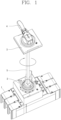
- FIG. 1 shows a circuit breaker having an external handle apparatus according to the related art.
- a drive assembly 2 is provided at an outside of a circuit breaker 1, and a handle assembly 3 having a handle 4 is separately provided to operate the circuit breaker 1 through a shaft 5.
- Such an external operation handle apparatus is accompanied by inconvenience and instability of operation. Furthermore, since the circuit breaker uses a mechanical connection method, there is a limit of an operation distance to the circuit breaker. In addition, since an operation tool is separately provided, there is a risk of loss and damage. Moreover, it is difficult to recognize the internal information of the circuit breaker.
- the present disclosure has been made to solve the above-described problems, and an aspect of the present disclosure is to provide a semiconductor circuit breaker having an interface module that is separated from the circuit breaker to operate the circuit breaker from an outside.
- a semiconductor circuit breaker may include a circuit breaker body connected to a main circuit; and an interface module independent from the circuit breaker body, wherein the circuit breaker body includes a first receiving part provided on an outer surface of the circuit breaker body; and a circuit breaking part having a power semiconductor device connected to the main circuit to break the main circuit when an overcurrent occurs, and the interface module includes an operation part that controls the circuit breaking part, and the interface module is detachably coupled to the first receiving part.
- the interface module or the first receiving part may be provided with a coupling part including a magnet such that the circuit breaker body and the interface module are coupled by a magnetic force.
- the power semiconductor device may be a MOSFET or an IGBT.
- the circuit breaker body may be provided with a power supply part that supplies a current to the circuit breaking part.
- the interface module may be provided with a module power supply part connected to the power supply part in a wired or wireless manner to receive power.
- the power supply part may include an induced current transmitter having a first coil that generates a magnetic field, wherein the module power supply part includes an induced current receiver having a second coil through which an induced current by the magnetic field flows.
- the circuit breaker body may be provided with a communication part that allows wired or wireless transmission and reception, wherein the interface module is provided with a module communication part connected to the communication part in a wired or wirelessly manner.
- the circuit breaker body may be provided with an access part allowing or restricting an electrical connection to the interface module, and the interface module may be provided with a module access part that requests an electrical connection to the access part.
- the operation part may include an on/off button that operates the circuit breaking part to break or connect a circuit.
- the interface module may include a display part that displays the information of the circuit breaker body.
- An external apparatus in which the circuit breaker body is installed may be provided, wherein the external apparatus is provided with a second receiving part on an outer surface thereof such that the interface module is detachably provided in the second receiving part.
- the external apparatus may be provided with a connection part connected to the circuit breaker body in a wired or wireless manner to mediate an electrical connection between the interface module and the circuit breaker body.
- a semiconductor circuit breaker may include an external apparatus provided with a main circuit; a circuit breaker body connected to the main circuit and installed in the external apparatus; and an interface module independent from the circuit breaker body and external apparatus, wherein the circuit breaker body includes a first receiving part provided on an outer surface of the circuit breaker body; and a circuit breaking part including a power semiconductor device connected to the main circuit to break the main circuit when an overcurrent occurs, the external apparatus includes a second receiving part provided on an outer surface thereof, the interface module includes an operation part that controls the circuit breaking part, and the interface module is detachably coupled to the first receiving part or the second receiving part.
- the interface module or the first receiving part or the second receiving part may be provided with a coupling part including a magnet, and the circuit breaker body and the interface module or the external apparatus and the interface module nay be coupled by a magnetic force.
- the circuit breaker body may be provided with a power supply part that supplies a current to the circuit breaking part, wherein the external apparatus is provided with a second power supply part that supplies power to the circuit breaker body or the interface module, and the interface module is provided with a module power supply part connected to the power supply part or the second power supply part in a wired or wireless manner to receive power.
- the power supply part or the second power supply part may include an induced current transmitter having a first coil or a second coil that generates a magnetic field, wherein the module power supply part includes an induced current receiver having a second coil through which an induced current by the magnetic field flows.
- the circuit breaker body may be provided with an access part allowing or restricting an electrical connection to the interface module, and the interface module may be provided with a module access part that requests an electrical connection to the access part.
- the external apparatus may be provided with a connection part that mediates an electrical connection between the circuit breaker body and the interface module.
- an interface module for operating a circuit breaking part may be provided separately from a circuit breaker body, thereby easily operating the circuit breaker disposed at a long distance.
- the interface module may be attached to the circuit breaker body using a magnetic force coupling method, thereby facilitating coupling and decoupling.
- the interface module may be connected to the circuit breaker body in a wired or wireless communication method, thereby extending an operable distance.
- the circuit breaker body may be provided with an access part for allowing or restricting an access to the interface module, thereby controlling an access for each user.
- the interface module may display the internal information of the circuit breaker body, and allow an electrical access as well as a mechanical connection such as operating the circuit breaking part.
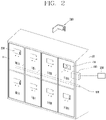
- FIG. 2 is a perspective view of a semiconductor circuit breaker provided in a switchboard according to an embodiment of the present disclosure
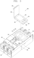
- FIG. 3 is an exploded perspective view of a circuit breaker body and an interface module of a semiconductor circuit breaker according to an embodiment of the present disclosure
- FIG. 4 is a block diagram of a semiconductor circuit breaker according to an embodiment of the present disclosure
- FIG. 5 is a power supply part of a semiconductor circuit breaker according to an embodiment of the present disclosure.
- a semiconductor circuit breaker may include a circuit breaker body 1000 connected to a main circuit 400; and an interface module 200 independent from the circuit breaker body 100, wherein the circuit breaker body 100 includes a first receiving part 110 provided on an outer surface of the circuit breaker body 100; and a circuit breaking part 120 having a power semiconductor device connected to the main circuit 400 to break the main circuit 400 when an overcurrent occurs, and the interface module 200 includes an operation part 220 that controls the circuit breaking part 120, and the interface module 200 is detachably coupled to the first receiving part 110.
- the circuit breaker body 100 is connected to the main circuit 400 and a load 300.
- the circuit breaker body 100 is open when an overcurrent occurs between the main circuit 400 and the load 300 or a fault current such as a ground fault occurs to break the main circuit 400 to protect the load 300 and apparatuses and facilities associated therewith.
- the circuit breaker body 100 may be independently provided and connected between the main circuit 400 and the load 300. Furthermore, the circuit breaker body 100 is integrally installed in the external apparatus 10 to be used as an accessory apparatus.
- the external apparatus 10 may be a power apparatus, for example, a switchboard or an energy storage system (ESS).
- FIG. 2 illustrates a switchboard including a plurality of panels 11 as an example of the external apparatus 10.
- Each panel 11 may be, for example, a panel divided into a high-voltage device chamber, a low-voltage device chamber, a circuit breaker chamber, a cable chamber, and the like.
- the main circuit 400 is connected to each panel 11 and the load 300 to supply power.
- the main circuit 400 may be partially configured with a busbar such as a bus line and partially configured with a cable branched from the bus line.
- a portion where a plurality of power devices are densely connected and power is intensively connected, such as a switchboard may be provided with a bus line configured with a conductor, and a portion connected to an individual apparatus may be connected with a cable.
- the power element apparatuses in the panel 11 may be connected directly to the main circuit 400 or connected indirectly through other power element apparatuses.
- a circuit breaker is provided to break an overcurrent or a fault current flowing in the circuit in the panel 11.
- a semiconductor circuit breaker may be applied. Since breaking speed is fast and no arc is generated during breaking, the semiconductor circuit breaker is more stable than a mechanical circuit breaker.
- the semiconductor circuit breaker of the present embodiment is divided into (separated into) a circuit breaker body 100 and an interface module 200.
- the interface module 200 is detachably coupled to the circuit breaker body 100. That is, the interface module 200 may be independently configured, and may be coupled to or separated from the circuit breaker body 100.
- the circuit breaker body 100 may perform a breaking function (operation) by itself, and may additionally perform a breaking function by the interface module 200. Meanwhile, the interface module 200 may perform an additional function other than the breaking function of the circuit breaker body 100.
- the circuit breaker body 100 is provided with the first receiving part 110.
- the first receiving part 110 is provided on an outer surface of the circuit breaker body 100.
- the first receiving part 110 may be configured with a groove having a predetermined depth as shown in FIG. 3 .
- the present disclosure is not limited thereto, and the first receiving part 110 may be configured with a flat plate or a protrusion portion.
- the first receiving part 110 may be configured with a plurality of position fixing grooves 111 may be provided along a circumferential portion to allow the interface module 200 to be easily and stably inserted and installed therein.
- the interface module 200 may be defined in the form of a plate or box having a predetermined thickness.
- a plurality of insertion protrusions 201 may be formed in the interface module 200 to facilitate insertion into the position fixing groove 111 along the circumference and not to be shaken after installation.
- a cover part 203 may be provided in the interface module 200.
- the cover part 203 may protect the interface module 200, prevent an arbitrary access, and allow a hand to be gripped when attaching to and detaching from the circuit breaker body 100.
- a handle 205 is provided on the cover part 203.
- the cover part 203 may be opened and closed by the handle 205 in an opening/closing manner.
- a coupling part 210 is provided on a rear surface of the interface module 200.
- the coupling part 210 provides a coupling force such that the interface module 200 is attached to the circuit breaker body 100 so as not to be naturally separated. Since the interface module 200 is provided with a force of the coupling part 210, it does not fall freely even when coupled in a standing state, and is not separated from the circuit breaker body 100 within a predetermined force range.
- a mechanical coupling method such as a fitting coupling structure may be applied.
- an attachment coupling method such as Velcro or a hook-and-loop fastener may be applied.
- FIG. 3 illustrates a coupling method by a magnetic force as another example of a coupling method between the interface module 200 and the circuit breaker body 100.
- a magnet (not shown) may be provided in the coupling part 210 of the interface module 200.
- the coupling receiving part 113 is provided in a first receiving part 110 of the circuit breaker body 100.
- the coupling receiving part 113 may be made of a magnetic material to be coupled by a magnetic force of the coupling part 210.
- the coupling receiving part 113 may be made of a metal material.
- the coupling part 210 and the coupling receiving part 113 may be configured in opposite directions.
- both the coupling part 210 and the coupling receiving part 113 may be configured to include a magnet.
- circuit breaker body 100 The configuration of the circuit breaker body 100 will be described in more detail.
- the circuit breaker body 100 is provided with terminal parts 12, 13 configured with a power-side terminal part 103 connected to an external power source 99 and a load-side terminal part 102 connected to the load 300.
- a terminal is provided in each of the terminal parts 102, 103. That is, the load-side terminal part 102 is provided to expose a load-side terminal, and the power-side terminal part 103 is provided to expose a power-side terminal.
- the circuit breaker body 100 is provided with a handle 105 for manually performing a breaking operation by a user's operation. A user may manually operate the circuit breaker body 100.
- a reset button 106 for re-insertion after the circuit breaker trips due to a fault current is provided on one side of the handle 105.
- the reset button 106 provides a reset operation for re-insertion after a trip operation.
- the circuit breaker body 100 is provided with a trip display part 108 for displaying a trip state.
- the circuit breaker body 100 may be provided with a configuration for performing a breaking operation and a re-insertion operation as described above at an outside thereof, and may be installed and used independently. That is, even when the interface module 200 is not connected thereto, a function may be independently performed. Such a function may be selectively provided.
- a mechanical operation configuration may be eliminated, and configured to allow only an operation by the interface module 200. In this case, the manufacturing cost of the circuit breaker body 100 is reduced.
- FIG. 4 is a block diagram illustrating a connection relationship of the external apparatus 10, the circuit breaker body 100, the interface module 200, and the load 300, and a basic configuration of respective apparatuses.
- a power supply part 130 is provided in the circuit breaker body 100.
- the power supply part 130 supplies power to each component in the circuit breaker body 100 such as the circuit breaking part 120.
- the power supply part 130 may be connected to the external power source 99 or may receive independent power by itself.
- the power supply part 130 may include an AC/DC converter or a DC/DC converter.
- the circuit breaker body 100 is provided with a circuit breaking part 120.
- the circuit breaking part 120 is a main contact part that breaks or connects an electrical connection of the main circuit 400.
- the circuit breaking part 120 is provided with a power semiconductor device (not shown) as a core device of the semiconductor circuit breaker.
- a power semiconductor device such as a power semiconductor device, a metal oxide semiconductor field-effect transistor (MOSFET) or an insulated gate bipolar transistor (IGBT) may be applied.
- MOSFET metal oxide semiconductor field-effect transistor
- IGBT insulated gate bipolar transistor
- the circuit breaking part 120 may include a protection circuit (not shown) connected in parallel to the power semiconductor device to protect the power semiconductor device from a sudden voltage generated during switching.
- a protection circuit such as a protection circuit, a snubber circuit or a metal oxide varistor (MOV) may be applied.
- MOV metal oxide varistor
- the power supply part 130 is connected to the external power source 99 to supply power to the circuit breaker body 100. Furthermore, the power supply part 130 may supply power to the interface module 200.
- the interface module 200 is provided with a module power supply part 230.
- the power supply part 130 may be connected to the module power part 230 of the interface module 200 in a wired or wireless manner to supply power.
- FIG. 5 illustrates an example of supplying power from the power supply part 130 to the module power supply part 230 in a wireless charging method.
- the power supply part 130 of the circuit breaker body 100 is provided with an induced current transmitter 135.
- the induced current transmitter 135 is provided with a first coil 137 that generates a magnetic field.
- the module power supply part 230 of the interface module 200 is provided with an induced current receiver 235 including a second coil 237 through which an induced current due to a magnetic field generated by the first coil 137 flows.
- the interface module 200 when the interface module 200 is coupled to the circuit breaker body 100, power may be supplied to an inside of the interface module 200 by a wireless charging method without any separate line connection.
- a battery may be provided in the induced current receiver 235 of the interface module 200 to store electricity generated by the induced current.
- the circuit breaker body 100 is provided with a communication part 140 to allow wired or wireless transmission and reception.
- the interface module 200 is provided with a module communication part 240 connected to the communication part 140 of the circuit breaker body 100 in a wired or wireless manner.
- a short-range wireless communication technology such as Wi-Fi, Bluetooth, or Zigbee may be applied.
- the communication part 140 and the module communication part 240 may be connected to a network by accessing a communication network such as Ethernet.
- the communication part 140 and the module communication part 240 may communicate with each other to transmit an access allowance and restriction, a breaking function for the circuit breaker body 100, internal information of the circuit breaker body 100, and the like.
- the circuit breaker body 100 is provided with a controller 150.
- the controller 150 may be configured with a printed circuit board (PCB) for electrical control.
- PCB printed circuit board
- the controller 150 may be connected to a mechanical operation element such as a reset button 106 or a trip display part 108 provided on an outside of the circuit breaker body 100.
- the controller 150 may be connected to the circuit breaking part 120 to control breaking and connection.
- the controller 150 may provide information of the circuit breaker body 100 to the interface module 200 through the communication part 140 and the module communication part 240.
- the circuit breaker body 100 is provided with an access part 160 to allow or restrict electrical connection with the interface module 200.
- the interface module 200 is provided with a module access part 260 that requests a connection to the access part 160.
- the module access part 260 may communicate with the access part 160 through the communication part 140 and the module communication part 240. Such communication may be controlled by the controller 150 and the module controller 250, respectively.
- the access part 160 may allow, block, or restrict an access to the circuit breaker body 100 through information requested or provided by the module access part 260.
- the access part 160 may confirm an ID of the interface module 200 provided by the module access part 260 and allow, block, or restrict an access to the circuit breaker body 100 based thereon.
- the module access part 260 may contain authority information of the interface module 200. Alternatively, the module access part 260 may receive or provide different authorization information for each user accessing the interface module 200.
- the module access part 260 may include a recognition part for distinguishing and recognizing a user accessing the interface module 200.
- the recognition part may be configured with a sensor such as a fingerprint sensor or an iris sensor.
- respective authority information may be set differently for each user.
- the operation part 220 of the interface module 200 may perform a function of operating the circuit breaker body 100.
- the operation part 220 of the interface module 200 includes an on/off button that operates the circuit breaking part 120 to break or connect the main circuit 400.
- the operation part 220 of the interface module 200 may perform an input/output function.
- the operation part 220 of the interface module 200 may perform a function such as information display of the circuit breaker body 100, access authority display and setting, and the operation of the circuit breaking part 120.
- the interface module 200 is provided with a display part 270.
- the state information of the circuit breaker body 100, access authority information, whether a breaking operation is performed, whether the power supply part is charged, and the like are displayed on the display part 270.
- the external apparatus 10 is configured with a second receiving part 20 on an outer surface thereof.
- the interface module 200 may be detachably coupled to the second receiving part 20.
- the second receiving part 20 may also be provided with a coupling receiving part and a power supply part (induced current transmitter) like the first receiving part 110. Accordingly, the interface module 200 may receive power even in a state of being coupled to the external apparatus 10.
- a connection part 30 of the external apparatus 10 is provided with a second power supply part 40
- the second power supply part 40 is provided with a third coil (not shown).
- the second power supply part 40 may supply power to the interface module 200 or the circuit breaker body 100.
- the external apparatus 10 is provided with the connection part 30 connected to the circuit breaker body 100 in a wired or wireless manner to mediate an electrical connection between the interface module 200 and the circuit breaker body 100.
- a connection function may be selectively set.
- the interface module 200 may be connected only mechanically to the external apparatus 10, and may be directly connected electrically to the circuit breaker body 100 in a wireless manner.
- an interface module for operating a circuit breaking part may be provided separately and independently from a circuit breaker body, thereby easily operating the circuit breaker separated apart therefrom.
- the interface module may be attached to the circuit breaker body using a coupling method by a magnetic force, thereby facilitating coupling and decoupling.
- the interface module may be connected to the circuit breaker body in a wired or wireless communication method, thereby extending an operable distance.
- the circuit breaker body may be provided with an access part for allowing or restricting an access to the interface module, thereby controlling an access for each user.
- the interface module may display the internal information of the circuit breaker body, and allow an electrical access as well as a mechanical connection such as operating the circuit breaking part.
Landscapes
- Engineering & Computer Science (AREA)
- Power Engineering (AREA)
- Computer Networks & Wireless Communication (AREA)
- Breakers (AREA)
Abstract
Description
- The present disclosure relates to a semiconductor circuit breaker, and more particularly, to a semiconductor circuit breaker having a detachable interface module.
- In general, a semiconductor circuit breaker is a circuit breaker designed to break a circuit using a power semiconductor device such as a MOSFET, an IGBT, or the like. Since the semiconductor circuit breaker performs circuit breaking using the current breaking characteristic of the power semiconductor device, an arc is not generated during circuit breaking, so an arc removal function is not required. Therefore, there is an advantage that an arc extinguishing part is removed to reduce its volume. Furthermore, there is an advantage that an arc breaking time is short. On the contrary, a low-capacity circuit breaker has a disadvantage in that manufacturing cost increases due to the use of a power semiconductor device.
- The semiconductor circuit breaker is often used in a system that require quick breaking. In the case of a general mechanical circuit breaker, a breaking speed thereof is several to several hundred ms, whereas a breaking speed of the semiconductor circuit breaker is several tens of µs, thereby breaking a current in a much shorter time.
- Accordingly, the semiconductor circuit breaker is being actively used in a switchboard with a large current capacity, a direct current system with a rapid increase in fault current, or an energy storage system (ESS) that requires stable current supply and breaking. In recent years, considering that ignition occurs in the ESS system, the importance of a circuit breaker for stable current supply considering heat generation is becoming more urgent.
- Although such a circuit breaker is sometimes used individually, it is usually installed and used in a power facility such as a switchboard or a system. In this case, it may be difficult for a user to access and operate the circuit breaker. For example, in the case of a switchboard, it is necessary to open a switchboard door to access and operate the circuit breaker from an outside of the switchboard, and it is difficult to access the circuit breaker in a case where a distance thereto within the switchboard is long.
- In the related art, in order to access the circuit breaker at a long distance, a remote operation tool such as an external operation handle has been used.
-
FIG. 1 shows a circuit breaker having an external handle apparatus according to the related art. Adrive assembly 2 is provided at an outside of acircuit breaker 1, and ahandle assembly 3 having a handle 4 is separately provided to operate thecircuit breaker 1 through ashaft 5. - Such an external operation handle apparatus is accompanied by inconvenience and instability of operation. Furthermore, since the circuit breaker uses a mechanical connection method, there is a limit of an operation distance to the circuit breaker. In addition, since an operation tool is separately provided, there is a risk of loss and damage. Moreover, it is difficult to recognize the internal information of the circuit breaker.
- The present disclosure has been made to solve the above-described problems, and an aspect of the present disclosure is to provide a semiconductor circuit breaker having an interface module that is separated from the circuit breaker to operate the circuit breaker from an outside.
- A semiconductor circuit breaker according to an embodiment of the present disclosure may include a circuit breaker body connected to a main circuit; and an interface module independent from the circuit breaker body, wherein the circuit breaker body includes a first receiving part provided on an outer surface of the circuit breaker body; and a circuit breaking part having a power semiconductor device connected to the main circuit to break the main circuit when an overcurrent occurs, and the interface module includes an operation part that controls the circuit breaking part, and the interface module is detachably coupled to the first receiving part.
- The interface module or the first receiving part may be provided with a coupling part including a magnet such that the circuit breaker body and the interface module are coupled by a magnetic force.
- The power semiconductor device may be a MOSFET or an IGBT.
- The circuit breaker body may be provided with a power supply part that supplies a current to the circuit breaking part.
- The interface module may be provided with a module power supply part connected to the power supply part in a wired or wireless manner to receive power.
- The power supply part may include an induced current transmitter having a first coil that generates a magnetic field, wherein the module power supply part includes an induced current receiver having a second coil through which an induced current by the magnetic field flows.
- The circuit breaker body may be provided with a communication part that allows wired or wireless transmission and reception, wherein the interface module is provided with a module communication part connected to the communication part in a wired or wirelessly manner.
- The circuit breaker body may be provided with an access part allowing or restricting an electrical connection to the interface module, and the interface module may be provided with a module access part that requests an electrical connection to the access part.
- The operation part may include an on/off button that operates the circuit breaking part to break or connect a circuit.
- The interface module may include a display part that displays the information of the circuit breaker body.
- An external apparatus in which the circuit breaker body is installed may be provided, wherein the external apparatus is provided with a second receiving part on an outer surface thereof such that the interface module is detachably provided in the second receiving part.
- The external apparatus may be provided with a connection part connected to the circuit breaker body in a wired or wireless manner to mediate an electrical connection between the interface module and the circuit breaker body.
- A semiconductor circuit breaker according to another aspect of the present disclosure may include an external apparatus provided with a main circuit; a circuit breaker body connected to the main circuit and installed in the external apparatus; and an interface module independent from the circuit breaker body and external apparatus, wherein the circuit breaker body includes a first receiving part provided on an outer surface of the circuit breaker body; and a circuit breaking part including a power semiconductor device connected to the main circuit to break the main circuit when an overcurrent occurs, the external apparatus includes a second receiving part provided on an outer surface thereof, the interface module includes an operation part that controls the circuit breaking part, and the interface module is detachably coupled to the first receiving part or the second receiving part.
- The interface module or the first receiving part or the second receiving part may be provided with a coupling part including a magnet, and the circuit breaker body and the interface module or the external apparatus and the interface module nay be coupled by a magnetic force.
- The circuit breaker body may be provided with a power supply part that supplies a current to the circuit breaking part, wherein the external apparatus is provided with a second power supply part that supplies power to the circuit breaker body or the interface module, and the interface module is provided with a module power supply part connected to the power supply part or the second power supply part in a wired or wireless manner to receive power.
- The power supply part or the second power supply part may include an induced current transmitter having a first coil or a second coil that generates a magnetic field, wherein the module power supply part includes an induced current receiver having a second coil through which an induced current by the magnetic field flows.
- The circuit breaker body may be provided with an access part allowing or restricting an electrical connection to the interface module, and the interface module may be provided with a module access part that requests an electrical connection to the access part.
- Furthermore, the external apparatus may be provided with a connection part that mediates an electrical connection between the circuit breaker body and the interface module.
- According to a semiconductor circuit breaker according to an embodiment of the present disclosure, an interface module for operating a circuit breaking part may be provided separately from a circuit breaker body, thereby easily operating the circuit breaker disposed at a long distance.
- The interface module may be attached to the circuit breaker body using a magnetic force coupling method, thereby facilitating coupling and decoupling.
- The interface module may be connected to the circuit breaker body in a wired or wireless communication method, thereby extending an operable distance.
- The circuit breaker body may be provided with an access part for allowing or restricting an access to the interface module, thereby controlling an access for each user.
- The interface module may display the internal information of the circuit breaker body, and allow an electrical access as well as a mechanical connection such as operating the circuit breaking part.
-
-
FIG. 1 is a perspective view of a circuit breaker having an external handle apparatus according to the related art. -
FIG. 2 is a perspective view of a semiconductor circuit breaker provided in a switchboard according to an embodiment of the present disclosure. -
FIG. 3 is an exploded perspective view of a circuit breaker body and an interface module of a semiconductor circuit breaker according to an embodiment of the present disclosure. -
FIG. 4 is a block diagram of a semiconductor circuit breaker according to an embodiment of the present disclosure. -
FIG. 5 is a power supply part of a semiconductor circuit breaker according to an embodiment of the present disclosure. - Hereinafter, preferred embodiments of the present disclosure will be described with reference to the accompanying drawings, which are intended to describe the present disclosure in detail to allow a person skilled in the art to easily carry out the invention, but not to mean that the technical concept and scope of the present disclosure are limited thereto.
-
FIG. 2 is a perspective view of a semiconductor circuit breaker provided in a switchboard according to an embodiment of the present disclosure,FIG. 3 is an exploded perspective view of a circuit breaker body and an interface module of a semiconductor circuit breaker according to an embodiment of the present disclosure,FIG. 4 is a block diagram of a semiconductor circuit breaker according to an embodiment of the present disclosure, andFIG. 5 is a power supply part of a semiconductor circuit breaker according to an embodiment of the present disclosure. A semiconductor circuit breaker according to each embodiment of the present disclosure will be described in detail with reference to the drawings. - A semiconductor circuit breaker according to an embodiment of the present disclosure may include a circuit breaker body 1000 connected to a
main circuit 400; and aninterface module 200 independent from thecircuit breaker body 100, wherein thecircuit breaker body 100 includes a first receivingpart 110 provided on an outer surface of thecircuit breaker body 100; and acircuit breaking part 120 having a power semiconductor device connected to themain circuit 400 to break themain circuit 400 when an overcurrent occurs, and theinterface module 200 includes anoperation part 220 that controls thecircuit breaking part 120, and theinterface module 200 is detachably coupled to the first receivingpart 110. - The
circuit breaker body 100 is connected to themain circuit 400 and aload 300. Thecircuit breaker body 100 is open when an overcurrent occurs between themain circuit 400 and theload 300 or a fault current such as a ground fault occurs to break themain circuit 400 to protect theload 300 and apparatuses and facilities associated therewith. - The
circuit breaker body 100 may be independently provided and connected between themain circuit 400 and theload 300. Furthermore, thecircuit breaker body 100 is integrally installed in theexternal apparatus 10 to be used as an accessory apparatus. - The
external apparatus 10 may be a power apparatus, for example, a switchboard or an energy storage system (ESS).FIG. 2 illustrates a switchboard including a plurality ofpanels 11 as an example of theexternal apparatus 10. Eachpanel 11 may be, for example, a panel divided into a high-voltage device chamber, a low-voltage device chamber, a circuit breaker chamber, a cable chamber, and the like. - Various electric power device apparatuses are installed in the
panel 11. - The
main circuit 400 is connected to eachpanel 11 and theload 300 to supply power. Themain circuit 400 may be partially configured with a busbar such as a bus line and partially configured with a cable branched from the bus line. For example, a portion where a plurality of power devices are densely connected and power is intensively connected, such as a switchboard may be provided with a bus line configured with a conductor, and a portion connected to an individual apparatus may be connected with a cable. - The power element apparatuses in the
panel 11 may be connected directly to themain circuit 400 or connected indirectly through other power element apparatuses. - A circuit breaker is provided to break an overcurrent or a fault current flowing in the circuit in the
panel 11. For the circuit breaker applied herein, in particular, a semiconductor circuit breaker may be applied. Since breaking speed is fast and no arc is generated during breaking, the semiconductor circuit breaker is more stable than a mechanical circuit breaker. - The semiconductor circuit breaker of the present embodiment is divided into (separated into) a
circuit breaker body 100 and aninterface module 200. - The
interface module 200 is detachably coupled to thecircuit breaker body 100. That is, theinterface module 200 may be independently configured, and may be coupled to or separated from thecircuit breaker body 100. Here, thecircuit breaker body 100 may perform a breaking function (operation) by itself, and may additionally perform a breaking function by theinterface module 200. Meanwhile, theinterface module 200 may perform an additional function other than the breaking function of thecircuit breaker body 100. - The
circuit breaker body 100 is provided with the first receivingpart 110. Thefirst receiving part 110 is provided on an outer surface of thecircuit breaker body 100. Thefirst receiving part 110 may be configured with a groove having a predetermined depth as shown inFIG. 3 . However, the present disclosure is not limited thereto, and the first receivingpart 110 may be configured with a flat plate or a protrusion portion. - The
first receiving part 110 may be configured with a plurality ofposition fixing grooves 111 may be provided along a circumferential portion to allow theinterface module 200 to be easily and stably inserted and installed therein. - The
interface module 200 may be defined in the form of a plate or box having a predetermined thickness. - A plurality of
insertion protrusions 201 may be formed in theinterface module 200 to facilitate insertion into theposition fixing groove 111 along the circumference and not to be shaken after installation. - A
cover part 203 may be provided in theinterface module 200. Thecover part 203 may protect theinterface module 200, prevent an arbitrary access, and allow a hand to be gripped when attaching to and detaching from thecircuit breaker body 100. - A
handle 205 is provided on thecover part 203. Thecover part 203 may be opened and closed by thehandle 205 in an opening/closing manner. - A
coupling part 210 is provided on a rear surface of theinterface module 200. Thecoupling part 210 provides a coupling force such that theinterface module 200 is attached to thecircuit breaker body 100 so as not to be naturally separated. Since theinterface module 200 is provided with a force of thecoupling part 210, it does not fall freely even when coupled in a standing state, and is not separated from thecircuit breaker body 100 within a predetermined force range. - For an example of a coupling method between the
interface module 200 and thecircuit breaker body 100, a mechanical coupling method such as a fitting coupling structure may be applied. Furthermore, an attachment coupling method such as Velcro or a hook-and-loop fastener may be applied. -
FIG. 3 illustrates a coupling method by a magnetic force as another example of a coupling method between theinterface module 200 and thecircuit breaker body 100. A magnet (not shown) may be provided in thecoupling part 210 of theinterface module 200. Meanwhile, thecoupling receiving part 113 is provided in a first receivingpart 110 of thecircuit breaker body 100. Thecoupling receiving part 113 may be made of a magnetic material to be coupled by a magnetic force of thecoupling part 210. For example, thecoupling receiving part 113 may be made of a metal material. - Furthermore, the
coupling part 210 and thecoupling receiving part 113 may be configured in opposite directions. In addition, both thecoupling part 210 and thecoupling receiving part 113 may be configured to include a magnet. - The configuration of the
circuit breaker body 100 will be described in more detail. - The
circuit breaker body 100 is provided with terminal parts 12, 13 configured with a power-side terminal part 103 connected to anexternal power source 99 and a load-side terminal part 102 connected to theload 300. A terminal is provided in each of theterminal parts side terminal part 102 is provided to expose a load-side terminal, and the power-side terminal part 103 is provided to expose a power-side terminal. - The
circuit breaker body 100 is provided with ahandle 105 for manually performing a breaking operation by a user's operation. A user may manually operate thecircuit breaker body 100. - A
reset button 106 for re-insertion after the circuit breaker trips due to a fault current is provided on one side of thehandle 105. Thereset button 106 provides a reset operation for re-insertion after a trip operation. - The
circuit breaker body 100 is provided with atrip display part 108 for displaying a trip state. - The
circuit breaker body 100 may be provided with a configuration for performing a breaking operation and a re-insertion operation as described above at an outside thereof, and may be installed and used independently. That is, even when theinterface module 200 is not connected thereto, a function may be independently performed. Such a function may be selectively provided. When thecircuit breaker body 100 is applied only as a passive terminal operator, such a mechanical operation configuration may be eliminated, and configured to allow only an operation by theinterface module 200. In this case, the manufacturing cost of thecircuit breaker body 100 is reduced. -
FIG. 4 is a block diagram illustrating a connection relationship of theexternal apparatus 10, thecircuit breaker body 100, theinterface module 200, and theload 300, and a basic configuration of respective apparatuses. - First, the
circuit breaker body 100 will be described. - A
power supply part 130 is provided in thecircuit breaker body 100. Thepower supply part 130 supplies power to each component in thecircuit breaker body 100 such as thecircuit breaking part 120. - The
power supply part 130 may be connected to theexternal power source 99 or may receive independent power by itself. Thepower supply part 130 may include an AC/DC converter or a DC/DC converter. - The
circuit breaker body 100 is provided with acircuit breaking part 120. - The
circuit breaking part 120 is a main contact part that breaks or connects an electrical connection of themain circuit 400. Thecircuit breaking part 120 is provided with a power semiconductor device (not shown) as a core device of the semiconductor circuit breaker. As such a power semiconductor device, a metal oxide semiconductor field-effect transistor (MOSFET) or an insulated gate bipolar transistor (IGBT) may be applied. - The
circuit breaking part 120 may include a protection circuit (not shown) connected in parallel to the power semiconductor device to protect the power semiconductor device from a sudden voltage generated during switching. As an example of such a protection circuit, a snubber circuit or a metal oxide varistor (MOV) may be applied. For the detailed configuration or operation of the circuit breaking part and the protection circuit, reference may be made to the applicant's application "bidirectional semiconductor circuit breaker (10-2019-0042659)" and the like. - The
power supply part 130 is connected to theexternal power source 99 to supply power to thecircuit breaker body 100. Furthermore, thepower supply part 130 may supply power to theinterface module 200. Theinterface module 200 is provided with a modulepower supply part 230. - The
power supply part 130 may be connected to themodule power part 230 of theinterface module 200 in a wired or wireless manner to supply power. -
FIG. 5 illustrates an example of supplying power from thepower supply part 130 to the modulepower supply part 230 in a wireless charging method. - The
power supply part 130 of thecircuit breaker body 100 is provided with an inducedcurrent transmitter 135. The inducedcurrent transmitter 135 is provided with afirst coil 137 that generates a magnetic field. - The module
power supply part 230 of theinterface module 200 is provided with an inducedcurrent receiver 235 including asecond coil 237 through which an induced current due to a magnetic field generated by thefirst coil 137 flows. - Accordingly, when the
interface module 200 is coupled to thecircuit breaker body 100, power may be supplied to an inside of theinterface module 200 by a wireless charging method without any separate line connection. - A battery may be provided in the induced
current receiver 235 of theinterface module 200 to store electricity generated by the induced current. - The
circuit breaker body 100 is provided with acommunication part 140 to allow wired or wireless transmission and reception. - The
interface module 200 is provided with amodule communication part 240 connected to thecommunication part 140 of thecircuit breaker body 100 in a wired or wireless manner. Here, for the wireless communication method, a short-range wireless communication technology such as Wi-Fi, Bluetooth, or Zigbee may be applied. - Meanwhile, the
communication part 140 and themodule communication part 240 may be connected to a network by accessing a communication network such as Ethernet. - The
communication part 140 and themodule communication part 240 may communicate with each other to transmit an access allowance and restriction, a breaking function for thecircuit breaker body 100, internal information of thecircuit breaker body 100, and the like. - The
circuit breaker body 100 is provided with acontroller 150. Thecontroller 150 may be configured with a printed circuit board (PCB) for electrical control. - The
controller 150 may be connected to a mechanical operation element such as areset button 106 or atrip display part 108 provided on an outside of thecircuit breaker body 100. - The
controller 150 may be connected to thecircuit breaking part 120 to control breaking and connection. - The
controller 150 may provide information of thecircuit breaker body 100 to theinterface module 200 through thecommunication part 140 and themodule communication part 240. - The
circuit breaker body 100 is provided with anaccess part 160 to allow or restrict electrical connection with theinterface module 200. - The
interface module 200 is provided with amodule access part 260 that requests a connection to theaccess part 160. - The
module access part 260 may communicate with theaccess part 160 through thecommunication part 140 and themodule communication part 240. Such communication may be controlled by thecontroller 150 and themodule controller 250, respectively. - The
access part 160 may allow, block, or restrict an access to thecircuit breaker body 100 through information requested or provided by themodule access part 260. - The
access part 160 may confirm an ID of theinterface module 200 provided by themodule access part 260 and allow, block, or restrict an access to thecircuit breaker body 100 based thereon. - The
module access part 260 may contain authority information of theinterface module 200. Alternatively, themodule access part 260 may receive or provide different authorization information for each user accessing theinterface module 200. - The
module access part 260 may include a recognition part for distinguishing and recognizing a user accessing theinterface module 200. The recognition part may be configured with a sensor such as a fingerprint sensor or an iris sensor. - In the
module access part 260, respective authority information may be set differently for each user. - The
operation part 220 of theinterface module 200 may perform a function of operating thecircuit breaker body 100. Theoperation part 220 of theinterface module 200 includes an on/off button that operates thecircuit breaking part 120 to break or connect themain circuit 400. Theoperation part 220 of theinterface module 200 may perform an input/output function. Theoperation part 220 of theinterface module 200 may perform a function such as information display of thecircuit breaker body 100, access authority display and setting, and the operation of thecircuit breaking part 120. - The
interface module 200 is provided with adisplay part 270. The state information of thecircuit breaker body 100, access authority information, whether a breaking operation is performed, whether the power supply part is charged, and the like are displayed on thedisplay part 270. - Referring to
FIGS. 2 and4 , theexternal apparatus 10 is configured with a second receivingpart 20 on an outer surface thereof. Theinterface module 200 may be detachably coupled to the second receivingpart 20. Although not separately indicated by reference numerals, the second receivingpart 20 may also be provided with a coupling receiving part and a power supply part (induced current transmitter) like the first receivingpart 110. Accordingly, theinterface module 200 may receive power even in a state of being coupled to theexternal apparatus 10. For an example, aconnection part 30 of theexternal apparatus 10 is provided with a secondpower supply part 40, and the secondpower supply part 40 is provided with a third coil (not shown). - The second
power supply part 40 may supply power to theinterface module 200 or thecircuit breaker body 100. - The
external apparatus 10 is provided with theconnection part 30 connected to thecircuit breaker body 100 in a wired or wireless manner to mediate an electrical connection between theinterface module 200 and thecircuit breaker body 100. Such a connection function may be selectively set. For example, theinterface module 200 may be connected only mechanically to theexternal apparatus 10, and may be directly connected electrically to thecircuit breaker body 100 in a wireless manner. - According to a semiconductor circuit breaker according to an embodiment of the present disclosure, an interface module for operating a circuit breaking part may be provided separately and independently from a circuit breaker body, thereby easily operating the circuit breaker separated apart therefrom.
- The interface module may be attached to the circuit breaker body using a coupling method by a magnetic force, thereby facilitating coupling and decoupling.
- The interface module may be connected to the circuit breaker body in a wired or wireless communication method, thereby extending an operable distance.
- The circuit breaker body may be provided with an access part for allowing or restricting an access to the interface module, thereby controlling an access for each user.
- The interface module may display the internal information of the circuit breaker body, and allow an electrical access as well as a mechanical connection such as operating the circuit breaking part.
- The embodiments described above are embodiments implementing the present disclosure, and it will be apparent to those skilled in this art that various changes and modifications may be made thereto without departing from the gist of the present disclosure. Accordingly, it should be noted that the embodiments disclosed in the present disclosure are only illustrative and not limitative to the concept of the present disclosure, and the scope of the concept of the invention is not limited by those embodiments. In other words, the scope protected by the present disclosure should be construed by the accompanying claims, and all the technical concept within the equivalent scope of the invention should be construed to be included in the scope of the right of the present disclosure.
Claims (17)
- A semiconductor circuit breaker comprising:a circuit breaker body connected to a main circuit; andan interface module independent from the circuit breaker body,wherein the circuit breaker body comprises:a first receiving part provided on an outer surface of the circuit breaker body; anda circuit breaking part having a power semiconductor device connected to the main circuit to break the main circuit when an overcurrent occurs, andwherein the interface module comprises an operation part that controls the circuit breaking part, and the interface module is detachably coupled to the first receiving part.
- The semiconductor circuit breaker of claim 1, wherein the interface module or the first receiving part is provided with a coupling part comprising a magnet such that the circuit breaker body and the interface module are coupled by a magnetic force.
- The semiconductor circuit breaker of claim 1, wherein the power semiconductor device is a MOSFET or an IGBT.
- The semiconductor circuit breaker of claim 1, wherein the circuit breaker body is provided with a power supply part that supplies a current to the circuit breaking part, and
wherein the interface module is provided with a module power supply part connected to the power supply part in a wired or wireless manner to receive power. - The semiconductor circuit breaker of claim 4, wherein the power supply part comprises an induced current transmitter having a first coil that generates a magnetic field, and
wherein the module power supply part comprises an induced current receiver having a second coil through which an induced current by the magnetic field flows. - The semiconductor circuit breaker of claim 1, wherein the circuit breaker body is provided with a communication part that allows wired or wireless transmission and reception, and
wherein the interface module is provided with a module communication part connected to the communication part in a wired or wirelessly manner. - The semiconductor circuit breaker of claim 1, wherein the circuit breaker body is provided with an access part allowing or restricting an electrical connection to the interface module, and
wherein the interface module is provided with a module access part that requests an electrical connection to the access part. - The semiconductor circuit breaker of claim 1, wherein the operation part comprises an on/off button that operates the circuit breaking part to break or connect a circuit.
- The semiconductor circuit breaker of claim 1, wherein the interface module comprises a display part that displays the information of the circuit breaker body.
- The semiconductor circuit breaker of claim 1, wherein an external apparatus in which the circuit breaker body is installed is provided, and
wherein the external apparatus is provided with a second receiving part on an outer surface thereof such that the interface module is detachably provided in the second receiving part. - The semiconductor circuit breaker of claim 10, wherein the external apparatus is provided with a connection part connected to the circuit breaker body in a wired or wireless manner to mediate an electrical connection between the interface module and the circuit breaker body.
- A semiconductor circuit breaker comprising:an external apparatus provided with a main circuit;a circuit breaker body connected to the main circuit and installed in the external apparatus; andan interface module independent from the circuit breaker body and external apparatus,wherein the circuit breaker body comprises:a first receiving part provided on an outer surface of the circuit breaker body; anda circuit breaking part comprising a power semiconductor device connected to the main circuit to break the main circuit when an overcurrent occurs,wherein the external apparatus comprises a second receiving part provided on an outer surface thereof,wherein the interface module comprises an operation part that controls the circuit breaking part, andwherein the interface module is detachably coupled to the first receiving part or the second receiving part.
- The semiconductor circuit breaker of claim 12, wherein the interface module or the first receiving part or the second receiving part is provided with a coupling part comprising a magnet, and the circuit breaker body and the interface module or the external apparatus and the interface module are coupled by a magnetic force.
- The semiconductor circuit breaker of claim 12, wherein the circuit breaker body is provided with a power supply part that supplies a current to the circuit breaking part,wherein the external apparatus is provided with a second power supply part that supplies power to the circuit breaker body or the interface module, andwherein the interface module is provided with a module power supply part connected to the power supply part or the second power supply part in a wired or wireless manner to receive power.
- The semiconductor circuit breaker of claim 14, wherein the power supply part or the second power supply part comprises an induced current transmitter having a first coil or a second coil that generates a magnetic field, and
wherein the module power supply part comprises an induced current receiver having a second coil through which an induced current by the magnetic field flows. - The semiconductor circuit breaker of claim 12, wherein the circuit breaker body is provided with an access part allowing or restricting an electrical connection to the interface module, and
wherein the interface module is provided with a module access part that requests an electrical connection to the access part. - The semiconductor circuit breaker of claim 12, wherein the external apparatus is provided with a connection part that mediates an electrical connection between the circuit breaker body and the interface module.
Applications Claiming Priority (2)
| Application Number | Priority Date | Filing Date | Title |
|---|---|---|---|
| KR1020200053381A KR102485881B1 (en) | 2020-05-04 | 2020-05-04 | Solid State Circuit Breaker |
| PCT/KR2021/003830 WO2021225280A1 (en) | 2020-05-04 | 2021-03-29 | Semiconductor circuit breaker |
Publications (2)
| Publication Number | Publication Date |
|---|---|
| EP4148757A1 true EP4148757A1 (en) | 2023-03-15 |
| EP4148757A4 EP4148757A4 (en) | 2024-05-22 |
Family
ID=78468219
Family Applications (1)
| Application Number | Title | Priority Date | Filing Date |
|---|---|---|---|
| EP21799536.4A Pending EP4148757A4 (en) | 2020-05-04 | 2021-03-29 | Semiconductor circuit breaker |
Country Status (5)
| Country | Link |
|---|---|
| US (1) | US12340965B2 (en) |
| EP (1) | EP4148757A4 (en) |
| KR (1) | KR102485881B1 (en) |
| CN (1) | CN115516591A (en) |
| WO (1) | WO2021225280A1 (en) |
Families Citing this family (1)
| Publication number | Priority date | Publication date | Assignee | Title |
|---|---|---|---|---|
| KR102485881B1 (en) | 2020-05-04 | 2023-01-06 | 엘에스일렉트릭(주) | Solid State Circuit Breaker |
Family Cites Families (31)
| Publication number | Priority date | Publication date | Assignee | Title |
|---|---|---|---|---|
| US4814712A (en) * | 1987-06-17 | 1989-03-21 | General Electric Company | Test kit for a circuit breaker containing an electronic trip unit |
| US4870531A (en) * | 1988-08-15 | 1989-09-26 | General Electric Company | Circuit breaker with removable display and keypad |
| US4991042A (en) * | 1990-03-19 | 1991-02-05 | General Electric Company | Digital circuit interrupter with keypad data entry and display |
| US5303113A (en) * | 1992-03-30 | 1994-04-12 | General Electric Company | Digital circuit interrupter with RFI and EMI shielding |
| FR2756095B1 (en) * | 1996-11-15 | 1998-12-24 | Schneider Electric Sa | CIRCUIT BREAKER WITH A CIRCUIT BREAKER AND PROCESSING, CALIBRATION AND COMMUNICATION MODULES |
| CA2251506A1 (en) * | 1997-10-27 | 1999-04-27 | Lloyd A. Maloney | Assembly for electrically connecting a circuit breaker and a trip unit |
| JP2001218313A (en) * | 2000-01-31 | 2001-08-10 | Toshiba Lighting & Technology Corp | Overcurrent alarm device and distribution board |
| US6724284B2 (en) * | 2001-02-02 | 2004-04-20 | Eaton Corporation | Circuit breaker |
| US6678135B2 (en) * | 2001-09-12 | 2004-01-13 | General Electric Company | Module plug for an electronic trip unit |
| WO2003058788A1 (en) * | 2001-12-21 | 2003-07-17 | Caltek Corporation | Miniaturized motor overload protector |
| US6861931B1 (en) * | 2004-03-01 | 2005-03-01 | Joseph J. Corliss | Portable remote control circuit breaker system |
| KR101084790B1 (en) * | 2006-03-22 | 2011-11-21 | 주식회사 에너솔라 | Semiconductor distribution board supporting ubiquitous environment |
| US7725295B2 (en) * | 2006-11-01 | 2010-05-25 | Abb Research Ltd. | Cable fault detection |
| US8341837B2 (en) * | 2007-05-25 | 2013-01-01 | Braunstein Zachary L | Modular power distribution and control system |
| US8144445B2 (en) * | 2007-06-12 | 2012-03-27 | General Electric Company | Micro-electromechanical system based switching |
| US7859811B2 (en) * | 2007-09-19 | 2010-12-28 | General Electric Company | Modular communication plug-in module for an electronic trip unit |
| EP2068336A1 (en) * | 2007-12-05 | 2009-06-10 | ABB Technology AG | Protective relay and human-machine interface there for |
| US8773827B2 (en) * | 2008-02-19 | 2014-07-08 | Simply Automated Incorporated | Intelligent circuit breaker apparatus and methods |
| KR20090096368A (en) * | 2008-03-07 | 2009-09-10 | (주)한빛테크 | Digital Automatic Trip Apparatus |
| EP2109129B1 (en) * | 2008-04-11 | 2016-03-30 | ABB Technology AG | Medium voltage circuit breaker with integrated electronic protection unit |
| US8120886B2 (en) * | 2008-09-04 | 2012-02-21 | General Electric Company | Circuit breaker closing actuator and method of operation |
| US9025294B2 (en) * | 2012-02-24 | 2015-05-05 | Hamilton Sundstrand Corporation | System and method for controlling solid state circuit breakers |
| US20130271895A1 (en) * | 2012-04-12 | 2013-10-17 | Hampden Kuhns | User installable branch circuit meter |
| US9231410B2 (en) * | 2013-01-04 | 2016-01-05 | Otter Products, Llc | Electronic device case |
| US9432214B2 (en) * | 2013-05-15 | 2016-08-30 | Eaton Corporation | Load panel including an aggregator component and a number of electrical switching apparatus assigning unique addresses thereto |
| JP6366135B2 (en) * | 2014-07-30 | 2018-08-01 | パナソニック株式会社 | Distribution board cabinet, distribution board, and distribution board manufacturing method |
| US10361043B2 (en) * | 2014-12-05 | 2019-07-23 | Eaton Intelligent Power Limited | Circuit breaker including remote operation circuit |
| KR101554903B1 (en) * | 2015-05-28 | 2015-09-22 | (주)이레이티에스 | Earthquake-proof switch board using adapter for combining circuit breaker and switch board |
| US10811865B2 (en) * | 2018-02-23 | 2020-10-20 | Eaton Intelligent Power Limited | Devices, systems, and methods for obtaining operational data from circuit breakers |
| KR102698903B1 (en) * | 2019-04-17 | 2024-08-27 | 엘에스일렉트릭(주) | Circuit Breaker having detachable Electricity Measuring Device |
| KR102485881B1 (en) | 2020-05-04 | 2023-01-06 | 엘에스일렉트릭(주) | Solid State Circuit Breaker |
-
2020
- 2020-05-04 KR KR1020200053381A patent/KR102485881B1/en active Active
-
2021
- 2021-03-29 CN CN202180032624.XA patent/CN115516591A/en active Pending
- 2021-03-29 WO PCT/KR2021/003830 patent/WO2021225280A1/en not_active Ceased
- 2021-03-29 US US17/923,154 patent/US12340965B2/en active Active
- 2021-03-29 EP EP21799536.4A patent/EP4148757A4/en active Pending
Also Published As
| Publication number | Publication date |
|---|---|
| US20230223228A1 (en) | 2023-07-13 |
| EP4148757A4 (en) | 2024-05-22 |
| KR20210135106A (en) | 2021-11-12 |
| KR102485881B1 (en) | 2023-01-06 |
| WO2021225280A1 (en) | 2021-11-11 |
| CN115516591A (en) | 2022-12-23 |
| US12340965B2 (en) | 2025-06-24 |
Similar Documents
| Publication | Publication Date | Title |
|---|---|---|
| CN215498298U (en) | Terminals and Terminal Blocks | |
| EP2830188B1 (en) | Wireless charger equipped with auxiliary power supply and auxiliary power device | |
| EP2418750B1 (en) | Structure of battery disconnection unit for electric vehicle | |
| US6115277A (en) | Battery charger adapter for military vehicles | |
| JP5409737B2 (en) | Power supply system, electric vehicle, and charging adapter | |
| US10931127B2 (en) | Modular charging system and wall-mounted charging device and modular power devices | |
| EP3121056A1 (en) | Battery disconnect unit | |
| KR20120062792A (en) | Inductively chargeable power pack | |
| EP1826841A2 (en) | Charging apparatus | |
| CN109075581A (en) | Battery disconnection circuit and method for controlling battery disconnection circuit | |
| US12340965B2 (en) | Semiconductor circuit breaker | |
| TW201234735A (en) | Electronic device, module and system | |
| WO2015040649A1 (en) | Wireless power transmission device | |
| CN111169300A (en) | Device for charging a battery of an electrically driven motor vehicle | |
| US20230178925A1 (en) | Plug-in contact apparatus for preventing an arc when disconnecting a dc connection | |
| EP2068422A1 (en) | Serial stage power supply combination for emergency auxiliary charging apparatus | |
| US12068125B2 (en) | Semiconductor circuit breaker | |
| KR20220070798A (en) | Electric vehicle charging controller | |
| JP2010200561A (en) | Charging equipment | |
| CN119189724A (en) | A battery charging and distribution integrated box, a vehicle high-current charging device and a vehicle charging method | |
| US20050094338A1 (en) | Recloser control apparatus compatible with various reclosers for protection of power systems | |
| KR20210135105A (en) | Solid State Circuit Breaker | |
| KR101159451B1 (en) | Many voltage combination reverse connection safety device of electric charger. | |
| JP2010154703A (en) | Charging device | |
| WO2021162291A1 (en) | Relay device and electric vehicle charging controller comprising same |
Legal Events
| Date | Code | Title | Description |
|---|---|---|---|
| STAA | Information on the status of an ep patent application or granted ep patent |
Free format text: STATUS: THE INTERNATIONAL PUBLICATION HAS BEEN MADE |
|
| PUAI | Public reference made under article 153(3) epc to a published international application that has entered the european phase |
Free format text: ORIGINAL CODE: 0009012 |
|
| STAA | Information on the status of an ep patent application or granted ep patent |
Free format text: STATUS: REQUEST FOR EXAMINATION WAS MADE |
|
| 17P | Request for examination filed |
Effective date: 20221102 |
|
| AK | Designated contracting states |
Kind code of ref document: A1 Designated state(s): AL AT BE BG CH CY CZ DE DK EE ES FI FR GB GR HR HU IE IS IT LI LT LU LV MC MK MT NL NO PL PT RO RS SE SI SK SM TR |
|
| DAV | Request for validation of the european patent (deleted) | ||
| DAX | Request for extension of the european patent (deleted) | ||
| A4 | Supplementary search report drawn up and despatched |
Effective date: 20240418 |
|
| RIC1 | Information provided on ipc code assigned before grant |
Ipc: H01F 7/02 20060101ALI20240412BHEP Ipc: H01H 71/02 20060101ALI20240412BHEP Ipc: H02J 50/10 20160101ALI20240412BHEP Ipc: H01F 38/14 20060101ALI20240412BHEP Ipc: H02H 3/08 20060101ALI20240412BHEP Ipc: H01H 9/54 20060101AFI20240412BHEP |