EP4148750A1 - Magnetic flux optimization for uniquely shaped designs - Google Patents
Magnetic flux optimization for uniquely shaped designs Download PDFInfo
- Publication number
- EP4148750A1 EP4148750A1 EP22195392.0A EP22195392A EP4148750A1 EP 4148750 A1 EP4148750 A1 EP 4148750A1 EP 22195392 A EP22195392 A EP 22195392A EP 4148750 A1 EP4148750 A1 EP 4148750A1
- Authority
- EP
- European Patent Office
- Prior art keywords
- fluid
- fibers
- fillers
- cavity
- magnetically permeable
- Prior art date
- Legal status (The legal status is an assumption and is not a legal conclusion. Google has not performed a legal analysis and makes no representation as to the accuracy of the status listed.)
- Pending
Links
Images


Classifications
-
- H—ELECTRICITY
- H01—ELECTRIC ELEMENTS
- H01F—MAGNETS; INDUCTANCES; TRANSFORMERS; SELECTION OF MATERIALS FOR THEIR MAGNETIC PROPERTIES
- H01F1/00—Magnets or magnetic bodies characterised by the magnetic materials therefor; Selection of materials for their magnetic properties
- H01F1/44—Magnets or magnetic bodies characterised by the magnetic materials therefor; Selection of materials for their magnetic properties of magnetic liquids, e.g. ferrofluids
- H01F1/442—Magnets or magnetic bodies characterised by the magnetic materials therefor; Selection of materials for their magnetic properties of magnetic liquids, e.g. ferrofluids the magnetic component being a metal or alloy, e.g. Fe
-
- H—ELECTRICITY
- H02—GENERATION; CONVERSION OR DISTRIBUTION OF ELECTRIC POWER
- H02K—DYNAMO-ELECTRIC MACHINES
- H02K15/00—Processes or apparatus specially adapted for manufacturing, assembling, maintaining or repairing of dynamo-electric machines
- H02K15/02—Processes or apparatus specially adapted for manufacturing, assembling, maintaining or repairing of dynamo-electric machines of stator or rotor bodies
- H02K15/03—Processes or apparatus specially adapted for manufacturing, assembling, maintaining or repairing of dynamo-electric machines of stator or rotor bodies having permanent magnets
-
- H—ELECTRICITY
- H01—ELECTRIC ELEMENTS
- H01F—MAGNETS; INDUCTANCES; TRANSFORMERS; SELECTION OF MATERIALS FOR THEIR MAGNETIC PROPERTIES
- H01F1/00—Magnets or magnetic bodies characterised by the magnetic materials therefor; Selection of materials for their magnetic properties
- H01F1/01—Magnets or magnetic bodies characterised by the magnetic materials therefor; Selection of materials for their magnetic properties of inorganic materials
- H01F1/03—Magnets or magnetic bodies characterised by the magnetic materials therefor; Selection of materials for their magnetic properties of inorganic materials characterised by their coercivity
- H01F1/12—Magnets or magnetic bodies characterised by the magnetic materials therefor; Selection of materials for their magnetic properties of inorganic materials characterised by their coercivity of soft-magnetic materials
- H01F1/14—Magnets or magnetic bodies characterised by the magnetic materials therefor; Selection of materials for their magnetic properties of inorganic materials characterised by their coercivity of soft-magnetic materials metals or alloys
- H01F1/20—Magnets or magnetic bodies characterised by the magnetic materials therefor; Selection of materials for their magnetic properties of inorganic materials characterised by their coercivity of soft-magnetic materials metals or alloys in the form of particles, e.g. powder
- H01F1/28—Magnets or magnetic bodies characterised by the magnetic materials therefor; Selection of materials for their magnetic properties of inorganic materials characterised by their coercivity of soft-magnetic materials metals or alloys in the form of particles, e.g. powder dispersed or suspended in a bonding agent
-
- H—ELECTRICITY
- H01—ELECTRIC ELEMENTS
- H01F—MAGNETS; INDUCTANCES; TRANSFORMERS; SELECTION OF MATERIALS FOR THEIR MAGNETIC PROPERTIES
- H01F41/00—Apparatus or processes specially adapted for manufacturing or assembling magnets, inductances or transformers; Apparatus or processes specially adapted for manufacturing materials characterised by their magnetic properties
- H01F41/02—Apparatus or processes specially adapted for manufacturing or assembling magnets, inductances or transformers; Apparatus or processes specially adapted for manufacturing materials characterised by their magnetic properties for manufacturing cores, coils, or magnets
- H01F41/0206—Manufacturing of magnetic cores by mechanical means
- H01F41/0246—Manufacturing of magnetic circuits by moulding or by pressing powder
-
- H—ELECTRICITY
- H02—GENERATION; CONVERSION OR DISTRIBUTION OF ELECTRIC POWER
- H02K—DYNAMO-ELECTRIC MACHINES
- H02K1/00—Details of the magnetic circuit
- H02K1/02—Details of the magnetic circuit characterised by the magnetic material
-
- H—ELECTRICITY
- H02—GENERATION; CONVERSION OR DISTRIBUTION OF ELECTRIC POWER
- H02K—DYNAMO-ELECTRIC MACHINES
- H02K15/00—Processes or apparatus specially adapted for manufacturing, assembling, maintaining or repairing of dynamo-electric machines
- H02K15/12—Impregnating, moulding insulation, heating or drying of windings, stators, rotors or machines
-
- Y—GENERAL TAGGING OF NEW TECHNOLOGICAL DEVELOPMENTS; GENERAL TAGGING OF CROSS-SECTIONAL TECHNOLOGIES SPANNING OVER SEVERAL SECTIONS OF THE IPC; TECHNICAL SUBJECTS COVERED BY FORMER USPC CROSS-REFERENCE ART COLLECTIONS [XRACs] AND DIGESTS
- Y10—TECHNICAL SUBJECTS COVERED BY FORMER USPC
- Y10T—TECHNICAL SUBJECTS COVERED BY FORMER US CLASSIFICATION
- Y10T29/00—Metal working
- Y10T29/49—Method of mechanical manufacture
- Y10T29/49803—Magnetically shaping
Definitions
- the present disclosure relates to optimal flux path creation with magnetorheological (MR) fluids and, more particularly, to optimal flux path creation with MR fluids for forming uniquely shaped features, such as stators for electric motors, so that solid metal alloys are not needed.
- MR magnetorheological
- magnetic materials are often required for completing magnetic circuits.
- these magnetic materials take the form of a solid metal alloy using either a bulk material or laminar sheets to orient and optimize magnetic flux from one location to another location. While these magnetic materials provide benefits in terms of orienting and optimizing magnetic flux, it is often the case that they cannot be easily or reliably formed into complex shapes.
- a method of forming magnetically permeable material includes introducing magnetorheological (MR) fluid including one or more of magnetically permeable particles, fibers and fillers suspended in a curable liquid into a cavity, driving the magnetically permeable particles, fibers and/or fillers in the MR fluid into flux line formations and curing the curable liquid of the MR fluid during the driving to lock the flux line formations in place.
- MR magnetorheological
- the one or more magnetically permeable particles, fibers and fillers include one or more of cobalt powder particles, fibers and/or fillers, iron-cobalt alloy powder particles, fibers and/or fillers and iron powder particles, fibers and/or fillers.
- the curable liquid includes one or more of resin and epoxy.
- the curing includes one or more of heating and irradiating.
- the cavity has a shape of a stator of an electric motor.
- the introducing includes assembling a mold defining the cavity and introducing the MR fluid into the cavity via an opening in the mold.
- the driving of the one or more magnetically permeable particles, fibers and fillers in the MR fluid into the flux line formations includes at least one of activating electromagnetic coils proximate to the MR fluid in the cavity and positioning permanent magnets proximate to the MR fluid in the cavity.
- the method further includes establishing desired arrangements of the flux line formations and arranging at least one of the electromagnetic coils and the permanent magnets proximate to the MR fluid in the cavity in accordance with the desired arrangements of the flux line formations.
- a method of forming magnetically permeable material includes suspending one or more magnetically permeable particles, fibers and fillers in a curable liquid to produce a magnetorheological (MR) fluid, introducing the MR fluid into a cavity, applying a magnetic field to the MR fluid in the cavity to drive the one or more magnetically permeable particles, fibers and fillers in the MR fluid into flux line formations and curing the curable liquid of the MR fluid while the applying of the magnetic field to the MR fluid in the cavity continues to lock the flux line formations in place.
- MR magnetorheological
- the one or more magnetically permeable particles, fibers and fillers include one or more of cobalt powder particles, fibers and/or fillers, iron-cobalt alloy powder particles, fibers and/or fillers and iron powder particles, fibers and/or fillers.
- the curable liquid includes one or more of resin and epoxy.
- the curing includes one or more of heating and irradiating.
- the cavity has a shape of a stator of an electric motor.
- the introducing includes assembling a mold defining the cavity and introducing the MR fluid into the cavity via an opening in the mold.
- the applying of the magnetic field to the MR fluid in the cavity includes at least one of activating electromagnetic coils proximate to the MR fluid in the cavity and positioning permanent magnets proximate to the MR fluid in the cavity.
- the method further includes establishing desired arrangements of the flux line formations and arranging at least one of the electromagnetic coils and the permanent magnets proximate to the MR fluid in the cavity in accordance with the desired arrangements of the flux line formations.
- a magnetically permeable material component includes a cured liquid and one or more magnetically permeable particles, fibers and fillers formed into flux line formations locked in place by the cured liquid.
- the cured liquid includes at least one of a cured resin and a cured epoxy and the one or more magnetically permeable particles, fibers and fillers include one or more of cobalt powder particles, fibers and/or fillers, iron-cobalt alloy powder particles, fibers and/or fillers and iron powder particles, fibers and/or fillers.
- an electric motor includes a rotor, a stator provided as the magnetically permeable material component and windings wound on teeth of the stator.
- the windings are configured to generate flux to drive rotations of the rotor when current is applied thereto.
- an enclosure for forming the magnetically permeable material component.
- the enclosure includes a mold defining a cavity, a conveyance configured to introduce a magnetorheological (MR) fluid including the one or more magnetically permeable particles, fibers and fillers suspended in a curable liquid into the cavity, electromagnetic elements configured to apply a magnetic field to the MR fluid in the cavity to drive the one or more magnetically permeable particles, fibers and fillers in the MR fluid into the flux line formations and curing elements to cure the curable liquid of the MR fluid into the cured liquid.
- MR magnetorheological
- magnetorheological (MR) fluids are used to create optimal magnetic flux paths for applications, such as uniquely shaped stators for electric motors, without using solid metal alloys.
- the MR fluid is produced by the magnetic permeable powders, such as cobalt powder, iron-cobalt alloy powder, iron powder or any other highly magnetic permeable powder including fibers and fillers for reducing weight of components, being provided in a curable liquid, such as a resin or another viscous liquid to be determined based on the application.
- the MR fluid can then be inserted or injected into a cavity of any shape or size (i.e., a cavity in the shape of a stator).
- electromagnetic coils and super magnets flux lines formed of particles, fibers and/or fillers of the magnetic permeable powder are created in the MR fluid. These flux lines are then effectively frozen in place by the liquid being cured or otherwise hardened into a solid.
- a method 100 of forming magnetically permeable material includes introducing magnetorheological (MR) fluid into a cavity of any shape or size (101), where the MR fluid includes magnetically permeable particles, magnetically permeable fibers and/or magnetically permeable fillers suspended in a curable liquid.
- the method 100 further includes driving the magnetically permeable particles, the magnetically permeable fibers and/or the magnetically permeable fillers in the MR fluid into flux line formations (102) and curing the curable liquid of the MR fluid during the driving to lock the flux line formations in place (103).
- the method 200 includes suspending magnetically permeable particles, magnetically permeable fibers and/or magnetically permeable fillers (hereinafter referred to as "magnetically permeable particles, fibers and/or fillers") 301 in a curable liquid 302 to produce a magnetorheological (MR) fluid 303 (201).
- the magnetically permeable particles, fibers and/or fillers 301 can include one or more of cobalt powder particles, fibers and/or fillers, iron-cobalt alloy powder particles, fibers and/or fillers, iron powder particles, fibers and/or fillers and other similar types of powders, particles, fibers and/or fillers.
- the curable liquid 302 can include one or more of resin and epoxy and can be cured by application of heat, radiation (e.g., ultraviolet (UV) radiation) or other similar external stimuli.
- the method 200 further includes introducing the MR fluid 303 into a cavity 310 of any shape or size (202), applying a magnetic field to the MR fluid 303 in the cavity 310 to drive the magnetically permeable particles, fibers and/or fillers 301 in the MR fluid 303 into flux line formations 320 (203).
- the method 200 also includes curing the curable liquid 302 of the MR fluid 303 while the applying of the magnetic field to the MR fluid 303 in the cavity 310 continues to thereby lock the flux line formations 320 in place (204) and optionally removing the mold 330 (see below) from the MR fluid 303 with the curable liquid 302 in a cured condition (205).
- the curing of operation 204 can be executed by use of curing elements 340, such as a heat element or a UV light.
- the cavity 310 can have any shape or size including, for example, a shape of a stator of an electric motor as discussed in further detail below.
- the introducing of operation 202 can include assembling a mold 330 which is formed to define the cavity 310 (2021) and introducing the MR fluid 303 into the cavity 310 via an opening 331 in the mold 330 (2022).
- the applying of the magnetic field to the MR fluid 303 in the cavity 310 of operation 203 can include at least one of activating electromagnetic coils 341, which are disposed proximate to the MR fluid 303 in the cavity 310, and positioning permanent magnets 342, which are disposed proximate to the MR fluid 303 in the cavity 310.
- the method can optionally include establishing desired arrangements of the flux line formations 320 (2031) and arranging at least one of the electromagnetic coils 341 and the permanent magnets 342 proximate to the MR fluid 303 in the cavity 310 in accordance with the desired arrangements of the flux line formations 320 (2032).
- the placements of the at least one of the electromagnetic coils 341 and the permanent magnets 342 are such that the flux line formations 320 being formed are formed in a desired configuration.
- This desired configuration can, for example, be intended to promote optimized flux line generation in and through a stator during an operation of an electric motor including the stator.
- an electric motor 401 includes a rotor 410, which is rotatable about a rotational axis thereof, a stator 420 and windings 430.
- the stator 420 includes an annular body 421 and teeth 422 extending radially from the annular body 421.
- the windings 430 are wound on the teeth 422 and are configured to generate flux to drive rotations of the rotor 410 when current is applied to the windings 430.
- At least a portion of the stator 420 can be provided as a magnetically permeable material component that includes a cured liquid as in the curable liquid described above with reference to FIGS.
- the cured liquid can include at least one of a cured resin and a cured epoxy and the magnetically permeable particles, fibers and/or fillers include one or more of cobalt powder particles, fibers and/or fillers, iron-cobalt alloy powder particles, fibers and/or fillers, iron powder particles, fibers and/or fillers and other similar types of powders, particles, fibers and/or fillers.
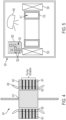
- an enclosure 501 for forming the magnetically permeable material component (e.g., the stator 420 of FIG. 4 ) is provided.
- the enclosure 501 includes a mold 510 that is formed to define a cavity 511 of any shape or size, a conveyance 520 that is configured to introduce an MR fluid 521 into the cavity 511, electromagnetic elements 530 and curing elements 540.
- the MR fluid 521 can include magnetically permeable particles, fibers and/or fillers 522 suspended in a curable liquid 523.
- the electromagnetic elements 530 can include one or more of electromagnetic coils and permanent magnets, for example, and are configured to apply a magnetic field to the MR fluid 521 in the cavity 511 to drive the magnetically permeable particles, fibers and/or fillers 522 into flux line formations.
- the curing elements 540 can include one or more of heat lamps, furnaces or UV lights, for example, to cure the curable liquid 523 into a cured liquid to lock the flux line formations in place.
Landscapes
- Engineering & Computer Science (AREA)
- Power Engineering (AREA)
- Manufacturing & Machinery (AREA)
- Chemical & Material Sciences (AREA)
- Dispersion Chemistry (AREA)
- Manufacture Of Motors, Generators (AREA)
Abstract
Description
- The present disclosure relates to optimal flux path creation with magnetorheological (MR) fluids and, more particularly, to optimal flux path creation with MR fluids for forming uniquely shaped features, such as stators for electric motors, so that solid metal alloys are not needed.
- In electric motors and other devices that make use of magnetic material, magnetic materials are often required for completing magnetic circuits. Typically, these magnetic materials take the form of a solid metal alloy using either a bulk material or laminar sheets to orient and optimize magnetic flux from one location to another location. While these magnetic materials provide benefits in terms of orienting and optimizing magnetic flux, it is often the case that they cannot be easily or reliably formed into complex shapes.
- According to an aspect of the disclosure, a method of forming magnetically permeable material is provided. The method includes introducing magnetorheological (MR) fluid including one or more of magnetically permeable particles, fibers and fillers suspended in a curable liquid into a cavity, driving the magnetically permeable particles, fibers and/or fillers in the MR fluid into flux line formations and curing the curable liquid of the MR fluid during the driving to lock the flux line formations in place.
- In accordance with additional or alternative embodiments, the one or more magnetically permeable particles, fibers and fillers include one or more of cobalt powder particles, fibers and/or fillers, iron-cobalt alloy powder particles, fibers and/or fillers and iron powder particles, fibers and/or fillers.
- In accordance with additional or alternative embodiments, the curable liquid includes one or more of resin and epoxy.
- In accordance with additional or alternative embodiments, the curing includes one or more of heating and irradiating.
- In accordance with additional or alternative embodiments, the cavity has a shape of a stator of an electric motor.
- In accordance with additional or alternative embodiments, the introducing includes assembling a mold defining the cavity and introducing the MR fluid into the cavity via an opening in the mold.
- In accordance with additional or alternative embodiments, the driving of the one or more magnetically permeable particles, fibers and fillers in the MR fluid into the flux line formations includes at least one of activating electromagnetic coils proximate to the MR fluid in the cavity and positioning permanent magnets proximate to the MR fluid in the cavity.
- In accordance with additional or alternative embodiments, the method further includes establishing desired arrangements of the flux line formations and arranging at least one of the electromagnetic coils and the permanent magnets proximate to the MR fluid in the cavity in accordance with the desired arrangements of the flux line formations.
- According to an aspect of the disclosure, a method of forming magnetically permeable material is provided. The method includes suspending one or more magnetically permeable particles, fibers and fillers in a curable liquid to produce a magnetorheological (MR) fluid, introducing the MR fluid into a cavity, applying a magnetic field to the MR fluid in the cavity to drive the one or more magnetically permeable particles, fibers and fillers in the MR fluid into flux line formations and curing the curable liquid of the MR fluid while the applying of the magnetic field to the MR fluid in the cavity continues to lock the flux line formations in place.
- In accordance with additional or alternative embodiments, the one or more magnetically permeable particles, fibers and fillers include one or more of cobalt powder particles, fibers and/or fillers, iron-cobalt alloy powder particles, fibers and/or fillers and iron powder particles, fibers and/or fillers.
- In accordance with additional or alternative embodiments, the curable liquid includes one or more of resin and epoxy.
- In accordance with additional or alternative embodiments, the curing includes one or more of heating and irradiating.
- In accordance with additional or alternative embodiments, the cavity has a shape of a stator of an electric motor.
- In accordance with additional or alternative embodiments, the introducing includes assembling a mold defining the cavity and introducing the MR fluid into the cavity via an opening in the mold.
- In accordance with additional or alternative embodiments, the applying of the magnetic field to the MR fluid in the cavity includes at least one of activating electromagnetic coils proximate to the MR fluid in the cavity and positioning permanent magnets proximate to the MR fluid in the cavity.
- In accordance with additional or alternative embodiments, the method further includes establishing desired arrangements of the flux line formations and arranging at least one of the electromagnetic coils and the permanent magnets proximate to the MR fluid in the cavity in accordance with the desired arrangements of the flux line formations.
- According to an aspect of the disclosure, a magnetically permeable material component is provided. The magnetically permeable material component includes a cured liquid and one or more magnetically permeable particles, fibers and fillers formed into flux line formations locked in place by the cured liquid.
- In accordance with additional or alternative embodiments, the cured liquid includes at least one of a cured resin and a cured epoxy and the one or more magnetically permeable particles, fibers and fillers include one or more of cobalt powder particles, fibers and/or fillers, iron-cobalt alloy powder particles, fibers and/or fillers and iron powder particles, fibers and/or fillers.
- In accordance with additional or alternative embodiments, an electric motor is provided and includes a rotor, a stator provided as the magnetically permeable material component and windings wound on teeth of the stator. The windings are configured to generate flux to drive rotations of the rotor when current is applied thereto.
- In accordance with additional or alternative embodiments, an enclosure is provided for forming the magnetically permeable material component. The enclosure includes a mold defining a cavity, a conveyance configured to introduce a magnetorheological (MR) fluid including the one or more magnetically permeable particles, fibers and fillers suspended in a curable liquid into the cavity, electromagnetic elements configured to apply a magnetic field to the MR fluid in the cavity to drive the one or more magnetically permeable particles, fibers and fillers in the MR fluid into the flux line formations and curing elements to cure the curable liquid of the MR fluid into the cured liquid.
- Additional features and advantages are realized through the techniques of the present disclosure. Other embodiments and aspects of the disclosure are described in detail herein and are considered a part of the claimed technical concept. For a better understanding of the disclosure with the advantages and the features, refer to the description and to the drawings.
- For a more complete understanding of this disclosure, reference is now made to the following brief description, taken in connection with the accompanying drawings and detailed description, wherein like reference numerals represent like parts:
-
FIG. 1 is a flow diagram illustrating a method of forming magnetically permeable material in accordance with embodiments; -
FIG. 2 is a flow diagram illustrating a method of forming magnetically permeable material in accordance with further embodiments; -
FIG. 3 is a graphical illustration of the methods ofFIGS. 1 and 2 in accordance with embodiments; -
FIG. 4 is a schematic illustration of an electric motor including a stator or component that is formed of magnetically permeable material in accordance with embodiments; and -
FIG. 5 is a schematic illustration of an enclosure for forming the stator or component formed of the magnetically permeable material ofFIG. 4 in accordance with embodiments. - As will be described below, magnetorheological (MR) fluids are used to create optimal magnetic flux paths for applications, such as uniquely shaped stators for electric motors, without using solid metal alloys. The MR fluid is produced by the magnetic permeable powders, such as cobalt powder, iron-cobalt alloy powder, iron powder or any other highly magnetic permeable powder including fibers and fillers for reducing weight of components, being provided in a curable liquid, such as a resin or another viscous liquid to be determined based on the application. The MR fluid can then be inserted or injected into a cavity of any shape or size (i.e., a cavity in the shape of a stator). Using electromagnetic coils and super magnets, flux lines formed of particles, fibers and/or fillers of the magnetic permeable powder are created in the MR fluid. These flux lines are then effectively frozen in place by the liquid being cured or otherwise hardened into a solid.
- With reference to
FIG. 1 , amethod 100 of forming magnetically permeable material is provided. The method 1000 includes introducing magnetorheological (MR) fluid into a cavity of any shape or size (101), where the MR fluid includes magnetically permeable particles, magnetically permeable fibers and/or magnetically permeable fillers suspended in a curable liquid. Themethod 100 further includes driving the magnetically permeable particles, the magnetically permeable fibers and/or the magnetically permeable fillers in the MR fluid into flux line formations (102) and curing the curable liquid of the MR fluid during the driving to lock the flux line formations in place (103). - With reference to
FIGS. 2 and3 , amethod 200 of forming magnetically permeable material is provided. Themethod 200 includes suspending magnetically permeable particles, magnetically permeable fibers and/or magnetically permeable fillers (hereinafter referred to as "magnetically permeable particles, fibers and/or fillers") 301 in acurable liquid 302 to produce a magnetorheological (MR) fluid 303 (201). The magnetically permeable particles, fibers and/orfillers 301 can include one or more of cobalt powder particles, fibers and/or fillers, iron-cobalt alloy powder particles, fibers and/or fillers, iron powder particles, fibers and/or fillers and other similar types of powders, particles, fibers and/or fillers. Thecurable liquid 302 can include one or more of resin and epoxy and can be cured by application of heat, radiation (e.g., ultraviolet (UV) radiation) or other similar external stimuli. Themethod 200 further includes introducing theMR fluid 303 into acavity 310 of any shape or size (202), applying a magnetic field to theMR fluid 303 in thecavity 310 to drive the magnetically permeable particles, fibers and/orfillers 301 in theMR fluid 303 into flux line formations 320 (203). Themethod 200 also includes curing thecurable liquid 302 of theMR fluid 303 while the applying of the magnetic field to theMR fluid 303 in thecavity 310 continues to thereby lock theflux line formations 320 in place (204) and optionally removing the mold 330 (see below) from theMR fluid 303 with thecurable liquid 302 in a cured condition (205). The curing ofoperation 204 can be executed by use ofcuring elements 340, such as a heat element or a UV light. - In accordance with embodiments, the
cavity 310 can have any shape or size including, for example, a shape of a stator of an electric motor as discussed in further detail below. - As shown in
FIGS. 2 and3 , the introducing ofoperation 202 can include assembling amold 330 which is formed to define the cavity 310 (2021) and introducing theMR fluid 303 into thecavity 310 via anopening 331 in the mold 330 (2022). Also, the applying of the magnetic field to theMR fluid 303 in thecavity 310 ofoperation 203 can include at least one of activatingelectromagnetic coils 341, which are disposed proximate to theMR fluid 303 in thecavity 310, and positioningpermanent magnets 342, which are disposed proximate to theMR fluid 303 in thecavity 310. In either case, the method can optionally include establishing desired arrangements of the flux line formations 320 (2031) and arranging at least one of theelectromagnetic coils 341 and thepermanent magnets 342 proximate to theMR fluid 303 in thecavity 310 in accordance with the desired arrangements of the flux line formations 320 (2032). In other words, the placements of the at least one of theelectromagnetic coils 341 and thepermanent magnets 342 are such that theflux line formations 320 being formed are formed in a desired configuration. This desired configuration can, for example, be intended to promote optimized flux line generation in and through a stator during an operation of an electric motor including the stator. - With reference to
FIG. 4 , anelectric motor 401 is provided and includes arotor 410, which is rotatable about a rotational axis thereof, astator 420 andwindings 430. Thestator 420 includes anannular body 421 andteeth 422 extending radially from theannular body 421. Thewindings 430 are wound on theteeth 422 and are configured to generate flux to drive rotations of therotor 410 when current is applied to thewindings 430. At least a portion of thestator 420 can be provided as a magnetically permeable material component that includes a cured liquid as in the curable liquid described above with reference toFIGS. 2 and3 and the magnetically permeable particles, fibers and/or fillers formed into the flux line formations that are locked in place by the cured liquid as described above with reference toFIGS. 2 and3 . Again, as above, the cured liquid can include at least one of a cured resin and a cured epoxy and the magnetically permeable particles, fibers and/or fillers include one or more of cobalt powder particles, fibers and/or fillers, iron-cobalt alloy powder particles, fibers and/or fillers, iron powder particles, fibers and/or fillers and other similar types of powders, particles, fibers and/or fillers. - With reference to
FIG. 5 , anenclosure 501 for forming the magnetically permeable material component (e.g., thestator 420 ofFIG. 4 ) is provided. Theenclosure 501 includes amold 510 that is formed to define acavity 511 of any shape or size, aconveyance 520 that is configured to introduce anMR fluid 521 into thecavity 511,electromagnetic elements 530 and curingelements 540. As described above, theMR fluid 521 can include magnetically permeable particles, fibers and/orfillers 522 suspended in acurable liquid 523. Theelectromagnetic elements 530 can include one or more of electromagnetic coils and permanent magnets, for example, and are configured to apply a magnetic field to theMR fluid 521 in thecavity 511 to drive the magnetically permeable particles, fibers and/orfillers 522 into flux line formations. The curingelements 540 can include one or more of heat lamps, furnaces or UV lights, for example, to cure thecurable liquid 523 into a cured liquid to lock the flux line formations in place. - Technical effects and benefits of the present disclosure are the provision of new out-of-the-box motor designs with high efficiency and the ease of cooling to eliminate Eddy current heating. The use of MR fluids in the present disclosure opens the door to unique designs which could not be created previously due to limitations of solid metal laminate sheets or any solid metal alloys. It also allows for the optimization of magnetic flux lines/planes in any shape to complete magnetic circuits.
- The corresponding structures, materials, acts, and equivalents of all means or step plus function elements in the claims below are intended to include any structure, material, or act for performing the function in combination with other claimed elements as specifically claimed. The description of the present disclosure has been presented for purposes of illustration and description, but is not intended to be exhaustive or limited to the technical concepts in the form disclosed. Many modifications and variations will be apparent to those of ordinary skill in the art without departing from the scope and spirit of the disclosure. The embodiments were chosen and described in order to best explain the principles of the disclosure and the practical application, and to enable others of ordinary skill in the art to understand the disclosure for various embodiments with various modifications as are suited to the particular use contemplated.
- While the preferred embodiments to the disclosure have been described, it will be understood that those skilled in the art, both now and in the future, may make various improvements and enhancements which fall within the scope of the claims which follow. These claims should be construed to maintain the proper protection for the disclosure first described.
Claims (15)
- A method of forming magnetically permeable material, the method comprising:introducing magnetorheological (MR) fluid comprising one or more of magnetically permeable particles, fibers and fillers suspended in a curable liquid into a cavity;driving the magnetically permeable particles, fibers and/or fillers in the MR fluid into flux line formations; andcuring the curable liquid of the MR fluid during the driving to lock the flux line formations in place.
- The method according to claim 1, wherein the one or more magnetically permeable particles, fibers and fillers comprise one or more of cobalt powder particles, fibers and/or fillers, iron-cobalt alloy powder particles, fibers and/or fillers and iron powder particles, fibers and/or fillers.
- The method according to claim 1 or 2, wherein the curable liquid comprises one or more of resin and epoxy.
- The method according to any of claims 1 to 3, wherein the curing comprises one or more of heating and irradiating.
- The method according to any of claims 1 to 4, wherein the cavity has a shape of a stator of an electric motor.
- The method according to any of claims 1 to 5, wherein the introducing comprises:assembling a mold defining the cavity; andintroducing the MR fluid into the cavity via an opening in the mold.
- The method according to any of claims 1 to 6, wherein the driving of the one or more magnetically permeable particles, fibers and fillers in the MR fluid into the flux line formations comprises at least one of:activating electromagnetic coils proximate to the MR fluid in the cavity; andpositioning permanent magnets proximate to the MR fluid in the cavity.
- The method according to claim 7, further comprising:establishing desired arrangements of the flux line formations; andarranging at least one of the electromagnetic coils and the permanent magnets proximate to the MR fluid in the cavity in accordance with the desired arrangements of the flux line formations.
- A method of forming magnetically permeable material, the method comprising:suspending one or more magnetically permeable particles, fibers and fillers in a curable liquid to produce a magnetorheological (MR) fluid;introducing the MR fluid into a cavity;applying a magnetic field to the MR fluid in the cavity to drive the one or more magnetically permeable particles, fibers and fillers in the MR fluid into flux line formations; andcuring the curable liquid of the MR fluid while the applying of the magnetic field to the MR fluid in the cavity continues to lock the flux line formations in place.
- The method according to claim 9, wherein the one or more magnetically permeable particles, fibers and fillers comprise one or more of cobalt powder particles, fibers and/or fillers, iron-cobalt alloy powder particles, fibers and/or fillers and iron powder particles, fibers and/or fillers, and/or
wherein the curable liquid comprises one or more of resin and epoxy, and/or wherein the curing comprises one or more of heating and irradiating, and/or wherein the cavity has a shape of a stator of an electric motor. - The method according to claim 9 or 10, wherein the introducing comprises:assembling a mold defining the cavity; andintroducing the MR fluid into the cavity via an opening in the mold,and/or, wherein the applying of the magnetic field to the MR fluid in the cavity comprises at least one of:activating electromagnetic coils proximate to the MR fluid in the cavity; andpositioning permanent magnets proximate to the MR fluid in the cavity,wherein optionally, the method further comprises:establishing desired arrangements of the flux line formations; andarranging at least one of the electromagnetic coils and the permanent magnets proximate to the MR fluid in the cavity in accordance with the desired arrangements of the flux line formations.
- A magnetically permeable material component, comprising:a cured liquid; andone or more magnetically permeable particles, fibers and fillers formed into flux line formations locked in place by the cured liquid.
- The magnetically permeable component according to claim 12, wherein:the cured liquid comprises at least one of a cured resin and a cured epoxy, andthe one or more magnetically permeable particles, fibers and fillers comprise one or more of cobalt powder particles, fibers and/or fillers, iron-cobalt alloy powder particles, fibers and/or fillers and iron powder particles, fibers and/or fillers.
- An electric motor, comprising:a rotor;a stator provided as the magnetically permeable material component according to claim 12; andwindings wound on teeth of the stator, the windings being configured to generate flux to drive rotations of the rotor when current is applied thereto.
- An enclosure for forming the magnetically permeable material component according to claim 12, the enclosure comprising:a mold defining a cavity;a conveyance configured to introduce a magnetorheological (MR) fluid comprising the one or more magnetically permeable particles, fibers and fillers suspended in a curable liquid into the cavity;electromagnetic elements configured to apply a magnetic field to the MR fluid in the cavity to drive the one or more magnetically permeable particles, fibers and fillers in the MR fluid into the flux line formations; andcuring elements to cure the curable liquid of the MR fluid into the cured liquid.
Applications Claiming Priority (1)
| Application Number | Priority Date | Filing Date | Title |
|---|---|---|---|
| US17/474,661 US11742731B2 (en) | 2021-09-14 | 2021-09-14 | Method of forming magnetic flux optimization for uniquely shaped designs |
Publications (1)
| Publication Number | Publication Date |
|---|---|
| EP4148750A1 true EP4148750A1 (en) | 2023-03-15 |
Family
ID=83318725
Family Applications (1)
| Application Number | Title | Priority Date | Filing Date |
|---|---|---|---|
| EP22195392.0A Pending EP4148750A1 (en) | 2021-09-14 | 2022-09-13 | Magnetic flux optimization for uniquely shaped designs |
Country Status (2)
| Country | Link |
|---|---|
| US (1) | US11742731B2 (en) |
| EP (1) | EP4148750A1 (en) |
Citations (3)
| Publication number | Priority date | Publication date | Assignee | Title |
|---|---|---|---|---|
| US20140376837A1 (en) * | 2013-06-24 | 2014-12-25 | The Regents Of The University Of California | Semi-active insolators based on magnetorheological nanocomposites |
| EP3474297A1 (en) * | 2017-10-02 | 2019-04-24 | United Technologies Corporation | Direct writing of conformal and free-form magnets |
| CN110229469A (en) * | 2019-06-14 | 2019-09-13 | 清华大学深圳研究生院 | Dielectric gradient material and its application |
Family Cites Families (6)
| Publication number | Priority date | Publication date | Assignee | Title |
|---|---|---|---|---|
| US5984056A (en) | 1997-04-24 | 1999-11-16 | Bell Helicopter Textron Inc. | Magnetic particle damper apparatus |
| JP4626382B2 (en) | 2005-04-28 | 2011-02-09 | 株式会社デンソー | Electric motor |
| US20100256791A1 (en) * | 2009-04-06 | 2010-10-07 | Gm Global Technology Operations, Inc. | Method and apparatus for the three-dimensional shape magnetic forming of a motor core |
| KR101317892B1 (en) | 2011-01-24 | 2013-10-16 | 주식회사 아모텍 | Amorphous Stator and Producing Method thereof |
| US10663020B2 (en) | 2015-03-12 | 2020-05-26 | Lord Corporation | Dual rotor torque generating devices, systems, and methods |
| US20170126087A1 (en) * | 2015-10-30 | 2017-05-04 | Rod F. Soderberg | Device including material originating from magnetic particles providing structural and magnetic capabilities |
-
2021
- 2021-09-14 US US17/474,661 patent/US11742731B2/en active Active
-
2022
- 2022-09-13 EP EP22195392.0A patent/EP4148750A1/en active Pending
Patent Citations (3)
| Publication number | Priority date | Publication date | Assignee | Title |
|---|---|---|---|---|
| US20140376837A1 (en) * | 2013-06-24 | 2014-12-25 | The Regents Of The University Of California | Semi-active insolators based on magnetorheological nanocomposites |
| EP3474297A1 (en) * | 2017-10-02 | 2019-04-24 | United Technologies Corporation | Direct writing of conformal and free-form magnets |
| CN110229469A (en) * | 2019-06-14 | 2019-09-13 | 清华大学深圳研究生院 | Dielectric gradient material and its application |
Also Published As
| Publication number | Publication date |
|---|---|
| US11742731B2 (en) | 2023-08-29 |
| US20230083543A1 (en) | 2023-03-16 |
Similar Documents
| Publication | Publication Date | Title |
|---|---|---|
| JP5900528B2 (en) | Internal magnet type inner rotor manufacturing equipment | |
| CN1825737B (en) | permanent magnet type rotary machine | |
| Liu et al. | Modular reluctance network simulation of a linear permanent-magnet vernier machine using new mesh generation methods | |
| US20240146170A1 (en) | Electromagnetic Halbach array, devices, and methods | |
| CN105939067B (en) | Rotating electric machine and current input control method of rotating electric machine | |
| CN109690911A (en) | Motor | |
| CN107925329A (en) | motor rotor | |
| JP2012115138A (en) | Permanent magnet rotors and methods of manufacturing the same | |
| US10734848B2 (en) | Fixtures and methods for forming aligned magnetic cores | |
| JP2003111322A (en) | Permanent magnet machine rotor | |
| US20220045582A1 (en) | Method of manufacturing a three-dimensional flux structure for circumferential flux machines | |
| US20140062247A1 (en) | Electric machine with base element | |
| US20190238016A1 (en) | Rotor for an electric machine, electric machine with the rotor and to method for producing the rotor | |
| Li et al. | Pole-changing flux-weakening DC-excited dual-memory machines for electric vehicles | |
| EP2659575B1 (en) | Magnetizer and assembler for electrical machines | |
| US11742731B2 (en) | Method of forming magnetic flux optimization for uniquely shaped designs | |
| CN101958174A (en) | The In-situ Magnetization device | |
| Yang et al. | Design and control of the 3 degrees of freedom actuator by controlling the electromagnetic force | |
| CN105449889A (en) | Armature of permanent magnet excitation with guided magnetic field | |
| BRPI0615441A2 (en) | device and method for holding and locking permanent magnets and improving cooling within a rotary electric machine | |
| JP2011259593A (en) | Insulator and method of forming the same | |
| Weiduo et al. | Electromagnetic shields of the air-core compulsator | |
| US20190148994A1 (en) | Fixtures and methods for forming aligned magnetic cores | |
| Takbash et al. | Torque ripple reduction of a variable flux motor | |
| JPH0993845A (en) | Surface magnet type rotor |
Legal Events
| Date | Code | Title | Description |
|---|---|---|---|
| PUAI | Public reference made under article 153(3) epc to a published international application that has entered the european phase |
Free format text: ORIGINAL CODE: 0009012 |
|
| STAA | Information on the status of an ep patent application or granted ep patent |
Free format text: STATUS: THE APPLICATION HAS BEEN PUBLISHED |
|
| AK | Designated contracting states |
Kind code of ref document: A1 Designated state(s): AL AT BE BG CH CY CZ DE DK EE ES FI FR GB GR HR HU IE IS IT LI LT LU LV MC MK MT NL NO PL PT RO RS SE SI SK SM TR |
|
| STAA | Information on the status of an ep patent application or granted ep patent |
Free format text: STATUS: REQUEST FOR EXAMINATION WAS MADE |
|
| 17P | Request for examination filed |
Effective date: 20230914 |
|
| RBV | Designated contracting states (corrected) |
Designated state(s): AL AT BE BG CH CY CZ DE DK EE ES FI FR GB GR HR HU IE IS IT LI LT LU LV MC MK MT NL NO PL PT RO RS SE SI SK SM TR |