EP4148674A1 - Accuracy verification of a perception system of a vehicle - Google Patents
Accuracy verification of a perception system of a vehicle Download PDFInfo
- Publication number
- EP4148674A1 EP4148674A1 EP22194897.9A EP22194897A EP4148674A1 EP 4148674 A1 EP4148674 A1 EP 4148674A1 EP 22194897 A EP22194897 A EP 22194897A EP 4148674 A1 EP4148674 A1 EP 4148674A1
- Authority
- EP
- European Patent Office
- Prior art keywords
- perception
- target
- pose
- sensor
- vehicle
- Prior art date
- Legal status (The legal status is an assumption and is not a legal conclusion. Google has not performed a legal analysis and makes no representation as to the accuracy of the status listed.)
- Granted
Links
Images


Classifications
-
- G—PHYSICS
- G06—COMPUTING OR CALCULATING; COUNTING
- G06T—IMAGE DATA PROCESSING OR GENERATION, IN GENERAL
- G06T7/00—Image analysis
- G06T7/80—Analysis of captured images to determine intrinsic or extrinsic camera parameters, i.e. camera calibration
-
- B—PERFORMING OPERATIONS; TRANSPORTING
- B60—VEHICLES IN GENERAL
- B60W—CONJOINT CONTROL OF VEHICLE SUB-UNITS OF DIFFERENT TYPE OR DIFFERENT FUNCTION; CONTROL SYSTEMS SPECIALLY ADAPTED FOR HYBRID VEHICLES; ROAD VEHICLE DRIVE CONTROL SYSTEMS FOR PURPOSES NOT RELATED TO THE CONTROL OF A PARTICULAR SUB-UNIT
- B60W60/00—Drive control systems specially adapted for autonomous road vehicles
- B60W60/001—Planning or execution of driving tasks
-
- G—PHYSICS
- G06—COMPUTING OR CALCULATING; COUNTING
- G06V—IMAGE OR VIDEO RECOGNITION OR UNDERSTANDING
- G06V20/00—Scenes; Scene-specific elements
- G06V20/50—Context or environment of the image
- G06V20/56—Context or environment of the image exterior to a vehicle by using sensors mounted on the vehicle
- G06V20/58—Recognition of moving objects or obstacles, e.g. vehicles or pedestrians; Recognition of traffic objects, e.g. traffic signs, traffic lights or roads
-
- B—PERFORMING OPERATIONS; TRANSPORTING
- B60—VEHICLES IN GENERAL
- B60W—CONJOINT CONTROL OF VEHICLE SUB-UNITS OF DIFFERENT TYPE OR DIFFERENT FUNCTION; CONTROL SYSTEMS SPECIALLY ADAPTED FOR HYBRID VEHICLES; ROAD VEHICLE DRIVE CONTROL SYSTEMS FOR PURPOSES NOT RELATED TO THE CONTROL OF A PARTICULAR SUB-UNIT
- B60W2420/00—Indexing codes relating to the type of sensors based on the principle of their operation
- B60W2420/40—Photo, light or radio wave sensitive means, e.g. infrared sensors
- B60W2420/403—Image sensing, e.g. optical camera
-
- B—PERFORMING OPERATIONS; TRANSPORTING
- B60—VEHICLES IN GENERAL
- B60W—CONJOINT CONTROL OF VEHICLE SUB-UNITS OF DIFFERENT TYPE OR DIFFERENT FUNCTION; CONTROL SYSTEMS SPECIALLY ADAPTED FOR HYBRID VEHICLES; ROAD VEHICLE DRIVE CONTROL SYSTEMS FOR PURPOSES NOT RELATED TO THE CONTROL OF A PARTICULAR SUB-UNIT
- B60W2420/00—Indexing codes relating to the type of sensors based on the principle of their operation
- B60W2420/40—Photo, light or radio wave sensitive means, e.g. infrared sensors
- B60W2420/408—Radar; Laser, e.g. lidar
-
- B—PERFORMING OPERATIONS; TRANSPORTING
- B60—VEHICLES IN GENERAL
- B60W—CONJOINT CONTROL OF VEHICLE SUB-UNITS OF DIFFERENT TYPE OR DIFFERENT FUNCTION; CONTROL SYSTEMS SPECIALLY ADAPTED FOR HYBRID VEHICLES; ROAD VEHICLE DRIVE CONTROL SYSTEMS FOR PURPOSES NOT RELATED TO THE CONTROL OF A PARTICULAR SUB-UNIT
- B60W2554/00—Input parameters relating to objects
- B60W2554/40—Dynamic objects, e.g. animals, windblown objects
- B60W2554/404—Characteristics
- B60W2554/4048—Field of view, e.g. obstructed view or direction of gaze
-
- G—PHYSICS
- G06—COMPUTING OR CALCULATING; COUNTING
- G06T—IMAGE DATA PROCESSING OR GENERATION, IN GENERAL
- G06T2207/00—Indexing scheme for image analysis or image enhancement
- G06T2207/10—Image acquisition modality
- G06T2207/10016—Video; Image sequence
-
- G—PHYSICS
- G06—COMPUTING OR CALCULATING; COUNTING
- G06T—IMAGE DATA PROCESSING OR GENERATION, IN GENERAL
- G06T2207/00—Indexing scheme for image analysis or image enhancement
- G06T2207/30—Subject of image; Context of image processing
- G06T2207/30248—Vehicle exterior or interior
- G06T2207/30252—Vehicle exterior; Vicinity of vehicle
Definitions
- the method 400 includes, at 402, causing the vehicle to traverse a path around a target that is fixed in an environment.
- the target has a known pose.
- the path is configured so that the target comes into a respective field of view (FOV) of each respective perception sensor of the one or more perception sensors along the path.
- FOV field of view
- FIG. 4 provides a particular method of verifying accuracy of a perception system of a vehicle according to some embodiments. Other sequences of steps may also be performed according to alternative embodiments. For example, alternative embodiments of the present invention may perform the steps outlined above in a different order. Moreover, the individual steps illustrated in FIG. 4 may include multiple sub-steps that may be performed in various sequences as appropriate to the individual step. Furthermore, additional steps may be added and some steps may be removed depending on the particular applications. One of ordinary skill in the art would recognize many variations, modifications, and alternatives.
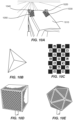
- FIG. 10B - 10E show some exemplary types of targets that can be used.
- FIG. 10B shows a corner reflector that can be used as a target. The corner reflector can return a strong signal to radar sensors, allowing for accurate detection.
- FIG. 10C shows a ChArUco board that can be used as a target. The ChArUco board combines a chessboard with ArUco markers. The ArUco markers allow fast and versatile detection, while the chessboard allows accurate position measurements.
- FIG. 10D shows a cube with checkerboards that can be used as a target.
- FIG. 10E shows an icosahedron with deltille grids that can be used as a target. Other types of targets that allow accurate position measurements can also be used.
- One of ordinary skill in the art would recognize many variations, alternatives, and modifications.
- a first target 1150 and a second target 1160 can be installed at the two front corners of the engine hood 1118, so that they are in the FOV 1122 of the first perception sensor 1120.
- a third target 1170 can be installed on the left boom 1114, so that it is in the FOV 1132 of the second perception sensor 1130.
- a fourth target 1180 can be installed on the right boom 1112, so that it is in the FOV 1142 of the third perception sensor 1140.
- the first perception sensor 1120 can measure a pose of each the first target 1150 and the second target 1160, and compare the measured pose with a first reference pose and a second reference pose, respectively.
- the second perception sensor 1130 can measure a pose of the third target 1170, and compare the measured pose with a third reference pose.
- the third perception sensor 1140 can measure a pose of the fourth target 1180, and compare the measured pose with a fourth reference pose.
Landscapes
- Engineering & Computer Science (AREA)
- Physics & Mathematics (AREA)
- General Physics & Mathematics (AREA)
- Theoretical Computer Science (AREA)
- Automation & Control Theory (AREA)
- Human Computer Interaction (AREA)
- Transportation (AREA)
- Mechanical Engineering (AREA)
- Multimedia (AREA)
- Computer Vision & Pattern Recognition (AREA)
- Navigation (AREA)
Abstract
Description
- An autonomous or semi-autonomous vehicle can be equipped with a perception system for detecting objects in its environment. The perception system can include perception sensors, such as radars, LiDARs, cameras, and the like. The perception sensors can acquire three-dimensional images (e.g., point clouds) and/or two-dimensional images of the environment within their fields of view. For example, a point cloud representing the objects in the environment, such as other vehicles, pedestrians, street signs, and buildings, can be constructed based on the images acquired by the perception sensors. The point cloud can be used to assist the navigation of the autonomous vehicle so as to avoid collision with obstacles. For example, if a pedestrian is detected in front of the vehicle, the autonomous vehicle can apply its brake to cause the vehicle to slow down or stop.
- Safe operation of an autonomous vehicle can rely on the accuracy of the perception system. The perception sensors can be initially installed on the autonomous vehicle at the desired locations with the desired orientations. The position and the orientation of each perception sensor can be calibrated with respect to the vehicle. Such calibration can be performed, for example, in a manufacturer's plant or when the perception system is installed. Accurate calibrations can ensure that the image or point cloud acquired by the perception system represents the objects relative to the vehicle accurately. However, during maintenance, storage, and transport, the perception sensors can become damaged or misaligned. For example, a minor crash (e.g., hitting a tree branch) can possibly cause a perception sensor to move from its previously calibrated position. Therefore, it can be important to verify the accuracy of the perception system before activating the perception system for navigating the autonomous vehicle.
- According to some embodiments, a method of verifying accuracy of a perception system of a vehicle includes causing the vehicle to traverse a path around a target that is fixed in an environment. The target has a known pose. The path is configured so that the target comes into a respective field of view (FOV) of each respective perception sensor of one or more perception sensors of the perception system along the path. The method further includes, for each respective perception sensor of the one or more perception sensors, while the target is within the respective FOV of the respective perception sensor, acquiring a respective image of the target using the respective perception sensor; at the perception system, determining a respective pose of the target based on the respective image; and at a computer system communicatively coupled with the perception system, determining whether the respective pose matches the known pose of the target.
- According to some embodiments, a method of verifying accuracy of a perception system of a vehicle includes, for each respective perception sensor of one or more perception sensors of the perception system: moving a target to a respective location that is within a respective field of view (FOV) of the respective perception sensor; acquiring a respective image of the target using the respective perception sensor while the target is at the respective location; at the perception system, determining a respective pose of the target based on the respective image; determining a respective reference pose of the target while the target is at the respective location using a positioning solution attached to the target; and at a computer system communicatively coupled to the perception system and the positioning solution, determining whether the respective pose matches the respective reference pose.
-
-
FIG. 1 illustrates a vehicle that is equipped with multiple perception sensors. -
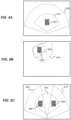
FIGS. 2A and 2B illustrate a method of verifying accuracy of a perception system of a vehicle according to some embodiments. -
FIG. 3 shows an exemplary graphic user interface (GUI) of an application for verifying accuracy of a perception system of a vehicle according to some embodiments. -
FIG. 4 shows a simplified flowchart illustrating a method of verifying accuracy of a perception system of a vehicle according to some embodiments. -
FIG. 5 illustrates a method of verifying accuracy of a perception system of a vehicle according to some embodiments. -
FIG. 6 shows an exemplary GUI of an application for verifying the accuracy of a perception system of a vehicle according to some embodiments. -
FIG. 7 shows a simplified flowchart illustrating a method of verifying accuracy of a perception system of a vehicle according to some embodiments. -
FIGS. 8A and 8B illustrate two examples in which perception sensors are mounted on articulated segments of a vehicle according to some embodiments. -
FIGS. 9A - 9C illustrate some examples in which accuracies of perception sensors can be verified by correlating the sensor data of different perception sensors according to some embodiments. -
FIG. 10A illustrates an example of using targets installed on a vehicle to verify the accuracy of a perception system of the vehicle according to some embodiments. -
FIG. 10B - 10E show some exemplary types of targets that can be used for verify the accuracy of a perception system of the vehicle according to some embodiments. -
FIG. 11 illustrates an example of using targets installed on a vehicle to verify the accuracy of a perception system of the vehicle according to some embodiments. -
FIG. 12 shows an exemplary block diagram of a perception system test system according to some embodiments. - Embodiments of the present invention provide methods of verifying accuracy of a perception system of a vehicle.
FIG. 1 illustrates avehicle 110 that is equipped with multiple perception sensors. For example, afirst perception sensor 120 can be mounted in the front of the vehicle 110 (e.g., on the front bumper or front windshield), so that its field of view (FOV) 122 is directed toward the front. Asecond perception sensor 130 can be mounted at the rear of the vehicle 110 (e.g., on the rear bumper or rear windshield), so that its FOV 132 is directed toward the rear. Athird perception sensor 140 can be mounted on the right side of thevehicle 110, so that its FOV 142 is directed toward the right. Afourth perception sensor 150 can be mounted on the left side of thevehicle 110, so that its FOV 152 is directed toward the left. Thevehicle 110 can include additional perception sensors. Some perception sensors can have overlapping FOVs. Also, some perception sensors can have a 360-degree FOV (e.g., a rotating LiDAR). Thevehicle 110 can be an autonomous vehicle or a semi-autonomous vehicle (which can be referred to herein as an autonomous vehicle). - Each of the
perception sensors perception sensors respective FOV perception sensors vehicle 110 that can detect objects in the environment surrounding thevehicle 110. The sensor data acquired by theperception sensors vehicle 110. - Each
perception sensor vehicle 110. Thus, if the LiDAR sensor has moved from its calibrated position, the resulting point cloud can represent objects' positions incorrectly. - According to some embodiments, methods are provided to verifying the accuracy of each perception sensor of a perception system of a vehicle. These methods can involve bringing a target with a known pose (including position and orientation) into the FOV of each perception sensor, and verify that each perception sensor detects the target at the correct pose. In some embodiments, the vehicle can traverse a predetermined path around a fixed target with a known pose, so that the fixed target comes into the FOV of each perception sensor for at least a portion of the path. The pose measured by each perception sensor can be compared to the known pose to determine whether each perception sensor is correctly aligned. In some other embodiments, a target equipped with a high accuracy position solution (e.g., a GNSS) can be moved around the vehicle into the FOV of each perception sensor. The pose measured by each perception sensor can be compared to the pose measured by the high accuracy position solution to determine whether each perception sensor is correctly aligned. Various embodiments are described in more detail below.
-
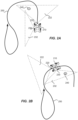
FIGS. 2A and 2B illustrate a method of verifying accuracy of a perception system of avehicle 210 according to some embodiments. The perception system of thevehicle 210 includes multiple perception sensors mounted at various locations on thevehicle 210. For simplicity, only twoperception sensors FIGS. 2A and 2B . As illustrated, the twoperception sensors vehicle 210, respectively. Thevehicle 210 can include more than two perception sensors so that their combined FOV covers the entire surrounding of thevehicle 210. - As illustrated in
FIGS. 2A and 2B , there is atarget 240 that is fixed in the environment. Thetarget 240 can, for example, include a tree, a street sign, or the like. Thetarget 240 can be previously surveyed, so that its pose (including its position and orientation) can be accurately known. To verify the accuracies of theperception sensors predetermined path 250. Thevehicle 210 can be driven by a human operator, or can be driven using an automated steering system (but under the supervision of a human operator, as the accuracy of the perception system has not yet been verified). - The
path 250 can be designed so that all perception sensors would "see" the target at certain ranges and angles along thepath 250. That is, the fixedtarget 240 would come into the FOV of each of the perception sensors (including thefirst perception sensor 220 and thesecond perception sensor 230, as well as other perception sensors not shown) along thepath 250. For example, when thevehicle 210 is at a first position along thepath 250 as illustrated inFIG. 2A , the fixedtarget 240 is within theFOV 222 of thefirst perception sensor 220; and when thevehicle 210 is at a second position along thepath 250 as illustrated inFIG. 2B , the fixedtarget 240 is within theFOV 232 of thesecond perception sensor 230. - When the
vehicle 210 is at the first position shown inFIG. 2A , thefirst perception sensor 220 can acquire a first image of thetarget 240, and determine a first pose thetarget 240 based on the first image. The first pose can be compared with the known pose of the target. If the first pose matches with the known pose within a threshold (for example 5%, or an absolute value), it can be determined that thefirst perception sensor 220 is correctly aligned. Similarly, when thevehicle 210 is at the second position shown inFIG. 2B , thesecond perception sensor 230 can acquire a second image of thetarget 240, and determine a second pose of thetarget 240 based on the second image. The second pose can be compared with the known pose. If the second pose matches with the known pose within the threshold, it can be determined that thesecond perception sensor 230 is correctly aligned. - It may be advantageous to design the
path 250 so that the pose of thetarget 240 can be measured when thetarget 240 is in both the near field and the far field of each perception sensor. In some embodiments, each perception sensor can acquire a sequence of images (e.g., a sequence of video frames) of thetarget 240 when thetarget 240 is within its FOV. The movement of thetarget 240 with respect to thevehicle 210 can be determined from the sequence of images. The movement can then be compared with an expected movement (e.g., a previously recorded movement) to determine whether they match with each other. This would provide an additional verification of the accuracy of the perception sensors. - According to some embodiments, the process of verifying the accuracy of the perception system can be managed by an application running on an operator's device (e.g., a portable computer device or a computer device installed in the dashboard of the vehicle).
FIG. 3 shows an exemplary graphic user interface (GUI) 310 of the application according to some embodiments. For example, in thedisplay area 320, afirst target 330 and asecond target 340 are shown to be currently within afirst FOV 350 of a first perception sensor (e.g., a LiDAR). The known positions of thefirst target 330 and the second target 340 (e.g., determined from previous surveys) are shown as shaded circles. The detected positions of thefirst target 330 and thesecond target 340 as measured by the first perception sensor are shown as the solid circles. If the detected positions of thefirst target 330 and thesecond target 340 match the known positions of thefirst target 330 and thesecond target 340, respectively, it can be determined that the first perception sensor passes the test. - In another
display area 360, the status of various perception sensors can be shown. For example, a green circle can indicate that the perception sensor passes the test, and a red triangle can indicate that the perception sensor does not pass the test. Therefore, an operator can take necessary actions accordingly to correct the alignments of those perceptions sensors that do not pass the test. In some embodiments, when all the perception sensors pass the test, the perception system can be activated for navigation of the vehicle. -
FIG. 4 shows a simplified flowchart illustrating amethod 400 of verifying accuracy of a perception system of a vehicle according to some embodiments. The perception system includes one or more perception sensors mounted on the vehicle. - The
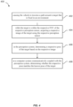
method 400 includes, at 402, causing the vehicle to traverse a path around a target that is fixed in an environment. The target has a known pose. The path is configured so that the target comes into a respective field of view (FOV) of each respective perception sensor of the one or more perception sensors along the path. - The
method 400 further includes, at 404, for each respective perception sensor of the one or more perception sensors, while the target is within the respective FOV of the respective perception sensor, acquiring a respective image of the target using the respective perception sensor; at 406, at the perception system, determining a respective pose of the target based on the respective image; and at 408, at a computer system communicatively coupled with the perception system, determining whether the respective pose matches the known pose of the target. - According to some embodiments, the
method 400 can further includes, at the computer system, upon determining that the respective pose matches the known pose of the target within a threshold, providing an indication to an operator that the respective perception sensor is correctly aligned. - According to some embodiments, the
method 400 can further includes, at the computer system, upon determining that the respective pose deviates from the known pose of the target beyond a threshold, providing an indication to an operator that the respective perception sensor is not correctly aligned. - According to some embodiments, the
method 400 can further includes, at the computer system, upon determining that, for each respective perception sensor of the one or more perception sensors, the respective pose matches the known pose of the target within a threshold, activating the perception system for navigation of the vehicle. - According to some embodiments, the
method 400 can further includes, for each respective perception sensor of the one or more perception sensors: while the target is within the respective FOV of the respective perception sensor, acquiring a sequence of images of the target using the respective perception sensor; at the perception system, determining a movement of the target with respect to the vehicle based on the sequence of images; and at the computer system, determining whether the movement of the target matches with an expected movement. - It should be appreciated that the specific steps illustrated in
FIG. 4 provide a particular method of verifying accuracy of a perception system of a vehicle according to some embodiments. Other sequences of steps may also be performed according to alternative embodiments. For example, alternative embodiments of the present invention may perform the steps outlined above in a different order. Moreover, the individual steps illustrated inFIG. 4 may include multiple sub-steps that may be performed in various sequences as appropriate to the individual step. Furthermore, additional steps may be added and some steps may be removed depending on the particular applications. One of ordinary skill in the art would recognize many variations, modifications, and alternatives. - In some embodiments, instead of driving the vehicle around a fixed target, a target can be moved around the vehicle so that it comes into the FOVs of various perception sensors. The target can be equipped with a high accuracy position solution (e.g., a GNSS) configured to measure the target's pose accurately. The pose measured by the high accuracy position solution can be used as a reference pose to verify that a perception sensor detects the target at the correct pose. The target can be carried by a person to various locations around the vehicle, or can be carried by another vehicle that is driven around the vehicle.
-
FIG. 5 illustrates a method of verifying accuracy of a perception system of avehicle 510 according to some embodiments. The perception system of thevehicle 510 can include afirst perception sensor 520 mounted on the front of thevehicle 510, and asecond perception sensor 530 mounted on the left side of thevehicle 510. For simplicity, only twoperception sensors vehicle 510 can include additional perception sensors. - To verify the accuracy of each perception sensor of the perception system, a
target 540 can be moved into the FOV of each of the perception sensors, while thevehicle 510 remains stationary. For example, thetarget 540 can be moved to afirst location 540a, which is within theFOV 522 of thefirst perception sensor 520. Thefirst perception sensor 520 can acquire a first image of thetarget 540 while thetarget 540 is at thefirst location 540a. A first pose of thetarget 540 can be determined based on the first image. Meanwhile, a position solution attached to thetarget 540 can measure a first reference pose of thetarget 540 at thefirst location 540a. If the first pose matches the first reference pose within a threshold, it can be determined that thefirst perception sensor 520 is correctly aligned. Similarly, thetarget 540 can be moved to asecond location 540c, which is within theFOV 532 of thesecond perception sensor 530. A second pose of thetarget 540 can be measured based on a second image. Meanwhile, the position solution attached to thetarget 540 can measure a second reference pose of thetarget 540 at thesecond location 540c. The second pose can be compared to a second reference pose to determine whether thesecond perception sensor 530 is correctly aligned. - In some embodiments, it can be advantages to check the accuracy of each perception sensor with the target in both far field and near field. For example, referring to
FIG. 5 , in addition to thefirst location 540a that is in the far field of thefirst perception sensor 520, the accuracy of thefirst perception sensor 520 is also verified while thetarget 540 is moved to thethird location 540b, which is in the near field of thefirst perception sensor 520. Similarly, in addition to thesecond location 540c that is in the far field of thesecond perception sensor 530, the accuracy of thesecond perception sensor 530 is also verified while thetarget 540 is moved to thefourth location 540d, which is in the near field of thesecond perception sensor 530. In some embodiments, an operator or another vehicle carrying thetarget 540 can traverse a path around thevehicle 510 designed to cover both the far field and the near field of each perception sensor of the perception system of thevehicle 510. -
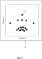
FIG. 6 shows an exemplary graphics user interface (GUI) 610 of an application for verifying the accuracy of a perception system of a vehicle according to some embodiments. TheGUI 610 displays the various locations of atarget 630. The open circles represent the positions (e.g., X and Y coordinates) of the target as measured by a positioning solution (e.g., a GNSS system) attached to the target. The solid dots represent the positions of the target as measured by a perception sensor (e.g., a radar) mounted on the vehicle. It should be noted that, although only the X and Y coordinates are shown in this example, the position of the target can include three degrees of translational freedom (e.g., latitude, longitude, and altitude). In some embodiments, the orientation of the target can also be measured, which can include three degrees of rotational freedom (e.g., roll, pitch, and yaw). - The application can compare each pair of positions (each pair of solid dot and open circle) to determine whether they match with each other. For example, a distance between a position of the target as measured by the positioning solution and a corresponding position of the target as measured by the perception sensor can be determined. If the distance is greater than a predetermined threshold (either as an absolute value or a percentage value), the application may determine that the perception sensor is not correctly aligned.
- In some embodiments, an operator may carry the target and a portable computer device to various locations around the vehicle. The computer device runs the application for verifying the accuracies of the perception sensors. The positioning solution of the target can measure the reference position of the target and send the reference position to the computer device via a wireless link. The perception system of the vehicle can measured the position of the target and send the measured position to the computer device via a wireless link. The application can then compare the measured position with the reference position.
-
FIG. 7 shows a simplified flowchart illustrating amethod 700 of verifying accuracy of a perception system of a vehicle according to some embodiments. The perception system includes one or more perception sensors mounted on the vehicle. - The
method 700 includes, at 702, for each respective perception sensor of the one or more perception sensors: moving a target to a respective location that is within a respective field of view (FOV) of the respective perception sensor; at 704, acquiring a respective image of the target using the respective perception sensor while the target is at the respective location; at 706, at the perception system, determining a respective pose of the target based on the respective image; at 708, determining a respective reference pose of the target while the target is at the respective location using a positioning solution attached to the target; and at 710, at a computer system communicatively coupled to the perception system and the positioning solution, determining whether the respective pose matches the respective reference pose. - According to some embodiments, the
method 700 can further includes, at the computer system, upon determining that the respective pose matches the respective reference pose within a threshold, providing an indication to an operator that the respective perception sensor is correctly aligned. - According to some embodiments, the
method 700 can further includes, at the computer system, upon determining that the respective pose deviates from the respective reference pose beyond a threshold, providing an indication to an operator that the respective perception sensor is not correctly aligned. - According to some embodiments, the
method 700 can further includes, at the computer system, upon determining that, for each respective perception sensor of the one or more perception sensors, the respective pose matches the respective reference pose within a threshold, causing the perception system to be activated for navigation of the vehicle. - It should be appreciated that the specific steps illustrated in
FIG. 7 provide a particular method of verifying accuracy of a perception system of a vehicle according to some embodiments. Other sequences of steps may also be performed according to alternative embodiments. For example, alternative embodiments of the present invention may perform the steps outlined above in a different order. Moreover, the individual steps illustrated inFIG. 7 may include multiple sub-steps that may be performed in various sequences as appropriate to the individual step. Furthermore, additional steps may be added and some steps may be removed depending on the particular applications. One of ordinary skill in the art would recognize many variations, modifications, and alternatives. - According to some embodiments, the methods of verifying accuracy of perception sensors described above can be applied to perception sensors that are mounted on articulated segments of a vehicle as well.
FIGS. 8A and 8B illustrate two examples.FIG. 8A shows avehicle 810 with aloader 816 attached thereto. Theloader 816 can be raised or lowered via ahydraulic arm 812. Aperception sensor 814 can be attached to theloader 816. Thus, theperception sensor 814 moves with theloader 816 as theloader 816 moves. The methods described above with reference toFIGS. 2A - 2B ,4 ,5, and7 can also be applied to verify the accuracy of theperception sensor 814. -
FIG. 8B shows avehicle 820 with a soil compactor attached thereto. The soil compactor includes aroller 826 attached to aframe 822. Aperception sensor 824 can be attached to the front of theframe 822. Other examples of vehicles with articulated segments can include a sprayer with boom arms, a harvester with a header, vehicles with a front or rear hitch, and the like. The methods described above with reference toFIGS. 2A - 2B ,4 ,5 , and7 can also be applied to these examples. - According to some embodiments, the accuracies of perception sensors can be verified by correlating the sensor data of different perception sensors.
FIGS. 9A - 9C illustrate some examples.FIG. 9A shows an example in which afirst FOV 910 of a first perception sensor is encompassed by asecond FOV 920 of a second perception sensor. Thus, if atarget 902 is positioned within thefirst FOV 910, both the first perception sensor and the second perception sensor would be able to detect it. A comparison of a first pose of thetarget 902 measured by the first perception sensor and a second pose of thetarget 902 measured by the second perception sensor can serve as a cross-check of whether the first perception sensor and/or the second perception sensor are correctly aligned. If the first pose and the second pose do not match with each other, it is likely that one or both of the first perception sensor and the second perception sensor are not correctly aligned. -
FIG. 9B shows an example in which afirst FOV 930 of a first perception sensor is partially encompassed by asecond FOV 940 of a second perception sensor. In this example, if atarget 904 is positioned within a region where thefirst FOV 930 and thesecond FOV 940 overlap, both the first perception sensor and the second perception sensor would be able to detect it. Thus, the accuracies of the first perception sensor and the second perception sensor can be cross-checked by comparing the sensor data of the two perception sensors. -
FIG. 9C shows afirst FOV 950 of a first perception sensor, asecond FOV 960 of a second perception sensor, and athird FOV 970 of a third perception sensor. As illustrated, thefirst FOV 950 partially overlaps with thesecond FOV 960, and also partially overlaps with thethird FOV 970. Thus, the accuracies of the first perception sensor and the second perception sensor can be cross-checked by placing afirst target 906 in a region where thefirst FOV 950 and thesecond FOV 960 overlap. Similarly, the accuracies of the first perception sensor and the third perception sensor can be cross-checked by placing asecond target 908 in a region where thefirst FOV 950 and thethird FOV 970 overlap. - According to some embodiments, the accuracy of a perception system of a vehicle can be verified by using targets installed on the vehicle. For example, the targets can be installed in the manufacturing plant, or can be installed when the perception system is installed. Each target is within the field of view of at least one perception sensor of the perception system. A reference pose of each target can be measured when the target is installed. For example, the reference pose can be measured using high precision laser measurement devices, GNSS sensors, or using calibrated perception sensors.
-
FIG. 10A illustrates an example of using targets installed on a vehicle to verify the accuracy of a perception system of the vehicle according to some embodiments. As illustrated, fourtargets engine hood 1010. Thetargets targets -
FIG. 10B - 10E show some exemplary types of targets that can be used.FIG. 10B shows a corner reflector that can be used as a target. The corner reflector can return a strong signal to radar sensors, allowing for accurate detection.FIG. 10C shows a ChArUco board that can be used as a target. The ChArUco board combines a chessboard with ArUco markers. The ArUco markers allow fast and versatile detection, while the chessboard allows accurate position measurements.FIG. 10D shows a cube with checkerboards that can be used as a target.FIG. 10E shows an icosahedron with deltille grids that can be used as a target. Other types of targets that allow accurate position measurements can also be used. One of ordinary skill in the art would recognize many variations, alternatives, and modifications. -
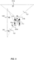
FIG. 11 illustrates another example of using targets installed on a vehicle to verify the accuracy of a perception system of the vehicle according to some embodiments. Thevehicle 1110 is a sprayer that includes twobooms vehicle 1110. Afirst perception sensor 1120 is positioned at the front of thecab 1116 of thevehicle 1110 and has aFOV 1122 directed toward the front. A second perception sensor 1130 is positioned at the left side of thevehicle 1110 and has aFOV 1132 directed toward the left. Athird perception sensor 1140 is positioned at the right side of thevehicle 1110 and has aFOV 1142 directed toward the right. Afirst target 1150 and asecond target 1160 can be installed at the two front corners of the engine hood 1118, so that they are in theFOV 1122 of thefirst perception sensor 1120. Athird target 1170 can be installed on theleft boom 1114, so that it is in theFOV 1132 of the second perception sensor 1130. Afourth target 1180 can be installed on theright boom 1112, so that it is in theFOV 1142 of thethird perception sensor 1140. Thefirst perception sensor 1120 can measure a pose of each thefirst target 1150 and thesecond target 1160, and compare the measured pose with a first reference pose and a second reference pose, respectively. The second perception sensor 1130 can measure a pose of thethird target 1170, and compare the measured pose with a third reference pose. Thethird perception sensor 1140 can measure a pose of thefourth target 1180, and compare the measured pose with a fourth reference pose. - According to some embodiments, prior to operating a vehicle, sensor data from various perception sensors can be queried to verify that each perception sensor correctly detects a respective target installed on the vehicle. If one or more perception sensors are not correctly aligned, the perception system of the vehicle may not be activated for the navigation of the vehicle, and an operator can be alerted to the problem. In some embodiments, sensor data from various perception sensors can be continuously queried during the operation of the vehicle, to verify that each perception sensor correctly detects a respective target installed on the vehicle. Thus, a sensor misalignment (e.g., caused by hitting a tree branch) can be detected as soon as it happens.
-
FIG. 12 shows an exemplary block diagram of a perceptionsystem test system 1210 that can perform the methods of verifying accuracy of a perception system of a vehicle described herein according to some embodiments. The perceptionsystem test system 1210 can include a computer processor and adata storage device 1212. The perceptionsystem test system 1210 can also include auser interface 1214, and optionally awireless communication device 1216. The perceptionsystem test system 1210 can be communicatively coupled to theperception system 1210 of the vehicle. Theperception system 1220 of the vehicle can include one ormore perception sensors 1222 mounted on the vehicle, and a computer processor and adata storage device 1224. Theperception system 1220 can include an optionalwireless communication device 1226. In some embodiments, the perceptionsystem test system 1210 can be communicatively coupled to theperception system 1220 via thewireless communication devices system test system 1210 can be part of theperception system 1220. - The perception
system test system 1210 can also be communicatively coupled to apositioning solution 1230 attached to a target. In some embodiments, thepositioning solution 1230 can include one ormore antennas 1231 and one ormore GNSS receivers 1232 coupled to the one ormore antennas 1231. The one ormore GNSS receivers 1232 may be configured to determine a position of the target based on the satellite signals received from GNSS satellites. The one ormore GNSS receivers 1232 may also be configured to determine an orientation of the target (e.g., using two GNSS receivers spaced apart from each other). In some embodiments, thepositioning solution 1230 can include aposition correction system 1234. Theposition correction system 1234 can include anantenna 1235 and areceiver 1236 for receiving correction data from a reference station or a network of reference stations. For example, theposition correction system 1234 may include a differential global positioning system (DGPS). The correction data may be used by theGNSS receivers 1236 to determine a more precise position of the target (e.g., to millimeter or sub-millimeter accuracies). In some embodiments, thepositioning solution 1230 can includeadditional sensors 1233, such as inertial measurement units (IMUs) and the like. Thepositioning solution 1230 can include awireless communication device 1238. In some embodiments, the perceptionsystem test system 1210 can be communicatively coupled to thepositioning solution 1230 via thewireless communication devices perception system 1220 can also be communicatively coupled to a positioning solution (similar to the positioning solution 1230) that is attached to the vehicle and configured to determine the position of the vehicle. Theperception system 1220 can be configured to estimate the location of the target with respect to the vehicle coordinate system based on the data of the perception sensors and the GNSS data, as well as other sensor data (e.g., IMU data and the like). - It is also understood that the examples and embodiments described herein are for illustrative purposes only and that various modifications or changes in light thereof will be suggested to persons skilled in the art and are to be included within the spirit and purview of this application and scope of the appended claims.
- An itemized list of examples is presented below.
- 1. A method of verifying accuracy of a perception system of a vehicle, the perception system including one or more perception sensors mounted on the vehicle, the method comprising:
- causing the vehicle to traverse a path around a target that is fixed in an environment, the target having a known pose, the path being configured so that the target comes into a respective field of view (FOV) of each respective perception sensor of the one or more perception sensors along the path;
- for each respective perception sensor of the one or more perception sensors:
- while the target is within the respective FOV of the respective perception sensor, acquiring a respective image of the target using the respective perception sensor;
- at the perception system, determining a respective pose of the target based on the respective image; and
- at a computer system communicatively coupled with the perception system, determining whether the respective pose matches the known pose of the target.
- 2. The method of
item 1 further comprising:
at the computer system, upon determining that the respective pose matches the known pose of the target within a threshold, providing an indication to an operator that the respective perception sensor is correctly aligned. - 3. The method of
item 1 further comprising:
at the computer system, upon determining that the respective pose deviates from the known pose of the target beyond a threshold, providing an indication to an operator that the respective perception sensor is not correctly aligned. - 4. The method of
item 1 further comprising:
at the computer system, upon determining that, for each respective perception sensor of the one or more perception sensors, the respective pose matches the known pose of the target within a threshold, activating the perception system for navigation of the vehicle. - 5. The method of
item 1 wherein the respective pose comprises a respective position and a respective orientation of the target, and the known pose comprises a known position and a known orientation of the target. - 6. The method of item 5 wherein the respective position of the target includes three degrees of freedom, the known position of the target includes three degrees of freedom, the respective orientation of the target includes three degrees of freedom, and the known orientation of the target includes three degrees of freedom.
- 7. The method of item 5 wherein the known position and the known orientation of the target are determined by one or more global navigation satellite systems (GNSS) devices.
- 8. The method of
item 1 wherein the one or more perception sensors comprise one or more radar sensors, one or more LiDAR sensors, one or more cameras, or a combination thereof. - 9. The method of item 8 wherein the respective image of the target acquired by the respective perception sensor comprises a three-dimensional image or a two-dimensional image.
- 10. The method of
item 1 further comprising, for each respective perception sensor of the one or more perception sensors:- while the target is within the respective FOV of the respective perception sensor, acquiring a sequence of images of the target using the respective perception sensor;
- at the perception system, determining a movement of the target with respect to the vehicle based on the sequence of images; and
- at the computer system, determining whether the movement of the target matches with an expected movement.
- 11. The method of
item 1 wherein the one or more perception sensors comprise at least a first perception sensor and a second perception sensor, and the target is within both a first FOV of the first perception sensor and a second FOV of the second perception sensor simultaneously along a portion of the path, the method further comprising, while the vehicle is along the portion of the path:- acquiring a first image of the target using the first perception sensor;
- acquiring a second image of the target using the second perception sensor concurrently with the acquiring of the first image by the first perception sensor;
- at the perception system:
- determining a first pose of the target based on the first image; and
- determining a second pose of the target based on the second image; and
- at the computer system, determining whether the first pose matches the second pose.
- 12. A method of verifying accuracy of a perception system of a vehicle, the perception system including one or more perception sensors mounted on the vehicle, the method comprising, for each respective perception sensor of the one or more perception sensors:
- moving a target to a respective location that is within a respective field of view (FOV) of the respective perception sensor;
- acquiring a respective image of the target using the respective perception sensor while the target is at the respective location;
- at the perception system, determining a respective pose of the target based on the respective image;
- determining a respective reference pose of the target while the target is at the respective location using a positioning solution attached to the target; and
- at a computer system communicatively coupled to the perception system and the positioning solution, determining whether the respective pose matches the respective reference pose.
- 13. The method of item 12 further comprising:
at the computer system, upon determining that the respective pose matches the respective reference pose within a threshold, providing an indication to an operator that the respective perception sensor is correctly aligned. - 14. The method of item 12 further comprising:
at the computer system, upon determining that the respective pose deviates from the respective reference pose beyond a threshold, providing an indication to an operator that the respective perception sensor is not correctly aligned. - 15. The method of item 12 further comprising:
at the computer system, upon determining that, for each respective perception sensor of the one or more perception sensors, the respective pose matches the respective reference pose within a threshold, causing the perception system to be activated for navigation of the vehicle. - 16. The method of item 12 wherein the positioning solution comprises one or more global navigation satellite systems (GNSS) devices attached to the target.
- 17. The method of item 12 wherein the one or more perception sensors comprise one or more radar sensors, one or more LiDAR sensors, one or more cameras, or a combination thereof.
- 18. The method of item 12 wherein at least one of the one or more perception sensors is mounted on an articulated segment of the vehicle.
- 19. The method of item 12 wherein the one or more perception sensors comprise at least a first perception sensor with a first FOV and a second perception sensor with a second FOV, and the second FOV at least partially overlaps with the first FOV, the method further comprising:
- moving the target to a first location that is within both the first FOV and the second FOV;
- acquiring a first image of the target using the first perception sensor;
- acquiring a second image of the target using the second perception sensor;
- at the perception system:
- determining a first pose of the target based on the first image; and
- determining a second pose of the target based on the second image; and
- at the computer system, determining whether the first pose matches the second pose.
- 20. The method of item 12 wherein the one or more perception sensors includes a first perception sensor with a first FOV, the vehicle includes a first target mounted at a first location on the vehicle, the first location being within the first FOV of the first perception sensor, and the first target has a known pose at the first location, the method further comprising:
- acquiring a first image of the first target using the first perception sensor;
- at the perception system, determining a first pose of the first target based on the first image; and
- at the computer system, determining whether the first pose matches the known pose.
Claims (15)
- A method of verifying accuracy of a perception system of a vehicle, the perception system including one or more perception sensors mounted on the vehicle, the method comprising:causing the vehicle to traverse a path around a target that is fixed in an environment, the target having a known pose, the path being configured so that the target comes into a respective field of view, FOV, of each respective perception sensor of the one or more perception sensors along the path;for each respective perception sensor of the one or more perception sensors:while the target is within the respective FOV of the respective perception sensor, acquiring a respective image of the target using the respective perception sensor;at the perception system, determining a respective pose of the target based on the respective image; andat a computer system communicatively coupled with the perception system, determining whether the respective pose matches the known pose of the target.
- The method of claim 1 further comprising:
at the computer system, upon determining that the respective pose matches the known pose of the target within a threshold, providing an indication to an operator that the respective perception sensor is correctly aligned. - The method of claim 1 further comprising:
at the computer system, upon determining that the respective pose deviates from the known pose of the target beyond a threshold, providing an indication to an operator that the respective perception sensor is not correctly aligned. - The method of claim 1 further comprising:
at the computer system, upon determining that, for each respective perception sensor of the one or more perception sensors, the respective pose matches the known pose of the target within a threshold, activating the perception system for navigation of the vehicle. - The method of any one of the preceding claims wherein the respective pose comprises a respective position and a respective orientation of the target, and the known pose comprises a known position and a known orientation of the target.
- The method of any one of the preceding claims further comprising, for each respective perception sensor of the one or more perception sensors:while the target is within the respective FOV of the respective perception sensor, acquiring a sequence of images of the target using the respective perception sensor;at the perception system, determining a movement of the target with respect to the vehicle based on the sequence of images; andat the computer system, determining whether the movement of the target matches with an expected movement.
- The method of any one of the preceding claims wherein the one or more perception sensors comprise at least a first perception sensor and a second perception sensor, and the target is within both a first FOV of the first perception sensor and a second FOV of the second perception sensor simultaneously along a portion of the path, the method further comprising, while the vehicle is along the portion of the path:acquiring a first image of the target using the first perception sensor;acquiring a second image of the target using the second perception sensor concurrently with the acquiring of the first image by the first perception sensor;at the perception system:determining a first pose of the target based on the first image; anddetermining a second pose of the target based on the second image; andat the computer system, determining whether the first pose matches the second pose.
- A method of verifying accuracy of a perception system of a vehicle, the perception system including one or more perception sensors mounted on the vehicle, the method comprising, for each respective perception sensor of the one or more perception sensors:moving a target to a respective location that is within a respective field of view, FOV, of the respective perception sensor;acquiring a respective image of the target using the respective perception sensor while the target is at the respective location;at the perception system, determining a respective pose of the target based on the respective image;determining a respective reference pose of the target while the target is at the respective location using a positioning solution attached to the target; andat a computer system communicatively coupled to the perception system and the positioning solution, determining whether the respective pose matches the respective reference pose.
- The method of claim 8 further comprising:
at the computer system, upon determining that the respective pose matches the respective reference pose within a threshold, providing an indication to an operator that the respective perception sensor is correctly aligned. - The method of claim 8 further comprising:
at the computer system, upon determining that the respective pose deviates from the respective reference pose beyond a threshold, providing an indication to an operator that the respective perception sensor is not correctly aligned. - The method of claim 8 further comprising:
at the computer system, upon determining that, for each respective perception sensor of the one or more perception sensors, the respective pose matches the respective reference pose within a threshold, causing the perception system to be activated for navigation of the vehicle. - The method of any one of claims 8-11 wherein the positioning solution comprises one or more global navigation satellite systems, GNSS, devices attached to the target.
- The method of any one of claims 8-12 wherein the one or more perception sensors comprise one or more radar sensors, one or more LiDAR sensors, one or more cameras, or a combination thereof.
- The method of any one of claims 8-13 wherein the one or more perception sensors comprise at least a first perception sensor with a first FOV and a second perception sensor with a second FOV, and the second FOV at least partially overlaps with the first FOV, the method further comprising:moving the target to a first location that is within both the first FOV and the second FOV;acquiring a first image of the target using the first perception sensor;acquiring a second image of the target using the second perception sensor;at the perception system:determining a first pose of the target based on the first image; anddetermining a second pose of the target based on the second image; andat the computer system, determining whether the first pose matches the second pose.
- The method of any one of claims 8-13 wherein the one or more perception sensors includes a first perception sensor with a first FOV, the vehicle includes a first target mounted at a first location on the vehicle, the first location being within the first FOV of the first perception sensor, and the first target has a known pose at the first location, the method further comprising:acquiring a first image of the first target using the first perception sensor;at the perception system, determining a first pose of the first target based on the first image; andat the computer system, determining whether the first pose matches the known pose.
Applications Claiming Priority (1)
| Application Number | Priority Date | Filing Date | Title |
|---|---|---|---|
| US17/473,051 US12319310B2 (en) | 2021-09-13 | 2021-09-13 | Accuracy verification of a perception system of a vehicle |
Publications (2)
| Publication Number | Publication Date |
|---|---|
| EP4148674A1 true EP4148674A1 (en) | 2023-03-15 |
| EP4148674B1 EP4148674B1 (en) | 2025-12-10 |
Family
ID=83546831
Family Applications (1)
| Application Number | Title | Priority Date | Filing Date |
|---|---|---|---|
| EP22194897.9A Active EP4148674B1 (en) | 2021-09-13 | 2022-09-09 | Accuracy verification of a perception system of a vehicle |
Country Status (2)
| Country | Link |
|---|---|
| US (2) | US12319310B2 (en) |
| EP (1) | EP4148674B1 (en) |
Citations (3)
| Publication number | Priority date | Publication date | Assignee | Title |
|---|---|---|---|---|
| US20180307238A1 (en) * | 2017-04-20 | 2018-10-25 | GM Global Technology Operations LLC | Calibration validation for autonomous vehicle operations |
| US20200406904A1 (en) * | 2019-06-28 | 2020-12-31 | Gm Cruise Holdings Llc | Wireless vehicle control of vehicle sensor calibration environment |
| US20210146942A1 (en) * | 2018-07-06 | 2021-05-20 | Brain Corporation | Systems, methods and apparatuses for calibrating sensors mounted on a device |
Family Cites Families (1)
| Publication number | Priority date | Publication date | Assignee | Title |
|---|---|---|---|---|
| US11199614B1 (en) * | 2020-07-08 | 2021-12-14 | Beijing Voyager Technology Co., Ltd | Lidar and image calibration for autonomous vehicles |
-
2021
- 2021-09-13 US US17/473,051 patent/US12319310B2/en active Active
-
2022
- 2022-09-09 EP EP22194897.9A patent/EP4148674B1/en active Active
-
2025
- 2025-04-29 US US19/193,017 patent/US20250269872A1/en active Pending
Patent Citations (3)
| Publication number | Priority date | Publication date | Assignee | Title |
|---|---|---|---|---|
| US20180307238A1 (en) * | 2017-04-20 | 2018-10-25 | GM Global Technology Operations LLC | Calibration validation for autonomous vehicle operations |
| US20210146942A1 (en) * | 2018-07-06 | 2021-05-20 | Brain Corporation | Systems, methods and apparatuses for calibrating sensors mounted on a device |
| US20200406904A1 (en) * | 2019-06-28 | 2020-12-31 | Gm Cruise Holdings Llc | Wireless vehicle control of vehicle sensor calibration environment |
Also Published As
| Publication number | Publication date |
|---|---|
| US20250269872A1 (en) | 2025-08-28 |
| US12319310B2 (en) | 2025-06-03 |
| US20230084479A1 (en) | 2023-03-16 |
| EP4148674B1 (en) | 2025-12-10 |
Similar Documents
| Publication | Publication Date | Title |
|---|---|---|
| US12554262B2 (en) | 3-D image system for vehicle control | |
| JP7154362B2 (en) | work vehicle | |
| CN110174093B (en) | Positioning method, device, equipment and computer readable storage medium | |
| US10989560B2 (en) | Map data correcting method and device | |
| US20230264702A1 (en) | Integrated fiducial marker for simultaneously calibrating sensors of different types | |
| EP3913328B1 (en) | Vehicle positioning system and method, and vehicle | |
| US20220382292A1 (en) | Route Determination Method, Route Determination System, And Route Determination Program | |
| KR101880185B1 (en) | Electronic apparatus for estimating pose of moving object and method thereof | |
| EP3168705A1 (en) | Domestic robotic system | |
| US12475593B2 (en) | Positioning system and moving body for measuring position of moving body using image capturing apparatus | |
| US20180372841A1 (en) | Sensor Calibration System | |
| US11609340B2 (en) | System and method for GPS based automatic initiation of sensor calibration | |
| KR102006291B1 (en) | Method for estimating pose of moving object of electronic apparatus | |
| US11635313B2 (en) | System and method for simultaneously multiple sensor calibration and transformation matrix computation | |
| US20220333355A1 (en) | Control system of construction machinery and method of providing working guide line | |
| KR102373825B1 (en) | Vehicle navigaton switching device for golf course self-driving cars | |
| JP2018021865A (en) | Mobile body, method for controlling mobile body, program for controlling mobile body, control system, and information processor | |
| WO2025109371A1 (en) | Ego vehicle location determination using sparse high-accuracy object locations | |
| EP4148674A1 (en) | Accuracy verification of a perception system of a vehicle | |
| JP7771387B2 (en) | Sensing system, agricultural machine, and sensing device | |
| EP4019897B1 (en) | Autonomous travel system | |
| Trusheim et al. | Cooperative localisation using image sensors in a dynamic traffic scenario | |
| US20220018950A1 (en) | Indoor device localization | |
| NL2035443B1 (en) | System and method for monitoring a dyke | |
| Cheng et al. | Autonomous Navigation System for Agricultural Vehicles Using Machine Vision Recognition and Localization of Panoramic Landmarks |
Legal Events
| Date | Code | Title | Description |
|---|---|---|---|
| PUAI | Public reference made under article 153(3) epc to a published international application that has entered the european phase |
Free format text: ORIGINAL CODE: 0009012 |
|
| STAA | Information on the status of an ep patent application or granted ep patent |
Free format text: STATUS: THE APPLICATION HAS BEEN PUBLISHED |
|
| AK | Designated contracting states |
Kind code of ref document: A1 Designated state(s): AL AT BE BG CH CY CZ DE DK EE ES FI FR GB GR HR HU IE IS IT LI LT LU LV MC MK MT NL NO PL PT RO RS SE SI SK SM TR |
|
| STAA | Information on the status of an ep patent application or granted ep patent |
Free format text: STATUS: REQUEST FOR EXAMINATION WAS MADE |
|
| 17P | Request for examination filed |
Effective date: 20230907 |
|
| RBV | Designated contracting states (corrected) |
Designated state(s): AL AT BE BG CH CY CZ DE DK EE ES FI FR GB GR HR HU IE IS IT LI LT LU LV MC MK MT NL NO PL PT RO RS SE SI SK SM TR |
|
| GRAP | Despatch of communication of intention to grant a patent |
Free format text: ORIGINAL CODE: EPIDOSNIGR1 |
|
| STAA | Information on the status of an ep patent application or granted ep patent |
Free format text: STATUS: GRANT OF PATENT IS INTENDED |
|
| INTG | Intention to grant announced |
Effective date: 20250724 |
|
| GRAS | Grant fee paid |
Free format text: ORIGINAL CODE: EPIDOSNIGR3 |
|
| GRAA | (expected) grant |
Free format text: ORIGINAL CODE: 0009210 |
|
| STAA | Information on the status of an ep patent application or granted ep patent |
Free format text: STATUS: THE PATENT HAS BEEN GRANTED |
|
| AK | Designated contracting states |
Kind code of ref document: B1 Designated state(s): AL AT BE BG CH CY CZ DE DK EE ES FI FR GB GR HR HU IE IS IT LI LT LU LV MC MK MT NL NO PL PT RO RS SE SI SK SM TR |
|
| RAP3 | Party data changed (applicant data changed or rights of an application transferred) |
Owner name: TRIMBLE INC. |
|
| REG | Reference to a national code |
Ref country code: CH Ref legal event code: F10 Free format text: ST27 STATUS EVENT CODE: U-0-0-F10-F00 (AS PROVIDED BY THE NATIONAL OFFICE) Effective date: 20251210 Ref country code: GB Ref legal event code: FG4D |
|
| REG | Reference to a national code |
Ref country code: DE Ref legal event code: R096 Ref document number: 602022026471 Country of ref document: DE |
|
| REG | Reference to a national code |
Ref country code: IE Ref legal event code: FG4D |
|
| PG25 | Lapsed in a contracting state [announced via postgrant information from national office to epo] |
Ref country code: ES Free format text: LAPSE BECAUSE OF FAILURE TO SUBMIT A TRANSLATION OF THE DESCRIPTION OR TO PAY THE FEE WITHIN THE PRESCRIBED TIME-LIMIT Effective date: 20251210 |
|
| REG | Reference to a national code |
Ref country code: LT Ref legal event code: MG9D |
|
| PG25 | Lapsed in a contracting state [announced via postgrant information from national office to epo] |
Ref country code: NO Free format text: LAPSE BECAUSE OF FAILURE TO SUBMIT A TRANSLATION OF THE DESCRIPTION OR TO PAY THE FEE WITHIN THE PRESCRIBED TIME-LIMIT Effective date: 20260310 |
|
| PG25 | Lapsed in a contracting state [announced via postgrant information from national office to epo] |
Ref country code: FI Free format text: LAPSE BECAUSE OF FAILURE TO SUBMIT A TRANSLATION OF THE DESCRIPTION OR TO PAY THE FEE WITHIN THE PRESCRIBED TIME-LIMIT Effective date: 20251210 Ref country code: HR Free format text: LAPSE BECAUSE OF FAILURE TO SUBMIT A TRANSLATION OF THE DESCRIPTION OR TO PAY THE FEE WITHIN THE PRESCRIBED TIME-LIMIT Effective date: 20251210 |
|
| REG | Reference to a national code |
Ref country code: NL Ref legal event code: MP Effective date: 20251210 |
|
| PG25 | Lapsed in a contracting state [announced via postgrant information from national office to epo] |
Ref country code: RS Free format text: LAPSE BECAUSE OF FAILURE TO SUBMIT A TRANSLATION OF THE DESCRIPTION OR TO PAY THE FEE WITHIN THE PRESCRIBED TIME-LIMIT Effective date: 20260310 |
|
| PG25 | Lapsed in a contracting state [announced via postgrant information from national office to epo] |
Ref country code: LV Free format text: LAPSE BECAUSE OF FAILURE TO SUBMIT A TRANSLATION OF THE DESCRIPTION OR TO PAY THE FEE WITHIN THE PRESCRIBED TIME-LIMIT Effective date: 20251210 |