EP4148521A1 - Autonomous instrument management - Google Patents
Autonomous instrument management Download PDFInfo
- Publication number
- EP4148521A1 EP4148521A1 EP22191592.9A EP22191592A EP4148521A1 EP 4148521 A1 EP4148521 A1 EP 4148521A1 EP 22191592 A EP22191592 A EP 22191592A EP 4148521 A1 EP4148521 A1 EP 4148521A1
- Authority
- EP
- European Patent Office
- Prior art keywords
- cause
- data
- error condition
- module
- measurement data
- Prior art date
- Legal status (The legal status is an assumption and is not a legal conclusion. Google has not performed a legal analysis and makes no representation as to the accuracy of the status listed.)
- Granted
Links
Images


Classifications
-
- G—PHYSICS
- G05—CONTROLLING; REGULATING
- G05B—CONTROL OR REGULATING SYSTEMS IN GENERAL; FUNCTIONAL ELEMENTS OF SUCH SYSTEMS; MONITORING OR TESTING ARRANGEMENTS FOR SUCH SYSTEMS OR ELEMENTS
- G05B19/00—Program-control systems
- G05B19/02—Program-control systems electric
- G05B19/418—Total factory control, i.e. centrally controlling a plurality of machines, e.g. direct or distributed numerical control [DNC], flexible manufacturing systems [FMS], integrated manufacturing systems [IMS] or computer integrated manufacturing [CIM]
- G05B19/41865—Total factory control, i.e. centrally controlling a plurality of machines, e.g. direct or distributed numerical control [DNC], flexible manufacturing systems [FMS], integrated manufacturing systems [IMS] or computer integrated manufacturing [CIM] characterised by job scheduling, process planning, material flow
-
- G—PHYSICS
- G05—CONTROLLING; REGULATING
- G05B—CONTROL OR REGULATING SYSTEMS IN GENERAL; FUNCTIONAL ELEMENTS OF SUCH SYSTEMS; MONITORING OR TESTING ARRANGEMENTS FOR SUCH SYSTEMS OR ELEMENTS
- G05B23/00—Testing or monitoring of control systems or parts thereof
- G05B23/02—Electric testing or monitoring
- G05B23/0205—Electric testing or monitoring by means of a monitoring system capable of detecting and responding to faults
- G05B23/0259—Electric testing or monitoring by means of a monitoring system capable of detecting and responding to faults characterized by the response to fault detection
- G05B23/0275—Fault isolation and identification, e.g. classify fault; estimate cause or root of failure
- G05B23/0278—Qualitative, e.g. if-then rules; Fuzzy logic; Lookup tables; Symptomatic search; FMEA
-
- G—PHYSICS
- G06—COMPUTING OR CALCULATING; COUNTING
- G06F—ELECTRIC DIGITAL DATA PROCESSING
- G06F11/00—Error detection; Error correction; Monitoring
- G06F11/07—Responding to the occurrence of a fault, e.g. fault tolerance
- G06F11/0703—Error or fault processing not based on redundancy, i.e. by taking additional measures to deal with the error or fault not making use of redundancy in operation, in hardware, or in data representation
- G06F11/0751—Error or fault detection not based on redundancy
- G06F11/0754—Error or fault detection not based on redundancy by exceeding limits
-
- G—PHYSICS
- G06—COMPUTING OR CALCULATING; COUNTING
- G06F—ELECTRIC DIGITAL DATA PROCESSING
- G06F11/00—Error detection; Error correction; Monitoring
- G06F11/07—Responding to the occurrence of a fault, e.g. fault tolerance
- G06F11/0703—Error or fault processing not based on redundancy, i.e. by taking additional measures to deal with the error or fault not making use of redundancy in operation, in hardware, or in data representation
- G06F11/079—Root cause analysis, i.e. error or fault diagnosis
-
- G—PHYSICS
- G05—CONTROLLING; REGULATING
- G05B—CONTROL OR REGULATING SYSTEMS IN GENERAL; FUNCTIONAL ELEMENTS OF SUCH SYSTEMS; MONITORING OR TESTING ARRANGEMENTS FOR SUCH SYSTEMS OR ELEMENTS
- G05B2219/00—Program-control systems
- G05B2219/30—Nc systems
- G05B2219/34—Director, elements to supervisory
- G05B2219/34242—For measurement only
-
- G—PHYSICS
- G06—COMPUTING OR CALCULATING; COUNTING
- G06F—ELECTRIC DIGITAL DATA PROCESSING
- G06F11/00—Error detection; Error correction; Monitoring
- G06F11/07—Responding to the occurrence of a fault, e.g. fault tolerance
- G06F11/0703—Error or fault processing not based on redundancy, i.e. by taking additional measures to deal with the error or fault not making use of redundancy in operation, in hardware, or in data representation
- G06F11/0706—Error or fault processing not based on redundancy, i.e. by taking additional measures to deal with the error or fault not making use of redundancy in operation, in hardware, or in data representation the processing taking place on a specific hardware platform or in a specific software environment
- G06F11/0709—Error or fault processing not based on redundancy, i.e. by taking additional measures to deal with the error or fault not making use of redundancy in operation, in hardware, or in data representation the processing taking place on a specific hardware platform or in a specific software environment in a distributed system consisting of a plurality of standalone computer nodes, e.g. clusters, client-server systems
-
- G—PHYSICS
- G06—COMPUTING OR CALCULATING; COUNTING
- G06F—ELECTRIC DIGITAL DATA PROCESSING
- G06F11/00—Error detection; Error correction; Monitoring
- G06F11/07—Responding to the occurrence of a fault, e.g. fault tolerance
- G06F11/0703—Error or fault processing not based on redundancy, i.e. by taking additional measures to deal with the error or fault not making use of redundancy in operation, in hardware, or in data representation
- G06F11/0793—Remedial or corrective actions
-
- G—PHYSICS
- G06—COMPUTING OR CALCULATING; COUNTING
- G06F—ELECTRIC DIGITAL DATA PROCESSING
- G06F2201/00—Indexing scheme relating to error detection, to error correction, and to monitoring
- G06F2201/805—Real-time
-
- G—PHYSICS
- G06—COMPUTING OR CALCULATING; COUNTING
- G06F—ELECTRIC DIGITAL DATA PROCESSING
- G06F2201/00—Indexing scheme relating to error detection, to error correction, and to monitoring
- G06F2201/81—Threshold
Definitions
- Autonomous instrument management is used by a variety of industries to achieve a production level of consistency, economy, and safety which could not be achieved purely by human manual control. It is implemented widely in industries such as oil refining, pulp and paper manufacturing, chemical processing and power generating plants.
- an instrument management system can sit in proximity to a plant and can manipulate a valve, start a motor, alter the settings of a device or sensor, or run a chiller or mixing unit as needed.
- Instrument management systems can also diagnose faults to prevent an unmanaged problem.
- An instrument management system can monitor a number of measuring devices to ensure their values are within an expected range for the device whose operation it is taking measurements of, for example.
- the measuring devices can obtain real-time values during operation of the process it is controlling. This can include, for example, temperature readings, pressure readings, gas flow readings, and the like.
- Instrument management systems can also report a status of a device or process it controls. This can include, for example, that a device is: out of fiscal reading; out of range; has a device error; and others.
- Determining the root cause of an error in a device is a complex and time-consuming task that requires deep knowledge and experience. Highly-skilled and trained technicians are usually required and are typically expensive and in short supply. What is needed is an instrument management that is capable of handling some portion of the faults in its controlled system without human intervention. This will not only make the system more cost-effective, but also reduce the downtime and increase the reliability of the entire system.
- One embodiment is an instrument management device, which includes a monitor module for a first device, wherein the first device is configured to obtain measurement data from a second device, to compare the measurement data to a reference value, and to send a signal when the measurement data in comparison to the reference indicates an error condition, a recommendation module to receive the signal from the monitoring module, to analyze the signal, and to generate one or more recommendations associated with the error condition by using a cause and effect module, the cause and effect module comprising a data structure having at least one row and at least one column, the recommendation module accessing a data item from one of the rows or one of the columns of the cause and effect module, a ticket generation module to receive the one or more recommendations including the data item, to obtain a resolution of the error condition by altering a state of the second device, and to generate a data package associated with the resolution of the error condition, and a machine learning module configured to use the package to determine whether to update the cause and effect module, and if so altering the data item in one of the rows or one of the columns.
- Another embodiment is a system, which includes a monitoring system for a first device, wherein the first device is configured to obtain measurement data from a second device, to compare the measurement data to a reference value, and to send a signal when the measurement data in comparison to the reference indicates an error condition, a recommendation system to receive the signal from the monitoring system, to analyze the signal, and to generate one or more recommendations associated with the error condition by using a cause and effect table, the cause and effect table comprising a data structure having at least one row and at least one column, the recommendation system accessing a data item from one of the rows or one of the columns of the cause and effect table, a ticket generation system to receive the one or more recommendations including the data item, to obtain a resolution of the error condition by altering a state of the second device, and to generate a data package associated with the resolution of the error condition, and a machine learning system configured to use the package to determine whether to update the cause and effect table, and if so altering the data item in one of the rows or one of the columns.
- a method comprises obtaining measurement data from a device, comparing the measurement data to a reference value, receiving a signal when the measurement data in comparison to the reference value indicates an error condition, using a cause and effect table to generate one or more recommendations associated with the error condition by, the cause and effect table comprising a data structure having at least one row and at least one column, the step of using further comprising accessing a data item from one of the rows or one of the columns of the cause and effect table, obtaining a resolution of the error condition by altering a state of the device, generating a data package associated with the resolution of the error condition, and using the package to determine whether to update the cause and effect table, and if so altering the data item in one of the rows or one of the columns.
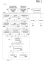
- FIG 1 illustrates an example autonomous instrument management system 100 according to this disclosure.
- the system 100 includes various components that facilitate production or processing of at least one product or other material.
- the system 100 is used here to facilitate control over components in one or multiple plants, shown in FIG 1 as 101a, 101b, and 101n (referred to hereinafter as 101a-101n).
- Each plant 101a-101n represents one or more processing facilities (or one or more portions thereof), such as one or more manufacturing facilities for producing at least one product or other material.
- each plant 101a-101n may implement one or more processes and can individually or collectively be referred to as a process system.
- a process system generally represents any system or portion thereof configured to process one or more products or other materials in some manner.
- Level 0 may include one or more sensors 102a and one or more actuators 102b.
- the sensors 102a and actuators 102b represent components in a process system that may perform any of a wide variety of functions.
- the sensors 102a could measure a wide variety of characteristics in the process system, such as temperature, pressure, volume, or flow rate and could include such instruments as ultrasonic flow meters, turbines, orifices, Coriolis, gas chromatographs, P&T transmitters, flow computers, and the like.
- the actuators 102b could alter a wide variety of characteristics in the process system.
- the sensors 102a and actuators 102b could represent any other or additional components in any suitable process system.
- Each of the sensors 102a includes any suitable structure for measuring one or more characteristics in a process system.
- Each of the actuators 102b includes any suitable structure for operating on or affecting one or more conditions in a process system.
- the sensors and actuators may be generally referred to as field devices.
- At least one network 104 is coupled to the sensors 102a and actuators 102b.
- the network 104 facilitates interaction with the sensors 102a and actuators 102b.
- the network 104 could transport measurement data from the sensors 102a and provide control signals to the actuators 102b.
- the network 104 could represent any suitable network or combination of networks.
- the network 104 could represent an Ethernet network, an electrical signal network (such as a HART or FOUNDATION FIELDBUS network), a pneumatic control signal network, or any other or additional type(s) of network(s).
- Level 1 may include one or more controllers 106, which are coupled to the network 104.
- each controller 106 may use the measurements from one or more sensors 102a to control the operation of one or more actuators 102b.
- a controller 106 could receive measurement data from one or more sensors 102a and use the measurement data to generate control signals for one or more actuators 102b.
- Multiple controllers 106 could also operate in redundant configurations, such as when one controller 106 operates as a primary controller while another controller 106 operates as a backup controller (which synchronizes with the primary controller and can take over for the primary controller in the event of a fault with the primary controller).
- Each controller 106 includes any suitable structure for interacting with one or more sensors 102a and controlling one or more actuators 102b.
- Each controller 106 could, for example, represent a multivariable controller, such as a Robust Multivariable Predictive Control Technology (RMPCT) controller or other type of controller implementing model predictive control (MPC) or other advanced predictive control (APC).
- RPCT Robust Multivariable Predictive Control Technology
- MPC model predictive control
- API advanced predictive control
- each controller 106 could represent a computing device running a real-time operating system.
- the networks 108 are coupled to the controllers 106.
- the networks 108 facilitate interaction with the controllers 106, such as by transporting data to and from the controllers 106.
- the networks 108 could represent any suitable networks or combination of networks.
- the networks 108 could represent a pair of Ethernet networks or a redundant pair of Ethernet networks, such as a FAULT TOLERANT ETHERNET (FTE) network from HONEYWELL INTERNATIONAL INC.
- FTE FAULT TOLERANT ETHERNET
- At least one switch/firewall 110 couples the networks 108 to two networks 112.
- the switch/firewall 110 may transport traffic from one network to another.
- the switch/firewall 110 may also block traffic on one network from reaching another network.
- the switch/firewall 110 includes any suitable structure for providing communication between networks, such as a HONEYWELL CONTROL FIREWALL (CF9) device.
- the networks 112 could represent any suitable networks, such as a pair of Ethernet networks or an FTE network.
- Level 2 may include one or more machine-level controllers 114 coupled to the networks 112.
- the machine-level controllers 114 perform various functions to support the operation and control of the controllers 106, sensors 102a, and actuators 102b, which could be associated with a particular piece of industrial equipment (such as a boiler or other machine).
- the machine-level controllers 114 could log information collected or generated by the controllers 106, such as measurement data from the sensors 102a or control signals for the actuators 102b.
- the machine-level controllers 114 could also execute applications that control the operation of the controllers 106, thereby controlling the operation of the actuators 102b.
- the machine-level controllers 114 could provide secure access to the controllers 106.
- Each of the machine-level controllers 114 includes any suitable structure for providing access to, control of, or operations related to a machine or other individual piece of equipment.
- Each of the machine-level controllers 114 could, for example, represent a server computing device running a MICROSOFT WINDOWS operating system.
- different machine-level controllers 114 could be used to control different pieces of equipment in a process system (where each piece of equipment is associated with one or more controllers 106, sensors 102a, and actuators 102b).
- One or more operator stations 116 are coupled to the networks 112.
- the operator stations 116 represent computing or communication devices providing user access to the machine-level controllers 114, which could then provide user access to the controllers 106 (and possibly the sensors 102a and actuators 102b).
- the operator stations 116 could allow users to review the operational history of the sensors 102a and actuators 102b using information collected by the controllers 106 and/or the machine-level controllers 114.
- the operator stations 116 could also allow the users to adjust the operation of the sensors 102a, actuators 102b, controllers 106, or machine-level controllers 114.
- the operator stations 116 could receive and display warnings, alerts, or other messages or displays generated by the controllers 106 or the machine-level controllers 114.
- Each of the operator stations 116 includes any suitable structure for supporting user access and control of one or more components in the system 100.
- Each of the operator stations 116 could, for example, represent a computing device running a MICROSOFT WINDOWS operating system.
- At least one router/firewall 118 couples the networks 112 to two networks 120.
- the router/firewall 118 includes any suitable structure for providing communication between networks, such as a secure router or combination router/firewall.
- the networks 120 could represent any suitable networks, such as a pair of Ethernet networks or an FTE network.
- Level 3 may include one or more unit-level controllers 122 coupled to the networks 120.
- Each unit-level controller 122 is typically associated with a unit in a process system, which represents a collection of different machines operating together to implement at least part of a process.
- the unit-level controllers 122 perform various functions to support the operation and control of components in the lower levels.
- the unit-level controllers 122 could log information collected or generated by the components in the lower levels, execute applications that control the components in the lower levels, and provide secure access to the components in the lower levels.
- Each of the unit-level controllers 122 includes any suitable structure for providing access to, control of, or operations related to one or more machines or other pieces of equipment in a process unit.
- Each of the unit-level controllers 122 could, for example, represent a server computing device running a MICROSOFT WINDOWS operating system. Although not shown, different unit-level controllers 122 could be used to control different units in a process system (where each unit is associated with one or more machine-level controllers 114, controllers 106, sensors 102a, and actuators 102b).
- Access to the unit-level controllers 122 may be provided by one or more operator stations 124.
- Each of the operator stations 124 includes any suitable structure for supporting user access and control of one or more components in the system 100.
- Each of the operator stations 124 could, for example, represent a computing device running a MICROSOFT WINDOWS operating system.
- At least one router/firewall 126 couples the networks 120 to two networks 128.
- the router/firewall 126 includes any suitable structure for providing communication between networks, such as a secure router or combination router/firewall.
- the networks 128 could represent any suitable networks, such as a pair of Ethernet networks or an FTE network.
- Level 4" may include one or more plant-level controllers 130 coupled to the networks 128.
- Each plant-level controller 130 is typically associated with one of the plants 101a-101n, which may include one or more process units that implement the same, similar, or different processes.
- the plant-level controllers 130 perform various functions to support the operation and control of components in the lower levels.
- the plant-level controller 130 could execute one or more manufacturing execution system (MES) applications, scheduling applications, or other or additional plant or process control applications.
- MES manufacturing execution system
- Each of the plant-level controllers 130 includes any suitable structure for providing access to, control of, or operations related to one or more process units in a process plant.
- Each of the plant-level controllers 130 could, for example, represent a server computing device running a MICROSOFT WINDOWS operating system.
- Access to the plant-level controllers 130 may be provided by one or more operator stations 132.
- Each of the operator stations 132 includes any suitable structure for supporting user access and control of one or more components in the system 100.
- Each of the operator stations 132 could, for example, represent a computing device running a MICROSOFT WINDOWS operating system.
- At least one router/firewall 134 couples the networks 128 to one or more networks 136.
- the router/firewall 134 includes any suitable structure for providing communication between networks, such as a secure router or combination router/firewall.
- the network 136 could represent any suitable network, such as an enterprise-wide Ethernet or other network or all or a portion of a larger network (such as the Internet).
- Level 5" may include one or more enterprise-level controllers 138 coupled to the network 136.
- Each enterprise-level controller 138 is typically able to perform planning operations for multiple plants 101a-101n and to control various aspects of the plants 101a-101n.
- the enterprise-level controllers 138 can also perform various functions to support the operation and control of components in the plants 101a-101n.
- the enterprise-level controller 138 could execute one or more order processing applications, enterprise resource planning (ERP) applications, advanced planning and scheduling (APS) applications, or any other or additional enterprise control applications.
- ERP enterprise resource planning
- APS advanced planning and scheduling
- Each of the enterprise-level controllers 138 includes any suitable structure for providing access to, control of, or operations related to the control of one or more plants.
- Each of the enterprise-level controllers 138 could, for example, represent a server computing device running a MICROSOFT WINDOWS operating system.
- the term "enterprise” refers to an organization having one or more plants or other processing facilities to be managed. Note that if a single plant 101a is to be managed, the functionality of the enterprise-level controller 138 could be incorporated into the plant-level controller 130.
- Access to the enterprise-level controllers 138 may be provided by one or more operator stations 140.
- Each of the operator stations 140 includes any suitable structure for supporting user access and control of one or more components in the system 100.
- Each of the operator stations 140 could, for example, represent a computing device running a MICROSOFT WINDOWS operating system.
- Levels of the Purdue model can include other components, such as one or more databases.
- the database(s) associated with each level could store any suitable information associated with that level or one or more other levels of the system 100.
- a historian 141 can be coupled to the network 136.
- the historian 141 could represent a component that stores various information about the system 100.
- the historian 141 could, for instance, store information used during production scheduling and optimization.
- the historian 141 represents any suitable structure for storing and facilitating retrieval of information. Although shown as a single centralized component coupled to the network 136, the historian 141 could be located elsewhere in the system 100, or multiple historians could be distributed in different locations in the system 100.
- each of the controllers could include one or more processing devices 142 and one or more memories 144 for storing instructions and data used, generated, or collected by the processing device(s) 142.
- Each of the controllers could also include at least one network interface 146, such as one or more Ethernet interfaces or wireless transceivers.
- each of the operator stations could include one or more processing devices 148 and one or more memories 150 for storing instructions and data used, generated, or collected by the processing device(s) 148.
- Each of the operator stations could also include at least one network interface 152, such as one or more Ethernet interfaces or wireless transceivers.
- FIG 2 illustrates another example of an autonomous instrument management system.
- FIG 2 includes a controller 200 which can be any suitable controller, such as those described with respect to FIG 1 or others.
- the controller 200 is configured to monitor the state, condition, or other aspect of a device 250.
- the device 250 can be any suitable device that can facilitate production or processing of at least one product or other material. In one example, this includes a gas-flow meter or an ultrasonic transducer.
- the controller 200 can use a head-end 240 to provide automated error-correction, service recommendations, and other functionality based on analytics provided by the head-end 240.
- the device 250 can be any suitable device that has a microprocessor and is capable of storing bulk data and/or performing analytics on the bulk data.
- the device 250 is a measuring device, such as a volume and/or mass flow measuring device or meter.
- the controller 200 monitors the device 250 using a monitor module 205.
- the monitor module 205 continually receives measurement data from the device 250 and compares the measurement data to a reference value. This could be, for example, a volume flow meter reporting a volume measurement to the monitor module 205 and the monitor module comparing the volume measurement to measurement data that represents a normal operating range.
- the measurement data can be stored in a database 299, or other suitable storage mechanism such as hardware, software, firmware, or any suitable combination of these.
- a signal 290 is sent to a recommendation module 210. This could happen when an ultrasonic transducer of the device 250 has a reference value indicative of a reduced accuracy. Alternatively, this situation can occur when any generic sensor, instrument, or device is operating out of range when compared to an expected reference value.
- the recommendation module 210 can access solution data 220, where it is configured to provide a solution to the monitor module 205 and is capable of enabling the controller 200 to bring the device 250 back into range or otherwise restore its normal operating characteristics.
- a ticket generation module 215 can also be used, which is configured to perform a process that resolves the error condition that caused the origination of the ticket.
- the ticket generation module 215 can be configured to receive the signal 290 from the recommendation module 210.
- the controller 200 encaplsulates the data associated with the error condition into a package and sends it to the head-end 240.
- a package can be included on a per device basis and can also be sent with a pre-defined delay, which can allow the system to stabilize on the error situation before sending it to the ticket generation module 215.
- the package includes detailed device information collected by the controller 200, like name and serial number of the device, location, log (raw data) files, recommendation text, and more.
- the head-end 240 is configured to receive the package and to perform machine learning using the package with a machine learning module 225.
- a cause and effect module 230 can also be included in the head-end 240.
- the cause and effect module 230 can have a table of other data structure that pairs a cause of a problem with a solution to the problem. By utilizing the machine learning module 225 continually over time, the cause and effect module 230 can be updated, for example as better solutions are learned to existing problems.
- the cause and effect module 305 is configured to have one or more of any active status, alarm, and warning messages for the device 250. In this manner, the machine learning module 225 improves the cause and effect table 230 over time and this will in turn improve the performance of the controller 200, the recommendation module 210 and can be used to improve the solution data 220.
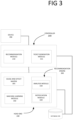
- FIG 3 illustrates another example of an autonomous instrument management system.
- the operation of the head-end 240 is described in more detail.
- FIG 3 includes the controller 200, which is configured to monitor the state, condition, or other aspect of a device that can facilitate production or processing of at least one product or other material.
- the head-end 240 is configured to provide automated error-correction, service recommendations, and other functionality based on analytics provided by the head-end 240.
- the controller 200 monitors the device by continually receiving measurement data from the device and comparing the measurement data to a reference value.
- the measurement data is not limited to a specific device this. Instead, it can be any industrial apparatus (measurement device), like a gas-flow meter, a gas chromatograph, a temperature sensor, a pressure sensor, am ultrasonic transducer, or any suitable general purpose measuring device.
- the measurement data can be stored in a database 299, or other suitable storage mechanism such as hardware, software, firmware, or any suitable combination of these.
- a ticket generation module 315 communicates with the head-end 240.
- the head-end 240 is configured to receive the communication from the ticket generation module 315 and to generate a ticket, which can be processed and utilize a recommendation engine 300.
- a new ticket number can be generated at the head-end 240, which can include with the ticket the details that were encapsulated in the package sent from the controller 200.
- the ticket number can be shared and stored at the head-end 240, for example it can be used to reference the ticket as it is processed through a traditional ticket processing system and until the problem is solved and the ticket is closed.
- the recommendation engine 300 is configured to provide autonomous advice on solving the error that is happening in the device using an analysis module 330, shown here as device 390.
- the recommendation engine 300 is also configured to return a detailed report to the ticket generation module 315 using a notification module 320.
- the report can include, for example, all of the information relevant to the device like data log files, historical data, and recommendations.
- the recommendation engine 300 can provide a most likely root cause and a most likely recommendations to solve this error situation back to the device. Both the most likely root cause and the most likely recommendations can be provided in clear text or other form to a user, device screen, or both.
- each recommendation has a calculated likelihood indicator between 0% and 100%. The recommendation with the highest likelihood, can be used by the recommendation engine 300 for the representation to the user, device screen, or elsewhere.
- the communication from the head-end 240 can also be used by a machine learning module 350.
- the machine learning module 350 can perform machine learning using a cause and effect matrix 305, which can also be included in the head-end 240.
- the cause and effect matrix 305 can have a table of other data structure that pairs a cause of a problem with a solution to the problem.
- the cause and effect matrix 305 can be updated, for example as better solutions are learned to existing problems. In this manner, the machine learning module 350 improves the cause and effect matrix 305 over time and this will in turn improve the performance of the controller 200, the recommendation module 210 and can be used to improve the solution data.
- automated feedback can be provided to the machine learning module 350 either from the ticket generation module 315 or another source.
- the automated feedback can include data associated with the actual field solutions for the device that can be used to update the cause and effect matrix 305, the recommendation engine 300, or both.
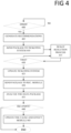
- FIG 4 is a flowchart that illustrates the operation of an autonomous instrument management system according to one embodiment.
- the system waits until there is an active error. When there is an active error, then at step 405, recommendations are generated. This could use a cause and effect module, for example.
- a package is sent to a ticketing system.
- the package could include, for example, raw and/or historical data associated with the device that triggered the error state in step 400.
- the ticketing system will resolve the device problem associated with the package in one of two manners: 1. Autonomously adjusting of the device parameters; or 2. Human interaction is required.
- the system will seek to resolve the problem at step 415 by either sending the error- and root cause description to the user for manual intervention or it will autonomously solve the problem by adjusting the device remotely.
- the system determines if the error has been fixed. If not, there error resolution step repeats at step 415.
- the ticketing system is updated at step 425 and a data package is sent to a recommendation module at step 430.
- the recommendation engine analyzes the data package.
- the recommendation engine determines whether or not the cause and effect module needs to be updated. If not, the process ends. Otherwise, the cause and effect module is updated at step 445 and the process ends.
- FIG 5 is a flowchart that illustrates the operation of an autonomous instrument management system according to another embodiment.
- the system waits until there is a signal will be received.
- the signal is analyzed. This signal can be sent, for example, when an ultrasonic transducer of a device is detected to be operating with a reduced accuracy.
- the system determines whether there is an active error. If not, the system continues to wait at step 500. When the error occurs at step 510, the system determines whether a parameter change is possible at step 515. When a parameter change is not possible, the system generates recommendations at step 540 (e.g., using a cause and effect table) and a data package is created and sent to a ticketing system, for example, at step 545. Thereafter, the process ends.
- recommendations e.g., using a cause and effect table
- a new parameter value can be calculated at step 520.
- the parameter is changed gradually in a step-wise manner as described in further detail with respect to Table 1.
- Table 1 Parameter Min Value Max Value Increment Step Decrement Step Parameter 1 Data 1 Data 2 Data 3 Data 4 Parameter 2 Data 5 Data 6 Data 7 Data 8
- the system determines whether the current parameter value of the device is at a threshold where the system cannot increase it anymore. This could occur, for example, by comparing the max value in Table 1 for a given device and determining whether the current value is equal or greater to the max value. If the current parameter value at step 525 is not at a threshold where the system cannot increase it anymore, then the system updates the connected device at step 530. At step 535, the system determines whether the error is solved. If so, the process ends. Otherwise, the process repeats at step 500 and the system thereafter waits for an additional signal at step 500.
- the cause and effect module includes weighting factors associated with each error or warning that originates from a device being monitored. Each factor can be rated on a scale from 0 to 10, for example, with 0 being of no influence and 10 indicating highly important for the outcome of the cause and effect module. Each possible error cause can also have a weighing factor on every possible error and warning. Each error cause can be rated, for example, on a scale from -10 to 10, with 0 being of no influence, -10 indicating high reduction of the impact and 10 indicating highly important for the outcome of the cause and effect module.
Landscapes
- Engineering & Computer Science (AREA)
- Physics & Mathematics (AREA)
- Quality & Reliability (AREA)
- General Physics & Mathematics (AREA)
- Theoretical Computer Science (AREA)
- General Engineering & Computer Science (AREA)
- Automation & Control Theory (AREA)
- Manufacturing & Machinery (AREA)
- Mathematical Physics (AREA)
- Health & Medical Sciences (AREA)
- Biomedical Technology (AREA)
- Fuzzy Systems (AREA)
- Testing And Monitoring For Control Systems (AREA)
Abstract
Description
- None
- Autonomous instrument management is used by a variety of industries to achieve a production level of consistency, economy, and safety which could not be achieved purely by human manual control. It is implemented widely in industries such as oil refining, pulp and paper manufacturing, chemical processing and power generating plants. For example, an instrument management system can sit in proximity to a plant and can manipulate a valve, start a motor, alter the settings of a device or sensor, or run a chiller or mixing unit as needed.
- Instrument management systems can also diagnose faults to prevent an unmanaged problem. An instrument management system can monitor a number of measuring devices to ensure their values are within an expected range for the device whose operation it is taking measurements of, for example. The measuring devices can obtain real-time values during operation of the process it is controlling. This can include, for example, temperature readings, pressure readings, gas flow readings, and the like. Instrument management systems can also report a status of a device or process it controls. This can include, for example, that a device is: out of fiscal reading; out of range; has a device error; and others.
- Determining the root cause of an error in a device is a complex and time-consuming task that requires deep knowledge and experience. Highly-skilled and trained technicians are usually required and are typically expensive and in short supply. What is needed is an instrument management that is capable of handling some portion of the faults in its controlled system without human intervention. This will not only make the system more cost-effective, but also reduce the downtime and increase the reliability of the entire system.
-
-
FIG 1 is a diagram of an autonomous instrument management system according to one embodiment. -
FIG 2 is a diagram of an autonomous instrument management system according to another embodiment. -
FIG 3 is a diagram of an autonomous instrument management system according to another embodiment. -
FIG 4 is a flowchart that illustrates the operation of an autonomous instrument management system according to one embodiment. -
FIG 5 is a flowchart that illustrates the operation of an autonomous instrument management system according to another embodiment. - One embodiment is an instrument management device, which includes a monitor module for a first device, wherein the first device is configured to obtain measurement data from a second device, to compare the measurement data to a reference value, and to send a signal when the measurement data in comparison to the reference indicates an error condition, a recommendation module to receive the signal from the monitoring module, to analyze the signal, and to generate one or more recommendations associated with the error condition by using a cause and effect module, the cause and effect module comprising a data structure having at least one row and at least one column, the recommendation module accessing a data item from one of the rows or one of the columns of the cause and effect module, a ticket generation module to receive the one or more recommendations including the data item, to obtain a resolution of the error condition by altering a state of the second device, and to generate a data package associated with the resolution of the error condition, and a machine learning module configured to use the package to determine whether to update the cause and effect module, and if so altering the data item in one of the rows or one of the columns.
- Another embodiment is a system, which includes a monitoring system for a first device, wherein the first device is configured to obtain measurement data from a second device, to compare the measurement data to a reference value, and to send a signal when the measurement data in comparison to the reference indicates an error condition, a recommendation system to receive the signal from the monitoring system, to analyze the signal, and to generate one or more recommendations associated with the error condition by using a cause and effect table, the cause and effect table comprising a data structure having at least one row and at least one column, the recommendation system accessing a data item from one of the rows or one of the columns of the cause and effect table, a ticket generation system to receive the one or more recommendations including the data item, to obtain a resolution of the error condition by altering a state of the second device, and to generate a data package associated with the resolution of the error condition, and a machine learning system configured to use the package to determine whether to update the cause and effect table, and if so altering the data item in one of the rows or one of the columns.
- In another embodiment, a method comprises obtaining measurement data from a device, comparing the measurement data to a reference value, receiving a signal when the measurement data in comparison to the reference value indicates an error condition, using a cause and effect table to generate one or more recommendations associated with the error condition by, the cause and effect table comprising a data structure having at least one row and at least one column, the step of using further comprising accessing a data item from one of the rows or one of the columns of the cause and effect table, obtaining a resolution of the error condition by altering a state of the device, generating a data package associated with the resolution of the error condition, and using the package to determine whether to update the cause and effect table, and if so altering the data item in one of the rows or one of the columns.
-
FIG 1 illustrates an example autonomousinstrument management system 100 according to this disclosure. As shown inFIG 1 , thesystem 100 includes various components that facilitate production or processing of at least one product or other material. For instance, thesystem 100 is used here to facilitate control over components in one or multiple plants, shown inFIG 1 as 101a, 101b, and 101n (referred to hereinafter as 101a-101n). Eachplant 101a-101n represents one or more processing facilities (or one or more portions thereof), such as one or more manufacturing facilities for producing at least one product or other material. In general, eachplant 101a-101n may implement one or more processes and can individually or collectively be referred to as a process system. A process system generally represents any system or portion thereof configured to process one or more products or other materials in some manner. - In
FIG 1 , thesystem 100 is implemented using the Purdue model of process control. In the Purdue model, "Level 0" may include one ormore sensors 102a and one ormore actuators 102b. Thesensors 102a andactuators 102b represent components in a process system that may perform any of a wide variety of functions. For example, thesensors 102a could measure a wide variety of characteristics in the process system, such as temperature, pressure, volume, or flow rate and could include such instruments as ultrasonic flow meters, turbines, orifices, Coriolis, gas chromatographs, P&T transmitters, flow computers, and the like. Also, theactuators 102b could alter a wide variety of characteristics in the process system. Thesensors 102a andactuators 102b could represent any other or additional components in any suitable process system. Each of thesensors 102a includes any suitable structure for measuring one or more characteristics in a process system. Each of theactuators 102b includes any suitable structure for operating on or affecting one or more conditions in a process system. The sensors and actuators may be generally referred to as field devices. - At least one
network 104 is coupled to thesensors 102a andactuators 102b. Thenetwork 104 facilitates interaction with thesensors 102a andactuators 102b. For example, thenetwork 104 could transport measurement data from thesensors 102a and provide control signals to theactuators 102b. Thenetwork 104 could represent any suitable network or combination of networks. As particular examples, thenetwork 104 could represent an Ethernet network, an electrical signal network (such as a HART or FOUNDATION FIELDBUS network), a pneumatic control signal network, or any other or additional type(s) of network(s). - In the Purdue model, "Level 1" may include one or
more controllers 106, which are coupled to thenetwork 104. Among other things, eachcontroller 106 may use the measurements from one ormore sensors 102a to control the operation of one ormore actuators 102b. For example, acontroller 106 could receive measurement data from one ormore sensors 102a and use the measurement data to generate control signals for one ormore actuators 102b.Multiple controllers 106 could also operate in redundant configurations, such as when onecontroller 106 operates as a primary controller while anothercontroller 106 operates as a backup controller (which synchronizes with the primary controller and can take over for the primary controller in the event of a fault with the primary controller). Eachcontroller 106 includes any suitable structure for interacting with one ormore sensors 102a and controlling one ormore actuators 102b. Eachcontroller 106 could, for example, represent a multivariable controller, such as a Robust Multivariable Predictive Control Technology (RMPCT) controller or other type of controller implementing model predictive control (MPC) or other advanced predictive control (APC). As a particular example, eachcontroller 106 could represent a computing device running a real-time operating system. - Two
networks 108 are coupled to thecontrollers 106. Thenetworks 108 facilitate interaction with thecontrollers 106, such as by transporting data to and from thecontrollers 106. Thenetworks 108 could represent any suitable networks or combination of networks. As particular examples, thenetworks 108 could represent a pair of Ethernet networks or a redundant pair of Ethernet networks, such as a FAULT TOLERANT ETHERNET (FTE) network from HONEYWELL INTERNATIONAL INC. - At least one switch/
firewall 110 couples thenetworks 108 to twonetworks 112. The switch/firewall 110 may transport traffic from one network to another. The switch/firewall 110 may also block traffic on one network from reaching another network. The switch/firewall 110 includes any suitable structure for providing communication between networks, such as a HONEYWELL CONTROL FIREWALL (CF9) device. Thenetworks 112 could represent any suitable networks, such as a pair of Ethernet networks or an FTE network. - In the Purdue model, "Level 2" may include one or more machine-
level controllers 114 coupled to thenetworks 112. The machine-level controllers 114 perform various functions to support the operation and control of thecontrollers 106,sensors 102a, andactuators 102b, which could be associated with a particular piece of industrial equipment (such as a boiler or other machine). For example, the machine-level controllers 114 could log information collected or generated by thecontrollers 106, such as measurement data from thesensors 102a or control signals for theactuators 102b. The machine-level controllers 114 could also execute applications that control the operation of thecontrollers 106, thereby controlling the operation of theactuators 102b. In addition, the machine-level controllers 114 could provide secure access to thecontrollers 106. Each of the machine-level controllers 114 includes any suitable structure for providing access to, control of, or operations related to a machine or other individual piece of equipment. Each of the machine-level controllers 114 could, for example, represent a server computing device running a MICROSOFT WINDOWS operating system. Although not shown, different machine-level controllers 114 could be used to control different pieces of equipment in a process system (where each piece of equipment is associated with one ormore controllers 106,sensors 102a, andactuators 102b). - One or
more operator stations 116 are coupled to thenetworks 112. Theoperator stations 116 represent computing or communication devices providing user access to the machine-level controllers 114, which could then provide user access to the controllers 106 (and possibly thesensors 102a andactuators 102b). As particular examples, theoperator stations 116 could allow users to review the operational history of thesensors 102a andactuators 102b using information collected by thecontrollers 106 and/or the machine-level controllers 114. Theoperator stations 116 could also allow the users to adjust the operation of thesensors 102a,actuators 102b,controllers 106, or machine-level controllers 114. In addition, theoperator stations 116 could receive and display warnings, alerts, or other messages or displays generated by thecontrollers 106 or the machine-level controllers 114. Each of theoperator stations 116 includes any suitable structure for supporting user access and control of one or more components in thesystem 100. Each of theoperator stations 116 could, for example, represent a computing device running a MICROSOFT WINDOWS operating system. - At least one router/
firewall 118 couples thenetworks 112 to twonetworks 120. The router/firewall 118 includes any suitable structure for providing communication between networks, such as a secure router or combination router/firewall. Thenetworks 120 could represent any suitable networks, such as a pair of Ethernet networks or an FTE network. - In the Purdue model, "Level 3" may include one or more unit-
level controllers 122 coupled to thenetworks 120. Each unit-level controller 122 is typically associated with a unit in a process system, which represents a collection of different machines operating together to implement at least part of a process. The unit-level controllers 122 perform various functions to support the operation and control of components in the lower levels. For example, the unit-level controllers 122 could log information collected or generated by the components in the lower levels, execute applications that control the components in the lower levels, and provide secure access to the components in the lower levels. Each of the unit-level controllers 122 includes any suitable structure for providing access to, control of, or operations related to one or more machines or other pieces of equipment in a process unit. Each of the unit-level controllers 122 could, for example, represent a server computing device running a MICROSOFT WINDOWS operating system. Although not shown, different unit-level controllers 122 could be used to control different units in a process system (where each unit is associated with one or more machine-level controllers 114,controllers 106,sensors 102a, andactuators 102b). - Access to the unit-
level controllers 122 may be provided by one ormore operator stations 124. Each of theoperator stations 124 includes any suitable structure for supporting user access and control of one or more components in thesystem 100. Each of theoperator stations 124 could, for example, represent a computing device running a MICROSOFT WINDOWS operating system. - At least one router/firewall 126 couples the
networks 120 to twonetworks 128. The router/firewall 126 includes any suitable structure for providing communication between networks, such as a secure router or combination router/firewall. Thenetworks 128 could represent any suitable networks, such as a pair of Ethernet networks or an FTE network. - In the Purdue model, "Level 4" may include one or more plant-
level controllers 130 coupled to thenetworks 128. Each plant-level controller 130 is typically associated with one of theplants 101a-101n, which may include one or more process units that implement the same, similar, or different processes. The plant-level controllers 130 perform various functions to support the operation and control of components in the lower levels. As particular examples, the plant-level controller 130 could execute one or more manufacturing execution system (MES) applications, scheduling applications, or other or additional plant or process control applications. Each of the plant-level controllers 130 includes any suitable structure for providing access to, control of, or operations related to one or more process units in a process plant. Each of the plant-level controllers 130 could, for example, represent a server computing device running a MICROSOFT WINDOWS operating system. - Access to the plant-
level controllers 130 may be provided by one ormore operator stations 132. Each of theoperator stations 132 includes any suitable structure for supporting user access and control of one or more components in thesystem 100. Each of theoperator stations 132 could, for example, represent a computing device running a MICROSOFT WINDOWS operating system. - At least one router/
firewall 134 couples thenetworks 128 to one ormore networks 136. The router/firewall 134 includes any suitable structure for providing communication between networks, such as a secure router or combination router/firewall. Thenetwork 136 could represent any suitable network, such as an enterprise-wide Ethernet or other network or all or a portion of a larger network (such as the Internet). - In the Purdue model, "Level 5" may include one or more enterprise-
level controllers 138 coupled to thenetwork 136. Each enterprise-level controller 138 is typically able to perform planning operations formultiple plants 101a-101n and to control various aspects of theplants 101a-101n. The enterprise-level controllers 138 can also perform various functions to support the operation and control of components in theplants 101a-101n. As particular examples, the enterprise-level controller 138 could execute one or more order processing applications, enterprise resource planning (ERP) applications, advanced planning and scheduling (APS) applications, or any other or additional enterprise control applications. Each of the enterprise-level controllers 138 includes any suitable structure for providing access to, control of, or operations related to the control of one or more plants. Each of the enterprise-level controllers 138 could, for example, represent a server computing device running a MICROSOFT WINDOWS operating system. In this document, the term "enterprise" refers to an organization having one or more plants or other processing facilities to be managed. Note that if asingle plant 101a is to be managed, the functionality of the enterprise-level controller 138 could be incorporated into the plant-level controller 130. - Access to the enterprise-
level controllers 138 may be provided by one ormore operator stations 140. Each of theoperator stations 140 includes any suitable structure for supporting user access and control of one or more components in thesystem 100. Each of theoperator stations 140 could, for example, represent a computing device running a MICROSOFT WINDOWS operating system. - Various levels of the Purdue model can include other components, such as one or more databases. The database(s) associated with each level could store any suitable information associated with that level or one or more other levels of the
system 100. For example, ahistorian 141 can be coupled to thenetwork 136. Thehistorian 141 could represent a component that stores various information about thesystem 100. Thehistorian 141 could, for instance, store information used during production scheduling and optimization. Thehistorian 141 represents any suitable structure for storing and facilitating retrieval of information. Although shown as a single centralized component coupled to thenetwork 136, thehistorian 141 could be located elsewhere in thesystem 100, or multiple historians could be distributed in different locations in thesystem 100. - In particular embodiments, the various controllers and operator stations in
FIG 1 may represent computing devices. For example, each of the controllers could include one ormore processing devices 142 and one ormore memories 144 for storing instructions and data used, generated, or collected by the processing device(s) 142. Each of the controllers could also include at least onenetwork interface 146, such as one or more Ethernet interfaces or wireless transceivers. Also, each of the operator stations could include one ormore processing devices 148 and one ormore memories 150 for storing instructions and data used, generated, or collected by the processing device(s) 148. Each of the operator stations could also include at least onenetwork interface 152, such as one or more Ethernet interfaces or wireless transceivers. -
FIG 2 illustrates another example of an autonomous instrument management system.FIG 2 includes acontroller 200 which can be any suitable controller, such as those described with respect toFIG 1 or others. In one example, thecontroller 200 is configured to monitor the state, condition, or other aspect of a device 250. The device 250 can be any suitable device that can facilitate production or processing of at least one product or other material. In one example, this includes a gas-flow meter or an ultrasonic transducer. In another example, thecontroller 200 can use a head-end 240 to provide automated error-correction, service recommendations, and other functionality based on analytics provided by the head-end 240. The device 250 can be any suitable device that has a microprocessor and is capable of storing bulk data and/or performing analytics on the bulk data. In one example, the device 250 is a measuring device, such as a volume and/or mass flow measuring device or meter. - In operation, the
controller 200 monitors the device 250 using amonitor module 205. Themonitor module 205 continually receives measurement data from the device 250 and compares the measurement data to a reference value. This could be, for example, a volume flow meter reporting a volume measurement to themonitor module 205 and the monitor module comparing the volume measurement to measurement data that represents a normal operating range. The measurement data can be stored in adatabase 299, or other suitable storage mechanism such as hardware, software, firmware, or any suitable combination of these. When the measurement data and the reference values indicate that the device 250 is operating out of range, or otherwise is in a state that requires some action, asignal 290 is sent to arecommendation module 210. This could happen when an ultrasonic transducer of the device 250 has a reference value indicative of a reduced accuracy. Alternatively, this situation can occur when any generic sensor, instrument, or device is operating out of range when compared to an expected reference value. - The
recommendation module 210 can accesssolution data 220, where it is configured to provide a solution to themonitor module 205 and is capable of enabling thecontroller 200 to bring the device 250 back into range or otherwise restore its normal operating characteristics. Aticket generation module 215 can also be used, which is configured to perform a process that resolves the error condition that caused the origination of the ticket. Theticket generation module 215 can be configured to receive thesignal 290 from therecommendation module 210. In one example, thecontroller 200 encaplsulates the data associated with the error condition into a package and sends it to the head-end 240. A package can be included on a per device basis and can also be sent with a pre-defined delay, which can allow the system to stabilize on the error situation before sending it to theticket generation module 215. For example, in the case of a short-lived disturbance that simply disappears, no package may need to be sent. It is also possible that multiple errors and warnings occur based on one error situation. (e.g., a broken sensor cable will result in many different errors), in which case the package could include the multiple errors, or multiple packages can be sent. In another example, the package includes detailed device information collected by thecontroller 200, like name and serial number of the device, location, log (raw data) files, recommendation text, and more. - The head-
end 240 is configured to receive the package and to perform machine learning using the package with amachine learning module 225. A cause andeffect module 230 can also be included in the head-end 240. The cause andeffect module 230 can have a table of other data structure that pairs a cause of a problem with a solution to the problem. By utilizing themachine learning module 225 continually over time, the cause andeffect module 230 can be updated, for example as better solutions are learned to existing problems. In one example, the cause and effect module 305 is configured to have one or more of any active status, alarm, and warning messages for the device 250. In this manner, themachine learning module 225 improves the cause and effect table 230 over time and this will in turn improve the performance of thecontroller 200, therecommendation module 210 and can be used to improve thesolution data 220. -
FIG 3 illustrates another example of an autonomous instrument management system. InFIG 3 , the operation of the head-end 240 is described in more detail.FIG 3 includes thecontroller 200, which is configured to monitor the state, condition, or other aspect of a device that can facilitate production or processing of at least one product or other material. The head-end 240 is configured to provide automated error-correction, service recommendations, and other functionality based on analytics provided by the head-end 240. In operation, thecontroller 200 monitors the device by continually receiving measurement data from the device and comparing the measurement data to a reference value. The measurement data is not limited to a specific device this. Instead, it can be any industrial apparatus (measurement device), like a gas-flow meter, a gas chromatograph, a temperature sensor, a pressure sensor, am ultrasonic transducer, or any suitable general purpose measuring device. - The measurement data can be stored in a
database 299, or other suitable storage mechanism such as hardware, software, firmware, or any suitable combination of these. - When the measurement data and the reference values indicate that the device is operating out of range, or otherwise is in a state that requires some action, a
ticket generation module 315 communicates with the head-end 240. The head-end 240 is configured to receive the communication from theticket generation module 315 and to generate a ticket, which can be processed and utilize arecommendation engine 300. In one example, a new ticket number can be generated at the head-end 240, which can include with the ticket the details that were encapsulated in the package sent from thecontroller 200. The ticket number can be shared and stored at the head-end 240, for example it can be used to reference the ticket as it is processed through a traditional ticket processing system and until the problem is solved and the ticket is closed. - The
recommendation engine 300 is configured to provide autonomous advice on solving the error that is happening in the device using ananalysis module 330, shown here asdevice 390. Therecommendation engine 300 is also configured to return a detailed report to theticket generation module 315 using anotification module 320. The report can include, for example, all of the information relevant to the device like data log files, historical data, and recommendations. In one embodiment, therecommendation engine 300 can provide a most likely root cause and a most likely recommendations to solve this error situation back to the device. Both the most likely root cause and the most likely recommendations can be provided in clear text or other form to a user, device screen, or both. In another example, each recommendation has a calculated likelihood indicator between 0% and 100%. The recommendation with the highest likelihood, can be used by therecommendation engine 300 for the representation to the user, device screen, or elsewhere. - The communication from the head-
end 240 can also be used by amachine learning module 350. Themachine learning module 350 can perform machine learning using a cause and effect matrix 305, which can also be included in the head-end 240. The cause and effect matrix 305 can have a table of other data structure that pairs a cause of a problem with a solution to the problem. By utilizing themachine learning module 350 continually over time, the cause and effect matrix 305 can be updated, for example as better solutions are learned to existing problems. In this manner, themachine learning module 350 improves the cause and effect matrix 305 over time and this will in turn improve the performance of thecontroller 200, therecommendation module 210 and can be used to improve the solution data. In one example, automated feedback can be provided to themachine learning module 350 either from theticket generation module 315 or another source. The automated feedback can include data associated with the actual field solutions for the device that can be used to update the cause and effect matrix 305, therecommendation engine 300, or both. -
FIG 4 is a flowchart that illustrates the operation of an autonomous instrument management system according to one embodiment. Atstep 400, the system waits until there is an active error. When there is an active error, then atstep 405, recommendations are generated. This could use a cause and effect module, for example. Thereafter, atstep 410, a package is sent to a ticketing system. The package could include, for example, raw and/or historical data associated with the device that triggered the error state instep 400. In one example, the ticketing system will resolve the device problem associated with the package in one of two manners: 1. Autonomously adjusting of the device parameters; or 2. Human interaction is required. The system will seek to resolve the problem at step 415 by either sending the error- and root cause description to the user for manual intervention or it will autonomously solve the problem by adjusting the device remotely. - At
step 420, the system determines if the error has been fixed. If not, there error resolution step repeats at step 415. When the error condition is fixed, the ticketing system is updated atstep 425 and a data package is sent to a recommendation module atstep 430. Atstep 435, the recommendation engine analyzes the data package. Atstep 440, the recommendation engine determines whether or not the cause and effect module needs to be updated. If not, the process ends. Otherwise, the cause and effect module is updated at step 445 and the process ends. -
FIG 5 is a flowchart that illustrates the operation of an autonomous instrument management system according to another embodiment. Atstep 500, the system waits until there is a signal will be received. Atstep 505, the signal is analyzed. This signal can be sent, for example, when an ultrasonic transducer of a device is detected to be operating with a reduced accuracy. Atstep 510, the system determines whether there is an active error. If not, the system continues to wait atstep 500. When the error occurs atstep 510, the system determines whether a parameter change is possible atstep 515. When a parameter change is not possible, the system generates recommendations at step 540 (e.g., using a cause and effect table) and a data package is created and sent to a ticketing system, for example, at step 545. Thereafter, the process ends. - When a parameter change is possible at step 515 a new parameter value can be calculated at
step 520. In one example the parameter is changed gradually in a step-wise manner as described in further detail with respect to Table 1.Table 1 Parameter Min Value Max Value Increment Step Decrement Step Parameter 1 Data 1 Data 2 Data 3 Data 4 Parameter 2 Data 5 Data 6 Data 7 Data 8 - At
step 525, the system determines whether the current parameter value of the device is at a threshold where the system cannot increase it anymore. This could occur, for example, by comparing the max value in Table 1 for a given device and determining whether the current value is equal or greater to the max value. If the current parameter value atstep 525 is not at a threshold where the system cannot increase it anymore, then the system updates the connected device atstep 530. Atstep 535, the system determines whether the error is solved. If so, the process ends. Otherwise, the process repeats atstep 500 and the system thereafter waits for an additional signal atstep 500. - Table 1, and others, can be used to instruct the system on what values to use when doing a step-wise adjustment for a device. In another example, the cause and effect module includes weighting factors associated with each error or warning that originates from a device being monitored. Each factor can be rated on a scale from 0 to 10, for example, with 0 being of no influence and 10 indicating highly important for the outcome of the cause and effect module. Each possible error cause can also have a weighing factor on every possible error and warning. Each error cause can be rated, for example, on a scale from -10 to 10, with 0 being of no influence, -10 indicating high reduction of the impact and 10 indicating highly important for the outcome of the cause and effect module.
- Although the subject matter has been described in language specific to structural features and/or methodological acts, it is to be understood that the subject matter defined in the appended claims is not necessarily limited to the specific features or acts described above. Rather, the specific features and acts described above are disclosed as example forms of implementing the claims.
Claims (10)
- An instrument management device comprising:a monitor module (205) for a first device, wherein the first device is configured to obtain measurement data from a second device, to compare the measurement data to a reference value, and to send a signal when the measurement data in comparison to the reference indicates an error condition;a recommendation module (210) to receive the signal from the monitoring module (205), to analyze the signal, and to generate one or more recommendations associated with the error condition by using a cause and effect module (230), the cause and effect module (230) comprising a data structure having at least one row and at least one column, the recommendation module (210) accessing a data item from one of the rows or one of the columns of the cause and effect module (230);a ticket generation module (215) to receive the one or more recommendations including the data item, to obtain a resolution of the error condition by altering a state of the second device, and to generate a data package associated with the resolution of the error condition; anda machine learning module (225) configured to use the package to determine whether to update the cause and effect module (230), and if so altering the data item in one of the rows or one of the columns.
- The device of claim 1, wherein the first device has a microprocessor and a memory.
- The device of claim 2, wherein the measurement data is associated with a general purpose measuring device.
- The device of claim 3, wherein the error condition indicates a specific error.
- A system comprising:a monitoring system (205) for a first device, wherein the first device is configured to obtain measurement data from a second device, to compare the measurement data to a reference value, and to send a signal when the measurement data in comparison to the reference indicates an error condition;a recommendation system (210) to receive the signal from the monitoring system (205), to analyze the signal, and to generate one or more recommendations associated with the error condition by using a cause and effect table (230), the cause and effect table (230) comprising a data structure having at least one row and at least one column, the recommendation system (210) accessing a data item from one of the rows or one of the columns of the cause and effect table (230);a ticket generation system (215) to receive the one or more recommendations including the data item, to obtain a resolution of the error condition by altering a state of the second device, and to generate a data package associated with the resolution of the error condition; anda machine learning system (225) configured to use the package to determine whether to update the cause and effect table (230), and if so altering the data item in one of the rows or one of the columns.
- The system of claim 5, wherein the first device has a microprocessor and a memory.
- The system of claim 6, wherein the measurement data is associated with a general purpose measuring device.
- The system of claim 7, wherein the error condition indicates a specific error.
- A method comprising:obtaining measurement data from a device;comparing the measurement data to a reference value;receiving a signal when the measurement data in comparison to the reference value indicates an error condition;using a cause and effect table (230) to generate one or more recommendations associated with the error condition by, the cause and effect table (230) comprising a data structure having at least one row and at least one column, the step of using further comprising accessing a data item from one of the rows or one of the columns of the cause and effect table (230);obtaining a resolution of the error condition by altering a state of the device;generating a data package associated with the resolution of the error condition; andusing the package to determine whether to update the cause and effect table (230), and if so altering the data item in one of the rows or one of the columns.
- The method of claim 9, wherein the step of using the package further comprises, determining whether the reference value is sufficiently close to an operating range for a second device associated with the device.
Applications Claiming Priority (1)
| Application Number | Priority Date | Filing Date | Title |
|---|---|---|---|
| US17/447,091 US12228916B2 (en) | 2021-09-08 | 2021-09-08 | Autonomous instrument management |
Publications (2)
| Publication Number | Publication Date |
|---|---|
| EP4148521A1 true EP4148521A1 (en) | 2023-03-15 |
| EP4148521B1 EP4148521B1 (en) | 2024-12-11 |
Family
ID=83318890
Family Applications (1)
| Application Number | Title | Priority Date | Filing Date |
|---|---|---|---|
| EP22191592.9A Active EP4148521B1 (en) | 2021-09-08 | 2022-08-23 | Autonomous instrument management |
Country Status (4)
| Country | Link |
|---|---|
| US (1) | US12228916B2 (en) |
| EP (1) | EP4148521B1 (en) |
| CN (1) | CN115774424B (en) |
| CA (1) | CA3172607C (en) |
Citations (3)
| Publication number | Priority date | Publication date | Assignee | Title |
|---|---|---|---|---|
| US20040225475A1 (en) * | 2002-11-25 | 2004-11-11 | General Electric Company | Method, system and computer product for performing failure mode and effects analysis throughout the product life cycle |
| EP3059676A1 (en) * | 2015-02-20 | 2016-08-24 | Siemens Aktiengesellschaft | A method and apparatus for analyzing the availability of a system, in particular of a safety critical system |
| US20200312122A1 (en) * | 2019-03-27 | 2020-10-01 | Fisher Controls International Llc | Apparatus and methods for alert management in process control instrumentation |
Family Cites Families (28)
| Publication number | Priority date | Publication date | Assignee | Title |
|---|---|---|---|---|
| US5224206A (en) * | 1989-12-01 | 1993-06-29 | Digital Equipment Corporation | System and method for retrieving justifiably relevant cases from a case library |
| US7797062B2 (en) * | 2001-08-10 | 2010-09-14 | Rockwell Automation Technologies, Inc. | System and method for dynamic multi-objective optimization of machine selection, integration and utilization |
| US20090204237A1 (en) * | 2001-08-10 | 2009-08-13 | Rockwell Automation Technologies, Inc. | System and method for dynamic multi-objective optimization of machine selection, integration and utilization |
| GB0127551D0 (en) * | 2001-11-16 | 2002-01-09 | Abb Ab | Analysing events |
| US6655754B2 (en) * | 2002-04-02 | 2003-12-02 | Ford Global Technologies, Llc | Vehicle brake system having adaptive torque control |
| US20090055684A1 (en) * | 2007-08-23 | 2009-02-26 | Jamjoom Hani T | Method and apparatus for efficient problem resolution via incrementally constructed causality model based on history data |
| US8462619B2 (en) * | 2009-12-10 | 2013-06-11 | At&T Intellectual Property I, L.P. | Systems and methods for providing fault detection and management |
| US20120166874A1 (en) * | 2010-12-23 | 2012-06-28 | Timothy Bernardez | Wireless Device Expert System |
| US9002775B1 (en) * | 2011-09-02 | 2015-04-07 | Lockheed Martin Corporation | Systems and methods for estimating a remaining useful life of an item |
| CN102508907B (en) * | 2011-11-11 | 2013-11-20 | 北京航空航天大学 | Dynamic recommendation method based on training set optimization for recommendation system |
| US9645575B2 (en) * | 2013-11-27 | 2017-05-09 | Adept Ai Systems Inc. | Method and apparatus for artificially intelligent model-based control of dynamic processes using probabilistic agents |
| US9483342B2 (en) | 2014-03-20 | 2016-11-01 | Siemens Aktiengesellschaft | Supporting failure mode and effects analysis |
| US9733629B2 (en) * | 2014-07-21 | 2017-08-15 | Honeywell International Inc. | Cascaded model predictive control (MPC) approach for plantwide control and optimization |
| EP3210085A4 (en) * | 2014-10-24 | 2018-06-27 | Honeywell International Inc. | Apparatus and method for calculating proxy limits to support cascaded model predictive control (mpc) |
| US10176032B2 (en) | 2014-12-01 | 2019-01-08 | Uptake Technologies, Inc. | Subsystem health score |
| US20170082480A1 (en) * | 2015-09-21 | 2017-03-23 | Honeywell International Inc. | Real-time condition based monitoring (cbm) based ultrasonic meter (usm) accuracy performance detection and notification |
| JP6457369B2 (en) * | 2015-09-30 | 2019-01-23 | ファナック株式会社 | Machine learning device and motor control device having function of automatically adjusting parameters |
| US20180284758A1 (en) * | 2016-05-09 | 2018-10-04 | StrongForce IoT Portfolio 2016, LLC | Methods and systems for industrial internet of things data collection for equipment analysis in an upstream oil and gas environment |
| JP6890382B2 (en) * | 2016-05-23 | 2021-06-18 | ルネサスエレクトロニクス株式会社 | Production system |
| US11237546B2 (en) * | 2016-06-15 | 2022-02-01 | Strong Force loT Portfolio 2016, LLC | Method and system of modifying a data collection trajectory for vehicles |
| CN106598791B (en) | 2016-09-12 | 2020-08-21 | 湖南微软创新中心有限公司 | A preventive identification method for industrial equipment faults based on machine learning |
| JP6490127B2 (en) * | 2017-03-15 | 2019-03-27 | ファナック株式会社 | Machine learning device, servo control device, servo control system, and machine learning method |
| US10921801B2 (en) * | 2017-08-02 | 2021-02-16 | Strong Force loT Portfolio 2016, LLC | Data collection systems and methods for updating sensed parameter groups based on pattern recognition |
| US10769570B2 (en) * | 2017-12-27 | 2020-09-08 | Accenture Global Solutions Limited | Artificial intelligence based risk and knowledge management |
| US10740168B2 (en) | 2018-03-29 | 2020-08-11 | International Business Machines Corporation | System maintenance using unified cognitive root cause analysis for multiple domains |
| US11599407B2 (en) * | 2018-09-27 | 2023-03-07 | Siemens Healthcare Diagnostics Inc. | Method for deterministically reporting cause and effect in software systems |
| US11694063B2 (en) * | 2018-10-25 | 2023-07-04 | Billips, Inc. | Machine-based prediction of visitation caused by viewing |
| US10678196B1 (en) * | 2020-01-27 | 2020-06-09 | King Abdulaziz University | Soft sensing of a nonlinear and multimode processes based on semi-supervised weighted Gaussian regression |
-
2021
- 2021-09-08 US US17/447,091 patent/US12228916B2/en active Active
-
2022
- 2022-08-18 CN CN202210994789.1A patent/CN115774424B/en active Active
- 2022-08-23 EP EP22191592.9A patent/EP4148521B1/en active Active
- 2022-09-07 CA CA3172607A patent/CA3172607C/en active Active
Patent Citations (3)
| Publication number | Priority date | Publication date | Assignee | Title |
|---|---|---|---|---|
| US20040225475A1 (en) * | 2002-11-25 | 2004-11-11 | General Electric Company | Method, system and computer product for performing failure mode and effects analysis throughout the product life cycle |
| EP3059676A1 (en) * | 2015-02-20 | 2016-08-24 | Siemens Aktiengesellschaft | A method and apparatus for analyzing the availability of a system, in particular of a safety critical system |
| US20200312122A1 (en) * | 2019-03-27 | 2020-10-01 | Fisher Controls International Llc | Apparatus and methods for alert management in process control instrumentation |
Also Published As
| Publication number | Publication date |
|---|---|
| US20230070826A1 (en) | 2023-03-09 |
| CN115774424B (en) | 2025-10-28 |
| CA3172607A1 (en) | 2023-03-08 |
| CN115774424A (en) | 2023-03-10 |
| US12228916B2 (en) | 2025-02-18 |
| CA3172607C (en) | 2026-04-21 |
| EP4148521B1 (en) | 2024-12-11 |
Similar Documents
| Publication | Publication Date | Title |
|---|---|---|
| EP3751373B1 (en) | Predictive troubleshooting for abnormal plant operations | |
| US20180074483A1 (en) | Method and Apparatus for Assessing the Collective Health of Multiple Process Control Systems | |
| US20040181364A1 (en) | Generation of data indicative of machine operational condition | |
| US20170053224A1 (en) | System and method for providing multi-site visualization and scoring of performance against service agreement | |
| US20210333789A1 (en) | Method and apparatus for real time model predictive control operator support in industrial process control and automation systems | |
| US10235447B2 (en) | Method and system for co-operative intelligent HMIs for effective process operations | |
| US10699556B1 (en) | System and method for plant operation gap analysis and guidance solution | |
| US10139788B2 (en) | Remote data analytics to predict system components or device failure | |
| WO2019226846A1 (en) | Competency gap identification of an operators response to various process control and maintenance conditions | |
| US20170053225A1 (en) | System and method for providing visualization of performance against service agreement | |
| US7948492B2 (en) | Apparatus and method for visualization of operating status in a process control system | |
| EP4148521B1 (en) | Autonomous instrument management | |
| US10536534B2 (en) | System and method for providing visual feedback in site-related service activity roadmap | |
| US20170052957A1 (en) | System and method for providing high-level graphical feedback related to overall site performance and health | |
| US11334061B2 (en) | Method to detect skill gap of operators making frequent inadvertent changes to the process variables | |
| CN111837082A (en) | Ultrasonic flowmeter pre-diagnosis using near real-time conditions |
Legal Events
| Date | Code | Title | Description |
|---|---|---|---|
| PUAI | Public reference made under article 153(3) epc to a published international application that has entered the european phase |
Free format text: ORIGINAL CODE: 0009012 |
|
| STAA | Information on the status of an ep patent application or granted ep patent |
Free format text: STATUS: REQUEST FOR EXAMINATION WAS MADE |
|
| 17P | Request for examination filed |
Effective date: 20220823 |
|
| AK | Designated contracting states |
Kind code of ref document: A1 Designated state(s): AL AT BE BG CH CY CZ DE DK EE ES FI FR GB GR HR HU IE IS IT LI LT LU LV MC MK MT NL NO PL PT RO RS SE SI SK SM TR |
|
| GRAP | Despatch of communication of intention to grant a patent |
Free format text: ORIGINAL CODE: EPIDOSNIGR1 |
|
| STAA | Information on the status of an ep patent application or granted ep patent |
Free format text: STATUS: GRANT OF PATENT IS INTENDED |
|
| INTG | Intention to grant announced |
Effective date: 20240730 |
|
| GRAS | Grant fee paid |
Free format text: ORIGINAL CODE: EPIDOSNIGR3 |
|
| GRAA | (expected) grant |
Free format text: ORIGINAL CODE: 0009210 |
|
| STAA | Information on the status of an ep patent application or granted ep patent |
Free format text: STATUS: THE PATENT HAS BEEN GRANTED |
|
| AK | Designated contracting states |
Kind code of ref document: B1 Designated state(s): AL AT BE BG CH CY CZ DE DK EE ES FI FR GB GR HR HU IE IS IT LI LT LU LV MC MK MT NL NO PL PT RO RS SE SI SK SM TR |
|
| REG | Reference to a national code |
Ref country code: GB Ref legal event code: FG4D |
|
| REG | Reference to a national code |
Ref country code: CH Ref legal event code: EP |
|
| REG | Reference to a national code |
Ref country code: DE Ref legal event code: R096 Ref document number: 602022008565 Country of ref document: DE |
|
| REG | Reference to a national code |
Ref country code: IE Ref legal event code: FG4D |
|
| REG | Reference to a national code |
Ref country code: LT Ref legal event code: MG9D |
|
| PG25 | Lapsed in a contracting state [announced via postgrant information from national office to epo] |
Ref country code: HR Free format text: LAPSE BECAUSE OF FAILURE TO SUBMIT A TRANSLATION OF THE DESCRIPTION OR TO PAY THE FEE WITHIN THE PRESCRIBED TIME-LIMIT Effective date: 20241211 |
|
| PG25 | Lapsed in a contracting state [announced via postgrant information from national office to epo] |
Ref country code: FI Free format text: LAPSE BECAUSE OF FAILURE TO SUBMIT A TRANSLATION OF THE DESCRIPTION OR TO PAY THE FEE WITHIN THE PRESCRIBED TIME-LIMIT Effective date: 20241211 |
|
| PG25 | Lapsed in a contracting state [announced via postgrant information from national office to epo] |
Ref country code: BG Free format text: LAPSE BECAUSE OF FAILURE TO SUBMIT A TRANSLATION OF THE DESCRIPTION OR TO PAY THE FEE WITHIN THE PRESCRIBED TIME-LIMIT Effective date: 20241211 |
|
| REG | Reference to a national code |
Ref country code: NL Ref legal event code: MP Effective date: 20241211 |
|
| PG25 | Lapsed in a contracting state [announced via postgrant information from national office to epo] |
Ref country code: ES Free format text: LAPSE BECAUSE OF FAILURE TO SUBMIT A TRANSLATION OF THE DESCRIPTION OR TO PAY THE FEE WITHIN THE PRESCRIBED TIME-LIMIT Effective date: 20241211 |
|
| PG25 | Lapsed in a contracting state [announced via postgrant information from national office to epo] |
Ref country code: NO Free format text: LAPSE BECAUSE OF FAILURE TO SUBMIT A TRANSLATION OF THE DESCRIPTION OR TO PAY THE FEE WITHIN THE PRESCRIBED TIME-LIMIT Effective date: 20250311 |
|
| PG25 | Lapsed in a contracting state [announced via postgrant information from national office to epo] |
Ref country code: GR Free format text: LAPSE BECAUSE OF FAILURE TO SUBMIT A TRANSLATION OF THE DESCRIPTION OR TO PAY THE FEE WITHIN THE PRESCRIBED TIME-LIMIT Effective date: 20250312 Ref country code: LV Free format text: LAPSE BECAUSE OF FAILURE TO SUBMIT A TRANSLATION OF THE DESCRIPTION OR TO PAY THE FEE WITHIN THE PRESCRIBED TIME-LIMIT Effective date: 20241211 |
|
| PG25 | Lapsed in a contracting state [announced via postgrant information from national office to epo] |
Ref country code: RS Free format text: LAPSE BECAUSE OF FAILURE TO SUBMIT A TRANSLATION OF THE DESCRIPTION OR TO PAY THE FEE WITHIN THE PRESCRIBED TIME-LIMIT Effective date: 20250311 |
|
| PG25 | Lapsed in a contracting state [announced via postgrant information from national office to epo] |
Ref country code: NL Free format text: LAPSE BECAUSE OF FAILURE TO SUBMIT A TRANSLATION OF THE DESCRIPTION OR TO PAY THE FEE WITHIN THE PRESCRIBED TIME-LIMIT Effective date: 20241211 |
|
| REG | Reference to a national code |
Ref country code: AT Ref legal event code: MK05 Ref document number: 1750889 Country of ref document: AT Kind code of ref document: T Effective date: 20241211 |
|
| PG25 | Lapsed in a contracting state [announced via postgrant information from national office to epo] |
Ref country code: SM Free format text: LAPSE BECAUSE OF FAILURE TO SUBMIT A TRANSLATION OF THE DESCRIPTION OR TO PAY THE FEE WITHIN THE PRESCRIBED TIME-LIMIT Effective date: 20241211 |
|
| PG25 | Lapsed in a contracting state [announced via postgrant information from national office to epo] |
Ref country code: PL Free format text: LAPSE BECAUSE OF FAILURE TO SUBMIT A TRANSLATION OF THE DESCRIPTION OR TO PAY THE FEE WITHIN THE PRESCRIBED TIME-LIMIT Effective date: 20241211 |
|
| PG25 | Lapsed in a contracting state [announced via postgrant information from national office to epo] |
Ref country code: IS Free format text: LAPSE BECAUSE OF FAILURE TO SUBMIT A TRANSLATION OF THE DESCRIPTION OR TO PAY THE FEE WITHIN THE PRESCRIBED TIME-LIMIT Effective date: 20250411 |
|
| PG25 | Lapsed in a contracting state [announced via postgrant information from national office to epo] |
Ref country code: PT Free format text: LAPSE BECAUSE OF FAILURE TO SUBMIT A TRANSLATION OF THE DESCRIPTION OR TO PAY THE FEE WITHIN THE PRESCRIBED TIME-LIMIT Effective date: 20250411 |
|
| PG25 | Lapsed in a contracting state [announced via postgrant information from national office to epo] |
Ref country code: EE Free format text: LAPSE BECAUSE OF FAILURE TO SUBMIT A TRANSLATION OF THE DESCRIPTION OR TO PAY THE FEE WITHIN THE PRESCRIBED TIME-LIMIT Effective date: 20241211 |
|
| PG25 | Lapsed in a contracting state [announced via postgrant information from national office to epo] |
Ref country code: RO Free format text: LAPSE BECAUSE OF FAILURE TO SUBMIT A TRANSLATION OF THE DESCRIPTION OR TO PAY THE FEE WITHIN THE PRESCRIBED TIME-LIMIT Effective date: 20241211 Ref country code: AT Free format text: LAPSE BECAUSE OF FAILURE TO SUBMIT A TRANSLATION OF THE DESCRIPTION OR TO PAY THE FEE WITHIN THE PRESCRIBED TIME-LIMIT Effective date: 20241211 |
|
| PG25 | Lapsed in a contracting state [announced via postgrant information from national office to epo] |
Ref country code: SK Free format text: LAPSE BECAUSE OF FAILURE TO SUBMIT A TRANSLATION OF THE DESCRIPTION OR TO PAY THE FEE WITHIN THE PRESCRIBED TIME-LIMIT Effective date: 20241211 |
|
| PG25 | Lapsed in a contracting state [announced via postgrant information from national office to epo] |
Ref country code: CZ Free format text: LAPSE BECAUSE OF FAILURE TO SUBMIT A TRANSLATION OF THE DESCRIPTION OR TO PAY THE FEE WITHIN THE PRESCRIBED TIME-LIMIT Effective date: 20241211 |
|
| PG25 | Lapsed in a contracting state [announced via postgrant information from national office to epo] |
Ref country code: IT Free format text: LAPSE BECAUSE OF FAILURE TO SUBMIT A TRANSLATION OF THE DESCRIPTION OR TO PAY THE FEE WITHIN THE PRESCRIBED TIME-LIMIT Effective date: 20241211 |
|
| PG25 | Lapsed in a contracting state [announced via postgrant information from national office to epo] |
Ref country code: SE Free format text: LAPSE BECAUSE OF FAILURE TO SUBMIT A TRANSLATION OF THE DESCRIPTION OR TO PAY THE FEE WITHIN THE PRESCRIBED TIME-LIMIT Effective date: 20241211 |
|
| REG | Reference to a national code |
Ref country code: DE Ref legal event code: R097 Ref document number: 602022008565 Country of ref document: DE |
|
| PG25 | Lapsed in a contracting state [announced via postgrant information from national office to epo] |
Ref country code: DK Free format text: LAPSE BECAUSE OF FAILURE TO SUBMIT A TRANSLATION OF THE DESCRIPTION OR TO PAY THE FEE WITHIN THE PRESCRIBED TIME-LIMIT Effective date: 20241211 |
|
| PGFP | Annual fee paid to national office [announced via postgrant information from national office to epo] |
Ref country code: DE Payment date: 20250827 Year of fee payment: 4 |
|
| PLBE | No opposition filed within time limit |
Free format text: ORIGINAL CODE: 0009261 |
|
| STAA | Information on the status of an ep patent application or granted ep patent |
Free format text: STATUS: NO OPPOSITION FILED WITHIN TIME LIMIT |
|
| REG | Reference to a national code |
Ref country code: CH Ref legal event code: L10 Free format text: ST27 STATUS EVENT CODE: U-0-0-L10-L00 (AS PROVIDED BY THE NATIONAL OFFICE) Effective date: 20251022 |
|
| 26N | No opposition filed |
Effective date: 20250912 |
|
| REG | Reference to a national code |
Ref country code: CH Ref legal event code: H13 Free format text: ST27 STATUS EVENT CODE: U-0-0-H10-H13 (AS PROVIDED BY THE NATIONAL OFFICE) Effective date: 20260324 |
|
| PG25 | Lapsed in a contracting state [announced via postgrant information from national office to epo] |
Ref country code: MC Free format text: LAPSE BECAUSE OF FAILURE TO SUBMIT A TRANSLATION OF THE DESCRIPTION OR TO PAY THE FEE WITHIN THE PRESCRIBED TIME-LIMIT Effective date: 20241211 |
|
| PG25 | Lapsed in a contracting state [announced via postgrant information from national office to epo] |
Ref country code: LU Free format text: LAPSE BECAUSE OF NON-PAYMENT OF DUE FEES Effective date: 20250823 |
|
| PG25 | Lapsed in a contracting state [announced via postgrant information from national office to epo] |
Ref country code: CH Free format text: LAPSE BECAUSE OF NON-PAYMENT OF DUE FEES Effective date: 20250831 |