EP4148492A1 - Phase shifter architecture for optical beam steering devices - Google Patents
Phase shifter architecture for optical beam steering devices Download PDFInfo
- Publication number
- EP4148492A1 EP4148492A1 EP22193906.9A EP22193906A EP4148492A1 EP 4148492 A1 EP4148492 A1 EP 4148492A1 EP 22193906 A EP22193906 A EP 22193906A EP 4148492 A1 EP4148492 A1 EP 4148492A1
- Authority
- EP
- European Patent Office
- Prior art keywords
- phase shifters
- optical beam
- output
- optical
- network
- Prior art date
- Legal status (The legal status is an assumption and is not a legal conclusion. Google has not performed a legal analysis and makes no representation as to the accuracy of the status listed.)
- Granted
Links
Images




Classifications
-
- G—PHYSICS
- G02—OPTICS
- G02F—OPTICAL DEVICES OR ARRANGEMENTS FOR THE CONTROL OF LIGHT BY MODIFICATION OF THE OPTICAL PROPERTIES OF THE MEDIA OF THE ELEMENTS INVOLVED THEREIN; NON-LINEAR OPTICS; FREQUENCY-CHANGING OF LIGHT; OPTICAL LOGIC ELEMENTS; OPTICAL ANALOGUE/DIGITAL CONVERTERS
- G02F1/00—Devices or arrangements for the control of the intensity, colour, phase, polarisation or direction of light arriving from an independent light source, e.g. switching, gating or modulating; Non-linear optics
- G02F1/29—Devices or arrangements for the control of the intensity, colour, phase, polarisation or direction of light arriving from an independent light source, e.g. switching, gating or modulating; Non-linear optics for the control of the position or the direction of light beams, i.e. deflection
- G02F1/295—Analog deflection from or in an optical waveguide structure]
- G02F1/2955—Analog deflection from or in an optical waveguide structure] by controlled diffraction or phased-array beam steering
-
- G—PHYSICS
- G01—MEASURING; TESTING
- G01S—RADIO DIRECTION-FINDING; RADIO NAVIGATION; DETERMINING DISTANCE OR VELOCITY BY USE OF RADIO WAVES; LOCATING OR PRESENCE-DETECTING BY USE OF THE REFLECTION OR RERADIATION OF RADIO WAVES; ANALOGOUS ARRANGEMENTS USING OTHER WAVES
- G01S17/00—Systems using the reflection or reradiation of electromagnetic waves other than radio waves, e.g. lidar systems
- G01S17/02—Systems using the reflection of electromagnetic waves other than radio waves
- G01S17/06—Systems determining position data of a target
- G01S17/42—Simultaneous measurement of distance and other co-ordinates
-
- G—PHYSICS
- G01—MEASURING; TESTING
- G01S—RADIO DIRECTION-FINDING; RADIO NAVIGATION; DETERMINING DISTANCE OR VELOCITY BY USE OF RADIO WAVES; LOCATING OR PRESENCE-DETECTING BY USE OF THE REFLECTION OR RERADIATION OF RADIO WAVES; ANALOGOUS ARRANGEMENTS USING OTHER WAVES
- G01S7/00—Details of systems according to groups G01S13/00, G01S15/00, G01S17/00
- G01S7/48—Details of systems according to groups G01S13/00, G01S15/00, G01S17/00 of systems according to group G01S17/00
- G01S7/481—Constructional features, e.g. arrangements of optical elements
- G01S7/4817—Constructional features, e.g. arrangements of optical elements relating to scanning
-
- G—PHYSICS
- G02—OPTICS
- G02B—OPTICAL ELEMENTS, SYSTEMS OR APPARATUS
- G02B27/00—Optical systems or apparatus not provided for by any of the groups G02B1/00 - G02B26/00, G02B30/00
- G02B27/0087—Phased arrays
Definitions
- the present invention relates generally to optical beam steering, and, in particular, to a phase shifter architecture for optical beam steering devices.
- LiDAR Light detection and ranging
- OPA Optical Phased Array
- OPAs are designed to generate beams with different phase shifts so as to create patterns of constructive and destructive interference forming an output beam.
- conventional OPAs are not scalable and complex in both the architecture as well as electrical control when a large number of outputs are to be realized.
- an aim of the present invention is to overcome the drawbacks of the prior art.
- OPAs Optical Phased Arrays
- OPAs operate by transmitting a plurality of beams through an array antenna that superimpose (i.e., combine) in the far-field to form an output beam.
- Each of the plurality of beams undergoes a different phase shift so each of the transmitted beams is emitted at different times. This may result in the output optical beam being transmitted at an angle, known as the beam steering angle.
- the coverage of the beam steering device may be defined by the range of the beam steering angle.
- OPAs typically comprise three elements: a beam splitting network to split the input of the OPA into a plurality of channels, a network of phase shifters configured to generate the phase difference between antenna elements, and the antenna elements.
- OPAs utilize a phase shifter on each of the channels, except one, to cause an equal phase difference (e.g. a different phase shift) between adjacent channels.
- a different voltage signal must be applied to each of the individual phase shifters. This may require each of the phase shifters to be controlled by individual and connected electronic circuits.
- OPAs optical phased arrays
- an optical transmitter such as an optical beam steering device is described, that can steer an output beam with an improved coverage without an increase in the difficulty of controlling the phase shift of the channels. More specifically, a beam steering device is described, that has an increased beam steering angle range and does not require additional circuitry as the quantity of channels in the OPA increases.
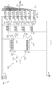
- Figure 1 is a schematic diagram of a beam steering device according to an embodiment of the present application.
- the beam steering device 100 includes a laser source 102 coupled to an optical phased array (OPA) 104.
- OPA optical phased array
- the OPA 104 may be formed on a silicon based platform such as silicon nitride using silicon photonics technology known in the art.
- the laser source 102 may be coupled to the OPA 104 via an optical fiber or may be included in the OPA 104.
- the OPA 104 comprises a beam splitter network 103 configured to split the laser beam generated by the laser source 102 into N outputs.
- the N outputs may be coupled to an antenna 105 configured to couple and emit the each of N outputs into free space forming an optical output beam 126.
- the OPA 104 will be described in more detail in Figures 2A-2B as well as Figures 3A-3B below. As described hereinbelow, the OPA 104 may be configured to electronically steer the beam over a wider angle to obtain improved coverage area.
- Figures 2A-2B are schematic diagrams of embodiments of the optical phase array (OPA) 104 configured to steer an output optical beam with improved coverage.
- OPA optical phase array
- Figures 2A-2B illustrate schematic diagrams of an optical phased array of a beam steering device configured to steer a beam around a central beam axis
- Figure 2A illustrates a schematic diagram of the optical phased array when it is configured to steer an output optical beam in a first direction
- Figure 2B illustrates a schematic diagram of the optical phased array when it is configured to steer the output optical beam in a second direction opposite the first direction.
- the plurality of N outputs of the beam splitter network 103 are generated around a central beam axis 127.
- the beam splitter network 103 comprises a plurality of stages of optical beam splitters 114.
- the optical beam splitters 114 may comprise 1 ⁇ 2 Y-junction tree or multimode interference (MMI) optical splitters.
- MMI multimode interference
- each stage of the beam splitter network 103 may comprise 2 i-1 optical beam splitters 114.
- Each of the optical beam splitters 114 of Figure 2A includes an input 118, a first output waveguide 120, and a second output waveguide 122.
- the first output waveguides 120 and the second output waveguides 122 of the final stage of the beam splitter network 103 are each coupled to an antenna 105.
- the antenna 105 may be an array antenna.
- the antenna 105 comprises arrays of gratings 107.
- the arrays of gratings 107 may comprise linear gratings. The length of each the linear gratings may be equal.
- the N outputs of the beam splitter network 103 may each be further coupled to an array of gratings 107.
- the optical phased array (OPA) 104 includes a first network of first phase shifters 110 configured to steer the output optical beam 126 in a first direction away from a longitude direction 128 and a second network of second phase shifters 112 configured to steer the output optical beam 126 in a second direction away from the longitude direction 128 opposite to the first direction.
- the first network of first phase shifters 110 is coupled to a first driver 106.
- the second network of second phase shifters 112 is coupled to a second driver 108.
- the first phase shifters 110 and the second phase shifters 112 are here connected to common reference potential such as a ground terminal 116.
- Each of the first output waveguides 120 of the beam splitter network 103 is associated to at least one first phase shifter 110.
- the first output waveguide 120 of each stage may be associated with a different quantity of first phase shifters 110.
- the quantity of first phase shifters 110 associated with the first output waveguides 120 on an i th stage of the beam splitter network 103 may be equal to N 2 i .
- each of the second output waveguides 122 of the beam splitter network 103 is associated to at least one second phase shifter 112.
- the quantity of second phase shifters 112 may be equal to the quantity of first phase shifters 110 in each stage of the beam splitter network 103.
- the second output waveguide 122 of an optical beam splitter 114 in a first stage may be associated to four second phase shifters 112
- the second output waveguide 122 of each optical beam splitter 114 in a second stage may be associated to two second phase shifters 112
- a second output waveguide 122 of each optical beam splitter 114 in a third stage may be associated to one second phase shifter 112.
- the first phase shifters 110 and the second phase shifters 112 may be identical.
- the first phase shifters 110 and the second phase shifters 112 may comprise thermal or electro-optical phase shifters.
- phase shifter 110 may be provided for each phase shifter 110, 112 or other combinations may be considered, if desired.
- the optical phased array (OPA) 104 may be configured to steer the output optical beam 126 in opposite directions away from the longitude direction 128.
- the output optical beam 126 may have a phase front 125.
- the first direction may be defined as either a positive beam steering angle ⁇ or a negative beam steering angle - ⁇ measured with respect to the central beam axis 127.
- the second direction may be defined as a beam steering angle with the opposite sign.
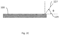
- the central beam axis 127 may be located along an axis that may be at an angle to the beam steering device 100 (See Figure 2C ).
- the first network of first phase shifters 110 may be configured to steer the output optical beam 126 in a first direction - ⁇ away from the longitude direction 128.
- the output optical beam 126 may be steered in the first direction - ⁇ by activating the first driver 106.
- the first driver 106 may apply a first potential to each of the first phase shifters 110.
- the first potential may configure the first phase shifters 110 to add a first phase offset to each optical beam passing through the first output waveguides 120.
- Each of the first phase shifters 110 that an optical beam passes through may add a phase shift of ⁇ .
- the first driver 106 is activated, and the second driver 108 is idle, the first phase offset added to each beam traveling through the first output waveguides 120 may equal N 2 i ⁇ ⁇ .
- Each of the beams traveling through the second output waveguides 122 may not undergo a phase shift. This may result in a constant phase difference equal to - ⁇ between adjacent N outputs along the longitude direction 128 (or vice versa).
- the laser beam generated from the laser source 102 may be split by an optical beam splitter 114 into a first beam B1 traveling along a first path through the first output waveguide 120 and a second beam B2 traveling along a second path through the second output waveguide 122.
- a first phase offset may not be added to the second beam B2 because it does not pass through any first phase shifters 110.
- a first phase offset equal to ⁇ may be added to the first beam B1 by each of the four first phase shifters 110 it passes through so that the total phase offset is equal to 4 ⁇ ⁇ .
- a first further optical beam splitter 114 may be configured to split the first beam B1 into a third beam B3 traveling along a third path and a fourth beam B4 traveling along a fourth path, and a second further optical beam splitter 114 may be configured to split the second beam B2 into a fifth beam B5 traveling along a fifth path and a sixth beam B6 traveling along a sixth path.
- the third beam B3 and the fifth beam B5 may each travel through a first output waveguide 120 of the two further optical beam splitters 114, while the second beam B2 and fourth beam B4 may each travel through a second output waveguide 122 of the two further optical beam splitters 114.
- the third beam B3 and the fifth beam B5 each pass through two first phase shifters 110 while the fourth beam B4 and sixth beam B6 do not.
- An additional first phase offset of 2 ⁇ ⁇ may be added to both the third beam B3 and fifth beam B5 from the two first phase shifters 110 they both pass through.
- An additional first phase offset may not be added to the fourth beam B4 and sixth beam B6 because they do not pass through any first phase shifters 110. Therefore, a first phase offset equal to 6 ⁇ ⁇ may be added to the third beam B3, a first phase offset equal to 4 ⁇ ⁇ may be added to the fourth beam B4, a first phase offset equal to 2 ⁇ ⁇ may be added to the fifth beam B5, and a first phase offset may not be added to the sixth beam B6.
- additional optical beam splitters 114 may split a respective beam into two outputs.
- the index of each of the N outputs may be defined as n and range from 1 to N along the longitude direction 128.
- the third through sixth beams may each be split into two outputs by each of the four optical beam splitters 114, resulting in eight outputs.
- the third beam B3 may be split into a first output O1 (e.g.
- the fourth beam B4 may be split into a third output O3 and a fourth output O4
- the fifth beam B5 may be split into a fifth output O5 and a sixth output O6
- the sixth beam B6 may be split into a seventh output O7 and an eighth output O8.
- each first output waveguide 120 of each optical beam splitter 114 of the third (and final) stage will pass through one first phase shifter 110 while the other beams do not.
- an additional first phase offset equal to ⁇ may be added to the beams traveling through each of the first output waveguides 120.
- the N outputs with odd n values i.e. first, third, fifth, and seventh
- the N outputs with even n values i.e. second, fourth, sixth, eighth
- the beam corresponding to the first output O1 may have a first phase offset equal to 7 ⁇ ⁇
- the beam corresponding to the second output O2 may have a first phase offset equal 6 ⁇ ⁇
- the beam corresponding to the third output O3 may have a first phase offset equal to 5 ⁇ ⁇
- the beam corresponding to the fourth output O4 may have a first phase offset equal to 4 ⁇ ⁇
- the beam corresponding to the fifth output O5 may have a first phase offset equal to 3 ⁇ ⁇
- the beam corresponding to the sixth output O6 may have a first phase offset equal to 2 ⁇ ⁇
- the beam corresponding to the seventh output O7 may have a first phase offset equal to ⁇
- a first phase offset may not be added to the beam corresponding to the eighth output.
- the first phase offset added to each of the N outputs may be equal to (N-n) ⁇ .
- the first phase offset added to each of the N outputs may range from (N-n) ⁇ to o with a constant phase difference along the longitude direction 128, regardless of the value of N. This may result in a negative constant phase difference - ⁇ between N outputs along longitude direction 128. Therefore, the first phase shifters 110 may steer the output optical beam 126 in the first direction - ⁇ (or vice versa).
- the first phase shifters 110 may configure a phase difference with either a positive sign or a negative sign based on the first potential so as to result in a positive or negative beam direction with respect to the longitude direction 128.
- the first network of first phase shifters 110 may be configured to only steer the output optical beam 126 with only either a positive beam steering angle ⁇ or a negative beam steering angle - ⁇ .
- the second network of second phase shifters 112 may be configured to provide a phase shift with the opposite sign.
- One advantage of this is that it allows for the output optical beam 126 to be steered in both directions of the central beam axis 127. In other words, the range of the beam steering angle may be doubled.
- the first driver 106 may be deactivated, and the second driver 108 may be activated.
- the second driver 108 may transmit a second potential to each of the second phase shifters 112.
- the second potential may be the same as the first potential.
- the second potential may configure the second phase shifters 112 to steer the output optical beam 126 in a second direction ⁇ .
- the second direction may be defined as a positive beam steering angle ⁇ or a negative beam steering angle - ⁇ so long as it is opposite the first direction.
- the second potential may configure the second phase shifters 112 to add a second phase offset to each optical beam passing through the second output waveguides 122.
- the second phase offset may be different than the first phase offset.
- the added second phase offset may be opposite to the first phase offset.
- the phase difference between N outputs along the longitude direction 128 provided by the first phase shifters 110 and the second phase shifters 112 may have opposite signs.
- the second phase difference added to each of the N outputs may be equal to (n-1) ⁇ . This will be discussed in more detail below.
- a second phase offset equal to 4 ⁇ ⁇ may only be added to the second beam B2 due to each of the four second phase shifters 112 it passes through.
- a second phase offset of 2 ⁇ ⁇ may only be added to the fourth beam B4 and sixth beam B6 due to the two second phase shifters 112 they both pass through.
- a second phase offset of ⁇ may only be added to N outputs with even indices (i.e. second, fourth, sixth, and eighth) due to the one second phase shifter 112 they pass through.
- a second phase offset may not be added to the beam corresponding to the first output O1
- the beam corresponding to the second output O2 may have a second phase offset equal to ⁇
- the beam corresponding to the third output O3 may have a second phase offset equal to 2 ⁇ ⁇
- the beam corresponding to the fourth output O4 may have a second phase offset equal to 3 ⁇ ⁇
- the beam corresponding to the fifth output O5 may have a second phase offset equal to 4 ⁇ ⁇
- the beam corresponding to the sixth output O6 may have a second phase offset equal to 5 ⁇ ⁇
- the beam corresponding to the seventh output O7 may have a second phase offset equal to 6 ⁇ ⁇
- the beam corresponding to the eighth output O8 may have a second phase offset equal to 7 ⁇ ⁇ .
- this may allow the output optical beam 126 to be steered in a second direction ⁇ away from the longitude direction 128.
- One advantage of this is that it doubles the range of the beam steering angle.
- an optical phased array (OPA) 104 may be configured to have a central beam axis 127 disposed at a fixed offset angle.
- OPA optical phased array
- Figure 2C illustrates a side view of the beam steering device.
- Figure 2C functions to provide an understanding of how the central beam axis 127 is located away from a device axis 129 perpendicular to the beam steering device 100.
- the output optical beam 126 and the central beam axis 127 may be formed in the half-space above the device 100.
- the central beam axis 127 may be disposed at an emission angle ⁇ measured with respect to the device axis 129.This is because light emission from the antenna is at an angle to the surface of the device 100 referred herein as the emission angle ⁇ .
- Figures 3A-3B illustrate schematic diagrams of an optical phased array of a beam steering device, where Figure 3A illustrates a schematic diagram of an optical phased configured to have a central beam axis disposed at an offset angle in a first direction, and Figure 3B illustrates a schematic diagram of an optical phased configured to have a central beam axis disposed at an offset angle in a second direction.
- the central beam axis is offset at an angle to the main axis.
- the beam angle is not symmetric with the main axis.
- these OPAs enable a larger spread in beam angle in the beam steering device.
- a positive offset angle OPA 204A may be further configured to have a central beam axis 127 disposed in a first direction away from a main axis 130 perpendicular to the antenna 105.
- the first direction may be defined as an offset angle ⁇ between the central beam axis 127 and the main axis 130 perpendicular to the antenna 105.
- a central beam axis 127 disposed in the first direction may be defined as a central beam axis 127 with a positive fixed offset angle ⁇ (or vice versa).
- the antenna 105 further includes N linear waveguides 134 and a plurality of N fixed phase shifters 132.
- the plurality of N fixed phase shifters 132 are coupled between the beam splitter network 103 and the N linear waveguides 134.
- the inputs of N fixed phase shifters 132 are coupled to the N outputs of the beam splitter network 103 and the outputs of the N fixed phase shifters 132 are coupled to the inputs of each of the N linear waveguides 134.
- the N fixed phase shifters 132 may have different optical path lengths.
- the difference of the optical path length between couples of the N fixed phase shifters 132 may be equal.
- the optical path length of the N fixed phase shifters 132 may decrease along the longitude direction 128 to form a fixed offset angle ⁇ in the first direction.
- the direction of the fixed offset angle ⁇ will be in the direction of increasing optical path lengths.
- the longer the optical path length of the N fixed phase shifters 132 the greater the magnitude of the fixed offset angle ⁇ . Therefore, the magnitude and direction of the fixed offset angle ⁇ may be configured based on the optical path lengths of each of the N fixed phase shifters 132.
- each of the N fixed phase shifters 132 may comprise N curved waveguides with different curvatures. As understood by those with ordinary skill in the art, the greater the curvature, the longer the optical path length (or vice versa). Therefore, the decrease in optical path lengths may be realized by decreasing the curvature of the N fixed phase shifters 132 along the longitude direction 128.
- a negative offset angle OPA 204B may be further configured to have a central beam axis 127 disposed in a second direction away from the main axis 130.
- the second direction may be opposite the first direction.
- the second direction may be defined as a negative fixed offset angle - ⁇ (or vice versa), so long as it is opposite the first direction.
- the magnitude and sign of the second direction may depend on the difference in optical path length of the N fixed phase shifters 132. Therefore, the central beam axis 127 may be disposed in with a negative fixed offset angle - ⁇ by increasing the optical path length (or curvature) of each of the N fixed phase shifters 132 along the longitude direction 128.
- Figure 4 illustrates a process flow of steering an output optical beam with improved coverage.
- a laser source 102 is coupled to optical phased array (OPA) 104 (or 204A, 204B).
- OPA optical phased array
- the OPA 104 (or 204A, 204B) comprises beam splitter network 103 comprising the plurality of N outputs around central beam axis 127, the first network of first phase shifters 110, and the second network of second phase shifters 112.
- the OPA 104 (or 204A, 204B) may have any of the configurations disclosed in Figures 2A-2B and Figures 3A-3B .
- the output optical beam 126 is generated around the central beam axis 127 at the output of the beam splitter network 103.
- the output optical beam 126 may be formed around the central beam axis by being steered in a first direction - ⁇ and a second direction ⁇ (or vice versa).
- the output optical beam 126 may be steered in the first direction by applying a first potential to each of the first phase shifters 110 with the first driver 106.
- the first direction may be a positive beam steering angle ⁇ or a negative beam steering angle - ⁇ .
- the output optical beam 126 may be steered in the first direction in the same manner described in Figure 2A .
- the output optical beam 126 may be steered in a second direction away from the central beam axis 127.
- the output optical beam 126 may be steered in the second direction by deactivating the first driver 106 and supplying a second potential to each of the second phase shifters 112 using the second driver 108.
- the second direction may be defined as a beam steering angle with an opposite sign of the first direction.
- the output optical beam 126 may be steered in the first direction in the same manner described in Figure 2B .
- the beam steering device may comprise a plurality of optical phased arrays (OPAs) to increase the range of coverage of a beam steering device without requiring additional circuitry.
- OPAs optical phased arrays
- Figures 5A-5B illustrate schematic diagrams of a beam steering device comprising a plurality of optical phased arrays (OPAs), where Figure 5A illustrates a beam steering device with an even number of optical phased arrays (OPAs), and Figure 5B illustrates a beam steering device with an odd number of optical phased arrays (OPAs).
- OPAs optical phased arrays
- an optical beam steering device 500 comprises laser source 102 coupled to the input of a switching matrix 502.
- the switching matrix 502 comprises a plurality of z outputs that are coupled to a plurality of OPAs 503.
- the switching matrix 502 may be configured to sequentially guide a laser beam emitted by the laser source 102 around a main axis 530 to each of the plurality of OPAs 503.
- the central beam axis 127 of each of the plurality of OPAs 503 may be different. This will be explained in more detail below.
- the central beam axis 127 of each of the plurality of OPAs 503 may be configured to be disposed around the main axis 530. In other words, the central beam axis 127 of each of the plurality of OPAs 503 may be configured to be disposed with a different fixed offset angle ⁇ .
- the magnitude of the fixed offset angle ⁇ of each central beam axis 127 may be configured to increase away from the main axis 530.
- the plurality of OPAs 503 may include a first set of OPAs 508 and a second set of OPAs 510.
- the first set of OPAs 508 may include each of the OPAs positioned above the main axis 530.
- the second set of OPAs 510 may comprise each of the OPAs positioned below the main axis 530.
- the first set of OPAs 508 and the second set of OPAs 510 may comprise the same quantity of OPAs.
- the first set of OPAs 508 may each have a central beam axis 127 configured to have positive fixed offset angles ⁇ increasing in magnitude away from the main axis 530 (similar to the OPA described with respect to Figure 3A ).
- the second set of OPAs 510 may each have a central beam axis 127 configured to have negative fixed offset angles - ⁇ increasing in magnitude away from the main axis 530 (or vice versa).
- the OPAs in the first set of OPAs 508 may include N fixed phase shifters 132 with decreasing optical path lengths along the longitude direction 128.
- the OPAs in the second set of OPAs 510 may include N fixed phase shifters 132 with increasing optical path lengths along the longitude direction 128.
- the longest fixed phase shifter of an OPA in the first set of OPAs 508 that is closer to the main axis 530 will be shorter than the shortest fixed phase shifter in an OPA in the first set of OPAs 508 further away from the main axis 530.
- the optical path length of each of the N fixed phase shifters 132 of an OPA in the first set of OPAs 508 and an OPA in the second set of OPAs 510 that are equidistant from the main axis 530 may be equal. Therefore, the magnitude of fixed offset angles ⁇ of OPAs that are equidistant from the main axis 530 may be equal.
- this allows for the central beam axis 127 of each of the plurality of OPA's 503 to increase away from the main axis 530.
- the switching matrix 502 may be used to steer the direction of the output of the optical beam steering device 500 by sequentially switching between the plurality of OPAs 503.
- Figure 5B illustrates an alternative beam steering device, which works without having any possible central blindness. While the beam steering device described in Figure 5A is optimized to steer the beam over a wider angle, the device may not be effective in analyzing objects that are located in the main axis of the device. To offset any such deficiencies, the beam steering device of Figure 5B includes an additional OPA that is centrally located.
- the first set of OPAs 508 and the second set of OPAs 510 may be separated by a central OPA 504 and positioned along the main axis 530.
- the central OPA 504 positioned along the main axis 530 may be configured to have a central beam axis 127 formed along the main axis 530. Therefore, the central beam axis 127 of the central OPA 504 does not have a fixed offset angle and therefore the central OPA 504 is similar to the OPA 104 described in Figures 2A-2B .
- Figure 6 illustrates a process flow of controlling a beam steering device including a plurality of optical phased arrays (OPAs).
- OPAs optical phased arrays
- a plurality of outputs of a switching matrix 502 may be coupled between laser source 102 and a plurality of optical phased arrays (OPAs) 503.
- OPAs optical phased arrays
- Each of the plurality of OPAs 503 may be configured to have an optical output direction around a main axis 530.
- each of the plurality of OPAs 303 may be configured to generate an output optical beam 126 around a different central beam axis 127.
- the central beam axis 127 of each of the plurality OPAs 503 may be disposed around the main axis 530.
- Each central beam axis 127 may be disposed around the main axis 530 in the same manner discussed in Figures 5A-5B .
- the switching matrix 502 may be used to sequentially switch between the plurality of OPAs 503 to steer the direction of the optical output from the plurality of OPAs 503. As described above, this allows for an optical beam steering device 500 with an improved coverage without requiring additional circuitry.
- An optical beam steering device including: a laser source coupled to an optical phased array (OPA), the OPA including: a beam splitter network optically coupled to the laser source and configured to split a laser beam generated by the laser source into N outputs to generate an output optical beam; a first network of first phase shifters configured to steer the output optical beam in a first direction away from a longitude direction; and a second network of second phase shifters configured to steer the output optical beam in a second direction away from the longitude direction, the second direction being opposite to the first direction.
- OPA optical phased array
- Example 2 The optical beam steering device of example 1, where the beam splitter network includes a plurality of stages of optical beam splitters, each optical beam splitter having an input, a first output waveguide, and a second output waveguide, each first output waveguide of the optical beam splitter being associated with one of the first phase shifters and each second output waveguide of the optical beam splitter being associated with one of the second phase shifters, the first phase shifters being configured to add a first phase offset to an optical beam passing through the first output waveguide, the second phase shifters being configured to add a second phase offset to an optical beam passing through the second output waveguide.
- Example 3 The optical beam steering device of one of examples 1 or 2, where the first output waveguide and the second output waveguide of a final stage of each of the plurality of stages of optical beam splitters are each connected to an array of linear gratings.
- Example 4 The optical beam steering device of one of examples 1 to 3, where an i th stage of the plurality of stages of optical beam splitters includes: 2i-1 1 ⁇ 2 optical splitters, and where i is an integer greater than or equal to 1.
- Example 5 The optical beam steering device of one of examples 1 to 4, where the first network of first phase shifters includes: a first driver coupled to each of the first phase shifters, the first driver configured to configure the first phase shifters to provide a first phase offset.
- Example 6 The optical beam steering device of one of examples 1 to 5, where the second network of second phase shifters includes: a second driver coupled to each of the second phase shifters, the second driver being configured to configure the second phase shifters to provide a second phase offset different from the first phase offset.
- Example 7 The optical beam steering device of one of examples 1 to 6, where the first phase shifters and the second phase shifters are identical.
- Example 8 The optical beam steering device of one of examples 1 to 7, where first phase offset is opposite to the second phase offset.
- Example 9 The optical beam steering device of one of examples 1 to 8, where the first network of first phase shifters and the second network of second phase shifters include thermal or electro-optical phase shifters.
- Example 10 The optical beam steering device of one of examples 1 to 9, further including: an antenna including N linear waveguides, the N linear waveguides corresponding to the N outputs; and N fixed phase shifters coupled to the beam splitter network, each of the N fixed phase shifters having a different optical path length than another one of the N fixed phase shifters, and each of the N linear waveguides being coupled to an output of one of the N fixed phase shifters.
- Example 11 The optical beam steering device of one of examples 1 to 10, further including a switching matrix coupled between the laser source and the OPA.
- An optical beam steering device including: a switching matrix including a plurality of z outputs coupled to a plurality of optical phased arrays (OPAs) and configured to guide a laser beam emitted by a laser source sequentially to the plurality of OPAs, the laser being emitted around a main axis, each of the plurality of OPAs including an output optical beam direction oriented around a central beam axis, the central beam axis of each of the plurality of OPAs being different from one another, each of the plurality of OPAs including: a beam splitter network coupled to the laser source configured to split the laser beam into N outputs to generate a corresponding output optical beam, a first network of first phase shifters configured to steer the output optical beam in a first direction away from the central beam axis, and a second network of second phase shifters configured to steer the output optical beam in a second direction away from the central beam axis, the second direction being opposite to the first direction.
- OPAs optical phased arrays
- Example 13 The optical beam steering device of example 12, where the beam splitter network includes a plurality of stages of optical beam splitters, each optical beam splitter having an input, a first output waveguide, and a second output waveguide, each first output waveguide of the optical beam splitter being associated with one of the first phase shifters and each second output waveguide of the optical beam splitter being associated with one of the second phase shifters, the first phase shifters being configured to add a first phase offset to an optical beam passing through the first output waveguide, the second phase shifters being configured to add a second phase offset to an optical beam passing through the second output waveguide.
- Example 14 The optical beam steering device of one of examples 12 or 13, where an i th stage of the plurality of stages of optical beam splitters includes 2i-1 1 ⁇ 2 optical splitters.
- Example 15 The optical beam steering device of one of examples 12 to 14, where the first network of first phase shifters includes: a first driver coupled to each of the first phase shifters, the first driver configured to configure the first phase shifters to provide a first phase offset.
- Example 16 The optical beam steering device of one of examples 12 to 15, where the second network of second phase shifters includes: a second driver coupled to each of the second phase shifters, the second driver being configured to configure the second phase shifters to provide a second phase offset different from the first phase offset.
- Example 17 The optical beam steering device of one of examples 12 to 16, where a first one of the plurality of OPAs include: an antenna including N linear waveguides corresponding to the N outputs of the first one of the plurality of OPAs; and N fixed phase shifters coupled to the beam splitter network, each of the N fixed phase shifters having a different optical path length than another one of the N fixed phase shifters, and each of the N linear waveguides being coupled to an output of one of the N fixed phase shifters.
- Example 18 The optical beam steering device of one of examples 12 to 17, where each of the N fixed phase shifters include curved waveguides, where a curvature of the each of the N fixed phase shifters is different from another one of the N fixed phase shifters.
- Example 19 The optical beam steering device of one of examples 12 to 18, where the central beam axis of the plurality of OPAs is disposed around the main axis, where the optical path length of each of the N fixed phase shifters increases away from the main axis of the optical beam steering device.
- Example 20 The optical beam steering device of one of examples 12 to 19, where the central beam axis of a second one of the plurality of OPAs is oriented along the main axis.
- Example 21 A method for beam steering, the method including: coupling a laser source to a first optical phased array (OPA), the first OPA including a beam splitter network having an output including a plurality of N outputs around a first central beam axis, a first network of first phase shifters, and a second network of second phase shifters; generating an output optical beam around the first central beam axis at the output of the beam splitter network by steering the output optical beam in a first direction away from the first central beam axis with a first network of first phase shifters; and steering the output optical beam in a second direction away from the first central beam axis with a second network of second phase shifters, the second direction being opposite to the first direction.
- OPA optical phased array
- Example 22 The method of example 21, where the beam splitter network includes a plurality of stages of optical beam splitters, each optical beam splitter having an input, a first output waveguide, and a second output waveguide, each first output waveguide of the optical beam splitter being associated with one of the first phase shifters and each second output waveguide of the optical beam splitter being associated with one of the second phase shifters, and where generating the output optical beam includes: applying a first potential to the first phase shifters with a first driver to add a first phase offset to an optical beam passing through the first output waveguide; and applying a second potential to the second phase shifters with a second driver to add a second phase offset to an optical beam passing through the second output waveguide.
- Example 23 The method of one of examples 21 or 22, further including coupling a plurality of outputs of a switching matrix between the laser source and a plurality of optical phased arrays (OPAs) including the first OPA, the plurality of OPAs being arranged to have an optical output direction around a main axis, each of the plurality of OPAs including an output optical beam direction oriented around a central beam axis, the central beam axis of each of the plurality of OPAs being different from one another.
- OPAs optical phased arrays
- Example 24 The method of one of examples 21 to 23, further including: sequentially switching between the plurality of OPAs to steer the beam direction of the output from the plurality of OPAs.
Landscapes
- Physics & Mathematics (AREA)
- General Physics & Mathematics (AREA)
- Nonlinear Science (AREA)
- Engineering & Computer Science (AREA)
- Optics & Photonics (AREA)
- Computer Networks & Wireless Communication (AREA)
- Radar, Positioning & Navigation (AREA)
- Remote Sensing (AREA)
- Electromagnetism (AREA)
- Variable-Direction Aerials And Aerial Arrays (AREA)
Abstract
Description
- The present invention relates generally to optical beam steering, and, in particular, to a phase shifter architecture for optical beam steering devices.
- The use of devices utilizing free-space laser beams have been proven for numerous applications in three-dimensional mapping and imaging, such as geological surveying, and control and navigation for autonomous vehicles. Light detection and ranging (LiDAR) has emerged as a technology for determining a variable distance of an object by transmitting a beam towards an object and measuring the time for light reflected off the object to return. In this context, the light beam has to be transmitted towards the object. To be able to map a target area around the sensor, the sensor's beam has to be oriented or steered in different directions.
- Of course, mechanically moving the sensor is one way to achieve beam steering. One way to steer the beam of a LiDAR sensor without mechanical movement of the sensor is an Optical Phased Array (OPA). OPAs provide a more flexible and efficient beam steering device.
- OPAs are designed to generate beams with different phase shifts so as to create patterns of constructive and destructive interference forming an output beam. However, conventional OPAs are not scalable and complex in both the architecture as well as electrical control when a large number of outputs are to be realized.
- Thus, an aim of the present invention is to overcome the drawbacks of the prior art.
- According to the invention, a optical beam steering device and a method for beam steering are provided, as defined in the accompanying claims.
- For a more complete understanding of the present invention, and the advantages thereof, reference is now made to the following descriptions taken in conjunction with the accompanying drawings, in which:
-
Figure 1 illustrates a schematic diagram of a beam steering device; -
Figures 2A-2C illustrate schematic diagrams of an optical phased array of a beam steering device configured to steer a beam around a central beam axis, whereFigure 2A illustrates a schematic diagram of the optical phased array when it is configured to steer an output optical beam in a first direction,Figure 2B illustrates a schematic diagram of the optical phased array when it is configured to steer the output optical beam in a second direction opposite the first direction, andFigure 2C illustrates a side view of the beam steering device; -
Figures 3A-3B illustrate schematic diagrams of an optical phased array of a beam steering device, whereFigure 3A illustrates a schematic diagram of an optical phased configured to have a central beam axis disposed at an offset angle in a first direction, andFigure 3B illustrates a schematic diagram of an optical phased configured to have a central beam axis disposed at an offset angle in a second direction; -
Figure 4 illustrates a process flow of steering an output optical beam with improved coverage. -
Figures 5A-5B illustrate schematic diagrams of a beam steering device comprising a plurality of optical phased arrays (OPAs), whereFigure 5A illustrates a beam steering device with an even number of optical phased arrays (OPAs), andFigure 5B illustrates a beam steering device with an odd number of optical phased arrays (OPAs); and -
Figure 6 illustrates a process flow of controlling a beam steering device including a plurality of optical phased arrays (OPAs). - OPAs (Optical Phased Arrays) operate by transmitting a plurality of beams through an array antenna that superimpose (i.e., combine) in the far-field to form an output beam. Each of the plurality of beams undergoes a different phase shift so each of the transmitted beams is emitted at different times. This may result in the output optical beam being transmitted at an angle, known as the beam steering angle. The coverage of the beam steering device may be defined by the range of the beam steering angle.
- OPAs typically comprise three elements: a beam splitting network to split the input of the OPA into a plurality of channels, a network of phase shifters configured to generate the phase difference between antenna elements, and the antenna elements.
- Typically, OPAs utilize a phase shifter on each of the channels, except one, to cause an equal phase difference (e.g. a different phase shift) between adjacent channels. However, to generate a different phase shift between adjacent channels, a different voltage signal must be applied to each of the individual phase shifters. This may require each of the phase shifters to be controlled by individual and connected electronic circuits.
- While optical phased arrays (OPAs) allow for non-mechanical beam steering of a LiDAR sensor, limitations still exist. As the quantity of channels increases, the number of individual and connected electronic circuits required to control the phase shift increases. Problematically, this results in an increase in power consumption and makes controlling the phase shift of each of the channels very difficult or even impossible.
- Hereinbelow, an optical transmitter such as an optical beam steering device is described, that can steer an output beam with an improved coverage without an increase in the difficulty of controlling the phase shift of the channels. More specifically, a beam steering device is described, that has an increased beam steering angle range and does not require additional circuitry as the quantity of channels in the OPA increases.
-
Figure 1 is a schematic diagram of a beam steering device according to an embodiment of the present application. - Referring to
Figure 1 , thebeam steering device 100 includes alaser source 102 coupled to an optical phased array (OPA) 104. - The OPA 104 may be formed on a silicon based platform such as silicon nitride using silicon photonics technology known in the art. The
laser source 102 may be coupled to the OPA 104 via an optical fiber or may be included in the OPA 104. - The OPA 104 comprises a
beam splitter network 103 configured to split the laser beam generated by thelaser source 102 into N outputs. - The N outputs may be coupled to an
antenna 105 configured to couple and emit the each of N outputs into free space forming anoptical output beam 126. - The OPA 104 will be described in more detail in
Figures 2A-2B as well asFigures 3A-3B below. As described hereinbelow, the OPA 104 may be configured to electronically steer the beam over a wider angle to obtain improved coverage area. -
Figures 2A-2B are schematic diagrams of embodiments of the optical phase array (OPA) 104 configured to steer an output optical beam with improved coverage. -
Figures 2A-2B illustrate schematic diagrams of an optical phased array of a beam steering device configured to steer a beam around a central beam axis, whereFigure 2A illustrates a schematic diagram of the optical phased array when it is configured to steer an output optical beam in a first direction, andFigure 2B illustrates a schematic diagram of the optical phased array when it is configured to steer the output optical beam in a second direction opposite the first direction. - In
Figure 2A , the plurality of N outputs of thebeam splitter network 103 are generated around acentral beam axis 127. - In
figure 2A , thebeam splitter network 103 comprises a plurality of stages ofoptical beam splitters 114. Theoptical beam splitters 114 may comprise 1×2 Y-junction tree or multimode interference (MMI) optical splitters. - The
beam splitter network 103 comprises i stages ofoptical beam splitters 114, where i is an integer greater than or equal to 1. The value of i may be determined based on the desired value of N outputs using the formula, N = 2 i . For example, as illustrated inFigure 2A , an eight outputbeam splitter network 103 may require three stages of optical beam splitters 114 (i.e., 8 = 23). AlthoughFigure 2A illustrates anOPA 104 with eight outputs, the OPA 104 may support any suitable quantity of outputs. - The quantity of
optical beam splitters 114 may increase between each progressive stage. For instance, each stage of thebeam splitter network 103 may comprise 2i-1optical beam splitters 114. For example, a first stage of the beam splitter network 103 (i.e., i=i) may include oneoptical beam splitter 114, a second stage of the beam splitter network 103 (i.e. i=2) may include twooptical beam splitters 114, and the third stage of the beam splitter network 103 (i.e. i=3) may include fouroptical beam splitters 114. - Each of the
optical beam splitters 114 ofFigure 2A includes aninput 118, afirst output waveguide 120, and asecond output waveguide 122. - In
figure 2A , thefirst output waveguides 120 and thesecond output waveguides 122 of the final stage of thebeam splitter network 103 are each coupled to anantenna 105. Theantenna 105 may be an array antenna. Infigure 2A , theantenna 105 comprises arrays ofgratings 107. The arrays ofgratings 107 may comprise linear gratings. The length of each the linear gratings may be equal. In other words, the N outputs of thebeam splitter network 103 may each be further coupled to an array ofgratings 107. - The optical phased array (OPA) 104 includes a first network of
first phase shifters 110 configured to steer the outputoptical beam 126 in a first direction away from alongitude direction 128 and a second network ofsecond phase shifters 112 configured to steer the outputoptical beam 126 in a second direction away from thelongitude direction 128 opposite to the first direction. - In
figure 2A , the first network offirst phase shifters 110 is coupled to afirst driver 106. The second network ofsecond phase shifters 112 is coupled to asecond driver 108. Thefirst phase shifters 110 and thesecond phase shifters 112 are here connected to common reference potential such as aground terminal 116. - Each of the
first output waveguides 120 of thebeam splitter network 103 is associated to at least onefirst phase shifter 110. Thefirst output waveguide 120 of each stage may be associated with a different quantity offirst phase shifters 110. The quantity offirst phase shifters 110 associated with thefirst output waveguides 120 on an ith stage of thebeam splitter network 103 may be equal to
Figure 2A , thefirst output waveguide 120 of anoptical beam splitter 114 in a first stage (i.e. i=i) maybe associated to fourfirst phase shifters 110, thefirst output waveguide 120 of eachoptical beam splitter 114 in a second stage (i.e. i=2) may be associated to twofirst phase shifters 110, and thefirst output waveguide 120 of eachoptical beam splitter 114 in a third stage (i.e. i=3) may be associated to onefirst phase shifter 110. - Similarly, each of the
second output waveguides 122 of thebeam splitter network 103 is associated to at least onesecond phase shifter 112. The quantity ofsecond phase shifters 112 may be equal to the quantity offirst phase shifters 110 in each stage of thebeam splitter network 103. - For example, as illustrated in
Figure 2A , thesecond output waveguide 122 of anoptical beam splitter 114 in a first stage (i.e. i=i) may be associated to foursecond phase shifters 112, thesecond output waveguide 122 of eachoptical beam splitter 114 in a second stage (i.e. i=2) may be associated to twosecond phase shifters 112, and asecond output waveguide 122 of eachoptical beam splitter 114 in a third stage (i.e. i=3) may be associated to onesecond phase shifter 112. Thefirst phase shifters 110 and thesecond phase shifters 112 may be identical. Thefirst phase shifters 110 and thesecond phase shifters 112 may comprise thermal or electro-optical phase shifters. - Advantageously, coupling both of the networks of phase shifters to a single respective driver allows the quantity of N outputs to be increased without requiring additional drivers. However, a driver may be provided for each
phase shifter - As described above, the optical phased array (OPA) 104 may be configured to steer the output
optical beam 126 in opposite directions away from thelongitude direction 128. As understood by those with ordinary skill in the art, the outputoptical beam 126 may have aphase front 125. The first direction may be defined as either a positive beam steering angle θ or a negative beam steering angle -θ measured with respect to thecentral beam axis 127. The second direction may be defined as a beam steering angle with the opposite sign. Thecentral beam axis 127 may be located along an axis that may be at an angle to the beam steering device 100 (SeeFigure 2C ). - In the example of
Figure 2A , the first network offirst phase shifters 110 may be configured to steer the outputoptical beam 126 in a first direction -θ away from thelongitude direction 128. - The output
optical beam 126 may be steered in the first direction -θ by activating thefirst driver 106. When activated, thefirst driver 106 may apply a first potential to each of thefirst phase shifters 110. The first potential may configure thefirst phase shifters 110 to add a first phase offset to each optical beam passing through thefirst output waveguides 120. Each of thefirst phase shifters 110 that an optical beam passes through may add a phase shift of δΦ. When thefirst driver 106 is activated, and thesecond driver 108 is idle, the first phase offset added to each beam traveling through thefirst output waveguides 120 may equal
second output waveguides 122 may not undergo a phase shift. This may result in a constant phase difference equal to -δΦ between adjacent N outputs along the longitude direction 128 (or vice versa). - For example, in a first stage of the
beam splitter network 103, the laser beam generated from thelaser source 102 may be split by anoptical beam splitter 114 into a first beam B1 traveling along a first path through thefirst output waveguide 120 and a second beam B2 traveling along a second path through thesecond output waveguide 122. A first phase offset may not be added to the second beam B2 because it does not pass through anyfirst phase shifters 110. A first phase offset equal to δΦ may be added to the first beam B1 by each of the fourfirst phase shifters 110 it passes through so that the total phase offset is equal to 4∗ δΦ. - In a second stage of the
beam splitter network 103, a first furtheroptical beam splitter 114 may be configured to split the first beam B1 into a third beam B3 traveling along a third path and a fourth beam B4 traveling along a fourth path, and a second furtheroptical beam splitter 114 may be configured to split the second beam B2 into a fifth beam B5 traveling along a fifth path and a sixth beam B6 traveling along a sixth path. - The third beam B3 and the fifth beam B5 may each travel through a
first output waveguide 120 of the two furtheroptical beam splitters 114, while the second beam B2 and fourth beam B4 may each travel through asecond output waveguide 122 of the two furtheroptical beam splitters 114. - The third beam B3 and the fifth beam B5 each pass through two
first phase shifters 110 while the fourth beam B4 and sixth beam B6 do not. An additional first phase offset of 2∗ δΦ may be added to both the third beam B3 and fifth beam B5 from the twofirst phase shifters 110 they both pass through. An additional first phase offset may not be added to the fourth beam B4 and sixth beam B6 because they do not pass through anyfirst phase shifters 110. Therefore, a first phase offset equal to 6∗ δΦ may be added to the third beam B3, a first phase offset equal to 4∗ δΦ may be added to the fourth beam B4, a first phase offset equal to 2∗ δΦ may be added to the fifth beam B5, and a first phase offset may not be added to the sixth beam B6. - At the final stage of the
beam splitter network 103 additionaloptical beam splitters 114 may split a respective beam into two outputs. The index of each of the N outputs may be defined as n and range from 1 to N along thelongitude direction 128. Referring back toFigure 2A , the third through sixth beams may each be split into two outputs by each of the fouroptical beam splitters 114, resulting in eight outputs. The third beam B3 may be split into a first output O1 (e.g. n=i) and a second output O2, the fourth beam B4 may be split into a third output O3 and a fourth output O4, the fifth beam B5 may be split into a fifth output O5 and a sixth output O6, and the sixth beam B6 may be split into a seventh output O7 and an eighth output O8. - In the same manner discussed above, the beams traveling through each
first output waveguide 120 of eachoptical beam splitter 114 of the third (and final) stage will pass through onefirst phase shifter 110 while the other beams do not. Thus, an additional first phase offset equal to δΦ may be added to the beams traveling through each of thefirst output waveguides 120. The N outputs with odd n values (i.e. first, third, fifth, and seventh) may pass through thefirst output waveguides 120 while the N outputs with even n values (i.e. second, fourth, sixth, eighth) may pass through thesecond output waveguides 122. Therefore, the beam corresponding to the first output O1 may have a first phase offset equal to 7∗δΦ, the beam corresponding to the second output O2 may have a first phase offset equal 6∗ δΦ, the beam corresponding to the third output O3 may have a first phase offset equal to 5∗ δΦ, the beam corresponding to the fourth output O4 may have a first phase offset equal to 4∗ δΦ, the beam corresponding to the fifth output O5 may have a first phase offset equal to 3∗ δΦ, the beam corresponding to the sixth output O6 may have a first phase offset equal to 2∗ δΦ, the beam corresponding to the seventh output O7 may have a first phase offset equal to δΦ, and a first phase offset may not be added to the beam corresponding to the eighth output. - Therefore, the first phase offset added to each of the N outputs may be equal to (N-n)δΦ. The first phase offset added to each of the N outputs may range from (N-n)δΦ to o with a constant phase difference along the
longitude direction 128, regardless of the value of N. This may result in a negative constant phase difference -δΦ between N outputs alonglongitude direction 128. Therefore, thefirst phase shifters 110 may steer the outputoptical beam 126 in the first direction -θ (or vice versa). - As understood by those with ordinary skill in the art, the
first phase shifters 110 may configure a phase difference with either a positive sign or a negative sign based on the first potential so as to result in a positive or negative beam direction with respect to thelongitude direction 128. In other words, the first network offirst phase shifters 110 may be configured to only steer the outputoptical beam 126 with only either a positive beam steering angle θ or a negative beam steering angle -θ. Advantageously, the second network ofsecond phase shifters 112 may be configured to provide a phase shift with the opposite sign. One advantage of this is that it allows for the outputoptical beam 126 to be steered in both directions of thecentral beam axis 127. In other words, the range of the beam steering angle may be doubled. - Referring to
Figure 2B , after steering the beam in the first direction -θ, thefirst driver 106 may be deactivated, and thesecond driver 108 may be activated. Thesecond driver 108 may transmit a second potential to each of the second phase shifters 112.The second potential may be the same as the first potential. - The second potential may configure the
second phase shifters 112 to steer the outputoptical beam 126 in a second direction θ. The second direction may be defined as a positive beam steering angle θ or a negative beam steering angle -θ so long as it is opposite the first direction. - The second potential may configure the
second phase shifters 112 to add a second phase offset to each optical beam passing through thesecond output waveguides 122. The second phase offset may be different than the first phase offset. For example, the added second phase offset may be opposite to the first phase offset. In other words, the phase difference between N outputs along thelongitude direction 128 provided by thefirst phase shifters 110 and thesecond phase shifters 112 may have opposite signs. The second phase difference added to each of the N outputs may be equal to (n-1)δΦ. This will be discussed in more detail below. - Continuing the example discussed in
Figure 2A above, in the first stage of the beam splitter network 103 a second phase offset equal to 4∗ δΦ may only be added to the second beam B2 due to each of the foursecond phase shifters 112 it passes through. - In the second stage of the beam splitter network, a second phase offset of 2∗ δΦ may only be added to the fourth beam B4 and sixth beam B6 due to the two
second phase shifters 112 they both pass through. - In the final stage of the beam splitter network, a second phase offset of δΦ may only be added to N outputs with even indices (i.e. second, fourth, sixth, and eighth) due to the one
second phase shifter 112 they pass through. - Therefore, a second phase offset may not be added to the beam corresponding to the first output O1, the beam corresponding to the second output O2 may have a second phase offset equal to δΦ, the beam corresponding to the third output O3 may have a second phase offset equal to 2∗δΦ, the beam corresponding to the fourth output O4 may have a second phase offset equal to 3∗δΦ, the beam corresponding to the fifth output O5 may have a second phase offset equal to 4∗δΦ, the beam corresponding to the sixth output O6 may have a second phase offset equal to 5∗δΦ, the beam corresponding to the seventh output O7 may have a second phase offset equal to 6∗δΦ, and the beam corresponding to the eighth output O8 may have a second phase offset equal to 7∗δΦ.
- Advantageously, this may allow the output
optical beam 126 to be steered in a second direction θ away from thelongitude direction 128. One advantage of this is that it doubles the range of the beam steering angle. - In some situations, an optical phased array (OPA) 104 may be configured to have a
central beam axis 127 disposed at a fixed offset angle. Advantageously, this allows for an output beam to be positioned and steered around acentral beam axis 127 pointing in different directions. -
Figure 2C illustrates a side view of the beam steering device.Figure 2C functions to provide an understanding of how thecentral beam axis 127 is located away from adevice axis 129 perpendicular to thebeam steering device 100. Referring toFigure 2C , as understood by those with ordinary skill in the art, the outputoptical beam 126 and thecentral beam axis 127 may be formed in the half-space above thedevice 100. In other words, thecentral beam axis 127 may be disposed at an emission angle Φ measured with respect to the device axis 129.This is because light emission from the antenna is at an angle to the surface of thedevice 100 referred herein as the emission angle Φ. -
Figures 3A-3B illustrate schematic diagrams of an optical phased array of a beam steering device, whereFigure 3A illustrates a schematic diagram of an optical phased configured to have a central beam axis disposed at an offset angle in a first direction, andFigure 3B illustrates a schematic diagram of an optical phased configured to have a central beam axis disposed at an offset angle in a second direction. - Unlike the prior embodiments in which the central beam axis was symmetrically located along the main axis, here, the central beam axis is offset at an angle to the main axis. In other words, the beam angle is not symmetric with the main axis. As will be described in
Figures 5A-5B , these OPAs enable a larger spread in beam angle in the beam steering device. - Referring to
Figure 3A , a positive offsetangle OPA 204A may be further configured to have acentral beam axis 127 disposed in a first direction away from amain axis 130 perpendicular to theantenna 105. The first direction may be defined as an offset angle Ψ between thecentral beam axis 127 and themain axis 130 perpendicular to theantenna 105. For example, acentral beam axis 127 disposed in the first direction may be defined as acentral beam axis 127 with a positive fixed offset angle Ψ (or vice versa). - Here, the
antenna 105 further includes Nlinear waveguides 134 and a plurality of N fixedphase shifters 132. The plurality of N fixedphase shifters 132 are coupled between thebeam splitter network 103 and the Nlinear waveguides 134. In other words, here the inputs of N fixedphase shifters 132 are coupled to the N outputs of thebeam splitter network 103 and the outputs of the N fixedphase shifters 132 are coupled to the inputs of each of the Nlinear waveguides 134. - The N fixed
phase shifters 132 may have different optical path lengths. The difference of the optical path length between couples of the N fixedphase shifters 132 may be equal. For example, the optical path length of the N fixedphase shifters 132 may decrease along thelongitude direction 128 to form a fixed offset angle Ψ in the first direction. As understood by those with ordinary skill in the art, the direction of the fixed offset angle Ψ will be in the direction of increasing optical path lengths. Also, the longer the optical path length of the N fixedphase shifters 132, the greater the magnitude of the fixed offset angle Ψ. Therefore, the magnitude and direction of the fixed offset angle Ψ may be configured based on the optical path lengths of each of the N fixedphase shifters 132. - Referring back to
Figure 3A , each of the N fixedphase shifters 132 may comprise N curved waveguides with different curvatures. As understood by those with ordinary skill in the art, the greater the curvature, the longer the optical path length (or vice versa). Therefore, the decrease in optical path lengths may be realized by decreasing the curvature of the N fixedphase shifters 132 along thelongitude direction 128. - Referring to
Figure 3B , a negative offsetangle OPA 204B may be further configured to have acentral beam axis 127 disposed in a second direction away from themain axis 130. The second direction may be opposite the first direction. For example, the second direction may be defined as a negative fixed offset angle -Ψ (or vice versa), so long as it is opposite the first direction. - For the same reasons discussed above, the magnitude and sign of the second direction may depend on the difference in optical path length of the N fixed
phase shifters 132. Therefore, thecentral beam axis 127 may be disposed in with a negative fixed offset angle -Ψ by increasing the optical path length (or curvature) of each of the N fixedphase shifters 132 along thelongitude direction 128. -
Figure 4 illustrates a process flow of steering an output optical beam with improved coverage. - As illustrated in
block 402, and described with reference toFigures 2A-3B , alaser source 102 is coupled to optical phased array (OPA) 104 (or 204A, 204B). The OPA 104 (or 204A, 204B) comprisesbeam splitter network 103 comprising the plurality of N outputs aroundcentral beam axis 127, the first network offirst phase shifters 110, and the second network ofsecond phase shifters 112. The OPA 104 (or 204A, 204B) may have any of the configurations disclosed inFigures 2A-2B andFigures 3A-3B . - As next illustrated in
block 404, and described with reference toFigures 2A-3B , the outputoptical beam 126 is generated around thecentral beam axis 127 at the output of thebeam splitter network 103. The outputoptical beam 126 may be formed around the central beam axis by being steered in a first direction -θ and a second direction θ (or vice versa). - The output
optical beam 126 may be steered in the first direction by applying a first potential to each of thefirst phase shifters 110 with thefirst driver 106. The first direction may be a positive beam steering angle θ or a negative beam steering angle -θ. The outputoptical beam 126 may be steered in the first direction in the same manner described inFigure 2A . - The output
optical beam 126 may be steered in a second direction away from thecentral beam axis 127. The outputoptical beam 126 may be steered in the second direction by deactivating thefirst driver 106 and supplying a second potential to each of thesecond phase shifters 112 using thesecond driver 108. The second direction may be defined as a beam steering angle with an opposite sign of the first direction. The outputoptical beam 126 may be steered in the first direction in the same manner described inFigure 2B . - The beam steering device may comprise a plurality of optical phased arrays (OPAs) to increase the range of coverage of a beam steering device without requiring additional circuitry.
-
Figures 5A-5B illustrate schematic diagrams of a beam steering device comprising a plurality of optical phased arrays (OPAs), whereFigure 5A illustrates a beam steering device with an even number of optical phased arrays (OPAs), andFigure 5B illustrates a beam steering device with an odd number of optical phased arrays (OPAs). - In
Figure 5A , an opticalbeam steering device 500 compriseslaser source 102 coupled to the input of a switchingmatrix 502. The switchingmatrix 502 comprises a plurality of z outputs that are coupled to a plurality ofOPAs 503. The switchingmatrix 502 may be configured to sequentially guide a laser beam emitted by thelaser source 102 around amain axis 530 to each of the plurality ofOPAs 503. - The
central beam axis 127 of each of the plurality ofOPAs 503 may be different. This will be explained in more detail below. - Referring back to
Figure 5A , where z is an even number, thecentral beam axis 127 of each of the plurality ofOPAs 503 may be configured to be disposed around themain axis 530. In other words, thecentral beam axis 127 of each of the plurality ofOPAs 503 may be configured to be disposed with a different fixed offset angle Ψ. - The magnitude of the fixed offset angle Ψ of each
central beam axis 127 may be configured to increase away from the main axis 530.The plurality ofOPAs 503 may include a first set ofOPAs 508 and a second set ofOPAs 510. The first set ofOPAs 508 may include each of the OPAs positioned above themain axis 530. The second set ofOPAs 510 may comprise each of the OPAs positioned below themain axis 530. The first set ofOPAs 508 and the second set ofOPAs 510 may comprise the same quantity of OPAs. - Similar to the positive offset
angle OPA 204A inFigure 3A , the first set ofOPAs 508 may each have acentral beam axis 127 configured to have positive fixed offset angles Ψ increasing in magnitude away from the main axis 530 (similar to the OPA described with respect toFigure 3A ). - Similar to the negative offset
angle OPA 204B inFigure 3B , the second set ofOPAs 510 may each have acentral beam axis 127 configured to have negative fixed offset angles -Ψ increasing in magnitude away from the main axis 530 (or vice versa). - As described above, the OPAs in the first set of
OPAs 508 may include N fixedphase shifters 132 with decreasing optical path lengths along thelongitude direction 128. The OPAs in the second set ofOPAs 510 may include N fixedphase shifters 132 with increasing optical path lengths along thelongitude direction 128. In other words, the longest fixed phase shifter of an OPA in the first set ofOPAs 508 that is closer to themain axis 530 will be shorter than the shortest fixed phase shifter in an OPA in the first set ofOPAs 508 further away from themain axis 530. The same applies to the second set ofOPAs 510. Also, the optical path length of each of the N fixedphase shifters 132 of an OPA in the first set ofOPAs 508 and an OPA in the second set ofOPAs 510 that are equidistant from themain axis 530 may be equal. Therefore, the magnitude of fixed offset angles Ψ of OPAs that are equidistant from themain axis 530 may be equal. Advantageously, this allows for thecentral beam axis 127 of each of the plurality of OPA's 503 to increase away from themain axis 530. One advantage of this is that it allows for increased beam coverage for the opticalbeam steering device 500 without additional circuitry. In other words, the switchingmatrix 502 may be used to steer the direction of the output of the opticalbeam steering device 500 by sequentially switching between the plurality ofOPAs 503. -
Figure 5B illustrates an alternative beam steering device, which works without having any possible central blindness. While the beam steering device described inFigure 5A is optimized to steer the beam over a wider angle, the device may not be effective in analyzing objects that are located in the main axis of the device. To offset any such deficiencies, the beam steering device ofFigure 5B includes an additional OPA that is centrally located. - Referring to
Figure 5B , in embodiments where z is an odd integer, the first set ofOPAs 508 and the second set ofOPAs 510 may be separated by acentral OPA 504 and positioned along themain axis 530. Thecentral OPA 504 positioned along themain axis 530 may be configured to have acentral beam axis 127 formed along themain axis 530. Therefore, thecentral beam axis 127 of thecentral OPA 504 does not have a fixed offset angle and therefore thecentral OPA 504 is similar to theOPA 104 described inFigures 2A-2B . -
Figure 6 illustrates a process flow of controlling a beam steering device including a plurality of optical phased arrays (OPAs). - As illustrated in
block 602 and described with reference toFigures 5A-5B , a plurality of outputs of a switchingmatrix 502 may be coupled betweenlaser source 102 and a plurality of optical phased arrays (OPAs) 503. Each of the plurality ofOPAs 503 may be configured to have an optical output direction around amain axis 530. As described above, each of the plurality of OPAs 303 may be configured to generate an outputoptical beam 126 around a differentcentral beam axis 127. Thecentral beam axis 127 of each of theplurality OPAs 503 may be disposed around themain axis 530. Eachcentral beam axis 127 may be disposed around themain axis 530 in the same manner discussed inFigures 5A-5B . - As next illustrated in
block 604 and described with reference toFigures 5A-5B , the switchingmatrix 502 may be used to sequentially switch between the plurality ofOPAs 503 to steer the direction of the optical output from the plurality ofOPAs 503. As described above, this allows for an opticalbeam steering device 500 with an improved coverage without requiring additional circuitry. - Example embodiments of the present invention are summarized here. Other embodiments can also be understood from the entirety of the specification and the claims filed herein.
- Example 1. An optical beam steering device including: a laser source coupled to an optical phased array (OPA), the OPA including: a beam splitter network optically coupled to the laser source and configured to split a laser beam generated by the laser source into N outputs to generate an output optical beam; a first network of first phase shifters configured to steer the output optical beam in a first direction away from a longitude direction; and a second network of second phase shifters configured to steer the output optical beam in a second direction away from the longitude direction, the second direction being opposite to the first direction.
- Example 2. The optical beam steering device of example 1, where the beam splitter network includes a plurality of stages of optical beam splitters, each optical beam splitter having an input, a first output waveguide, and a second output waveguide, each first output waveguide of the optical beam splitter being associated with one of the first phase shifters and each second output waveguide of the optical beam splitter being associated with one of the second phase shifters, the first phase shifters being configured to add a first phase offset to an optical beam passing through the first output waveguide, the second phase shifters being configured to add a second phase offset to an optical beam passing through the second output waveguide.
- Example 3. The optical beam steering device of one of examples 1 or 2, where the first output waveguide and the second output waveguide of a final stage of each of the plurality of stages of optical beam splitters are each connected to an array of linear gratings.
- Example 4. The optical beam steering device of one of examples 1 to 3, where an ith stage of the plurality of stages of optical beam splitters includes: 2i-1 1×2 optical splitters, and where i is an integer greater than or equal to 1.
- Example 5. The optical beam steering device of one of examples 1 to 4, where the first network of first phase shifters includes: a first driver coupled to each of the first phase shifters, the first driver configured to configure the first phase shifters to provide a first phase offset.
- Example 6. The optical beam steering device of one of examples 1 to 5, where the second network of second phase shifters includes: a second driver coupled to each of the second phase shifters, the second driver being configured to configure the second phase shifters to provide a second phase offset different from the first phase offset.
- Example 7. The optical beam steering device of one of examples 1 to 6, where the first phase shifters and the second phase shifters are identical.
- Example 8. The optical beam steering device of one of examples 1 to 7, where first phase offset is opposite to the second phase offset.
- Example 9. The optical beam steering device of one of examples 1 to 8, where the first network of first phase shifters and the second network of second phase shifters include thermal or electro-optical phase shifters.
- Example 10. The optical beam steering device of one of examples 1 to 9, further including: an antenna including N linear waveguides, the N linear waveguides corresponding to the N outputs; and N fixed phase shifters coupled to the beam splitter network, each of the N fixed phase shifters having a different optical path length than another one of the N fixed phase shifters, and each of the N linear waveguides being coupled to an output of one of the N fixed phase shifters.
- Example 11. The optical beam steering device of one of examples 1 to 10, further including a switching matrix coupled between the laser source and the OPA.
- Example 12. An optical beam steering device including: a switching matrix including a plurality of z outputs coupled to a plurality of optical phased arrays (OPAs) and configured to guide a laser beam emitted by a laser source sequentially to the plurality of OPAs, the laser being emitted around a main axis, each of the plurality of OPAs including an output optical beam direction oriented around a central beam axis, the central beam axis of each of the plurality of OPAs being different from one another, each of the plurality of OPAs including: a beam splitter network coupled to the laser source configured to split the laser beam into N outputs to generate a corresponding output optical beam, a first network of first phase shifters configured to steer the output optical beam in a first direction away from the central beam axis, and a second network of second phase shifters configured to steer the output optical beam in a second direction away from the central beam axis, the second direction being opposite to the first direction.
- Example 13. The optical beam steering device of example 12, where the beam splitter network includes a plurality of stages of optical beam splitters, each optical beam splitter having an input, a first output waveguide, and a second output waveguide, each first output waveguide of the optical beam splitter being associated with one of the first phase shifters and each second output waveguide of the optical beam splitter being associated with one of the second phase shifters, the first phase shifters being configured to add a first phase offset to an optical beam passing through the first output waveguide, the second phase shifters being configured to add a second phase offset to an optical beam passing through the second output waveguide.
- Example 14. The optical beam steering device of one of examples 12 or 13, where an ith stage of the plurality of stages of optical beam splitters includes 2i-1 1×2 optical splitters.
- Example 15. The optical beam steering device of one of examples 12 to 14, where the first network of first phase shifters includes: a first driver coupled to each of the first phase shifters, the first driver configured to configure the first phase shifters to provide a first phase offset.
- Example 16. The optical beam steering device of one of examples 12 to 15, where the second network of second phase shifters includes: a second driver coupled to each of the second phase shifters, the second driver being configured to configure the second phase shifters to provide a second phase offset different from the first phase offset.
- Example 17. The optical beam steering device of one of examples 12 to 16, where a first one of the plurality of OPAs include: an antenna including N linear waveguides corresponding to the N outputs of the first one of the plurality of OPAs; and N fixed phase shifters coupled to the beam splitter network, each of the N fixed phase shifters having a different optical path length than another one of the N fixed phase shifters, and each of the N linear waveguides being coupled to an output of one of the N fixed phase shifters.
- Example 18. The optical beam steering device of one of examples 12 to 17, where each of the N fixed phase shifters include curved waveguides, where a curvature of the each of the N fixed phase shifters is different from another one of the N fixed phase shifters.
- Example 19. The optical beam steering device of one of examples 12 to 18, where the central beam axis of the plurality of OPAs is disposed around the main axis, where the optical path length of each of the N fixed phase shifters increases away from the main axis of the optical beam steering device.
- Example 20. The optical beam steering device of one of examples 12 to 19, where the central beam axis of a second one of the plurality of OPAs is oriented along the main axis.
- Example 21. A method for beam steering, the method including: coupling a laser source to a first optical phased array (OPA), the first OPA including a beam splitter network having an output including a plurality of N outputs around a first central beam axis, a first network of first phase shifters, and a second network of second phase shifters; generating an output optical beam around the first central beam axis at the output of the beam splitter network by steering the output optical beam in a first direction away from the first central beam axis with a first network of first phase shifters; and steering the output optical beam in a second direction away from the first central beam axis with a second network of second phase shifters, the second direction being opposite to the first direction.
- Example 22. The method of example 21, where the beam splitter network includes a plurality of stages of optical beam splitters, each optical beam splitter having an input, a first output waveguide, and a second output waveguide, each first output waveguide of the optical beam splitter being associated with one of the first phase shifters and each second output waveguide of the optical beam splitter being associated with one of the second phase shifters, and where generating the output optical beam includes: applying a first potential to the first phase shifters with a first driver to add a first phase offset to an optical beam passing through the first output waveguide; and applying a second potential to the second phase shifters with a second driver to add a second phase offset to an optical beam passing through the second output waveguide.
- Example 23. The method of one of examples 21 or 22, further including coupling a plurality of outputs of a switching matrix between the laser source and a plurality of optical phased arrays (OPAs) including the first OPA, the plurality of OPAs being arranged to have an optical output direction around a main axis, each of the plurality of OPAs including an output optical beam direction oriented around a central beam axis, the central beam axis of each of the plurality of OPAs being different from one another.
- Example 24. The method of one of examples 21 to 23, further including: sequentially switching between the plurality of OPAs to steer the beam direction of the output from the plurality of OPAs.
- Finally, it is clear that numerous variations and modifications may be made to the device and method described and illustrated herein, all falling within the scope of the invention as defined in the attached claims.
Claims (15)
- An optical beam steering device (100) comprising:
a laser source (102) coupled to an optical phased array, OPA, (104), the OPA (104) comprising:a beam splitter network (103) optically coupled to the laser source (102) and configured to split a laser beam generated by the laser source (102) into N outputs to generate an output optical beam (126);a first network of first phase shifters (110) configured to steer the output optical beam (126) in a first direction away from a longitude direction (128); anda second network of second phase shifters (112) configured to steer the output optical beam (126) in a second direction away from the longitude direction (128), the second direction being opposite to the first direction. - The optical beam steering device (100) of claim 1, wherein the beam splitter network (103) comprises a plurality of stages of optical beam splitters (114), each optical beam splitter (114) having an input (118), a first output waveguide (120), and a second output waveguide (122), each first output waveguide (120) of the optical beam splitter (114) being associated with one of the first phase shifters (110) and each second output waveguide (122) of the optical beam splitter (114) being associated with one of the second phase shifters (112), the first phase shifters (110) being configured to add a first phase offset to an optical beam passing through the first output waveguide (120), the second phase shifters (112) being configured to add a second phase offset to an optical beam passing through the second output waveguide (122).
- The optical beam steering device (100) of claim 2, wherein the first output waveguide (120) and the second output waveguide (122) of a final stage of each of the plurality of stages of optical beam splitters (114) are each connected to an array of linear gratings (107).
- The optical beam steering device (100) of any of the preceding claims, wherein the first network of first phase shifters (110) comprises:
a first driver (106) coupled to each of the first phase shifters (110), the first driver (106) configured to configure the first phase shifters (110) to provide a first phase offset. - The optical beam steering device (100) of the preceding claim, wherein the second network of second phase shifters (112) comprises:
a second driver (108) coupled to each of the second phase shifters (112), the second driver (108) being configured to configure the second phase shifters (112) to provide a second phase offset different from the first phase offset. - The optical beam steering device (100)of the preceding claim, wherein the first phase shifters (110) and the second phase shifters (112) are identical.
- The optical beam steering device (100) of claim 5 or 6, wherein first phase offset is opposite to the second phase offset
- The optical beam steering device (100) of any of the preceding claims, wherein the first network of first phase shifters (110) and the second network of second phase shifters (112) comprise thermal or electro-optical phase shifters.
- The optical beam steering device (100) of any of the preceding claims, further comprising:an antenna (105) comprising N linear waveguides (134), the N linear waveguides (134) corresponding to the N outputs; andN fixed phase shifters (132) coupled to the beam splitter network (103), each of the N fixed phase shifters (132) having a different optical path length than another one of the N fixed phase shifters (132), and each of the N linear waveguides (134) being coupled to an output of one of the N fixed phase shifters (132).
- The optical beam steering device (100) of the preceding claim, wherein each of the N fixed phase shifters (132) comprise curved waveguides, wherein a curvature of the each of the N fixed phase shifters (132) is different from another one of the N fixed phase shifters (132).
- The optical beam steering device (100) of claim 9 or 10, further comprising a switching matrix (502) coupled between the laser source (102) and the OPA (104).
- The optical beam steering device (100) of the preceding claim, wherein:the OPA (104) is part of a plurality of optical phased arrays, OPAs, (303, 503, 508, 510);the switching matrix (502) comprises a plurality of z outputs coupled to a plurality of optical phased arrays (OPAs (303, 503, 508, 510)) and configured to guide the laser beam emitted by the laser source (102) sequentially to the plurality of OPAs (303, 503, 508, 510), the laser being emitted around a main axis (130, 530), each of the plurality of OPAs (303, 503, 508, 510) comprising an output optical beam direction oriented around a central beam axis (127), the central beam axis (127) of each of the plurality of OPAs (303, 503, 508, 510) being different from one another, each of the plurality of OPAs (303, 503, 508, 510) comprising:an own beam splitter network (103) coupled to the laser source (102) and configured to split the laser beam into N outputs to generate a corresponding output optical beam (126),an own first network of first phase shifters (110) configured to steer the output optical beam (126) in the first direction away from the central beam axis (127), andan own second network of second phase shifters (112) configured to steer the output optical beam (126) in the second direction away from the central beam axis (127)
- A method for beam steering, the method comprising:coupling a laser source (102) to a first optical phased array, OPA, (104)), the first OPA (104) comprising a beam splitter network (103) having an output comprising a plurality of N outputs around a first central beam axis (127), a first network of first phase shifters (110), and a second network of second phase shifters (112);generating an output optical beam (126) around the first central beam axis (127) at the output of the beam splitter network (103) bysteering the output optical beam (126) in a first direction away from the first central beam axis (127) with a first network of first phase shifters (110); andsteering the output optical beam (126) in a second direction away from the first central beam axis (127) with a second network of second phase shifters (112), the second direction being opposite to the first direction.
- The method of the preceding claim, wherein the beam splitter network (103) comprises a plurality of stages of optical beam splitter (114)s, each optical beam splitter (114) having an input (118), a first output waveguide (120), and a second output waveguide (122), each first output waveguide (120) of the optical beam splitter (114) being associated with one of the first phase shifters (110)sand each second output waveguide (122) of the optical beam splitter (114) being associated with one of the second phase shifters (112), and wherein generating the output optical beam (126) comprises:applying a first potential to the first phase shifters (110) with a first driver (106) to add a first phase offset to an optical beam passing through the first output waveguide (120); andapplying a second potential to the second phase shifters (112)with a second driver (108) to add a second phase offset to an optical beam passing through the second output waveguide (122).
- The method of the preceding claim, further comprising:
sequentially switching between a plurality of OPAs (303, 503, 508, 510) to steer the beam direction of the output from the plurality of OPAs (303, 503, 508, 510).
Applications Claiming Priority (1)
| Application Number | Priority Date | Filing Date | Title |
|---|---|---|---|
| US17/471,757 US11543730B1 (en) | 2021-09-10 | 2021-09-10 | Phase shifter architecture for optical beam steering devices |
Publications (2)
| Publication Number | Publication Date |
|---|---|
| EP4148492A1 true EP4148492A1 (en) | 2023-03-15 |
| EP4148492B1 EP4148492B1 (en) | 2025-02-19 |
Family
ID=83193512
Family Applications (1)
| Application Number | Title | Priority Date | Filing Date |
|---|---|---|---|
| EP22193906.9A Active EP4148492B1 (en) | 2021-09-10 | 2022-09-05 | Phase shifter architecture for optical beam steering devices |
Country Status (3)
| Country | Link |
|---|---|
| US (1) | US11543730B1 (en) |
| EP (1) | EP4148492B1 (en) |
| CN (1) | CN115793144A (en) |
Families Citing this family (2)
| Publication number | Priority date | Publication date | Assignee | Title |
|---|---|---|---|---|
| US20230375895A1 (en) * | 2022-05-18 | 2023-11-23 | U.S. Army DEVCOM, Army Research Laboratory | Binary tree phased arrays and control methodologies |
| KR20260023088A (en) * | 2023-06-28 | 2026-02-20 | 아날로그 포토닉스, 엘엘씨 | Grating configurations for optical beam steering |
Citations (3)
| Publication number | Priority date | Publication date | Assignee | Title |
|---|---|---|---|---|
| US20180052378A1 (en) * | 2016-08-17 | 2018-02-22 | Samsung Electronics Co., Ltd. | Optical phased array (opa) |
| US20210063842A1 (en) * | 2019-08-28 | 2021-03-04 | Samsung Electronics Co., Ltd. | Optical phased arrays including member to correct phase error generated in manufacturing processes and method of correcting phase using the same |
| US20210124025A1 (en) * | 2019-10-29 | 2021-04-29 | GM Global Technology Operations LLC | Apparatus and system for a lidar antenna |
Family Cites Families (9)
| Publication number | Priority date | Publication date | Assignee | Title |
|---|---|---|---|---|
| KR101720434B1 (en) | 2015-11-10 | 2017-03-28 | 한국과학기술원 | Photonic phased array antenna |
| US10261389B2 (en) | 2016-06-22 | 2019-04-16 | Massachusetts Institute Of Technology | Methods and systems for optical beam steering |
| US10634973B2 (en) | 2016-08-02 | 2020-04-28 | University Of Southern California | Two-dimensional optical phased array |
| US9740079B1 (en) | 2016-10-28 | 2017-08-22 | National Technology & Engineering Solutions Of Sandia, Llc | Integrated optical transceiver with electronically controlled optical beamsteering |
| US10527906B2 (en) | 2017-01-27 | 2020-01-07 | Analog Photonics LLC | Thermal phase shifters for optical phased arrays |
| CN111788517B (en) | 2017-09-18 | 2023-06-27 | 先进微晶圆私人有限公司 | Optical phase arrays, methods of forming and operating optical phase arrays |
| JP6513884B1 (en) * | 2018-04-24 | 2019-05-15 | 株式会社大成テクノロジー | Optical phased array and LIDAR sensor using the same |
| US11489255B2 (en) * | 2019-06-26 | 2022-11-01 | Analog Devices International Unlimited Company | Phase shifters using switch-based feed line splitters |
| CN112946929B (en) * | 2021-02-04 | 2024-07-23 | 中国科学院长春光学精密机械与物理研究所 | One-dimensional optical phased array based on apodization modulation |
-
2021
- 2021-09-10 US US17/471,757 patent/US11543730B1/en active Active
-
2022
- 2022-09-05 EP EP22193906.9A patent/EP4148492B1/en active Active
- 2022-09-09 CN CN202211104446.XA patent/CN115793144A/en active Pending
Patent Citations (3)
| Publication number | Priority date | Publication date | Assignee | Title |
|---|---|---|---|---|
| US20180052378A1 (en) * | 2016-08-17 | 2018-02-22 | Samsung Electronics Co., Ltd. | Optical phased array (opa) |
| US20210063842A1 (en) * | 2019-08-28 | 2021-03-04 | Samsung Electronics Co., Ltd. | Optical phased arrays including member to correct phase error generated in manufacturing processes and method of correcting phase using the same |
| US20210124025A1 (en) * | 2019-10-29 | 2021-04-29 | GM Global Technology Operations LLC | Apparatus and system for a lidar antenna |
Also Published As
| Publication number | Publication date |
|---|---|
| CN115793144A (en) | 2023-03-14 |
| EP4148492B1 (en) | 2025-02-19 |
| US11543730B1 (en) | 2023-01-03 |
Similar Documents
| Publication | Publication Date | Title |
|---|---|---|
| US8659748B2 (en) | Scanning non-scanning LIDAR | |
| EP4148492B1 (en) | Phase shifter architecture for optical beam steering devices | |
| US11320717B2 (en) | Optical phase array, methods of forming and operating the same | |
| US6760512B2 (en) | Electro-optical programmable true-time delay generator | |
| CN109613512B (en) | N×M Integrated Multi-beam LiDAR Transmitting System Based on Noren Matrix | |
| US12019268B2 (en) | Serpentine optical phased array with dispersion matched waveguides | |
| US11573294B2 (en) | Switched optical phased array based beam steering LiDAR | |
| JP6828062B2 (en) | Rider device | |
| US4739334A (en) | Electro-optical beamforming network for phased array antennas | |
| US20210018603A1 (en) | Integrated two-dimensional multi-beam lidar transmitter based on butler matrix | |
| EP3422096B1 (en) | Beam steering device and electronic apparatus including the same | |
| EP3698183B1 (en) | Polarization insensitive optical phased array and associated method | |
| US20180120422A1 (en) | Low cost and compact optical phased array with electro-optic beam steering | |
| US10983273B1 (en) | Integrated optical waveguide emitter | |
| CN111487602A (en) | Optical phased array, laser radar and optical power distribution method | |
| CN113608305B (en) | Beam controller and beam control method | |
| US10884105B2 (en) | Optical system including an optical body with waveguides aligned along an imaginary curved surface for enhanced beam steering and related methods | |
| CN112204457A (en) | Optical phased array and LiDAR sensor using the same | |
| CN110221386A (en) | A kind of optical waveguide optical beam deflecting device and light beam deflection method | |
| US20190243210A1 (en) | Optical device including a monolithic body of optical material and related methods | |
| CN114280575B (en) | Laser radar optical chip based on micro-ring optical switch network | |
| Wang et al. | Overall architecture design of row/column scanning silicon-based focal plane switch array LiDAR transmitter system | |
| Dahlem et al. | Photonic Integrated Circuits for LiDAR: Solid-State 2D Beamsteering | |
| US20250237928A1 (en) | Optical phased array | |
| EP4662509A1 (en) | Long-range 3d imaging and optical transmission |
Legal Events
| Date | Code | Title | Description |
|---|---|---|---|
| PUAI | Public reference made under article 153(3) epc to a published international application that has entered the european phase |
Free format text: ORIGINAL CODE: 0009012 |
|
| STAA | Information on the status of an ep patent application or granted ep patent |
Free format text: STATUS: THE APPLICATION HAS BEEN PUBLISHED |
|
| AK | Designated contracting states |
Kind code of ref document: A1 Designated state(s): AL AT BE BG CH CY CZ DE DK EE ES FI FR GB GR HR HU IE IS IT LI LT LU LV MC MK MT NL NO PL PT RO RS SE SI SK SM TR |
|
| STAA | Information on the status of an ep patent application or granted ep patent |
Free format text: STATUS: REQUEST FOR EXAMINATION WAS MADE |
|
| 17P | Request for examination filed |
Effective date: 20230915 |
|
| RBV | Designated contracting states (corrected) |
Designated state(s): AL AT BE BG CH CY CZ DE DK EE ES FI FR GB GR HR HU IE IS IT LI LT LU LV MC MK MT NL NO PL PT RO RS SE SI SK SM TR |
|
| GRAP | Despatch of communication of intention to grant a patent |
Free format text: ORIGINAL CODE: EPIDOSNIGR1 |
|
| STAA | Information on the status of an ep patent application or granted ep patent |
Free format text: STATUS: GRANT OF PATENT IS INTENDED |
|
| RIC1 | Information provided on ipc code assigned before grant |
Ipc: G01S 17/42 20060101ALI20240529BHEP Ipc: G02B 27/00 20060101ALI20240529BHEP Ipc: G01S 7/481 20060101ALI20240529BHEP Ipc: G02F 1/295 20060101AFI20240529BHEP |
|
| INTG | Intention to grant announced |
Effective date: 20240619 |
|
| GRAJ | Information related to disapproval of communication of intention to grant by the applicant or resumption of examination proceedings by the epo deleted |
Free format text: ORIGINAL CODE: EPIDOSDIGR1 |
|
| STAA | Information on the status of an ep patent application or granted ep patent |
Free format text: STATUS: REQUEST FOR EXAMINATION WAS MADE |
|
| GRAP | Despatch of communication of intention to grant a patent |
Free format text: ORIGINAL CODE: EPIDOSNIGR1 |
|
| STAA | Information on the status of an ep patent application or granted ep patent |
Free format text: STATUS: GRANT OF PATENT IS INTENDED |
|
| INTC | Intention to grant announced (deleted) | ||
| INTG | Intention to grant announced |
Effective date: 20240913 |
|
| GRAS | Grant fee paid |
Free format text: ORIGINAL CODE: EPIDOSNIGR3 |
|
| GRAA | (expected) grant |
Free format text: ORIGINAL CODE: 0009210 |
|
| STAA | Information on the status of an ep patent application or granted ep patent |
Free format text: STATUS: THE PATENT HAS BEEN GRANTED |
|
| AK | Designated contracting states |
Kind code of ref document: B1 Designated state(s): AL AT BE BG CH CY CZ DE DK EE ES FI FR GB GR HR HU IE IS IT LI LT LU LV MC MK MT NL NO PL PT RO RS SE SI SK SM TR |
|
| REG | Reference to a national code |
Ref country code: GB Ref legal event code: FG4D |
|
| REG | Reference to a national code |
Ref country code: CH Ref legal event code: EP |
|
| REG | Reference to a national code |
Ref country code: DE Ref legal event code: R096 Ref document number: 602022010743 Country of ref document: DE |
|
| REG | Reference to a national code |
Ref country code: IE Ref legal event code: FG4D |
|
| REG | Reference to a national code |
Ref country code: NL Ref legal event code: MP Effective date: 20250219 |
|
| PG25 | Lapsed in a contracting state [announced via postgrant information from national office to epo] |
Ref country code: RS Free format text: LAPSE BECAUSE OF FAILURE TO SUBMIT A TRANSLATION OF THE DESCRIPTION OR TO PAY THE FEE WITHIN THE PRESCRIBED TIME-LIMIT Effective date: 20250519 |
|
| PG25 | Lapsed in a contracting state [announced via postgrant information from national office to epo] |
Ref country code: FI Free format text: LAPSE BECAUSE OF FAILURE TO SUBMIT A TRANSLATION OF THE DESCRIPTION OR TO PAY THE FEE WITHIN THE PRESCRIBED TIME-LIMIT Effective date: 20250219 |
|
| PG25 | Lapsed in a contracting state [announced via postgrant information from national office to epo] |
Ref country code: PL Free format text: LAPSE BECAUSE OF FAILURE TO SUBMIT A TRANSLATION OF THE DESCRIPTION OR TO PAY THE FEE WITHIN THE PRESCRIBED TIME-LIMIT Effective date: 20250219 |
|
| PG25 | Lapsed in a contracting state [announced via postgrant information from national office to epo] |
Ref country code: ES Free format text: LAPSE BECAUSE OF FAILURE TO SUBMIT A TRANSLATION OF THE DESCRIPTION OR TO PAY THE FEE WITHIN THE PRESCRIBED TIME-LIMIT Effective date: 20250219 |
|
| REG | Reference to a national code |
Ref country code: LT Ref legal event code: MG9D |
|
| PG25 | Lapsed in a contracting state [announced via postgrant information from national office to epo] |
Ref country code: NO Free format text: LAPSE BECAUSE OF FAILURE TO SUBMIT A TRANSLATION OF THE DESCRIPTION OR TO PAY THE FEE WITHIN THE PRESCRIBED TIME-LIMIT Effective date: 20250519 Ref country code: IS Free format text: LAPSE BECAUSE OF FAILURE TO SUBMIT A TRANSLATION OF THE DESCRIPTION OR TO PAY THE FEE WITHIN THE PRESCRIBED TIME-LIMIT Effective date: 20250619 |
|
| PG25 | Lapsed in a contracting state [announced via postgrant information from national office to epo] |
Ref country code: NL Free format text: LAPSE BECAUSE OF FAILURE TO SUBMIT A TRANSLATION OF THE DESCRIPTION OR TO PAY THE FEE WITHIN THE PRESCRIBED TIME-LIMIT Effective date: 20250219 |
|
| PG25 | Lapsed in a contracting state [announced via postgrant information from national office to epo] |
Ref country code: HR Free format text: LAPSE BECAUSE OF FAILURE TO SUBMIT A TRANSLATION OF THE DESCRIPTION OR TO PAY THE FEE WITHIN THE PRESCRIBED TIME-LIMIT Effective date: 20250219 |
|
| PG25 | Lapsed in a contracting state [announced via postgrant information from national office to epo] |
Ref country code: PT Free format text: LAPSE BECAUSE OF FAILURE TO SUBMIT A TRANSLATION OF THE DESCRIPTION OR TO PAY THE FEE WITHIN THE PRESCRIBED TIME-LIMIT Effective date: 20250620 Ref country code: LV Free format text: LAPSE BECAUSE OF FAILURE TO SUBMIT A TRANSLATION OF THE DESCRIPTION OR TO PAY THE FEE WITHIN THE PRESCRIBED TIME-LIMIT Effective date: 20250219 |
|
| PG25 | Lapsed in a contracting state [announced via postgrant information from national office to epo] |
Ref country code: BG Free format text: LAPSE BECAUSE OF FAILURE TO SUBMIT A TRANSLATION OF THE DESCRIPTION OR TO PAY THE FEE WITHIN THE PRESCRIBED TIME-LIMIT Effective date: 20250219 Ref country code: GR Free format text: LAPSE BECAUSE OF FAILURE TO SUBMIT A TRANSLATION OF THE DESCRIPTION OR TO PAY THE FEE WITHIN THE PRESCRIBED TIME-LIMIT Effective date: 20250520 |
|
| REG | Reference to a national code |
Ref country code: AT Ref legal event code: MK05 Ref document number: 1768828 Country of ref document: AT Kind code of ref document: T Effective date: 20250219 |
|
| PG25 | Lapsed in a contracting state [announced via postgrant information from national office to epo] |
Ref country code: SE Free format text: LAPSE BECAUSE OF FAILURE TO SUBMIT A TRANSLATION OF THE DESCRIPTION OR TO PAY THE FEE WITHIN THE PRESCRIBED TIME-LIMIT Effective date: 20250219 |
|
| PG25 | Lapsed in a contracting state [announced via postgrant information from national office to epo] |
Ref country code: SM Free format text: LAPSE BECAUSE OF FAILURE TO SUBMIT A TRANSLATION OF THE DESCRIPTION OR TO PAY THE FEE WITHIN THE PRESCRIBED TIME-LIMIT Effective date: 20250219 |
|
| PG25 | Lapsed in a contracting state [announced via postgrant information from national office to epo] |
Ref country code: DK Free format text: LAPSE BECAUSE OF FAILURE TO SUBMIT A TRANSLATION OF THE DESCRIPTION OR TO PAY THE FEE WITHIN THE PRESCRIBED TIME-LIMIT Effective date: 20250219 |
|
| PGFP | Annual fee paid to national office [announced via postgrant information from national office to epo] |
Ref country code: DE Payment date: 20250820 Year of fee payment: 4 |
|
| PG25 | Lapsed in a contracting state [announced via postgrant information from national office to epo] |
Ref country code: IT Free format text: LAPSE BECAUSE OF FAILURE TO SUBMIT A TRANSLATION OF THE DESCRIPTION OR TO PAY THE FEE WITHIN THE PRESCRIBED TIME-LIMIT Effective date: 20250219 |
|
| PG25 | Lapsed in a contracting state [announced via postgrant information from national office to epo] |
Ref country code: AT Free format text: LAPSE BECAUSE OF FAILURE TO SUBMIT A TRANSLATION OF THE DESCRIPTION OR TO PAY THE FEE WITHIN THE PRESCRIBED TIME-LIMIT Effective date: 20250219 |
|
| PG25 | Lapsed in a contracting state [announced via postgrant information from national office to epo] |
Ref country code: EE Free format text: LAPSE BECAUSE OF FAILURE TO SUBMIT A TRANSLATION OF THE DESCRIPTION OR TO PAY THE FEE WITHIN THE PRESCRIBED TIME-LIMIT Effective date: 20250219 Ref country code: CZ Free format text: LAPSE BECAUSE OF FAILURE TO SUBMIT A TRANSLATION OF THE DESCRIPTION OR TO PAY THE FEE WITHIN THE PRESCRIBED TIME-LIMIT Effective date: 20250219 |
|
| PG25 | Lapsed in a contracting state [announced via postgrant information from national office to epo] |
Ref country code: RO Free format text: LAPSE BECAUSE OF FAILURE TO SUBMIT A TRANSLATION OF THE DESCRIPTION OR TO PAY THE FEE WITHIN THE PRESCRIBED TIME-LIMIT Effective date: 20250219 |
|
| PG25 | Lapsed in a contracting state [announced via postgrant information from national office to epo] |
Ref country code: SK Free format text: LAPSE BECAUSE OF FAILURE TO SUBMIT A TRANSLATION OF THE DESCRIPTION OR TO PAY THE FEE WITHIN THE PRESCRIBED TIME-LIMIT Effective date: 20250219 |
|
| REG | Reference to a national code |
Ref country code: DE Ref legal event code: R097 Ref document number: 602022010743 Country of ref document: DE |
|
| PLBE | No opposition filed within time limit |
Free format text: ORIGINAL CODE: 0009261 |
|
| STAA | Information on the status of an ep patent application or granted ep patent |
Free format text: STATUS: NO OPPOSITION FILED WITHIN TIME LIMIT |
|
| REG | Reference to a national code |
Ref country code: CH Ref legal event code: L10 Free format text: ST27 STATUS EVENT CODE: U-0-0-L10-L00 (AS PROVIDED BY THE NATIONAL OFFICE) Effective date: 20251231 |
|
| 26N | No opposition filed |
Effective date: 20251120 |
|
| REG | Reference to a national code |
Ref country code: CH Ref legal event code: H13 Free format text: ST27 STATUS EVENT CODE: U-0-0-H10-H13 (AS PROVIDED BY THE NATIONAL OFFICE) Effective date: 20260425 |