EP4148473A1 - A subsea fibre termination unit - Google Patents
A subsea fibre termination unit Download PDFInfo
- Publication number
- EP4148473A1 EP4148473A1 EP21306224.3A EP21306224A EP4148473A1 EP 4148473 A1 EP4148473 A1 EP 4148473A1 EP 21306224 A EP21306224 A EP 21306224A EP 4148473 A1 EP4148473 A1 EP 4148473A1
- Authority
- EP
- European Patent Office
- Prior art keywords
- subsea
- frame
- fibre
- termination
- termination unit
- Prior art date
- Legal status (The legal status is an assumption and is not a legal conclusion. Google has not performed a legal analysis and makes no representation as to the accuracy of the status listed.)
- Granted
Links
Images




Classifications
-
- G—PHYSICS
- G02—OPTICS
- G02B—OPTICAL ELEMENTS, SYSTEMS OR APPARATUS
- G02B6/00—Light guides; Structural details of arrangements comprising light guides and other optical elements, e.g. couplings
- G02B6/24—Coupling light guides
- G02B6/36—Mechanical coupling means
- G02B6/38—Mechanical coupling means having fibre to fibre mating means
- G02B6/3807—Dismountable connectors, i.e. comprising plugs
- G02B6/381—Dismountable connectors, i.e. comprising plugs of the ferrule type, e.g. fibre ends embedded in ferrules, connecting a pair of fibres
- G02B6/3816—Dismountable connectors, i.e. comprising plugs of the ferrule type, e.g. fibre ends embedded in ferrules, connecting a pair of fibres for use under water, high pressure connectors
-
- G—PHYSICS
- G02—OPTICS
- G02B—OPTICAL ELEMENTS, SYSTEMS OR APPARATUS
- G02B6/00—Light guides; Structural details of arrangements comprising light guides and other optical elements, e.g. couplings
- G02B6/44—Mechanical structures for providing tensile strength and external protection for fibres, e.g. optical transmission cables
- G02B6/4401—Optical cables
- G02B6/4415—Cables for special applications
- G02B6/4427—Pressure resistant cables, e.g. undersea cables
-
- G—PHYSICS
- G02—OPTICS
- G02B—OPTICAL ELEMENTS, SYSTEMS OR APPARATUS
- G02B6/00—Light guides; Structural details of arrangements comprising light guides and other optical elements, e.g. couplings
- G02B6/44—Mechanical structures for providing tensile strength and external protection for fibres, e.g. optical transmission cables
- G02B6/4439—Auxiliary devices
- G02B6/4471—Terminating devices ; Cable clamps
- G02B6/44765—Terminating devices ; Cable clamps with means for strain-relieving to exterior cable layers
-
- G—PHYSICS
- G02—OPTICS
- G02B—OPTICAL ELEMENTS, SYSTEMS OR APPARATUS
- G02B6/00—Light guides; Structural details of arrangements comprising light guides and other optical elements, e.g. couplings
- G02B6/44—Mechanical structures for providing tensile strength and external protection for fibres, e.g. optical transmission cables
- G02B6/4439—Auxiliary devices
- G02B6/4471—Terminating devices ; Cable clamps
- G02B6/4478—Bending relief means
Definitions
- the present invention relates to subsea fibre termination units for fibre optic cables.
- FTU fibre termination unit
- Fig. 1 shows a typical state-of-the-art solution for a subsea fibre termination unit (FTU) used today.
- the FTU is attached to a subsea foundation 30.
- the FTU has several subsea communication connection interfaces 43.
- the FTU is connected to a fibre optic cable 3 which is equipped with a cable bend restrictor 4.
- the FTU is relatively large and bulky.
- US2010038090A1 by Barratt et al. discloses an underwater termination assembly for use with a subsea system such as a well tree, comprises a construction having first and second limbs substantially at a right-angle to each other, which construction may be lowered having an umbilical connected to one of the limbs so that said one of the limbs sits on the bed of a body of water. It is stated that one variant could allow the ROV intervention panel to hinge down to lie on top of the termination area, reducing the transportation and storage size.
- the present invention aims at providing a compact and robust subsea fibre termination unit (FTU) for fibre optic cables that is easy to transport and install.
- FTU subsea fibre termination unit
- the invention combines the elevated wet mate connector with a slim termination unit design.
- the present invention relates to a subsea fibre termination unit for subsea termination of a fibre optic cable, characterized in that the subsea fibre termination unit comprises:
- the fibre optic cable may be considered to be a part of the subsea fibre termination unit.
- the fibre optic cable may be considered to be separate from the subsea fibre termination unit.
- the subsea communication connection interface is a wet mate connector.
- the first frame may be attached to the subsea foundation prior to installation subsea.
- the first frame is attached to the subsea foundation during installation subsea.
- the first state is a state in which the unit can be transported easily.
- the first state is a transport state.
- the second state is a state in which the unit can be used subsea.
- the second state is a usage state.
- the longitudinal axis of the second frame is parallel with the base plane in the first state.
- the longitudinal axis of the second frame is perpendicular to the base plane in the second state.
- the first state there is a first distance between the subsea communication connection interface and the base plane.
- the second state there is a second distance between the subsea communication connection interface and the base plane, the second distance being considerably larger than the first distance.
- the subsea fibre termination unit comprises a first locking mechanism configured to secure the second frame relative to the first frame in the first state.
- the first locking mechanism is securing the second end of the second frame to the first frame in the first state.
- the subsea fibre termination unit comprises a second locking mechanism configured to secure the second frame relative to the first frame in the second state.
- the second locking mechanism is securing the second frame to the first frame.
- the second locking mechanism is securing the second frame to the first frame via a first profile element secured to the first frame.
- the first profile element is aligned with the base plane.
- the second frame is moved from the first state to the second state prior to installation subsea.
- the second frame is moved from the first state to the second state after landing subsea by means of a remotely operated vehicle or crane or other.
- the communication cable is arranged in a loop along the first frame.
- the communication cable is arranged in a loop around the fibre termination terminal along the first frame.
- the bend guard is provided with a curved surface faced towards the communication cable.
- the communication cable is allowed to move relative to the first frame and/or the second frame during movement of the second frame between the first state and the second state.
- the first frame defines a first protective compartment for the fibre termination terminal and a part of the communication cable.
- the first frame comprises a first profile element and a first protection lid.
- At least one of the first profile element and the first protection lid has a U-shaped or open box cross-sectional profile.
- the second frame defines a second protective compartment for a part of the communication cable.
- the second frame comprises a second profile element and a second protection lid.
- At least one of the second profile element and a second protection lid has a U-shaped or open box cross-sectional profile.
- the subsea fibre termination unit comprises a removable transportation lid secured to the first frame and/or second frame; wherein the removable transportation lid is facing the curved surface of the bend guard when the subsea fibre termination unit is in its first state; and wherein the communication cable is provided between the removable transportation lid and the bend guard when the when the subsea fibre termination unit is in its first state.
- the communication cable is protected between the removable transportation lid and the curved surface of the bend guard when the when the subsea fibre termination unit is in its first state.
- At least one of the first profile element and/or second profile element and/or the first protection lid and/or second protection lid is facing the curved surface of the bend guard when the subsea fibre termination unit is in its first state.
- a subsea fibre termination unit 10 is attached to a subsea foundation 30 and is providing communication with a central communication unit 2.
- the subsea fibre termination unit 10 comprises two subsea communication connection interfaces 43, which allows two subsea units 6 to be connected to the central communication unit 2 via a fibre optic cable 3 and two pluggable fibre optic cables 5 connected to the connection interfaces 43.
- the subsea communication connection interfaces 43 can be a wet mate connector.
- a proximal end 5a of the pluggable fibre optic cable 5 can be a wet mate connector.
- the fibre optic cable 3 can be equipped with a cable bend restrictor 4 at the proximal end 3a of the fibre optic cable 3.
- the subsea fibre termination unit 10 comprises a first frame 20 and a second frame 40 pivotably connected to the first frame.
- First frame 20 and second frame 40 are identical.
- Fig 7a and 7b show that the first frame 20 comprises a first profile element 21 and a first protection lid 22.
- the first protection lid 22 has an open box cross-sectional profile.
- the first frame 20 defines a first protective compartment between the first profile element 21 and a first protection lid 22.
- the first frame 20 defines a base plane BP.
- Fig. 4a and 4b show that the second frame 40 has a first end 40a, in which the second frame 40 is pivotably connected to the first frame 20, thereby defining a pivoting axis PA.
- the second frame has a second end 40b, in which a subsea connection communication interface 43 is provided. Hence, there is a distance between the subsea communication connection interface 43 and the pivoting axis PA.
- Fig 6a and 6c show that the second frame 40 comprises a second profile element 41 and a second protection lid 42.
- both the second profile element 41 and a second protection lid 42 have a U-shaped or an open box cross-sectional profile.
- the second frame 40 defines a second protective compartment between the second profile element 41 and a second protection lid 42.
- the first profile element 21 and the first protection lid 22 as well as the second profile element 41 and the second protection lid 42 may be joined by a suitable joining method such bolting or welding.
- Fig 5a shows that the second frame 40 defines a longitudinal axis 140 between its first end 40a and its second end 40b.
- the subsea fibre termination unit 10 is configured to be in one of two states.
- a first state 1S shown in fig 4a and 5a
- the longitudinal axis 140 of the second frame 40 is parallel to the base plane BP.
- a second state 2S shown in fig. 4b and 5c
- the longitudinal axis 140 of the second frame 40 is perpendicular to the base plane BP.
- the first state 1S is a state in which the subsea fibre termination unit 10 can be transported easily. Hence, the first state 1S is a transport state.
- the second state 2S is a state in which the subsea fibre termination unit 10 can be used subsea. Hence, the second state 2S is a usage state.
- the subsea fibre termination unit 10 further comprises a first locking mechanism 51, shown in fig 5a-5c , configured to secure the second frame 40 relative to the first frame 20 in the first state S1.
- the first locking mechanism 51 is securing the second end 40b of the second frame 40 to the first frame 20 in the first state S1.
- the first locking mechanism 51 is a bolted joint.
- the subsea fibre termination unit 10 further comprises a second locking mechanism 52, shown in fig 5a-5c , configured to secure the second frame 40 relative to the first frame 20 in the second state S2.
- the second locking mechanism 52 is securing the second frame 40 to the first frame 20.
- the second locking mechanism 52 is a bolted joint.
- the second locking mechanism 52 is securing the second frame 40 to the first frame 20 via a first profile element 21 secured to the first frame 20 as shown in fig 7b .
- the first profile element 21 is aligned with the base plane BP.
- Figs 3 , 4a and 4b show that the second frame 40 of the subsea termination unit 10 comprises a ROV and protection bar 47 and a ROV bar 48.
- the fibre termination unit 10 further comprises a communication cable 26 and a fibre termination terminal 28 in addition to the two subsea communication connectors 43 in the form of wet mate connectors.
- the two subsea communication connectors 43 are provided in the second end 40b of the second frame 40, at a distance from the pivoting axis PA.
- the two subsea communication connectors 43 are accessible from the outside of the subsea fibre termination unit 10 and are hence not provided within the second protective compartment of the second frame 40.
- the fibre termination terminal 28 is secured to the first frame 20 within the first protective compartment. As shown in fig. 7a , the fibre optic cable 3 is received into the first protective compartment of the first frame 20 and is terminated at the fibre termination terminal 28.
- Fig 7a and 7b also show that there are two communication cables 26, one for each connector 43, which are guided from the fibre termination terminal 28 along and the first frame 20 inside the first protective compartment and further along the second frame 40 inside the second protective compartment to a rear side of the subsea communication connection interface 43.
- the two communication cables 26 are terminated at each of the subsea communication connection interfaces 43.
- communication is provided between the subsea communication connection interface 43 and the fibre optic cable 3 via the communication cable 26 and the fibre termination terminal 28.
- Fig 7a and 7b show that the fibre termination unit 10 further comprises a bend guard 24 secured to the second frame 40 adjacent to the pivoting axis PA.
- the bend guard 24 is provided with a curved surface 25 faced towards the communication cables 26.
- the communication cables 26 are guided from the first frame 20 to the second frame 40 via the bend guard 24.
- the communication cables 26 are arranged in a loop around the fibre termination terminal 28 along the first frame 20. This allows the communication cables 26 to move relative to the first frame 20 and the second frame 40 during movement of the second frame 40 between the first state 1S and the second state 2S and prevents undesired bending of the communication cables 26.
- the movement of the communication cable 26 relative to the first frame 20 and/or the second frame 40 is limited by fasteners such as cable ties.
- the fibre optic cable 3 is terminated in the fibre termination terminal 28 of the subsea fibre termination unit 10 in a workshop or factory when the fibre optic cable is spooled on to a reel prior to installation offshore.
- the subsea fibre termination unit 10 is in the first state 1S which makes it compact and easier to handle. Moreover, the subsea fibre termination unit 10 is robust and provides protection of the fibre optic cable 26 during transport and installation.
- the fibre termination unit 10 is typically attached to a subsea foundation 30 on board of an installation vessel.
- the fibre termination unit 10 is in the first state 1S when it is attached to the subsea foundation 30.
- the first frame 20 of the fibre termination unit 10 is bolted to attachment rails 32 of the subsea foundation 30 as shown in fig. 8 and 9 .
- the fibre termination unit 10 may be lowered down to the subsea foundation 30 and is attached to the foundation subsea, for example by the use of appropriate guiding and landing interface.
- the first frame 20 is rigidly attached to a single subsea foundation 30 where the first frame 20 is placed in the centre of the subsea foundation 30.
- the subsea foundation 30 may be a mud mat or a rock mat or another type of foundation.
- the fibre termination unit 10 is moved to the second state 2S prior to overboarding.
- locking bolts and nuts are removed to release the first locking mechanism 51 and to remove a removable transportation lid 23.
- the removable transportation lid 23 is protecting the communication cables 26 in the area adjacent to the bend guard 24 during transport.
- the second frame 40 is moved to the second state 2S with the help of a crane from the installation vessel or an actuating mechanism. Once the second frame 40 has reached the second state 2S, the second locking mechanism 52 is secured by installing and tightening bolts and nuts.
- the subsea foundation 30 may be lifted by crane with the help of lifting eyes 33 and positioned subsea by a remotely operated vehicle by means of ROV bars 34.
- the subsea communication connection interface 43 is provided in a position above the seabed which makes it easy to connect equipment to the subsea communication connection interface 43 by means of a remotely operated vehicle.
- the subsea termination unit 10 is equipped with the ROV and protection bar 47 and the ROV bar 48.
- the fibre optic cable 3 may be considered to be a part of the subsea fibre termination unit 10. In a further embodiment, the fibre optic cable 3 may be considered to be separate from the subsea fibre termination unit 10.
- the fibre termination terminal 28 and the subsea communication connection interface 43 are one unit.
- the proximal end 3a of the fibre optic cable is terminated in the combined fibre termination terminal 28 and the subsea communication connection interface 43 unit in a workshop or factory when the fibre optic cable is spooled on to a reel prior to installation offshore.
- the subsea fibre termination unit 10 will be without the communication cable (26) and bend guard (24).
- the subsea fibre termination unit 10 is in the first state 1S when it is attached to the subsea foundation 30 and is unfolded to the second state 2S after landing on the sea floor by means of a remotely operated vehicle or a remotely controlled actuating mechanism.
- the first and second locking mechanisms (51, 52) can be operated by a remotely operated vehicle or a remotely controlled actuating mechanism.
- At least one of the first profile element 21 and/or second profile element 41 and/or the first protection lid 22 and/or second protection lid 42 is facing the curved surface of the bend guard when the subsea fibre termination unit 10 is in its first state S1 thus making the removable transportation lid 23 redundant.
Landscapes
- Physics & Mathematics (AREA)
- General Physics & Mathematics (AREA)
- Optics & Photonics (AREA)
- Light Guides In General And Applications Therefor (AREA)
Abstract
Description
- The present invention relates to subsea fibre termination units for fibre optic cables.
- Today's subsea fibre termination unit (FTU) solutions for fibre optic cables are often bulky and require larger convolute with larger reels and/or larger compartments for transport or installation of the reels. Generally, it is recommended to position the wet mate connectors at a certain elevation above the seabed.
-
Fig. 1 shows a typical state-of-the-art solution for a subsea fibre termination unit (FTU) used today. The FTU is attached to asubsea foundation 30. The FTU has several subseacommunication connection interfaces 43. The FTU is connected to a fibreoptic cable 3 which is equipped with acable bend restrictor 4. The FTU is relatively large and bulky. -
US2010038090A1 by Barratt et al. discloses an underwater termination assembly for use with a subsea system such as a well tree, comprises a construction having first and second limbs substantially at a right-angle to each other, which construction may be lowered having an umbilical connected to one of the limbs so that said one of the limbs sits on the bed of a body of water. It is stated that one variant could allow the ROV intervention panel to hinge down to lie on top of the termination area, reducing the transportation and storage size. - The present invention aims at providing a compact and robust subsea fibre termination unit (FTU) for fibre optic cables that is easy to transport and install. The invention combines the elevated wet mate connector with a slim termination unit design.
- The present invention relates to a subsea fibre termination unit for subsea termination of a fibre optic cable, characterized in that the subsea fibre termination unit comprises:
- a first frame attachable to a subsea foundation;
- a second frame comprising a subsea communication connection interface;
- a fibre termination terminal connectable to a proximal end of a fibre optic cable; wherein the second frame is pivotably connected to the first frame thereby defining a pivoting axis.
- In one aspect the fibre optic cable may be considered to be a part of the subsea fibre termination unit. Alternatively, the fibre optic cable may be considered to be separate from the subsea fibre termination unit.
- In one aspect, the subsea communication connection interface is a wet mate connector.
- In one aspect, the first frame may be attached to the subsea foundation prior to installation subsea. Alternatively, the first frame is attached to the subsea foundation during installation subsea.
- In one aspect,
- the second frame has a first end, in which the second frame is pivotably connected to the first frame,
- the second frame has a second end, in which the subsea connection communication interface is provided.
- Hence, there is a distance between the subsea communication connection interface and the pivoting axis.
- In one aspect:
- the first frame defines a base plane;
- the second frame defines a longitudinal axis between its first end and its second end;
- a first state, in which the longitudinal axis of the second frame is aligned with the base plane;
- a second state, in which longitudinal axis of the second frame is protruding away from the base plane.
- In one aspect, the first state is a state in which the unit can be transported easily. Hence, the first state is a transport state.
- In one aspect, the second state is a state in which the unit can be used subsea. Hence, the second state is a usage state.
- In one aspect, the longitudinal axis of the second frame is parallel with the base plane in the first state.
- In one aspect, the longitudinal axis of the second frame is perpendicular to the base plane in the second state.
- In the first state, there is a first distance between the subsea communication connection interface and the base plane. In the second state there is a second distance between the subsea communication connection interface and the base plane, the second distance being considerably larger than the first distance.
- In one aspect, the subsea fibre termination unit comprises a first locking mechanism configured to secure the second frame relative to the first frame in the first state.
- In one aspect, the first locking mechanism is securing the second end of the second frame to the first frame in the first state.
- In one aspect, the subsea fibre termination unit comprises a second locking mechanism configured to secure the second frame relative to the first frame in the second state.
- In one aspect, the second locking mechanism is securing the second frame to the first frame.
- In one aspect, the second locking mechanism is securing the second frame to the first frame via a first profile element secured to the first frame.
- In one aspect, the first profile element is aligned with the base plane.
- In one aspect, the second frame is moved from the first state to the second state prior to installation subsea.
- In one aspect, the second frame is moved from the first state to the second state after landing subsea by means of a remotely operated vehicle or crane or other.
- In one aspect:
- the subsea fibre termination unit comprises a bend guard connected to the first frame and/or the second frame adjacent to the pivoting axis;
- the fibre termination terminal is secured to the first frame;
- the communication cable is guided from the fibre termination terminal along the first frame and further along the second frame to the subsea communication connection interface via the bend guard.
- In one aspect, the communication cable is arranged in a loop along the first frame.
- In one aspect, the communication cable is arranged in a loop around the fibre termination terminal along the first frame.
- In one aspect, the bend guard is provided with a curved surface faced towards the communication cable.
- In one aspect, the communication cable is allowed to move relative to the first frame and/or the second frame during movement of the second frame between the first state and the second state.
- In one aspect, the first frame defines a first protective compartment for the fibre termination terminal and a part of the communication cable.
- In one aspect, the first frame comprises a first profile element and a first protection lid.
- In one aspect, at least one of the first profile element and the first protection lid has a U-shaped or open box cross-sectional profile.
- In one aspect, the second frame defines a second protective compartment for a part of the communication cable.
- In one aspect, the second frame comprises a second profile element and a second protection lid.
- In one aspect, at least one of the second profile element and a second protection lid has a U-shaped or open box cross-sectional profile.
- In one aspect, the subsea fibre termination unit comprises a removable transportation lid secured to the first frame and/or second frame; wherein the removable transportation lid is facing the curved surface of the bend guard when the subsea fibre termination unit is in its first state; and wherein the communication cable is provided between the removable transportation lid and the bend guard when the when the subsea fibre termination unit is in its first state.
- Hence, the communication cable is protected between the removable transportation lid and the curved surface of the bend guard when the when the subsea fibre termination unit is in its first state.
- Alternatively, at least one of the first profile element and/or second profile element and/or the first protection lid and/or second protection lid is facing the curved surface of the bend guard when the subsea fibre termination unit is in its first state.
- Different embodiments of the invention will now be described in detail with reference to the enclosed drawings, wherein:
- Fig 1
- shows a state-of-the-art FTU
- Fig. 2
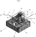
- is a perspective view showing a FTU mounted to a subsea foundation and connected to a central communication unit and a subsea unit,
- Fig. 3
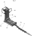
- is a perspective view showing the FTU connected to a fibre optic cable,
- Fig. 4a
- is a perspective view showing the FTU in a transport state,
- Fig. 4b
- is a perspective view showing the FTU in a usage state,
- Fig. 5a
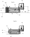
- is a side view showing the FTU in the transport state,
- Fig. 5b
- is a side view showing the FTU in the transport state with transportation lidre moved,
- Fig. 5c
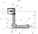
- is a side view showing the FTU in the usage state,
- Fig. 6a, Fig 6b and Fig 6c
- show different views of the FTU in the usage state,
- Fig. 7a
- is a cross-sectional view of the FTU in the usage state,
- Fig. 7b
- is a perspective view of the FTU in the usage state,
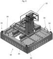
- Fig. 8
- is a top view showing the FTU mounted to a subsea foundation,
- Fig. 9
- is a perspective view of the FTU mounted to the subsea foundation.
- Shown in
fig. 2 , is the present invention in a perspective view. Similar to the prior art infig. 1 , also here a subseafibre termination unit 10 is attached to asubsea foundation 30 and is providing communication with acentral communication unit 2. The subseafibre termination unit 10 comprises two subsea communication connection interfaces 43, which allows twosubsea units 6 to be connected to thecentral communication unit 2 via afibre optic cable 3 and two pluggablefibre optic cables 5 connected to the connection interfaces 43. The subsea communication connection interfaces 43 can be a wet mate connector. Aproximal end 5a of the pluggablefibre optic cable 5 can be a wet mate connector. - The
fibre optic cable 3 can be equipped with acable bend restrictor 4 at theproximal end 3a of thefibre optic cable 3. - The subsea
fibre termination unit 10 comprises afirst frame 20 and asecond frame 40 pivotably connected to the first frame. -
Fig 7a and 7b show that thefirst frame 20 comprises afirst profile element 21 and afirst protection lid 22. In the present embodiment, thefirst protection lid 22 has an open box cross-sectional profile. Hence, thefirst frame 20 defines a first protective compartment between thefirst profile element 21 and afirst protection lid 22. - It is shown in
fig. 4a and 4b that thefirst frame 20 defines a base plane BP. -
Fig. 4a and 4b show that thesecond frame 40 has afirst end 40a, in which thesecond frame 40 is pivotably connected to thefirst frame 20, thereby defining a pivoting axis PA. The second frame has asecond end 40b, in which a subseaconnection communication interface 43 is provided. Hence, there is a distance between the subseacommunication connection interface 43 and the pivoting axis PA. -
Fig 6a and 6c show that thesecond frame 40 comprises asecond profile element 41 and asecond protection lid 42. In present embodiment, both thesecond profile element 41 and asecond protection lid 42 have a U-shaped or an open box cross-sectional profile. Hence, thesecond frame 40 defines a second protective compartment between thesecond profile element 41 and asecond protection lid 42. - The
first profile element 21 and thefirst protection lid 22 as well as thesecond profile element 41 and thesecond protection lid 42 may be joined by a suitable joining method such bolting or welding. -
Fig 5a shows that thesecond frame 40 defines alongitudinal axis 140 between itsfirst end 40a and itssecond end 40b. - The subsea
fibre termination unit 10 is configured to be in one of two states. In afirst state 1S, shown infig 4a and5a , thelongitudinal axis 140 of thesecond frame 40 is parallel to the base plane BP. In asecond state 2S, shown infig. 4b and5c , thelongitudinal axis 140 of thesecond frame 40 is perpendicular to the base plane BP. - The
first state 1S is a state in which the subseafibre termination unit 10 can be transported easily. Hence, thefirst state 1S is a transport state. Thesecond state 2S is a state in which the subseafibre termination unit 10 can be used subsea. Hence, thesecond state 2S is a usage state. - As shown in
fig 5a , there is a first distance D1 between the subseacommunication connection interface 43 and the base plane BP in the first state S1. In the second state S2, shown infig 5c , there is a second distance D2 between the subseacommunication connection interface 43 and the base plane BP. The second distance D2 is considerably larger than the first distance D1. - The subsea
fibre termination unit 10 further comprises afirst locking mechanism 51, shown infig 5a-5c , configured to secure thesecond frame 40 relative to thefirst frame 20 in the first state S1. Thefirst locking mechanism 51 is securing thesecond end 40b of thesecond frame 40 to thefirst frame 20 in the first state S1. Thefirst locking mechanism 51 is a bolted joint. - The subsea
fibre termination unit 10 further comprises asecond locking mechanism 52, shown infig 5a-5c , configured to secure thesecond frame 40 relative to thefirst frame 20 in the second state S2. Thesecond locking mechanism 52 is securing thesecond frame 40 to thefirst frame 20. Thesecond locking mechanism 52 is a bolted joint. Here, thesecond locking mechanism 52 is securing thesecond frame 40 to thefirst frame 20 via afirst profile element 21 secured to thefirst frame 20 as shown infig 7b . Thefirst profile element 21 is aligned with the base plane BP. -
Figs 3 ,4a and 4b show that thesecond frame 40 of thesubsea termination unit 10 comprises a ROV andprotection bar 47 and aROV bar 48. - The parts of the subsea
fibre termination unit 10 which enable communication will now be described. Infig. 7b , it is shown that thefibre termination unit 10 further comprises acommunication cable 26 and afibre termination terminal 28 in addition to the twosubsea communication connectors 43 in the form of wet mate connectors. - As described above, the two
subsea communication connectors 43 are provided in thesecond end 40b of thesecond frame 40, at a distance from the pivoting axis PA. The twosubsea communication connectors 43 are accessible from the outside of the subseafibre termination unit 10 and are hence not provided within the second protective compartment of thesecond frame 40. - The
fibre termination terminal 28 is secured to thefirst frame 20 within the first protective compartment. As shown infig. 7a , thefibre optic cable 3 is received into the first protective compartment of thefirst frame 20 and is terminated at thefibre termination terminal 28. -
Fig 7a and 7b also show that there are twocommunication cables 26, one for eachconnector 43, which are guided from thefibre termination terminal 28 along and thefirst frame 20 inside the first protective compartment and further along thesecond frame 40 inside the second protective compartment to a rear side of the subseacommunication connection interface 43. The twocommunication cables 26 are terminated at each of the subsea communication connection interfaces 43. Hence, communication is provided between the subseacommunication connection interface 43 and thefibre optic cable 3 via thecommunication cable 26 and thefibre termination terminal 28. -
Fig 7a and 7b show that thefibre termination unit 10 further comprises abend guard 24 secured to thesecond frame 40 adjacent to the pivoting axis PA. Thebend guard 24 is provided with acurved surface 25 faced towards thecommunication cables 26. Thecommunication cables 26 are guided from thefirst frame 20 to thesecond frame 40 via thebend guard 24. - As shown in
fig 7b , thecommunication cables 26 are arranged in a loop around thefibre termination terminal 28 along thefirst frame 20. This allows thecommunication cables 26 to move relative to thefirst frame 20 and thesecond frame 40 during movement of thesecond frame 40 between thefirst state 1S and thesecond state 2S and prevents undesired bending of thecommunication cables 26. The movement of thecommunication cable 26 relative to thefirst frame 20 and/or thesecond frame 40 is limited by fasteners such as cable ties. - The
fibre optic cable 3 is terminated in thefibre termination terminal 28 of the subseafibre termination unit 10 in a workshop or factory when the fibre optic cable is spooled on to a reel prior to installation offshore. - During transport, the subsea
fibre termination unit 10 is in thefirst state 1S which makes it compact and easier to handle. Moreover, the subseafibre termination unit 10 is robust and provides protection of thefibre optic cable 26 during transport and installation. - The
fibre termination unit 10 is typically attached to asubsea foundation 30 on board of an installation vessel. Thefibre termination unit 10 is in thefirst state 1S when it is attached to thesubsea foundation 30. Thefirst frame 20 of thefibre termination unit 10 is bolted to attachment rails 32 of thesubsea foundation 30 as shown infig. 8 and9 . Alternatively, thefibre termination unit 10 may be lowered down to thesubsea foundation 30 and is attached to the foundation subsea, for example by the use of appropriate guiding and landing interface. - In the present embodiment, the
first frame 20 is rigidly attached to a singlesubsea foundation 30 where thefirst frame 20 is placed in the centre of thesubsea foundation 30. Thesubsea foundation 30 may be a mud mat or a rock mat or another type of foundation. - The
fibre termination unit 10 is moved to thesecond state 2S prior to overboarding. For this purpose, locking bolts and nuts are removed to release thefirst locking mechanism 51 and to remove aremovable transportation lid 23. Theremovable transportation lid 23 is protecting thecommunication cables 26 in the area adjacent to thebend guard 24 during transport. - The
second frame 40 is moved to thesecond state 2S with the help of a crane from the installation vessel or an actuating mechanism. Once thesecond frame 40 has reached thesecond state 2S, thesecond locking mechanism 52 is secured by installing and tightening bolts and nuts. - As shown in
fig 9 , thesubsea foundation 30 may be lifted by crane with the help of liftingeyes 33 and positioned subsea by a remotely operated vehicle by means of ROV bars 34. - After installation subsea, the subsea
communication connection interface 43 is provided in a position above the seabed which makes it easy to connect equipment to the subseacommunication connection interface 43 by means of a remotely operated vehicle. To support this operation, thesubsea termination unit 10 is equipped with the ROV andprotection bar 47 and theROV bar 48. - In one embodiment, the
fibre optic cable 3 may be considered to be a part of the subseafibre termination unit 10. In a further embodiment, thefibre optic cable 3 may be considered to be separate from the subseafibre termination unit 10. - In an alternative embodiment, the
fibre termination terminal 28 and the subseacommunication connection interface 43 are one unit. Here theproximal end 3a of the fibre optic cable is terminated in the combinedfibre termination terminal 28 and the subseacommunication connection interface 43 unit in a workshop or factory when the fibre optic cable is spooled on to a reel prior to installation offshore. In this embodiment, the subseafibre termination unit 10 will be without the communication cable (26) and bend guard (24). - In an alternative embodiment, the subsea
fibre termination unit 10 is in thefirst state 1S when it is attached to thesubsea foundation 30 and is unfolded to thesecond state 2S after landing on the sea floor by means of a remotely operated vehicle or a remotely controlled actuating mechanism. The first and second locking mechanisms (51, 52) can be operated by a remotely operated vehicle or a remotely controlled actuating mechanism. - In yet another alternative embodiment, at least one of the
first profile element 21 and/orsecond profile element 41 and/or thefirst protection lid 22 and/orsecond protection lid 42 is facing the curved surface of the bend guard when the subseafibre termination unit 10 is in its first state S1 thus making theremovable transportation lid 23 redundant. -
- a subsea fibre termination unit (FTU) (10),
- a central communication unit (2),
- a fibre optic cable (3),
- a proximal end (3a) of the fibre optic cable (3),
- a distal end (3b) of the fibre optic cable (3),
- a cable bend restrictor (4)
- a pluggable fibre optic cable (5)
- a proximal end (5a) of the pluggable fibre optic cable (5),
- a first frame (20),
- a first profile element (21),
- a first protection lid (22),
- a removable transportation lid (23),
- a bend guard (24),
- a curved surface (25) of the bend guard (24),
- a communication cable (26),
- a fibre termination terminal (28),
- a subsea foundation (30),
- an attachment rail (32),
- a lifting eye (33),
- a ROV bar (34) for the subsea foundation (30),
- a second frame (40),
- a first end (40a),
- a second end (40b),
- a second profile element (41),
- a second protection lid (42),
- a subsea communication connection interface (43),
- a ROV and protection bar (47),
- a ROV bar (48),
- a first locking mechanism (51),
- a second locking mechanism (52)
- a base plane (BP),
- is a first distance (D1),
- a second distance (D2),
- a longitudinal axis (140),
- a pivoting axis (PA),
- a first state (1S),
- a second state (2S).
Claims (15)
- A subsea fibre termination unit (10) for subsea termination of a fibre optic cable (3), characterized in that the subsea fibre termination unit (10) comprises:- a first frame (20) attachable to a subsea foundation (30);- a second frame (40) comprising a subsea communication connection interface (43);- a fibre termination terminal (28) connectable to a proximal end (3a) of a fibre optic cable (3);wherein the second frame (40) is pivotably connected to the first frame (20) thereby defining a pivoting axis (PA).
- The subsea fibre termination unit (10) for subsea termination of the fibre optic cable (3) according to claim 1, wherein:- the second frame (40) has a first end (40a), in which the second frame (40) is pivotably connected to the first frame (20),- the second frame has a second end (40b), in which the subsea connection communication interface (43) is provided.
- The subsea fibre termination unit (10) for subsea termination of the fibre optic cable (3) according to claim 2; wherein:- the first frame (20) defines a base plane (BP);- the second frame (40) defines a longitudinal axis (140) between its first end (40a) and its second end (40b);wherein the subsea fibre termination unit (10) is configured to be in one of the following states:- a first state (1S), in which the longitudinal axis (140) of the second frame (40) is aligned with the base plane (BP);- a second state (2S), in which the longitudinal axis (140) of the second frame (40) is protruding away from the base plane (BP).
- The subsea fibre termination unit (10) for subsea termination of the fibre optic cable (3) according to any of the previous claims, wherein the subsea fibre termination unit (10) comprises a first locking mechanism (51) configured to secure the second frame (40) relative to the first frame (20) in the first state (S1).
- The subsea fibre termination unit (10) for subsea termination of the fibre optic cable (3) according to any of the previous claims, wherein the subsea fibre termination unit (10) comprises a second locking mechanism (52) configured to secure the second frame (40) relative to the first frame (20) in the second state (S2).
- The subsea fibre termination unit (10) for subsea termination of the fibre optic cable (3) according to any one of the previous claims, wherein:- the subsea fibre termination unit (10) comprises a bend guard (24) connected to the first frame (20) and/or the second frame (40) adjacent to the pivoting axis (PA);- the fibre termination terminal (28) is secured to the first frame (20);- a communication cable (26) is guided from the fibre termination terminal (28) along the first frame (20) and further along the second frame (40) to the subsea communication connection interface (43) via the bend guard (24).
- The subsea fibre termination unit (10) for subsea termination of the fibre optic cable (3) according to claim 6, wherein the communication cable (26) is arranged in a loop along the first frame (20).
- The subsea fibre termination unit (10) for subsea termination of the fibre optic cable (3) according to claim 7, wherein the communication cable (26) is arranged in a loop around the fibre termination terminal (28) along the first frame (20).
- The subsea fibre termination unit (10) for subsea termination of the fibre optic cable (3) according to any one of claims 6 to 8, wherein the bend guard (24) is provided with a curved surface (25) faced towards the communication cable (26).
- The subsea fibre termination unit (10) for subsea termination of the fibre optic cable (3) according to any one of claims 6 to 9, wherein the communication cable (26) is allowed to move relative to the first frame (20) and/or the second frame (40) during movement of the second frame (40) between the first state (1S) and the second state (2S).
- The subsea fibre termination unit (10) for subsea termination of the fibre optic cable (3) according to any of the previous claims, wherein the first frame (20) defines a first protective compartment for the fibre termination terminal (28) and a part of the communication cable (26).
- The subsea fibre termination unit (10) for subsea termination of the fibre optic cable (3) according to claim 11, wherein the first frame (20) comprises a first profile element (21) and a first protection lid (22).
- The subsea fibre termination unit (10) for subsea termination of the fibre optic cable (3) according to any of the previous claims, wherein the second frame (40) defines a second protective compartment for a part of the communication cable (26).
- The subsea fibre termination unit (10) for subsea termination of the fibre optic cable (3) according to claim 13, wherein the second frame (40) comprises a second profile element (41) and a second protection lid (42).
- The subsea fibre termination unit (10) for subsea termination of the fibre optic cable (3) according to any of the previous claims, wherein the subsea fibre termination unit (10) comprises a removable transportation lid (23) secured to the first frame (20) and/or second frame (40); wherein the removable transportation lid (23) is facing the curved surface (25) of the bend guard (24) when the subsea fibre termination unit (10) is in its first state (S1); and wherein the communication cable (26) is provided between the removable transportation lid (23) and the bend guard (24) when the when the subsea fibre termination unit (10) is in its first state (S1).
Priority Applications (1)
| Application Number | Priority Date | Filing Date | Title |
|---|---|---|---|
| EP21306224.3A EP4148473B1 (en) | 2021-09-08 | 2021-09-08 | A subsea fibre termination unit |
Applications Claiming Priority (1)
| Application Number | Priority Date | Filing Date | Title |
|---|---|---|---|
| EP21306224.3A EP4148473B1 (en) | 2021-09-08 | 2021-09-08 | A subsea fibre termination unit |
Publications (2)
| Publication Number | Publication Date |
|---|---|
| EP4148473A1 true EP4148473A1 (en) | 2023-03-15 |
| EP4148473B1 EP4148473B1 (en) | 2026-04-08 |
Family
ID=77998907
Family Applications (1)
| Application Number | Title | Priority Date | Filing Date |
|---|---|---|---|
| EP21306224.3A Active EP4148473B1 (en) | 2021-09-08 | 2021-09-08 | A subsea fibre termination unit |
Country Status (1)
| Country | Link |
|---|---|
| EP (1) | EP4148473B1 (en) |
Citations (6)
| Publication number | Priority date | Publication date | Assignee | Title |
|---|---|---|---|---|
| US5110224A (en) * | 1989-11-15 | 1992-05-05 | Stc Plc | Flexible cable termination with swivel couplings |
| US20100038090A1 (en) | 2008-08-13 | 2010-02-18 | Vetco Gray Controls Limited | Umbilical termination assemblies |
| US20100059229A1 (en) * | 2008-09-11 | 2010-03-11 | Deep Down, Inc. | Loose tube flying lead assembly |
| US20160097906A1 (en) * | 2014-10-07 | 2016-04-07 | Aker Subsea Limited | Apparatus with substantially rigid support |
| US20190257170A1 (en) * | 2018-02-20 | 2019-08-22 | Oceaneering International, Inc. | Versatile Flying Lead (HFL) Termhead System |
| US20190352993A1 (en) * | 2017-01-06 | 2019-11-21 | Vetco Gray Scandinavia As | Connection system for a multi-bore flying lead or umbilical |
Family Cites Families (1)
| Publication number | Priority date | Publication date | Assignee | Title |
|---|---|---|---|---|
| WO2005112574A2 (en) * | 2004-05-14 | 2005-12-01 | Exxonmobil Upstream Research Company | Flying lead connector and method for making subsea connections |
-
2021
- 2021-09-08 EP EP21306224.3A patent/EP4148473B1/en active Active
Patent Citations (6)
| Publication number | Priority date | Publication date | Assignee | Title |
|---|---|---|---|---|
| US5110224A (en) * | 1989-11-15 | 1992-05-05 | Stc Plc | Flexible cable termination with swivel couplings |
| US20100038090A1 (en) | 2008-08-13 | 2010-02-18 | Vetco Gray Controls Limited | Umbilical termination assemblies |
| US20100059229A1 (en) * | 2008-09-11 | 2010-03-11 | Deep Down, Inc. | Loose tube flying lead assembly |
| US20160097906A1 (en) * | 2014-10-07 | 2016-04-07 | Aker Subsea Limited | Apparatus with substantially rigid support |
| US20190352993A1 (en) * | 2017-01-06 | 2019-11-21 | Vetco Gray Scandinavia As | Connection system for a multi-bore flying lead or umbilical |
| US20190257170A1 (en) * | 2018-02-20 | 2019-08-22 | Oceaneering International, Inc. | Versatile Flying Lead (HFL) Termhead System |
Also Published As
| Publication number | Publication date |
|---|---|
| EP4148473B1 (en) | 2026-04-08 |
Similar Documents
| Publication | Publication Date | Title |
|---|---|---|
| US7086807B2 (en) | Subsea connection apparatus | |
| US10954652B2 (en) | Assembly and method for installing a subsea cable | |
| US5333691A (en) | ROV installable junction plate and method | |
| AU2009269833C1 (en) | Marine connection system and method | |
| US20030167997A1 (en) | Subsea deployable drum for laying lines | |
| US9874000B2 (en) | Subsurface mining vehicle and method for collecting mineral deposits from a sea bed at great depths and transporting said deposits to a floating vessel | |
| CN103282598B (en) | Device for handling hoses of a working well for a drilling rig | |
| AU2015202772A1 (en) | Assembly for mooring a pile with a mooring line and method implemented with said assembly | |
| EP2425095B1 (en) | Subsea system | |
| US5667341A (en) | Apparatus for signal and data transmission for controlling and monitoring underwater pile drivers, cut-off equipment and similar work units | |
| EP4148473B1 (en) | A subsea fibre termination unit | |
| GB2323907A (en) | Method and apparatus for connecting underwater conduits | |
| US7699353B2 (en) | Compliant splice | |
| JP4685525B2 (en) | Cable connecting device and underwater composite structure | |
| CN112086928A (en) | Connection structure of floating platform and submarine cable | |
| GB2321665A (en) | Seismic cables | |
| US20120193102A1 (en) | Remote subsea connection equipment | |
| WO1986000353A1 (en) | Underwater operating system | |
| US5249891A (en) | Guideline system for underwater observation camera systems | |
| US5996525A (en) | Bellmouth exit angle adapter | |
| GB2354751A (en) | Apparatus and method for positioning subaqueous articles |
Legal Events
| Date | Code | Title | Description |
|---|---|---|---|
| PUAI | Public reference made under article 153(3) epc to a published international application that has entered the european phase |
Free format text: ORIGINAL CODE: 0009012 |
|
| STAA | Information on the status of an ep patent application or granted ep patent |
Free format text: STATUS: THE APPLICATION HAS BEEN PUBLISHED |
|
| AK | Designated contracting states |
Kind code of ref document: A1 Designated state(s): AL AT BE BG CH CY CZ DE DK EE ES FI FR GB GR HR HU IE IS IT LI LT LU LV MC MK MT NL NO PL PT RO RS SE SI SK SM TR |
|
| STAA | Information on the status of an ep patent application or granted ep patent |
Free format text: STATUS: REQUEST FOR EXAMINATION WAS MADE |
|
| 17P | Request for examination filed |
Effective date: 20230915 |
|
| RBV | Designated contracting states (corrected) |
Designated state(s): AL AT BE BG CH CY CZ DE DK EE ES FI FR GB GR HR HU IE IS IT LI LT LU LV MC MK MT NL NO PL PT RO RS SE SI SK SM TR |
|
| GRAP | Despatch of communication of intention to grant a patent |
Free format text: ORIGINAL CODE: EPIDOSNIGR1 |
|
| STAA | Information on the status of an ep patent application or granted ep patent |
Free format text: STATUS: GRANT OF PATENT IS INTENDED |
|
| INTG | Intention to grant announced |
Effective date: 20251125 |
|
| GRAS | Grant fee paid |
Free format text: ORIGINAL CODE: EPIDOSNIGR3 |
|
| GRAA | (expected) grant |
Free format text: ORIGINAL CODE: 0009210 |
|
| STAA | Information on the status of an ep patent application or granted ep patent |
Free format text: STATUS: THE PATENT HAS BEEN GRANTED |
|
| AK | Designated contracting states |
Kind code of ref document: B1 Designated state(s): AL AT BE BG CH CY CZ DE DK EE ES FI FR GB GR HR HU IE IS IT LI LT LU LV MC MK MT NL NO PL PT RO RS SE SI SK SM TR |
|
| REG | Reference to a national code |
Ref country code: CH Ref legal event code: F10 Free format text: ST27 STATUS EVENT CODE: U-0-0-F10-F00 (AS PROVIDED BY THE NATIONAL OFFICE) Effective date: 20260408 Ref country code: GB Ref legal event code: FG4D |
|
| REG | Reference to a national code |
Ref country code: DE Ref legal event code: R096 Ref document number: 602021051547 Country of ref document: DE |
|
| REG | Reference to a national code |
Ref country code: IE Ref legal event code: FG4D |