EP4148425A1 - System and method for testing of monocrystalline components - Google Patents
System and method for testing of monocrystalline components Download PDFInfo
- Publication number
- EP4148425A1 EP4148425A1 EP22190380.0A EP22190380A EP4148425A1 EP 4148425 A1 EP4148425 A1 EP 4148425A1 EP 22190380 A EP22190380 A EP 22190380A EP 4148425 A1 EP4148425 A1 EP 4148425A1
- Authority
- EP
- European Patent Office
- Prior art keywords
- monocrystalline
- probe
- population
- components
- component
- Prior art date
- Legal status (The legal status is an assumption and is not a legal conclusion. Google has not performed a legal analysis and makes no representation as to the accuracy of the status listed.)
- Granted
Links
Images




Classifications
-
- G—PHYSICS
- G01—MEASURING; TESTING
- G01N—INVESTIGATING OR ANALYSING MATERIALS BY DETERMINING THEIR CHEMICAL OR PHYSICAL PROPERTIES
- G01N29/00—Investigating or analysing materials by the use of ultrasonic, sonic or infrasonic waves; Visualisation of the interior of objects by transmitting ultrasonic or sonic waves through the object
- G01N29/04—Analysing solids
- G01N29/043—Analysing solids in the interior, e.g. by shear waves
-
- G—PHYSICS
- G01—MEASURING; TESTING
- G01N—INVESTIGATING OR ANALYSING MATERIALS BY DETERMINING THEIR CHEMICAL OR PHYSICAL PROPERTIES
- G01N29/00—Investigating or analysing materials by the use of ultrasonic, sonic or infrasonic waves; Visualisation of the interior of objects by transmitting ultrasonic or sonic waves through the object
- G01N29/22—Details, e.g. general constructional or apparatus details
- G01N29/24—Probes
- G01N29/2468—Probes with delay lines
-
- G—PHYSICS
- G01—MEASURING; TESTING
- G01N—INVESTIGATING OR ANALYSING MATERIALS BY DETERMINING THEIR CHEMICAL OR PHYSICAL PROPERTIES
- G01N29/00—Investigating or analysing materials by the use of ultrasonic, sonic or infrasonic waves; Visualisation of the interior of objects by transmitting ultrasonic or sonic waves through the object
- G01N29/04—Analysing solids
- G01N29/06—Visualisation of the interior, e.g. acoustic microscopy
- G01N29/0654—Imaging
- G01N29/069—Defect imaging, localisation and sizing using, e.g. time of flight diffraction [TOFD], synthetic aperture focusing technique [SAFT], Amplituden-Laufzeit-Ortskurven [ALOK] technique
-
- G—PHYSICS
- G01—MEASURING; TESTING
- G01N—INVESTIGATING OR ANALYSING MATERIALS BY DETERMINING THEIR CHEMICAL OR PHYSICAL PROPERTIES
- G01N29/00—Investigating or analysing materials by the use of ultrasonic, sonic or infrasonic waves; Visualisation of the interior of objects by transmitting ultrasonic or sonic waves through the object
- G01N29/04—Analysing solids
- G01N29/07—Analysing solids by measuring propagation velocity or propagation time of acoustic waves
-
- G—PHYSICS
- G01—MEASURING; TESTING
- G01N—INVESTIGATING OR ANALYSING MATERIALS BY DETERMINING THEIR CHEMICAL OR PHYSICAL PROPERTIES
- G01N29/00—Investigating or analysing materials by the use of ultrasonic, sonic or infrasonic waves; Visualisation of the interior of objects by transmitting ultrasonic or sonic waves through the object
- G01N29/22—Details, e.g. general constructional or apparatus details
- G01N29/26—Arrangements for orientation or scanning by relative movement of the head and the sensor
- G01N29/262—Arrangements for orientation or scanning by relative movement of the head and the sensor by electronic orientation or focusing, e.g. with phased arrays
-
- G—PHYSICS
- G01—MEASURING; TESTING
- G01N—INVESTIGATING OR ANALYSING MATERIALS BY DETERMINING THEIR CHEMICAL OR PHYSICAL PROPERTIES
- G01N29/00—Investigating or analysing materials by the use of ultrasonic, sonic or infrasonic waves; Visualisation of the interior of objects by transmitting ultrasonic or sonic waves through the object
- G01N29/44—Processing the detected response signal, e.g. electronic circuits specially adapted therefor
- G01N29/4472—Mathematical theories or simulation
-
- G—PHYSICS
- G01—MEASURING; TESTING
- G01N—INVESTIGATING OR ANALYSING MATERIALS BY DETERMINING THEIR CHEMICAL OR PHYSICAL PROPERTIES
- G01N2291/00—Indexing codes associated with group G01N29/00
- G01N2291/02—Indexing codes associated with the analysed material
- G01N2291/028—Material parameters
- G01N2291/0289—Internal structure, e.g. defects, grain size, texture
-
- G—PHYSICS
- G01—MEASURING; TESTING
- G01N—INVESTIGATING OR ANALYSING MATERIALS BY DETERMINING THEIR CHEMICAL OR PHYSICAL PROPERTIES
- G01N2291/00—Indexing codes associated with group G01N29/00
- G01N2291/10—Number of transducers
- G01N2291/106—Number of transducers one or more transducer arrays
Definitions
- the present invention relates to a system and a method for testing of monocrystalline components.
- Non-destructive evaluation (NDE) methods such as ultrasonic testing procedures are commonly used to examine components (e.g., gas turbine engine components) for detecting and characterizing flaws in the components without damaging the components themselves.
- ultrasonic testing may involve transmission of ultrasonic waves through a portion of interest associated with the component. The ultrasonic waves may then be reflected back by deformities or discontinuities present in the portion of interest of the component. Measurement and evaluation of the reflected ultrasonic waves may permit determination of the presence and the characteristics of the flaws.
- Inspection of monocrystalline components may be problematic due to anisotropic material properties, as a result of which a path of propagation of the ultrasonic waves varies with a direction of propagation. This may distort propagation of the ultrasonic wave transmitted through the monocrystalline component and complicate signal interpretation based on reflected ultrasonic waves. Thus, a flaw actually present in the component may not be reliably detected. Additionally, propagation of ultrasonic waves may also depend on a crystallographic orientation of the monocrystalline component. Therefore, each monocrystalline component having individual crystallographic orientation is different in terms of inspection.
- a method for testing of a population of monocrystalline components includes obtaining a plurality of component parameters associated with the population of monocrystalline components.
- the plurality of component parameters includes a crystal orientation of each monocrystalline component from the population of monocrystalline components with respect to a coordinate axis common to the population of monocrystalline components, a three-dimensional geometry common to the population of monocrystalline components, and a material common to the population of monocrystalline components.
- the crystal orientation includes a crystal angle relative to the coordinate axis.
- the method further includes determining a statistical parameter associated with the population of monocrystalline components based on a statistical distribution of the crystal angle across the population of monocrystalline components.
- the method further includes generating a simulation model of the monocrystalline component representative of the population of monocrystalline components based at least partially on the statistical parameter, the three-dimensional geometry, and the material.
- the method further includes determining at least one probe parameter of an inspection probe arrangement based at least partially on the simulation model and a predetermined region of interest in the three-dimensional geometry.
- the inspection probe arrangement includes at least one probe configured to emit ultrasonic waves.
- the method further includes determining anisotropic delay laws based at least partially on the statistical parameter and the least one probe parameter.
- the method further includes controlling the at least one probe based on the anisotropic delay laws to emit the ultrasonic waves towards the region of interest of at least one monocrystalline component from the population of monocrystalline components in order to test the at least one monocrystalline component for one or more abnormalities.
- the method of the present invention provides a process for development and realisation of the inspection probe arrangement for testing of the monocrystalline components.
- the method involves prior determination of the component parameters associated with the population of monocrystalline components before testing of the monocrystalline components.
- the component parameters includes the crystal orientation of each monocrystalline component, the three-dimensional geometry of the monocrystalline component, and the material of the monocrystalline component.
- the method considers variation in the crystal orientation of the monocrystalline components across the population of monocrystalline components during development and realisation of the inspection probe arrangement itself.
- the method further includes determination of probe parameters based on the simulation model representing the population of the monocrystalline components.
- the simulation model is generated based on the material of the monocrystalline components, thus accounting for anisotropic material properties of the monocrystalline components for determining actual path of the ultrasonic waves in the monocrystalline component.
- the probe parameters may be determined based on the simulation model and considering the entire population of monocrystalline components.
- the method further includes determination of the anisotropic delay laws based at least partially on the statistical parameter and the least one probe parameter. Once the probe parameters are determined, the anisotropic delay laws may be determined for accurate targeting of the ultrasonic wave towards the region of interest.
- the anisotropic delay laws may consider anisotropic material properties of the monocrystalline component for determining delay laws of the inspection probe arrangement. Determination of the anisotropic delay laws may overcome complex geometrical challenges by allowing emission of ultrasonic waves towards the region of interest in the three-dimensional geometry of the monocrystalline components.
- the method enables real time testing of the monocrystalline components and interpretation of results eliminating the need for any post-processing since the method considers anisotropic material properties of monocrystalline components as well as variation in the crystal orientation across the population of monocrystalline components at the development stage of the inspection probe arrangement and before testing the monocrystalline components. Therefore, the inspection probe arrangement developed based on the present method may provide coverage of the population of monocrystalline components for testing using predetermined probe parameters and anisotropic delay laws. Consequently, post processing of images obtained during testing is not required.
- inspection probe arrangement may be compatible with the existing ultrasonic signal acquisition and interpretation systems.
- Use of anisotropic material properties for determination of the probe parameters and the anisotropic delay laws may significantly improve a signal to noise ratio of the inspection probe arrangement and ultrasonic images of the monocrystalline components are obtained more accurately and precisely.
- the statistical parameter includes a value of the at least one crystal angle that appears a maximum number of times in the population of monocrystalline components.
- the statistical parameter may be representative of the maximum number of monocrystalline components in the population of monocrystalline components.
- the simulation model may be generated based on the statistical parameter such that the simulation model may represent monocrystalline components having a crystal angle that appears a maximum number of times in the population of monocrystalline components.
- the method further includes determining a range of the at least one crystal angle for which the ultrasonic waves emitted by the at least one probe in response to the anisotropic delay laws at least partially overlap the region of interest. In some embodiments, the method further includes determining a subset of the monocrystalline components from the population of monocrystalline components having values of the at least one crystal angle that fall within the range of the at least one crystal angle. The range of the at least one crystal angle may represent the values of the crystal angles for which the inspection probe arrangement may be able to test the subset of the monocrystalline components based on the anisotropic delay laws.
- the method further includes determining a set of custom anisotropic delay laws such that the ultrasonic waves emitted by the at least one probe in response to the set of custom anisotropic delay laws at least partially overlap the region of interest for an outlier set of values of the at least one crystal angle that lies outside the range of the at least one crystal angle.
- the set of custom anisotropic delay laws may allow the inspection probe arrangement to test the monocrystalline components for which the at least one crystal angle may lie outside the range of the at least one crystal angle.
- the method further includes controlling the at least one probe based on the anisotropic delay laws and the custom anisotropic delay laws in order to test the population of the monocrystalline components.
- the inspection probe arrangement may be universal and may be used to test any monocrystalline component from the population of monocrystalline components based on the anisotropic delay laws and the set of custom anisotropic delay laws.
- the method further includes determining a crystal orientation of the at least one monocrystalline component. In some embodiments, the method further includes selecting the anisotropic delay laws or one of the set of custom anisotropic delay laws based on the crystal orientation. In some embodiments, the method further includes controlling the at least one probe based on the selected anisotropic delay laws or the one of the set of custom anisotropic delay laws in order to test the at least one monocrystalline component.
- the inspection probe arrangement may allow selection of the anisotropic delay laws or one of the set of custom anisotropic delay laws as applicable based on the crystal orientation of the at least one monocrystalline component in order to test the at least one monocrystalline component.
- the method further includes sequentially controlling the at least one probe based at least on the anisotropic delay laws and the set of custom anisotropic delays laws to test the at least one monocrystalline component if a crystal orientation of the at least one monocrystalline component is unknown.
- the inspection probe arrangement may allow testing of the monocrystalline components even if the crystal orientation of the at least one monocrystalline component is unknown during testing. Further, the method may eliminate measurement of the at least one crystal angle of the monocrystalline component during testing.
- the at least one probe is at least one phased array probe.
- a system for testing a population of monocrystalline components includes at least one probe configured to emit ultrasonic waves towards a region of interest.
- the system further includes a processor communicably coupled to the at least probe and configured to obtain a plurality of component parameters associated with the population of monocrystalline components.
- the plurality of component parameters includes at least one of a crystal orientation of each monocrystalline component from the population of monocrystalline components with respect to a coordinate axis common to the population of monocrystalline components, a three-dimensional geometry common to the population of monocrystalline components, and a material common to the population of monocrystalline components.
- the crystal orientation includes at least one crystal angle relative to the coordinate axis.
- the processor is further configured to determine a statistical parameter associated with the population of monocrystalline components based on a statistical distribution of the at least one crystal angle across the population of monocrystalline components.
- the processor is further configured to generate a simulation model of the monocrystalline component representative of the population of monocrystalline components based at least partially on the statistical parameter, the three-dimensional geometry, and the material.
- the processor is further configured to determine at least one probe parameter of an inspection probe arrangement based at least partially on the simulation model and a predetermined region of interest in the three-dimensional geometry.
- the inspection probe arrangement includes at least one probe configured to emit ultrasonic waves.
- the processor is further configured to determine anisotropic delay laws based at least partially on the statistical parameter and the least one probe parameter.
- the processor is further configured to control the at least one probe based on the anisotropic delay laws to emit the ultrasonic waves towards the region of interest of at least one monocrystalline component from the population of monocrystalline components in order to test the at least one monocrystalline component for one or more abnormalities
- the statistical parameter includes a value of the at least one crystal angle that appears a maximum number of times in the population of monocrystalline components.
- the processor is further configured to determine a range of the at least one crystal angle for which the ultrasonic waves emitted by the at least one probe in response to the anisotropic delay laws at least partially overlap the region of interest. In some embodiments, the processor is further configured to determine a subset of the monocrystalline components from the population of monocrystalline components having values of the at least one crystal angle that fall within the range of the at least one crystal angle.
- the processor is further configured to determine a set of custom anisotropic delay laws such that the ultrasonic waves emitted by the at least one probe in response to the set of custom anisotropic delay laws at least partially overlap the region of interest for an outlier set of values of the at least one crystal angle that lies outside the range of the at least one crystal angle.
- the processor is further configured to control the at least one probe based on the anisotropic delay laws and the set of custom anisotropic delay laws in order to test the population of the monocrystalline components.
- the processor is further configured to determine a crystal orientation of the at least one monocrystalline component. In some embodiments, the processor is further configured to select the anisotropic delay laws or one of the set of custom anisotropic delay laws based on the crystal orientation. In some embodiments, the processor is further configured to control the at least one probe based on the selected anisotropic delay laws or the one of the set of custom anisotropic delay laws in order to test the at least one monocrystalline component.
- the processor is further configured to sequentially control the at least one probe based at least on the anisotropic delay laws and the set of custom anisotropic delays laws in order to test the at least one monocrystalline component if a crystal orientation of the at least one monocrystalline component is unknown.
- the processor may control the at least one probe until all predefined delay laws ( anisotropic delay laws and the set of custom anisotropic delays laws) are used in order to test the at least one monocrystalline component if the crystal orientation of the at least one monocrystalline component is unknown. This may ensure testing of all the monocrystalline components in the population of monocrystalline components including the monocrystalline components for which the at least one crystal angle is from the outlier set of values of the at least one crystal angle.
- the at least one probe includes a plurality of probes and/or the at least one probe is at least one phased array probe.
- crystal generally refers to a three-dimensional ordered arrangement of atoms or molecules, which possesses symmetry characteristics.
- crystal orientation generally refers to an orientation state of the crystal in a structure of the material.
- the term “monocrystalline” generally refers to materials that are a single crystal or that are substantially a single crystal.
- the term “monocrystalline” generally refers to a single crystal material or one that includes a few (typically, 10 or fewer) large crystals that are oriented in the same crystallographic direction, i.e., having crystallographic planes with miller indices that are aligned to one another.
- the crystals in the monocrystalline materials may generally have same crystal orientation.
- anisotropic generally means having at least one property that differs in value when measured in at least one different direction.
- anisotropic material generally refers to a material having at least one property that differs in value when measured in at least one different direction.
- Sound wave generally refers to acoustic waves or pressure waves or vibrations traveling through gas, liquid or solid. Sound waves include ultrasonic, audio and infrasonic waves.
- the terms “ultrasound” or “ultrasonic wave” generally refer to the sound waves having a frequency above the upper limit of audible spectrum of the human ear, usually about 20,000 hertz.
- the terms “ultrasonic” and “ultrasound” are used interchangeably herein.
- an “ultrasonic probe” or “ultrasound probe” or “ultrasound echo probe” generally refers to an element capable of sending ultrasonic waves and/or receiving such waves.
- the term “probe” also encompasses accessory elements necessary for the probe to function in the several embodiments of the invention.
- the term "velocity profile” generally refers to velocity of a sound wave as a function of time and/or distance and/or direction in a material.
- the term “three-dimensional (3D) velocity profile” generally refers to velocity of a sound wave as a function of time and/or distance in a three-dimensional geometry of the material. It is generally known in the art that the velocity of a sound wave in a material depends on the mechanical properties of the material. Thus, the "3D velocity profile" may be a characteristic of the material and may be used for characterizing propagation of a sound wave inside the material.
- Figure 1 illustrates a schematic view of a system 100 for testing a population of monocrystalline components 102 according to an embodiment of the present invention.
- the monocrystalline component 102 is a blade of a gas turbine engine (not shown), however, the monocrystalline component 102 may include any solid part or a combination of parts.
- each monocrystalline component 102 includes an aerofoil 104, a root section 108, and a platform 106 positioned adjacent to the root section 108.
- the platform 106 is coupled to the root section 108 for mounting the aerofoil 104.
- the aerofoil 104 may extend longitudinally and/or radially outward in span from the platform 106 to an aerofoil tip 105.
- the platform 106 may extend generally transversely from a bottom 107 of the aerofoil 104.
- the root section 108 may be used for mounting the monocrystalline component 102 on a rotor (not shown) of the gas turbine engine.
- the root section 108 may transfer a torque to the rotor upon receiving a gas impingement on the aerofoil 104.
- the monocrystalline component 102 may include cooling channels (not shown) running between the root section 108 and the aerofoil 104.
- the monocrystalline component 102 as illustrated in Figure 1 is exemplary only and a configuration of the monocrystalline component 102 may take any conventional form, with or without the platform 106 or the root section 108.
- the monocrystalline component 102 may be formed integrally with a disk in a blisk-type configuration that does not include the root section 108.
- the monocrystalline component 102 may include an anisotropic metallic material.
- the monocrystalline component 102 may be produced using directional solidification casting techniques. Directional solidification may allow longitudinal grains of the monocrystalline component 102 to be aligned in a predetermined direction (crystallographic orientation), for example, along a direction of the aerofoil 104.
- the crystallographic orientation of the monocrystalline component 102 may vary across the population of monocrystalline components 102. The crystallographic orientation is interchangeably referred to hereinafter as "the crystal orientation".
- centrifugal forces may force the monocrystalline component 102 outward and induce loading forces into the root section 108. Overtime, such forces may induce abnormalities or defects (e.g., cracks) within the root section 108 due to fatigue at locations that may be radially inward from the platform 106. Accordingly, the monocrystalline component 102 may need to be inspected by an inspection probe arrangement 101 of the system 100 to ensure that the monocrystalline component 102 does not include any defects.
- the abnormalities may occur in the root section 108 of the monocrystalline component 102 where the centrifugal loading is greatest, and a complex geometry of the cooling channels may cause high stress concentrations. The abnormalities may therefore most likely occur in a specific region of the monocrystalline component 102. Such abnormalities may be detected though the inspection probe arrangement 101.
- the inspection probe arrangement 101 may inspect a crack-susceptible region of the monocrystalline component 102.
- the system 100 or the inspection probe arrangement 101 includes at least one probe 110 configured to detect the one or more abnormalities occurring in the monocrystalline component 102.
- the at least one probe 110 is interchangeably referred to hereinafter as "the probe 110".
- the probe 110 may be placed in a position contacting the monocrystalline component 102 radially outward from the platform 106 to inspect the root section 108.
- the probe 110 may utilize ultrasonic waves for detection of the one or more abnormalities.
- the probe 110 may allow inspection of the monocrystalline component 102 in an installed state within the gas turbine engine.
- the ultrasonic waves may be emitted precisely into a region of the root section 108 in which the one or more abnormalities are expected and which, therefore, needs to be inspected. Such a region may be referred to as a region of interest.
- the probe 110 is configured to emit the ultrasonic waves towards the predetermined region of interest.
- the probe 110 may include one or more ultrasonic elements that emit the ultrasonic waves which propagate into the monocrystalline component 102, for example, towards the region of interest.
- the probe 110 may include an array of the ultrasonic elements.
- the ultrasonic waves may be moved in space to scan the region of interest by sequentially activating each ultrasonic element through an inspection program.
- the ultrasonic waves may get reflected when the waves encounter an outer surface of the monocrystalline component 102.
- the probe 110 may convert the reflected ultrasonic waves into electrical signals which may then be used to generate internal images of the monocrystalline component 102 for further analysis. Any abnormality in the monocrystalline component 102 may also reflect or scatter the incident ultrasonic waves. Thus, the reflected ultrasonic waves may be detected by the probe 110 or a separate probe to infer presence of any abnormality.
- the system 100 or the inspection probe arrangement 101 further includes a processor 120 communicably coupled to the at least probe 110 via a cable 111.
- the probe 110 is configured to obtain a three-dimensional (3D) ultrasound image of the region of interest responsive to instructions from the processor 120, e.g., at appropriate times before or during an inspection process.
- the processor 120 may be embodied in a number of different ways.
- the processor 120 may be embodied as various processing means, such as one or more of a microprocessor or other processing elements, a coprocessor, or various other computing or processing devices including integrated circuits such as, for example, an ASIC (application specific integrated circuit), an FPGA (field programmable gate array), or the like.
- the processor 120 may be configured to execute instructions stored in a memory provided with the processor 120 or otherwise accessible to the processor 120.
- the memory may include a cache or random-access memory for the processor 120.
- the memory may be separate from the processor 120, such as a cache memory of a processor, a system memory, or other memory.
- the processor 120 may represent an entity (e.g., physically embodied in circuitry - in the form of processing circuitry) capable of performing operations according to some embodiments while configured accordingly.
- the processor 120 when the processor 120 is embodied as an ASIC, FPGA, or the like, the processor 120 may have specifically configured hardware for conducting the operations described herein.
- the processor 120 when the processor 120 may be embodied as an executor of software instructions, the instructions may specifically configure the processor 120 to perform the operations described herein.
- the processor 120 is coupled to a display device 112.
- external boundaries and dimensions of the monocrystalline component 102, internal boundaries and dimensions of the monocrystalline component 102, and any internal defects within the monocrystalline component 102 may be displayed in real-time on the display device 112 during the inspection process.
- the boundaries, dimensions, and defects are displayed on the display device 112 in real-time three-dimensional (3D) imaging.
- the system 100 may first need to be instituted or configured to be able to test one monocrystalline component 102 from the population of monocrystalline components 102. The steps involved in instituting the system 100 will be described hereinafter in detail.
- Figure 2 illustrates a schematic perspective view of an example of the monocrystalline component 102 from the population of monocrystalline components 102.
- the processor 120 is configured to obtain a plurality of component parameters 115 associated with the population of monocrystalline components 102.
- the component parameters 115 may include attributes of the monocrystalline component 102 based on manufacturing data of the population of monocrystalline components 102.
- the manufacturing data may include, but not limited to, serial number of monocrystalline components 102, manufacturing limits, material, geometry, etc.
- the manufacturing limits may indicate a maximum and a minimum attribute (e.g., tolerance) of the monocrystalline components 102 in the population of monocrystalline components 102.
- the population of monocrystalline components 102 may have a common characteristic such as geometry, material, etc.
- the manufacturing data may be obtained from a database of the population of monocrystalline components 102.
- the manufacturing data may be obtained electronically through a server using wireless communication or through offline means.
- the monocrystalline component 102 defines a coordinate axis 114 common to the population of monocrystalline components 102.
- the coordinate axis 114 includes mutually orthogonal x, y, and z-axes.
- the coordinate axis 114 is also referred to as a primary axis of the monocrystalline component 102.
- Conventional Miller indices 118 of a cubic system e.g., body centred cubic or a face centred cubic crystal
- a crystal 116 of the monocrystalline component 102 may have an orientation which can be defined using such Miller indices 118.
- the Miller index 118 is also referred to as a secondary axis of the monocrystalline component 102. Only one crystal 116 is shown for the purpose of illustration, however, the monocrystalline component 102 may include a number of crystals 116.
- the crystals 116 of the monocrystalline component 102 may have same orientation throughout the monocrystalline component 102 due to manufacturing of the monocrystalline component 102 using directional solidification.
- the crystal orientation 113 includes at least one crystal angle A relative to the coordinate axis 114.
- the at least one crystal angle A includes the angles ⁇ , ⁇ and ⁇ made by the three orthogonal axes [100], [010] and [001] with the coordinate axis 114, respectively.
- the at least one crystal angle A is interchangeably referred to hereinafter as the crystal angle A.
- the monocrystalline component 102 may be elastically anisotropic. Therefore, properties (e.g., mechanical properties) of the monocrystalline component 102 may vary with the orientation of the crystals 116, and thus, it may be advantageous to control the crystal orientation 113 during manufacturing of the monocrystalline component 102. Further, velocity of a sound wave in the monocrystalline component 102 may be dependent on a direction of travel of the sound wave in the monocrystalline component 102. Thus, anisotropy causes propagation of ultrasonic waves in the monocrystalline component 102 dependent on a direction of travel.
- the component parameters 115 include at least one of: the crystal orientation 113 of each monocrystalline component 102 from the population of monocrystalline components 102 with respect to the coordinate axis 114 common to the population of monocrystalline components 102; a three-dimensional (3D) geometry 117 common to the population of monocrystalline components 102; and a material 119 common to the population of monocrystalline components 102.
- the crystal orientation 113 includes the at least one crystal angle A, i.e., the angles ⁇ , ⁇ and ⁇ .
- the 3D geometry 117 may include a computer aided design (CAD) model of the monocrystalline component 102.
- the crystal angle A obtained from the manufacturing data may be first converted into a different coordinate system before being further processed by the processor 120.
- each monocrystalline component 102 in the population of monocrystalline components 102 may include a serial number or a part number. Serial numbers of the monocrystalline components 102 may be obtained from the manufacturing data. Further, a population size and manufacturing limits may also be determined from the manufacturing data. The population size may represent a number of the monocrystalline components 102 in the population of monocrystalline components 102.
- Figures 3A-3C illustrate examples of statistical distributions 130, 132, 134 of the at least one crystal angle A, i.e., the angles ⁇ , ⁇ and ⁇ , respectively.
- the statistical distribution 130 is a histogram illustrating relative frequencies of occurrence of different values of the angle ⁇ in the population of monocrystalline components 102.
- the statistical distributions 132, 134 are histograms illustrating relative frequencies of occurrence of different values of the angles ⁇ and ⁇ in the population of monocrystalline components 102, respectively.
- the processor 120 is further configured to determine a statistical parameter 140, 142, 144 associated with the population of monocrystalline components 102 based on the statistical distribution 130, 132, 134 of the at least one crystal angle A (or the angles ⁇ , ⁇ , and ⁇ ) across the population of monocrystalline components 102.
- the statistical parameters 140, 142, 144 may be calculated based on the statistical distributions 130, 132, 134 of the angles ⁇ , ⁇ , and ⁇ , respectively.
- the statistical parameter 140, 142, 144 includes a value 140a, 142a, 144a of the at least one crystal angle A (i.e., the respective angles ⁇ , ⁇ , and ⁇ ) that appears a maximum number of times in the population of monocrystalline components 102.
- the value 140a of the statistical parameter 140 may correspond to a value of the angle ⁇ having a maximum frequency of occurrence in the population of monocrystalline components 102.
- the value 140a may represent a value of the angle ⁇ possessed by a majority of the monocrystalline components 102 in the population of monocrystalline components 102.
- each of the values 140a, 142a, 144a may correspond to a mode of the respective statistical distribution 130, 132, 134.
- the statistical parameters 140, 142, 144 may be determined through any other statistical analysis as well without limiting the scope of the present invention.
- one or more of the statistical parameters 140, 142, 144 may correspond to a mean or a median of the corresponding statistical distributions 130, 132, 134.
- Figures 4A and 4B illustrate schematic views of a simulation model 150 of the monocrystalline component 102 according to an embodiment of the present invention. Specifically, Figure 4A illustrates a schematic front view and Figure 4B illustrates a schematic side view of the monocrystalline component 102, respectively.
- the processor 120 is further configured to generate the simulation model 150 of the monocrystalline component 102 representative of the population of monocrystalline components 102 based at least partially on the statistical parameter 140, 142, 144, the three-dimensional geometry 117, and the material 119.
- the simulation model 150 may represent the three-dimensional geometry 117 of the monocrystalline component 102 with the least one crystal angle A (or angles ⁇ , ⁇ , and ⁇ ) corresponding to the values 140a, 142a, 144a.
- the simulation model 150 may be obtained considering the most frequently occurring value of the crystal angle A (i.e., the angles ⁇ , ⁇ , and ⁇ ) of the monocrystalline component 102 in the population of monocrystalline components 102.
- the simulation model 150 may be generated by software (e.g., a computer application).
- the at least one probe 110 is configured to emit ultrasonic waves 152 towards a predetermined region of interest 124.
- the predetermined region of interest 124 corresponds to a portion in the three-dimensional geometry 117 of the monocrystalline component 102 where one or more abnormalities 126 is most likely expected to occur.
- the predetermined region of interest 124 may be obtained based on experimental trials and/or prior knowledge.
- the simulation model 150 may allow visualization of a path of the ultrasonic waves 152 in the volume of the monocrystalline component 102.
- the probe 110 is shown at a distance from the platform 106 of the monocrystalline component 102 for clarity.
- the probe 110 and the processor 120 are shown schematically in Figures 4A and 4B for the purpose of illustration. Specifically, the probe 110 and the processor 120 are superimposed on the simulation model 150 for descriptive purposes.
- the software may include a database of 3D velocity profiles of different materials.
- the 3D velocity profiles may be obtained by considering anisotropic properties of the material 119 of the monocrystalline component 102 since properties, such as velocity of sound in the monocrystalline component 102, may vary with a direction of propagation.
- the 3D velocity profiles may allow accurate determination and visualization of the path of the ultrasonic waves 152 in the material 119 of the monocrystalline component 102.
- the software may consider factors such as phase velocity, energy velocity, wave divergence, wave spreading, and/or wave skewing for determining the path of ultrasonic waves 152 in the monocrystalline component 102.
- the processor 120 is further configured to determine at least one probe parameter 122 based at least partially on the simulation model 150 and the predetermined region of interest 124 in the three-dimensional geometry 117.
- the at least one probe parameter 122 is interchangeably referred to hereinafter as "the probe parameter 122".
- the predetermined region of interest 124 is shown as having an oval shape, however, the present invention is not limited to any specific shape, and the oval shape of the region of interest 124 is merely used for the purpose of illustration.
- the probe parameter 122 may be determined based on the path of the ultrasonic waves 152 in the monocrystalline component 102.
- the probe parameter 122 may include a location of the probe 110 on the monocrystalline component 102 relative to the coordinate axis 114.
- the probe parameter 122 may define corresponding X, Y, and Z coordinates of the probe 110 relative to the coordinate axis 114.
- the probe parameter 122 may include an orientation of the probe 110 with respect to the coordinate axis 114.
- the probe parameter 122 may define corresponding angles made by the probe 110 with respect to the coordinate axis 114.
- the probe parameter 122 may include a type of wave to be used for inspection, for example, longitudinal waves, shear waves, or a combination thereof.
- the probe parameter 122 may further include a design and configuration (e.g., 1D, 1.5D, 2D, 2.5D, or 3D ultrasound probe) of the probe 110.
- the design of the probe 110 may include shape, frequency, dimensions, and number of ultrasonic emitter-receiver elements included in the probe 110.
- the probe parameter 122 may further include a pulse-echo configuration and a pitch-catch configuration.
- the pulse-echo configuration includes a single ultrasonic probe with the ultrasonic emitter and receiver elements configured in the same ultrasonic probe, while the pitch-catch configuration includes ultrasonic emitter and receiver elements incorporated in separate ultrasonic probes.
- the at least one probe 110 may include a plurality of probes 110.
- the probe 110 may include a phased array probe.
- the probe 110 may include a number of ultrasonic emitter-receiver elements.
- each ultrasonic element has its own electrical connection and is acoustically isolated from the other ultrasonic elements.
- the ultrasonic elements may emit the ultrasonic waves 152.
- the probe 110 may be placed on the monocrystalline component 102 such that the ultrasonic waves 152 are directed radially outward towards the region of interest 124.
- the probe 110 may include at least one non-phased array transducer configured to transmit the ultrasonic waves 152 into the monocrystalline component 102 at a plurality of angles.
- each ultrasonic element has its own pulser/receiver circuit and produces its own radio-frequency time/amplitude response to scan the region of interest 124.
- the processor 120 is further configured to determine anisotropic delay laws 156 (shown in Figure 4C ) based at least partially on the statistical parameter 140, 142, 144 and the least one probe parameter 122.
- Figure 4C illustrates an example of the anisotropic delay laws 156.
- the anisotropic delay laws 156 may include a set of rules that control a timing of emission of the ultrasonic waves 152 and reception to focus the ultrasonic waves 152 at a given point in the region of interest 124.
- the anisotropic delay laws 156 may be determined such that the probe 110 may successively generate the ultrasonic waves 152 with an angular coverage AC.
- the anisotropic delay laws 156 are determined through the software considering the 3D velocity profile of the material 119 of the monocrystalline component 102.
- the anisotropic delay laws 156 may include parameters associated with the ultrasonic waves 152 such as a wave angle P, a scan range S, a type of focus, and a type of scan.
- the wave angle P may be determined with respect to a reference axis A-A' of the probe 110.
- the wave angle P may include an initial angle P1, a final angle P2, a step size PS and a number of steps between the initial and final angles P1, P2. Individual responses of each ultrasonic element are added by the processor 120 and a resulting scan is displayed on the display device 112.
- the anisotropic delay laws 156 may further be determined in the software based on the region of interest 124, ability of the ultrasonic waves 152 to be reflected from the abnormality 126, a coverage around the region of interest 124, and a false detection of the abnormality 126.
- the simulation model 150 may be verified in experimental trials by validating the probe parameters 122 and the anisotropic delay laws 156 on a sample of the monocrystalline components 102 from the population of monocrystalline components 102 that correspond to values 140a, 142a, 144a of the respective angles ⁇ , ⁇ , ⁇ . Further, the probe parameters 122 and the anisotropic delay laws 156 are approved if validated in the experimental trials.
- the processor 120 is further configured to control the at least one probe 110 based on the anisotropic delay laws 156 to emit the ultrasonic waves 152 towards the region of interest 124 of at least one monocrystalline component 102 from the population of monocrystalline components 102 in order to test the at least one monocrystalline component 102 for the one or more abnormalities 126.
- the system 100 may be able to test a majority of monocrystalline components 102 from the population of monocrystalline components 102 since the anisotropic delay laws 156 are determined based on the statistical parameter 140, 142, 144.
- the processor 120 may record the ultrasonic waves 152 reflected from the monocrystalline component 102 or the one or more abnormalities 126 and the wave angle P at which the reflected ultrasonic waves are received.
- the ultrasonic waves 152 from the probe 110 are electronically swept through a range of wave angles P within the angular coverage AC based on the anisotropic delay laws 156.
- the probe 110 may be controlled to produce a fan-shaped sweep.
- the display device 112 may display the data recorded for the range of wave angles P as a polar plot, generating a cross-sectional view called a "sector scan" image.
- the sector scan image includes the reflections received from monocrystalline component 102 and/or the one or more abnormalities 126.
- An image of the one or more abnormalities 126 will be displayed in the display device 112 if present in the region of interest 124.
- a position and a depth of the one or more abnormalities 126 may be measured directly from the sector scan image.
- the processor 120 may transmit the data to an external device such as, but not limited to, a laptop computer, a personal digital assistant (PDA), a smartphone, a tablet device, a data collector, a server, or a network connection.
- PDA personal digital assistant
- Figure 5 illustrates an example of the statistical distribution 130 corresponding to the crystal angle A (e.g., the angle ⁇ ).
- the processor 120 is further configured to determine a range R1 of the at least one crystal angle A (e.g., the angle ⁇ in Figure 5 ) for which the ultrasonic waves 152 emitted by the at least one probe 110 in response to the anisotropic delay laws 156 at least partially overlap the region of interest 124.
- the range R1 may be determined through the software based on the simulation model 150 and the angular coverage AC of the ultrasonic waves 152 corresponding to different values of the angle ⁇ . In an alternative embodiment, the range R1 may be determined based on an empirical relationship between the angle ⁇ and a path of propagation of the ultrasonic waves 152 within the monocrystalline component 102. In some embodiments, the processor 120 is further configured to determine a subset N1 of the monocrystalline components 102 from the population of monocrystalline components 102 having values of the at least one crystal angle A (e.g., the angle ⁇ in Figure 5 ) that fall within the range R1 of the at least one crystal angle A. Similarly, a range is also determined corresponding to the angles ⁇ and ⁇ . However, the range R1 for the angle ⁇ is only shown for the purpose of illustration.
- the path of propagation of the ultrasonic waves 152 varies with the direction of propagation (and the at least one crystal angle A)
- the at least one crystal angle A may vary across the population of monocrystalline components 102, however, the region of interest 124 may remain at the same location.
- the processor 120 is further configured to determine an outlier set of values R2 that lies outside the range R1 of the at least one crystal angle A (e.g., the angle ⁇ in Figure 5 ) and for which the ultrasonic waves 152 emitted by the probe 110 in response to the anisotropic delay laws 156 may not overlap with the region of interest 124.
- an outlier set of values R2 that lies outside the range R1 of the at least one crystal angle A (e.g., the angle ⁇ in Figure 5 ) and for which the ultrasonic waves 152 emitted by the probe 110 in response to the anisotropic delay laws 156 may not overlap with the region of interest 124.
- the outlier set of values R2 may be determined based on the simulation model 150 corresponding to the outlier set of values R2 and the probe parameters 122 or the anisotropic delay laws 156 corresponding to the statistical parameter 140, 142, 144.
- a degree of overlap may be calculated for the at least one crystal angle A (e.g., the angle ⁇ in Figure 5 ) based on the ultrasonic waves 152 emitted by the probe 110 in response to the anisotropic delay laws 156 and the simulation model 150 corresponding to the at least one crystal angle A.
- the outlier set of values R2 may include all the values of the at least one crystal angle A (e.g., the angle ⁇ in Figure 5 ) where the degree of overlap is less than a predetermined threshold.
- an outlier set of values is also determined corresponding to the angles ⁇ and ⁇ .
- the outlier set of values R2 corresponding to the angle ⁇ is only shown for the purpose of illustration.
- the processor 120 is further configured to determine a set of custom anisotropic delay laws 162 (shown in Figure 6 ) such that the ultrasonic waves 152 emitted by the at least one probe 110 in response to the set of custom anisotropic delay laws 162 at least partially overlap the region of interest 124 for the outlier set of values R2 of the at least one crystal angle A (or the angles ⁇ , ⁇ and ⁇ ) that lies outside the range R1 of the at least one crystal angle A.
- a set of custom anisotropic delay laws 162 shown in Figure 6
- the processor 120 is further configured to determine a set of custom anisotropic delay laws 162 (shown in Figure 6 ) such that the ultrasonic waves 152 emitted by the at least one probe 110 in response to the set of custom anisotropic delay laws 162 at least partially overlap the region of interest 124 for the outlier set of values R2 of the at least one crystal angle A (or the angles ⁇ , ⁇ and ⁇ ) that lies outside the range R1 of the at least
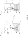
- Figure 6 illustrates an example of the simulation model 160 of the monocrystalline component 102 corresponding to a value of the crystal angle A from the outlier set of values R2 and the ultrasonic waves 152 emitted by the probe 110 in response to the anisotropic delay laws 156 and one of the set of custom anisotropic delay laws 162.
- the ultrasonic waves 152 do not overlap with the region of interest 124 when the probe 110 is controlled using anisotropic delay laws 156. Consequently, the one or more abnormalities 126 may not be detected. However, the ultrasonic waves 152 at least partially overlap with the region of interest 124 when the probe 110 is controlled using one of the set of custom anisotropic delay laws 162. Consequently, the one or more abnormalities 126 may be detected.
- the set of custom anisotropic delay laws 162 may be determined for different values of the at least one crystal angle A (or the angles ⁇ , ⁇ and ⁇ ) from the outlier set of values R2. Specifically, the set of custom anisotropic delay laws 162 may be determined for each individual value of the at least one crystal angle A (or the angles ⁇ , ⁇ and ⁇ ) from the outlier set of values R2 or a range of values of the at least one crystal angle A.
- the set of custom anisotropic delay laws 162 may be determined through the software based on a path of propagation of the ultrasonic waves 152 in the monocrystalline component 102. In some embodiments, the set of custom anisotropic delay laws 162 may be determined based on manual review of the path of propagation of the ultrasonic waves 152 in the software. Alternatively, the set of custom anisotropic delay laws 162 corresponding to the outlier set of values R2 may be determined automatically from the software based on spatial comparison of the ultrasonic waves 152 emitted by the probe 110 in response to different anisotropic delay laws with the region of interest 124.
- the probe parameters 122 may also be modified to allow the ultrasonic waves 152 emitted by the probe 110 to at least partially overlap the region of interest 124 for the outlier set of values R2.
- a suitable design and configuration e.g., 1D/1.5D/2D/2.5D phased array probe with different number of ultrasonic elements, dimension, and arrangement
- the probe parameter 122 may also be interchanged between pulse-echo configuration and pitch-catch configuration.
- the processor 120 is further configured to control the at least one probe 110 based on the anisotropic delay laws 156 and the set of custom anisotropic delay laws 162 in order to test the population of the monocrystalline components 102.
- the anisotropic delay laws 156 and the set of custom anisotropic delay laws 162 determined above may be used in the inspection process to test the population of the monocrystalline components 102.
- the system 100 allows prior determination of the component parameters 115 associated with the population of monocrystalline components 102 before testing of the monocrystalline components 102.
- the system 100 considers variation in the crystal orientation 113 of the monocrystalline components 102 across the population of monocrystalline components 102 during development and realisation of the inspection probe arrangement 101 itself.
- the simulation models 150, 160 may allow determination of an actual path of the ultrasonic waves 152 in the monocrystalline component 102.
- the anisotropic delay laws 156 and the set of custom anisotropic delay laws 162 may consider anisotropic material properties of the monocrystalline component 102 for determining delay laws of the inspection probe arrangement 101. Thus, the ultrasonic waves 152 may be accurately and reliably directed towards the region of interest 124. Further, the anisotropic delay laws 156 and the set of custom anisotropic delay laws 162 may allow the inspection probe arrangement 101 to test the entire population of the monocrystalline components 102. The set of custom anisotropic delay laws 162 may allow the inspection probe arrangement 101 to test the monocrystalline components 102 for which the at least one crystal angle A may lie outside the range R1 of the at least one crystal angle A.
- the system 100 may eliminate the need for any post-processing of an output of the inspection probe arrangement 101 since anisotropic material properties are already considered during the development and realisation of the inspection probe arrangement 101. This may allow immediate isolation of the monocrystalline components 102 during testing. Further, the testing of monocrystalline components 102 may be performed quickly and in a reliable manner.
- Figure 7 illustrates a block diagram of the system 100 according to an embodiment of the present invention.
- the processor 120 includes a memory 166 configured to store the crystal orientation 113 (or the at least one crystal angle A) of each monocrystalline component 102 in the population of monocrystalline components 102, the probe parameters 122, the anisotropic delay laws 156, and the set of custom anisotropic delay laws 162.
- the memory 166 may also be external to and communicably coupled to the processor 120.
- the memory 166 may also be configured to store data, such as the manufacturing data of the population of monocrystalline components 102, sector scan images, etc.
- the processor 120 may be configured to execute instructions stored in the memory 166. The functions, acts, or tasks illustrated in the figures or described herein may be performed by the processor 120 by executing the instructions stored in the memory 166.
- the memory 166 may be a main memory, a static memory, or a dynamic memory.
- the memory 166 may include, but may not limited to, computer readable storage media, such as various types of volatile and non-volatile storage media, including, but not limited to, random access memory, read-only memory, programmable read-only memory, electrically programmable read-only memory, electrically erasable read-only memory, flash memory, magnetic tape or disk, optical media, and/or the like.
- the probe 110 is configured to emit ultrasonic waves (e.g., the ultrasonic waves 152) towards the region of interest 124 of the monocrystalline component 102 based on inputs from the processor 120.
- the processor 120 is configured to determine a crystal orientation 168 of the at least one monocrystalline component 102.
- the crystal orientation 168 of the at least one monocrystalline component 102 may be determined from the manufacturing data of the population of monocrystalline components 102 (e.g., using a part number or a specification of the gas turbine engine).
- the processor 120 may determine the crystal orientation 168 based on manual input of the part number or the specification of gas turbine engine.
- the processor 120 is further configured to select the anisotropic delay laws 156 or one of the set of custom anisotropic delay laws 162 based on the crystal orientation 168.
- the processor 120 may select the anisotropic delay laws 156 when the crystal orientation 168 is within a range (e.g., the range R1) of the at least one crystal angle A. If the crystal orientation 168 belongs to an outlier set of the values (e.g., the outlier set of values R2), the processor 120 may select one of the set of custom anisotropic delay laws 162 which corresponds to that crystal orientation 168.
- the processor 120 is further configured to control the at least one probe 110 based on the selected anisotropic delay laws 156 or the one of the set of custom anisotropic delay laws 162 in order to test the at least one monocrystalline component 102.
- the system 100 may allow selection of the anisotropic delay laws 156 or one of the set of custom anisotropic delay laws 162 as applicable based on the crystal orientation 168 of the at least one monocrystalline component 102 in order to test the at least one monocrystalline component 102.
- the processor 120 is further configured to sequentially control the at least one probe 110 based at least on the anisotropic delay laws 156 and the set of custom anisotropic delays laws 162 to test the at least one monocrystalline component 102 if the crystal orientation (168) of the at least one monocrystalline component 102 is unknown.
- the processor 120 may obtain an output (e.g., a set of sectoral scan images) from the at least one probe 110 corresponding to the anisotropic delay laws 156 and the set of custom anisotropic delay laws 162.
- the output may be displayed through the display device 112 and may be verified manually for presence of one or more abnormalities (e.g., the one or more abnormalities 126).
- the system 100 may allow testing of the monocrystalline components 102 even if the crystal orientation (168) of the at least one monocrystalline component 102 is unknown during testing.
- Figure 8 is a flow chart illustrating a method 200 for testing of the population of monocrystalline components 102.
- the method 200 may be implemented using the system 100 of Figures 1-7 incorporating the teachings of the present invention.
- the method 200 includes obtaining the plurality of component parameters 115 associated with the population of monocrystalline components 102.
- the plurality of component parameters 115 includes at least one of: the crystal orientation 113 of each monocrystalline component 102 from the population of monocrystalline components 102 with respect to the coordinate axis 114 common to the population of monocrystalline components 102; the three-dimensional geometry 117 common to the population of monocrystalline components 102; and the material 119 common to the population of monocrystalline components 102.
- the crystal orientation 113 includes the at least one crystal angle A relative to the coordinate axis 114.
- the method 200 further includes determining the statistical parameter 140, 142, 144 associated with the population of monocrystalline components 102 based on the statistical distribution 130, 132, 134 of the at least one crystal angle A across the population of monocrystalline components 102.
- the statistical parameter 140, 142, 144 includes the value 140a, 142a, 144a of the at least one crystal angle A that appears a maximum number of times in the population of monocrystalline components 102.
- the method 200 further includes generating the simulation model 150 of the monocrystalline component 102 representative of the population of monocrystalline components 102 based at least partially on the statistical parameter 140, 142, 144, the three-dimensional geometry 117, and the material 119.
- the method 200 further includes determining the at least one probe parameter 122 of the inspection probe arrangement 101 based at least partially on the simulation model 150 and the predetermined region of interest 124 in the three-dimensional geometry 117.
- the inspection probe arrangement 101 includes the at least one probe 110 configured to emit the ultrasonic waves 152.
- the method 200 further includes determining the anisotropic delay laws 156 based at least partially on the statistical parameter 140, 142, 144 and the least one probe parameter 122.
- the method 200 further includes controlling the at least one probe 110 based on the anisotropic delay laws 156 to emit the ultrasonic waves 152 towards the region of interest 124 of at least one monocrystalline component 102 from the population of monocrystalline components 102 in order to test the at least one monocrystalline component 102 for the one or more abnormalities 126.
- the method 200 further includes determining the range R1 of the at least one crystal angle A for which the ultrasonic waves 152 emitted by the at least one probe 110 in response to the anisotropic delay laws 156 at least partially overlap the region of interest 124.
- the method 200 further includes determining the subset N1 of the monocrystalline components 102 from the population of monocrystalline components 102 having values of the at least one crystal angle A that fall within the range R1 of the at least one crystal angle A.
- the ultrasonic waves 152 emitted by the at least one probe 110 in response to the anisotropic delay laws 156 may be able to at least partially overlap the region of interest 124 for only a percentage (e.g., 70% or 80%) of the monocrystalline components 102 from the population of monocrystalline components 102. This is applicable for the monocrystalline components 102 for which the at least one crystal angle A lies within the range R1 of the at least one crystal angle A.
- the ultrasonic waves 152 emitted by the at least one probe 110 in response to the anisotropic delay laws 156 may not be able to overlap the region of interest 124.
- the population of monocrystalline components 102 may not be entirely tested based on the anisotropic delay laws 156, and hence, the population of monocrystalline components 102 may be insufficiently covered based on the anisotropic delay laws 156.
- the method 200 further includes determining the set of custom anisotropic delay laws 162 if the population of monocrystalline components 102 is insufficiently covered based on the anisotropic delay laws 156.
- the method 200 further includes determining the set of custom anisotropic delay laws 162 such that the ultrasonic waves 152 emitted by the at least one probe 110 in response to the set of custom anisotropic delay laws 162 at least partially overlap the region of interest 124 for the outlier set of values R2 of the at least one crystal angle A that lies outside the range R1 of the at least one crystal angle A.
- the method 200 determines the set of custom anisotropic delay laws 162 to cover the remaining population of the monocrystalline components 102 if the population of monocrystalline components 102 is insufficiently covered based on the anisotropic delay laws 156.
- the method 200 further includes controlling the at least one probe 110 based on the anisotropic delay laws 156 and the set of custom anisotropic delay laws 162 in order to test the population of the monocrystalline components 102.
- the method 200 further includes determining a crystal orientation 168 of the at least one monocrystalline component 102. In some embodiments, the method 200 further includes selecting the anisotropic delay laws 156 or one of the set of custom anisotropic delay laws 162 based on the crystal orientation 168. In some embodiments, the method 200 further includes controlling the at least one probe 110 based on the selected anisotropic delay laws 156 or the one of the set of custom anisotropic delay laws 162 in order to test the at least one monocrystalline component 102.
- the method 200 further includes sequentially controlling the at least one probe 110 based at least on the anisotropic delay laws 156 and the set of custom anisotropic delays laws 162 to test the at least one monocrystalline component 102 if the crystal orientation 168 of the at least one monocrystalline component 102 is unknown.
- system 100 for testing the population of monocrystalline components 102 of the present invention has largely been described above with reference to its use in gas turbine engines, however, the system 100 may also be used for many other applications for non-destructive testing of such monocrystalline components 102. Thus, the system 100 may be useful in non-destructive testing of various other components in other application areas.
Landscapes
- Physics & Mathematics (AREA)
- General Physics & Mathematics (AREA)
- Immunology (AREA)
- Chemical & Material Sciences (AREA)
- Analytical Chemistry (AREA)
- Biochemistry (AREA)
- General Health & Medical Sciences (AREA)
- Life Sciences & Earth Sciences (AREA)
- Health & Medical Sciences (AREA)
- Pathology (AREA)
- Acoustics & Sound (AREA)
- Algebra (AREA)
- Mathematical Analysis (AREA)
- Mathematical Optimization (AREA)
- Mathematical Physics (AREA)
- Pure & Applied Mathematics (AREA)
- Engineering & Computer Science (AREA)
- Signal Processing (AREA)
- Investigating Or Analyzing Materials By The Use Of Ultrasonic Waves (AREA)
Abstract
Description
- The present invention relates to a system and a method for testing of monocrystalline components.
- Non-destructive evaluation (NDE) methods such as ultrasonic testing procedures are commonly used to examine components (e.g., gas turbine engine components) for detecting and characterizing flaws in the components without damaging the components themselves. Typically, ultrasonic testing may involve transmission of ultrasonic waves through a portion of interest associated with the component. The ultrasonic waves may then be reflected back by deformities or discontinuities present in the portion of interest of the component. Measurement and evaluation of the reflected ultrasonic waves may permit determination of the presence and the characteristics of the flaws.
- Inspection of monocrystalline components (e.g., gas turbine blades) using ultrasonic testing procedures may be problematic due to anisotropic material properties, as a result of which a path of propagation of the ultrasonic waves varies with a direction of propagation. This may distort propagation of the ultrasonic wave transmitted through the monocrystalline component and complicate signal interpretation based on reflected ultrasonic waves. Thus, a flaw actually present in the component may not be reliably detected. Additionally, propagation of ultrasonic waves may also depend on a crystallographic orientation of the monocrystalline component. Therefore, each monocrystalline component having individual crystallographic orientation is different in terms of inspection.
- Conventional ultrasonic testing systems typically involve post-processing of ultrasonic images of the monocrystalline component obtained from the ultrasonic testing procedures to compensate for anisotropic material properties. The post-processing is based on complex velocity models obtained from investigation of wave propagation in anisotropic materials. Such post-processing techniques are time consuming and do not allow direct result interpretation since the ultrasonic images may need to be corrected before interpretation. Additionally, individual crystal orientation must be known or measured accurately for post-processing. Further, imaging algorithms may need to be corrected for each individual crystal orientation of the monocrystalline components.
- According to a first aspect there is provided a method for testing of a population of monocrystalline components. The method includes obtaining a plurality of component parameters associated with the population of monocrystalline components. The plurality of component parameters includes a crystal orientation of each monocrystalline component from the population of monocrystalline components with respect to a coordinate axis common to the population of monocrystalline components, a three-dimensional geometry common to the population of monocrystalline components, and a material common to the population of monocrystalline components. The crystal orientation includes a crystal angle relative to the coordinate axis. The method further includes determining a statistical parameter associated with the population of monocrystalline components based on a statistical distribution of the crystal angle across the population of monocrystalline components. The method further includes generating a simulation model of the monocrystalline component representative of the population of monocrystalline components based at least partially on the statistical parameter, the three-dimensional geometry, and the material. The method further includes determining at least one probe parameter of an inspection probe arrangement based at least partially on the simulation model and a predetermined region of interest in the three-dimensional geometry. The inspection probe arrangement includes at least one probe configured to emit ultrasonic waves. The method further includes determining anisotropic delay laws based at least partially on the statistical parameter and the least one probe parameter. The method further includes controlling the at least one probe based on the anisotropic delay laws to emit the ultrasonic waves towards the region of interest of at least one monocrystalline component from the population of monocrystalline components in order to test the at least one monocrystalline component for one or more abnormalities.
- The method of the present invention provides a process for development and realisation of the inspection probe arrangement for testing of the monocrystalline components. The method involves prior determination of the component parameters associated with the population of monocrystalline components before testing of the monocrystalline components. The component parameters includes the crystal orientation of each monocrystalline component, the three-dimensional geometry of the monocrystalline component, and the material of the monocrystalline component. Thus, the method considers variation in the crystal orientation of the monocrystalline components across the population of monocrystalline components during development and realisation of the inspection probe arrangement itself.
- The method further includes determination of probe parameters based on the simulation model representing the population of the monocrystalline components. The simulation model is generated based on the material of the monocrystalline components, thus accounting for anisotropic material properties of the monocrystalline components for determining actual path of the ultrasonic waves in the monocrystalline component. Further, the probe parameters may be determined based on the simulation model and considering the entire population of monocrystalline components.
- The method further includes determination of the anisotropic delay laws based at least partially on the statistical parameter and the least one probe parameter. Once the probe parameters are determined, the anisotropic delay laws may be determined for accurate targeting of the ultrasonic wave towards the region of interest. The anisotropic delay laws may consider anisotropic material properties of the monocrystalline component for determining delay laws of the inspection probe arrangement. Determination of the anisotropic delay laws may overcome complex geometrical challenges by allowing emission of ultrasonic waves towards the region of interest in the three-dimensional geometry of the monocrystalline components.
- The method enables real time testing of the monocrystalline components and interpretation of results eliminating the need for any post-processing since the method considers anisotropic material properties of monocrystalline components as well as variation in the crystal orientation across the population of monocrystalline components at the development stage of the inspection probe arrangement and before testing the monocrystalline components. Therefore, the inspection probe arrangement developed based on the present method may provide coverage of the population of monocrystalline components for testing using predetermined probe parameters and anisotropic delay laws. Consequently, post processing of images obtained during testing is not required.
- Additionally, elimination of post processing may allow immediate isolation of components with one or more abnormalities. Further, the inspection probe arrangement may be compatible with the existing ultrasonic signal acquisition and interpretation systems. Use of anisotropic material properties for determination of the probe parameters and the anisotropic delay laws may significantly improve a signal to noise ratio of the inspection probe arrangement and ultrasonic images of the monocrystalline components are obtained more accurately and precisely.
- In some embodiments, the statistical parameter includes a value of the at least one crystal angle that appears a maximum number of times in the population of monocrystalline components. Thus, the statistical parameter may be representative of the maximum number of monocrystalline components in the population of monocrystalline components. The simulation model may be generated based on the statistical parameter such that the simulation model may represent monocrystalline components having a crystal angle that appears a maximum number of times in the population of monocrystalline components.
- In some embodiments, the method further includes determining a range of the at least one crystal angle for which the ultrasonic waves emitted by the at least one probe in response to the anisotropic delay laws at least partially overlap the region of interest. In some embodiments, the method further includes determining a subset of the monocrystalline components from the population of monocrystalline components having values of the at least one crystal angle that fall within the range of the at least one crystal angle. The range of the at least one crystal angle may represent the values of the crystal angles for which the inspection probe arrangement may be able to test the subset of the monocrystalline components based on the anisotropic delay laws.
- In some embodiments, the method further includes determining a set of custom anisotropic delay laws such that the ultrasonic waves emitted by the at least one probe in response to the set of custom anisotropic delay laws at least partially overlap the region of interest for an outlier set of values of the at least one crystal angle that lies outside the range of the at least one crystal angle. The set of custom anisotropic delay laws may allow the inspection probe arrangement to test the monocrystalline components for which the at least one crystal angle may lie outside the range of the at least one crystal angle.
- In some embodiments, the method further includes controlling the at least one probe based on the anisotropic delay laws and the custom anisotropic delay laws in order to test the population of the monocrystalline components. Thus, the inspection probe arrangement may be universal and may be used to test any monocrystalline component from the population of monocrystalline components based on the anisotropic delay laws and the set of custom anisotropic delay laws.
- In some embodiments, the method further includes determining a crystal orientation of the at least one monocrystalline component. In some embodiments, the method further includes selecting the anisotropic delay laws or one of the set of custom anisotropic delay laws based on the crystal orientation. In some embodiments, the method further includes controlling the at least one probe based on the selected anisotropic delay laws or the one of the set of custom anisotropic delay laws in order to test the at least one monocrystalline component. Thus, the inspection probe arrangement may allow selection of the anisotropic delay laws or one of the set of custom anisotropic delay laws as applicable based on the crystal orientation of the at least one monocrystalline component in order to test the at least one monocrystalline component.
- In some embodiments, the method further includes sequentially controlling the at least one probe based at least on the anisotropic delay laws and the set of custom anisotropic delays laws to test the at least one monocrystalline component if a crystal orientation of the at least one monocrystalline component is unknown. Thus, the inspection probe arrangement may allow testing of the monocrystalline components even if the crystal orientation of the at least one monocrystalline component is unknown during testing. Further, the method may eliminate measurement of the at least one crystal angle of the monocrystalline component during testing.
- In some embodiments, the at least one probe is at least one phased array probe.
- According to a second aspect, there is provided a system for testing a population of monocrystalline components. The system includes at least one probe configured to emit ultrasonic waves towards a region of interest. The system further includes a processor communicably coupled to the at least probe and configured to obtain a plurality of component parameters associated with the population of monocrystalline components. The plurality of component parameters includes at least one of a crystal orientation of each monocrystalline component from the population of monocrystalline components with respect to a coordinate axis common to the population of monocrystalline components, a three-dimensional geometry common to the population of monocrystalline components, and a material common to the population of monocrystalline components. The crystal orientation includes at least one crystal angle relative to the coordinate axis. The processor is further configured to determine a statistical parameter associated with the population of monocrystalline components based on a statistical distribution of the at least one crystal angle across the population of monocrystalline components. The processor is further configured to generate a simulation model of the monocrystalline component representative of the population of monocrystalline components based at least partially on the statistical parameter, the three-dimensional geometry, and the material. The processor is further configured to determine at least one probe parameter of an inspection probe arrangement based at least partially on the simulation model and a predetermined region of interest in the three-dimensional geometry. The inspection probe arrangement includes at least one probe configured to emit ultrasonic waves. The processor is further configured to determine anisotropic delay laws based at least partially on the statistical parameter and the least one probe parameter. The processor is further configured to control the at least one probe based on the anisotropic delay laws to emit the ultrasonic waves towards the region of interest of at least one monocrystalline component from the population of monocrystalline components in order to test the at least one monocrystalline component for one or more abnormalities
- In some embodiments, the statistical parameter includes a value of the at least one crystal angle that appears a maximum number of times in the population of monocrystalline components.
- In some embodiments, the processor is further configured to determine a range of the at least one crystal angle for which the ultrasonic waves emitted by the at least one probe in response to the anisotropic delay laws at least partially overlap the region of interest. In some embodiments, the processor is further configured to determine a subset of the monocrystalline components from the population of monocrystalline components having values of the at least one crystal angle that fall within the range of the at least one crystal angle.
- In some embodiments, the processor is further configured to determine a set of custom anisotropic delay laws such that the ultrasonic waves emitted by the at least one probe in response to the set of custom anisotropic delay laws at least partially overlap the region of interest for an outlier set of values of the at least one crystal angle that lies outside the range of the at least one crystal angle.
- In some embodiments, the processor is further configured to control the at least one probe based on the anisotropic delay laws and the set of custom anisotropic delay laws in order to test the population of the monocrystalline components.
- In some embodiments, the processor is further configured to determine a crystal orientation of the at least one monocrystalline component. In some embodiments, the processor is further configured to select the anisotropic delay laws or one of the set of custom anisotropic delay laws based on the crystal orientation. In some embodiments, the processor is further configured to control the at least one probe based on the selected anisotropic delay laws or the one of the set of custom anisotropic delay laws in order to test the at least one monocrystalline component.
- In some embodiments, the processor is further configured to sequentially control the at least one probe based at least on the anisotropic delay laws and the set of custom anisotropic delays laws in order to test the at least one monocrystalline component if a crystal orientation of the at least one monocrystalline component is unknown. Thus, the processor may control the at least one probe until all predefined delay laws ( anisotropic delay laws and the set of custom anisotropic delays laws) are used in order to test the at least one monocrystalline component if the crystal orientation of the at least one monocrystalline component is unknown. This may ensure testing of all the monocrystalline components in the population of monocrystalline components including the monocrystalline components for which the at least one crystal angle is from the outlier set of values of the at least one crystal angle.
- In some embodiments, the at least one probe includes a plurality of probes and/or the at least one probe is at least one phased array probe.
- Embodiments will now be described by way of example only, with reference to the Figures, in which:
-
Figure 1 is a schematic view of an exemplary system for testing a population of monocrystalline components; -
Figure 2 is a schematic view of an example of the monocrystalline component; -
Figures 3A-3C illustrate examples of statistical distributions of at least one crystal angle; -
Figures 4A and 4B are schematic front and side views, respectively, of a simulation model of the monocrystalline component, according to an embodiment of the present invention; -
Figures 4C illustrates anisotropic delay laws, according to an embodiment of the present invention; -
Figure 5 is an example of the statistical distribution ofFigure 3A ; -
Figure 6 illustrates the simulation model corresponding to a value of the crystal angle from an outlier set of values and ultrasonic waves emitted by a probe in response to anisotropic delay laws and custom anisotropic delay laws, according to an embodiment of the present invention; -
Figure 7 is a block diagram of the system ofFigure 1 , according to another embodiment of the present invention; and -
Figure 8 is a flow chart illustrating a method for testing of the population of monocrystalline components, according to an embodiment of the present invention. - Aspects and embodiments of the present invention will now be discussed with reference to the accompanying figures. Further aspects and embodiments will be apparent to those skilled in the art.
- As used herein, the term "crystal" generally refers to a three-dimensional ordered arrangement of atoms or molecules, which possesses symmetry characteristics.
- As used herein, the term "crystal orientation" generally refers to an orientation state of the crystal in a structure of the material.
- As used herein, the term "monocrystalline" generally refers to materials that are a single crystal or that are substantially a single crystal. In other words, the term "monocrystalline" generally refers to a single crystal material or one that includes a few (typically, 10 or fewer) large crystals that are oriented in the same crystallographic direction, i.e., having crystallographic planes with miller indices that are aligned to one another. Thus, the crystals in the monocrystalline materials may generally have same crystal orientation.
- As used herein, the term "anisotropic" generally means having at least one property that differs in value when measured in at least one different direction. Thus, the term "anisotropic material" generally refers to a material having at least one property that differs in value when measured in at least one different direction.
- The term "sound wave" generally refers to acoustic waves or pressure waves or vibrations traveling through gas, liquid or solid. Sound waves include ultrasonic, audio and infrasonic waves.
- As used herein, the terms "ultrasound" or "ultrasonic wave" generally refer to the sound waves having a frequency above the upper limit of audible spectrum of the human ear, usually about 20,000 hertz. The terms "ultrasonic" and "ultrasound" are used interchangeably herein.
- As used herein, the term "probe", whether applied to an ultrasound probe, a photoacoustic probe, an excitation probe or otherwise, generally refers to an element that serves a signal generating function or a signal reception function or both. Thus, an "ultrasonic probe" or "ultrasound probe" or "ultrasound echo probe" generally refers to an element capable of sending ultrasonic waves and/or receiving such waves. The term "probe" also encompasses accessory elements necessary for the probe to function in the several embodiments of the invention.
- As used herein, the term "velocity profile" generally refers to velocity of a sound wave as a function of time and/or distance and/or direction in a material. As used herein, the term "three-dimensional (3D) velocity profile" generally refers to velocity of a sound wave as a function of time and/or distance in a three-dimensional geometry of the material. It is generally known in the art that the velocity of a sound wave in a material depends on the mechanical properties of the material. Thus, the "3D velocity profile" may be a characteristic of the material and may be used for characterizing propagation of a sound wave inside the material.
-
Figure 1 illustrates a schematic view of asystem 100 for testing a population ofmonocrystalline components 102 according to an embodiment of the present invention. In some embodiments, the population ofmonocrystalline components 102 may include a number of monocrystalline components 102(1), 102(2), 102(3), ...,102(N) (collectively, monocrystalline components 102), where N is an integer corresponding to a total number of monocrystalline components 102 (e.g., N = 10, 20, etc.) in the population ofmonocrystalline components 102. In the illustrated embodiment ofFigure 1 , themonocrystalline component 102 is a blade of a gas turbine engine (not shown), however, themonocrystalline component 102 may include any solid part or a combination of parts. - In some embodiments, each
monocrystalline component 102 includes anaerofoil 104, aroot section 108, and aplatform 106 positioned adjacent to theroot section 108. In some embodiments, theplatform 106 is coupled to theroot section 108 for mounting theaerofoil 104. Theaerofoil 104 may extend longitudinally and/or radially outward in span from theplatform 106 to anaerofoil tip 105. Theplatform 106 may extend generally transversely from abottom 107 of theaerofoil 104. In some embodiments, theroot section 108 may be used for mounting themonocrystalline component 102 on a rotor (not shown) of the gas turbine engine. In some embodiments, theroot section 108 may transfer a torque to the rotor upon receiving a gas impingement on theaerofoil 104. In some embodiments, themonocrystalline component 102 may include cooling channels (not shown) running between theroot section 108 and theaerofoil 104. - It should be noted that the
monocrystalline component 102 as illustrated inFigure 1 is exemplary only and a configuration of themonocrystalline component 102 may take any conventional form, with or without theplatform 106 or theroot section 108. For example, themonocrystalline component 102 may be formed integrally with a disk in a blisk-type configuration that does not include theroot section 108. - In some embodiments, the
monocrystalline component 102 may include an anisotropic metallic material. In some embodiments themonocrystalline component 102 may be produced using directional solidification casting techniques. Directional solidification may allow longitudinal grains of themonocrystalline component 102 to be aligned in a predetermined direction (crystallographic orientation), for example, along a direction of theaerofoil 104. In some embodiments, the crystallographic orientation of themonocrystalline component 102 may vary across the population ofmonocrystalline components 102. The crystallographic orientation is interchangeably referred to hereinafter as "the crystal orientation". - During operation, centrifugal forces may force the
monocrystalline component 102 outward and induce loading forces into theroot section 108. Overtime, such forces may induce abnormalities or defects (e.g., cracks) within theroot section 108 due to fatigue at locations that may be radially inward from theplatform 106. Accordingly, themonocrystalline component 102 may need to be inspected by aninspection probe arrangement 101 of thesystem 100 to ensure that themonocrystalline component 102 does not include any defects. - In some embodiments, the abnormalities may occur in the
root section 108 of themonocrystalline component 102 where the centrifugal loading is greatest, and a complex geometry of the cooling channels may cause high stress concentrations. The abnormalities may therefore most likely occur in a specific region of themonocrystalline component 102. Such abnormalities may be detected though theinspection probe arrangement 101. For example, theinspection probe arrangement 101 may inspect a crack-susceptible region of themonocrystalline component 102. - The
system 100 or theinspection probe arrangement 101 includes at least oneprobe 110 configured to detect the one or more abnormalities occurring in themonocrystalline component 102. The at least oneprobe 110 is interchangeably referred to hereinafter as "theprobe 110". Theprobe 110 may be placed in a position contacting themonocrystalline component 102 radially outward from theplatform 106 to inspect theroot section 108. In some embodiments, theprobe 110 may utilize ultrasonic waves for detection of the one or more abnormalities. In some embodiments, theprobe 110 may allow inspection of themonocrystalline component 102 in an installed state within the gas turbine engine. - In some embodiments, the ultrasonic waves may be emitted precisely into a region of the
root section 108 in which the one or more abnormalities are expected and which, therefore, needs to be inspected. Such a region may be referred to as a region of interest. Thus, theprobe 110 is configured to emit the ultrasonic waves towards the predetermined region of interest. - In some embodiments, the
probe 110 may include one or more ultrasonic elements that emit the ultrasonic waves which propagate into themonocrystalline component 102, for example, towards the region of interest. In some embodiments, theprobe 110 may include an array of the ultrasonic elements. In some embodiments, the ultrasonic waves may be moved in space to scan the region of interest by sequentially activating each ultrasonic element through an inspection program. - In some embodiments, the ultrasonic waves may get reflected when the waves encounter an outer surface of the
monocrystalline component 102. Theprobe 110 may convert the reflected ultrasonic waves into electrical signals which may then be used to generate internal images of themonocrystalline component 102 for further analysis. Any abnormality in themonocrystalline component 102 may also reflect or scatter the incident ultrasonic waves. Thus, the reflected ultrasonic waves may be detected by theprobe 110 or a separate probe to infer presence of any abnormality. - The
system 100 or theinspection probe arrangement 101 further includes aprocessor 120 communicably coupled to the at least probe 110 via acable 111. In some embodiments, theprobe 110 is configured to obtain a three-dimensional (3D) ultrasound image of the region of interest responsive to instructions from theprocessor 120, e.g., at appropriate times before or during an inspection process. - In some embodiments, the
processor 120 may be embodied in a number of different ways. For example, theprocessor 120 may be embodied as various processing means, such as one or more of a microprocessor or other processing elements, a coprocessor, or various other computing or processing devices including integrated circuits such as, for example, an ASIC (application specific integrated circuit), an FPGA (field programmable gate array), or the like. In some embodiments, theprocessor 120 may be configured to execute instructions stored in a memory provided with theprocessor 120 or otherwise accessible to theprocessor 120. In some embodiments, the memory may include a cache or random-access memory for theprocessor 120. Alternatively, or in addition, the memory may be separate from theprocessor 120, such as a cache memory of a processor, a system memory, or other memory. - As such, whether configured by hardware or by a combination of hardware and software, the
processor 120 may represent an entity (e.g., physically embodied in circuitry - in the form of processing circuitry) capable of performing operations according to some embodiments while configured accordingly. Thus, for example, when theprocessor 120 is embodied as an ASIC, FPGA, or the like, theprocessor 120 may have specifically configured hardware for conducting the operations described herein. Alternatively, as another example, when theprocessor 120 may be embodied as an executor of software instructions, the instructions may specifically configure theprocessor 120 to perform the operations described herein. - In some embodiments, the
processor 120 is coupled to adisplay device 112. As such, external boundaries and dimensions of themonocrystalline component 102, internal boundaries and dimensions of themonocrystalline component 102, and any internal defects within themonocrystalline component 102 may be displayed in real-time on thedisplay device 112 during the inspection process. In some embodiments, the boundaries, dimensions, and defects are displayed on thedisplay device 112 in real-time three-dimensional (3D) imaging. - For testing the
monocrystalline component 102, thesystem 100 may first need to be instituted or configured to be able to test onemonocrystalline component 102 from the population ofmonocrystalline components 102. The steps involved in instituting thesystem 100 will be described hereinafter in detail. -
Figure 2 illustrates a schematic perspective view of an example of themonocrystalline component 102 from the population ofmonocrystalline components 102. Referring now toFigures 1 and2 , theprocessor 120 is configured to obtain a plurality of component parameters 115 associated with the population ofmonocrystalline components 102. The component parameters 115 may include attributes of themonocrystalline component 102 based on manufacturing data of the population ofmonocrystalline components 102. - In some embodiments, the manufacturing data may include, but not limited to, serial number of
monocrystalline components 102, manufacturing limits, material, geometry, etc. The manufacturing limits may indicate a maximum and a minimum attribute (e.g., tolerance) of themonocrystalline components 102 in the population ofmonocrystalline components 102. In some embodiments, the population ofmonocrystalline components 102 may have a common characteristic such as geometry, material, etc. In some embodiments, the manufacturing data may be obtained from a database of the population ofmonocrystalline components 102. In some embodiments, the manufacturing data may be obtained electronically through a server using wireless communication or through offline means. - The
monocrystalline component 102 defines a coordinateaxis 114 common to the population ofmonocrystalline components 102. In some embodiments, the coordinateaxis 114 includes mutually orthogonal x, y, and z-axes. The coordinateaxis 114 is also referred to as a primary axis of themonocrystalline component 102.Conventional Miller indices 118 of a cubic system (e.g., body centred cubic or a face centred cubic crystal) are also shown inFigure 2 . Acrystal 116 of themonocrystalline component 102 may have an orientation which can be defined usingsuch Miller indices 118. TheMiller index 118 is also referred to as a secondary axis of themonocrystalline component 102. Only onecrystal 116 is shown for the purpose of illustration, however, themonocrystalline component 102 may include a number ofcrystals 116. - In some embodiments, the
crystals 116 of themonocrystalline component 102 may have same orientation throughout themonocrystalline component 102 due to manufacturing of themonocrystalline component 102 using directional solidification. In the cubic system, specification of orientation in space of any two orthogonal axes, such as [100] and [001], will fully define acrystal orientation 113. Thecrystal orientation 113 includes at least one crystal angle A relative to the coordinateaxis 114. Specifically, the at least one crystal angle A includes the angles α, β and γ made by the three orthogonal axes [100], [010] and [001] with the coordinateaxis 114, respectively. The at least one crystal angle A is interchangeably referred to hereinafter as the crystal angle A. - In some embodiments, the
monocrystalline component 102 may be elastically anisotropic. Therefore, properties (e.g., mechanical properties) of themonocrystalline component 102 may vary with the orientation of thecrystals 116, and thus, it may be advantageous to control thecrystal orientation 113 during manufacturing of themonocrystalline component 102. Further, velocity of a sound wave in themonocrystalline component 102 may be dependent on a direction of travel of the sound wave in themonocrystalline component 102. Thus, anisotropy causes propagation of ultrasonic waves in themonocrystalline component 102 dependent on a direction of travel. - The component parameters 115 include at least one of: the
crystal orientation 113 of eachmonocrystalline component 102 from the population ofmonocrystalline components 102 with respect to the coordinateaxis 114 common to the population ofmonocrystalline components 102; a three-dimensional (3D) geometry 117 common to the population ofmonocrystalline components 102; and a material 119 common to the population ofmonocrystalline components 102. Thecrystal orientation 113 includes the at least one crystal angle A, i.e., the angles α, β and γ. In some embodiments, the 3D geometry 117 may include a computer aided design (CAD) model of themonocrystalline component 102. In some embodiments, the crystal angle A obtained from the manufacturing data may be first converted into a different coordinate system before being further processed by theprocessor 120. - In some embodiments, each
monocrystalline component 102 in the population ofmonocrystalline components 102 may include a serial number or a part number. Serial numbers of themonocrystalline components 102 may be obtained from the manufacturing data. Further, a population size and manufacturing limits may also be determined from the manufacturing data. The population size may represent a number of themonocrystalline components 102 in the population ofmonocrystalline components 102. -
Figures 3A-3C illustrate examples ofstatistical distributions statistical distribution 130 is a histogram illustrating relative frequencies of occurrence of different values of the angle α in the population ofmonocrystalline components 102. Similarly, thestatistical distributions monocrystalline components 102, respectively. - It should be understood that the
statistical distributions - Referring now to
Figures 1-3C , theprocessor 120 is further configured to determine astatistical parameter monocrystalline components 102 based on thestatistical distribution monocrystalline components 102. In some embodiments, thestatistical parameters statistical distributions - In some embodiments, the
statistical parameter value monocrystalline components 102. For example, thevalue 140a of thestatistical parameter 140 may correspond to a value of the angle α having a maximum frequency of occurrence in the population ofmonocrystalline components 102. Thus, thevalue 140a may represent a value of the angle α possessed by a majority of themonocrystalline components 102 in the population ofmonocrystalline components 102. Similarly, thevalues monocrystalline components 102. Therefore, each of thevalues statistical distribution - It should be understood that the
statistical parameters statistical parameters statistical distributions -
Figures 4A and 4B illustrate schematic views of asimulation model 150 of themonocrystalline component 102 according to an embodiment of the present invention. Specifically,Figure 4A illustrates a schematic front view andFigure 4B illustrates a schematic side view of themonocrystalline component 102, respectively. - Referring now to
Figures 1-4B , theprocessor 120 is further configured to generate thesimulation model 150 of themonocrystalline component 102 representative of the population ofmonocrystalline components 102 based at least partially on thestatistical parameter simulation model 150 may represent the three-dimensional geometry 117 of themonocrystalline component 102 with the least one crystal angle A (or angles α, β, and γ) corresponding to thevalues simulation model 150 may be obtained considering the most frequently occurring value of the crystal angle A (i.e., the angles α, β, and γ) of themonocrystalline component 102 in the population ofmonocrystalline components 102. In some embodiments, thesimulation model 150 may be generated by software (e.g., a computer application). - The at least one
probe 110 is configured to emitultrasonic waves 152 towards a predetermined region ofinterest 124. The predetermined region ofinterest 124 corresponds to a portion in the three-dimensional geometry 117 of themonocrystalline component 102 where one ormore abnormalities 126 is most likely expected to occur. The predetermined region ofinterest 124 may be obtained based on experimental trials and/or prior knowledge. In some embodiments, thesimulation model 150 may allow visualization of a path of theultrasonic waves 152 in the volume of themonocrystalline component 102. In the illustrated embodiments ofFigures 4A and 4B , theprobe 110 is shown at a distance from theplatform 106 of themonocrystalline component 102 for clarity. It is to be noted that theprobe 110 and theprocessor 120 are shown schematically inFigures 4A and 4B for the purpose of illustration. Specifically, theprobe 110 and theprocessor 120 are superimposed on thesimulation model 150 for descriptive purposes. - In some embodiments, the software may include a database of 3D velocity profiles of different materials. The 3D velocity profiles may be obtained by considering anisotropic properties of the material 119 of the
monocrystalline component 102 since properties, such as velocity of sound in themonocrystalline component 102, may vary with a direction of propagation. Thus, the 3D velocity profiles may allow accurate determination and visualization of the path of theultrasonic waves 152 in the material 119 of themonocrystalline component 102. In some embodiments, the software may consider factors such as phase velocity, energy velocity, wave divergence, wave spreading, and/or wave skewing for determining the path ofultrasonic waves 152 in themonocrystalline component 102. - The
processor 120 is further configured to determine at least oneprobe parameter 122 based at least partially on thesimulation model 150 and the predetermined region ofinterest 124 in the three-dimensional geometry 117. The at least oneprobe parameter 122 is interchangeably referred to hereinafter as "theprobe parameter 122". In the illustrated examples ofFigures 4A and 4B , the predetermined region ofinterest 124 is shown as having an oval shape, however, the present invention is not limited to any specific shape, and the oval shape of the region ofinterest 124 is merely used for the purpose of illustration. - In some embodiments, the
probe parameter 122 may be determined based on the path of theultrasonic waves 152 in themonocrystalline component 102. In some embodiments, theprobe parameter 122 may include a location of theprobe 110 on themonocrystalline component 102 relative to the coordinateaxis 114. Thus, theprobe parameter 122 may define corresponding X, Y, and Z coordinates of theprobe 110 relative to the coordinateaxis 114. Additionally, theprobe parameter 122 may include an orientation of theprobe 110 with respect to the coordinateaxis 114. Thus, theprobe parameter 122 may define corresponding angles made by theprobe 110 with respect to the coordinateaxis 114. - In some embodiments, the
probe parameter 122 may include a type of wave to be used for inspection, for example, longitudinal waves, shear waves, or a combination thereof. Theprobe parameter 122 may further include a design and configuration (e.g., 1D, 1.5D, 2D, 2.5D, or 3D ultrasound probe) of theprobe 110. The design of theprobe 110 may include shape, frequency, dimensions, and number of ultrasonic emitter-receiver elements included in theprobe 110. - In some embodiments, the
probe parameter 122 may further include a pulse-echo configuration and a pitch-catch configuration. The pulse-echo configuration includes a single ultrasonic probe with the ultrasonic emitter and receiver elements configured in the same ultrasonic probe, while the pitch-catch configuration includes ultrasonic emitter and receiver elements incorporated in separate ultrasonic probes. In some embodiments, the at least oneprobe 110 may include a plurality ofprobes 110. - In some embodiments, the
probe 110 may include a phased array probe. In some embodiments, theprobe 110 may include a number of ultrasonic emitter-receiver elements. In some embodiments, each ultrasonic element has its own electrical connection and is acoustically isolated from the other ultrasonic elements. The ultrasonic elements may emit theultrasonic waves 152. In some embodiments, theprobe 110 may be placed on themonocrystalline component 102 such that theultrasonic waves 152 are directed radially outward towards the region ofinterest 124. In an alternative embodiment, theprobe 110 may include at least one non-phased array transducer configured to transmit theultrasonic waves 152 into themonocrystalline component 102 at a plurality of angles. In some embodiments, each ultrasonic element has its own pulser/receiver circuit and produces its own radio-frequency time/amplitude response to scan the region ofinterest 124. - The
processor 120 is further configured to determine anisotropic delay laws 156 (shown inFigure 4C ) based at least partially on thestatistical parameter probe parameter 122.Figure 4C illustrates an example of theanisotropic delay laws 156. In some embodiments, theanisotropic delay laws 156 may include a set of rules that control a timing of emission of theultrasonic waves 152 and reception to focus theultrasonic waves 152 at a given point in the region ofinterest 124. Referring now toFigures 1-4C , theanisotropic delay laws 156 may be determined such that theprobe 110 may successively generate theultrasonic waves 152 with an angular coverage AC. In some embodiments, theanisotropic delay laws 156 are determined through the software considering the 3D velocity profile of the material 119 of themonocrystalline component 102. - In some embodiments, the
anisotropic delay laws 156 may include parameters associated with theultrasonic waves 152 such as a wave angle P, a scan range S, a type of focus, and a type of scan. The wave angle P may be determined with respect to a reference axis A-A' of theprobe 110. In some embodiments, the wave angle P may include an initial angle P1, a final angle P2, a step size PS and a number of steps between the initial and final angles P1, P2. Individual responses of each ultrasonic element are added by theprocessor 120 and a resulting scan is displayed on thedisplay device 112. In some embodiments, theanisotropic delay laws 156 may further be determined in the software based on the region ofinterest 124, ability of theultrasonic waves 152 to be reflected from theabnormality 126, a coverage around the region ofinterest 124, and a false detection of theabnormality 126. - In some embodiments, the
simulation model 150 may be verified in experimental trials by validating theprobe parameters 122 and theanisotropic delay laws 156 on a sample of themonocrystalline components 102 from the population ofmonocrystalline components 102 that correspond tovalues probe parameters 122 and theanisotropic delay laws 156 are approved if validated in the experimental trials. - The
processor 120 is further configured to control the at least oneprobe 110 based on theanisotropic delay laws 156 to emit theultrasonic waves 152 towards the region ofinterest 124 of at least onemonocrystalline component 102 from the population ofmonocrystalline components 102 in order to test the at least onemonocrystalline component 102 for the one ormore abnormalities 126. Thesystem 100 may be able to test a majority ofmonocrystalline components 102 from the population ofmonocrystalline components 102 since theanisotropic delay laws 156 are determined based on thestatistical parameter - As the
monocrystalline component 102 is scanned by theprobe 110, theprocessor 120 may record theultrasonic waves 152 reflected from themonocrystalline component 102 or the one ormore abnormalities 126 and the wave angle P at which the reflected ultrasonic waves are received. During the inspection process, theultrasonic waves 152 from theprobe 110 are electronically swept through a range of wave angles P within the angular coverage AC based on theanisotropic delay laws 156. In some embodiments, theprobe 110 may be controlled to produce a fan-shaped sweep. - In some embodiments, the
display device 112 may display the data recorded for the range of wave angles P as a polar plot, generating a cross-sectional view called a "sector scan" image. The sector scan image includes the reflections received frommonocrystalline component 102 and/or the one ormore abnormalities 126. An image of the one ormore abnormalities 126 will be displayed in thedisplay device 112 if present in the region ofinterest 124. A position and a depth of the one ormore abnormalities 126 may be measured directly from the sector scan image. In some embodiments, theprocessor 120 may transmit the data to an external device such as, but not limited to, a laptop computer, a personal digital assistant (PDA), a smartphone, a tablet device, a data collector, a server, or a network connection. -
Figure 5 illustrates an example of thestatistical distribution 130 corresponding to the crystal angle A (e.g., the angle α). Referring now toFigures 1-5 , in some embodiments, theprocessor 120 is further configured to determine a range R1 of the at least one crystal angle A (e.g., the angle α inFigure 5 ) for which theultrasonic waves 152 emitted by the at least oneprobe 110 in response to theanisotropic delay laws 156 at least partially overlap the region ofinterest 124. - In some embodiments, the range R1 may be determined through the software based on the
simulation model 150 and the angular coverage AC of theultrasonic waves 152 corresponding to different values of the angle α. In an alternative embodiment, the range R1 may be determined based on an empirical relationship between the angle α and a path of propagation of theultrasonic waves 152 within themonocrystalline component 102. In some embodiments, theprocessor 120 is further configured to determine a subset N1 of themonocrystalline components 102 from the population ofmonocrystalline components 102 having values of the at least one crystal angle A (e.g., the angle α inFigure 5 ) that fall within the range R1 of the at least one crystal angle A. Similarly, a range is also determined corresponding to the angles β and γ. However, the range R1 for the angle α is only shown for the purpose of illustration. - Since the path of propagation of the
ultrasonic waves 152 varies with the direction of propagation (and the at least one crystal angle A), there may be some values of the crystal angle A for which theultrasonic waves 152 emitted by theprobe 110 in response to theanisotropic delay laws 156 may not overlap with the region ofinterest 124. The at least one crystal angle A may vary across the population ofmonocrystalline components 102, however, the region ofinterest 124 may remain at the same location. Thus, in some embodiments, theprocessor 120 is further configured to determine an outlier set of values R2 that lies outside the range R1 of the at least one crystal angle A (e.g., the angle α inFigure 5 ) and for which theultrasonic waves 152 emitted by theprobe 110 in response to theanisotropic delay laws 156 may not overlap with the region ofinterest 124. - In some embodiments, the outlier set of values R2 may be determined based on the
simulation model 150 corresponding to the outlier set of values R2 and theprobe parameters 122 or theanisotropic delay laws 156 corresponding to thestatistical parameter Figure 5 ) based on theultrasonic waves 152 emitted by theprobe 110 in response to theanisotropic delay laws 156 and thesimulation model 150 corresponding to the at least one crystal angle A. In some embodiments, the outlier set of values R2 may include all the values of the at least one crystal angle A (e.g., the angle α inFigure 5 ) where the degree of overlap is less than a predetermined threshold. - Similarly, an outlier set of values is also determined corresponding to the angles β and γ. However, the outlier set of values R2 corresponding to the angle α is only shown for the purpose of illustration.
- In some embodiments, the
processor 120 is further configured to determine a set of custom anisotropic delay laws 162 (shown inFigure 6 ) such that theultrasonic waves 152 emitted by the at least oneprobe 110 in response to the set of customanisotropic delay laws 162 at least partially overlap the region ofinterest 124 for the outlier set of values R2 of the at least one crystal angle A (or the angles α, β and γ) that lies outside the range R1 of the at least one crystal angle A.Figure 6 illustrates an example of thesimulation model 160 of themonocrystalline component 102 corresponding to a value of the crystal angle A from the outlier set of values R2 and theultrasonic waves 152 emitted by theprobe 110 in response to theanisotropic delay laws 156 and one of the set of customanisotropic delay laws 162. - As shown in
Figure 6 , theultrasonic waves 152 do not overlap with the region ofinterest 124 when theprobe 110 is controlled usinganisotropic delay laws 156. Consequently, the one ormore abnormalities 126 may not be detected. However, theultrasonic waves 152 at least partially overlap with the region ofinterest 124 when theprobe 110 is controlled using one of the set of customanisotropic delay laws 162. Consequently, the one ormore abnormalities 126 may be detected. - Referring now to
Figures 1-6 , the set of customanisotropic delay laws 162 may be determined for different values of the at least one crystal angle A (or the angles α, β and γ) from the outlier set of values R2. Specifically, the set of customanisotropic delay laws 162 may be determined for each individual value of the at least one crystal angle A (or the angles α, β and γ) from the outlier set of values R2 or a range of values of the at least one crystal angle A. - In some embodiments, the set of custom
anisotropic delay laws 162 may be determined through the software based on a path of propagation of theultrasonic waves 152 in themonocrystalline component 102. In some embodiments, the set of customanisotropic delay laws 162 may be determined based on manual review of the path of propagation of theultrasonic waves 152 in the software. Alternatively, the set of customanisotropic delay laws 162 corresponding to the outlier set of values R2 may be determined automatically from the software based on spatial comparison of theultrasonic waves 152 emitted by theprobe 110 in response to different anisotropic delay laws with the region ofinterest 124. - In some embodiments, the
probe parameters 122 may also be modified to allow theultrasonic waves 152 emitted by theprobe 110 to at least partially overlap the region ofinterest 124 for the outlier set of values R2. For example, a suitable design and configuration (e.g., 1D/1.5D/2D/2.5D phased array probe with different number of ultrasonic elements, dimension, and arrangement) of theprobe 110 may be selected to allow theultrasonic waves 152 emitted by theprobe 110 to at least partially overlap the region ofinterest 124 for the outlier set of values R2. In some examples, theprobe parameter 122 may also be interchanged between pulse-echo configuration and pitch-catch configuration. - In some embodiments, the
processor 120 is further configured to control the at least oneprobe 110 based on theanisotropic delay laws 156 and the set of customanisotropic delay laws 162 in order to test the population of themonocrystalline components 102. In other words, theanisotropic delay laws 156 and the set of customanisotropic delay laws 162 determined above may be used in the inspection process to test the population of themonocrystalline components 102. - The
system 100 allows prior determination of the component parameters 115 associated with the population ofmonocrystalline components 102 before testing of themonocrystalline components 102. Thus, thesystem 100 considers variation in thecrystal orientation 113 of themonocrystalline components 102 across the population ofmonocrystalline components 102 during development and realisation of theinspection probe arrangement 101 itself. Further, thesimulation models ultrasonic waves 152 in themonocrystalline component 102. - The
anisotropic delay laws 156 and the set of customanisotropic delay laws 162 may consider anisotropic material properties of themonocrystalline component 102 for determining delay laws of theinspection probe arrangement 101. Thus, theultrasonic waves 152 may be accurately and reliably directed towards the region ofinterest 124. Further, theanisotropic delay laws 156 and the set of customanisotropic delay laws 162 may allow theinspection probe arrangement 101 to test the entire population of themonocrystalline components 102. The set of customanisotropic delay laws 162 may allow theinspection probe arrangement 101 to test themonocrystalline components 102 for which the at least one crystal angle A may lie outside the range R1 of the at least one crystal angle A. - The
system 100 may eliminate the need for any post-processing of an output of theinspection probe arrangement 101 since anisotropic material properties are already considered during the development and realisation of theinspection probe arrangement 101. This may allow immediate isolation of themonocrystalline components 102 during testing. Further, the testing ofmonocrystalline components 102 may be performed quickly and in a reliable manner. -
Figure 7 illustrates a block diagram of thesystem 100 according to an embodiment of the present invention. In the illustrated embodimentFigure 7 , theprocessor 120 includes amemory 166 configured to store the crystal orientation 113 (or the at least one crystal angle A) of eachmonocrystalline component 102 in the population ofmonocrystalline components 102, theprobe parameters 122, theanisotropic delay laws 156, and the set of customanisotropic delay laws 162. In some embodiments, thememory 166 may also be external to and communicably coupled to theprocessor 120. - In some examples, the
memory 166 may also be configured to store data, such as the manufacturing data of the population ofmonocrystalline components 102, sector scan images, etc. In some examples, theprocessor 120 may be configured to execute instructions stored in thememory 166. The functions, acts, or tasks illustrated in the figures or described herein may be performed by theprocessor 120 by executing the instructions stored in thememory 166. - In some examples, the
memory 166 may be a main memory, a static memory, or a dynamic memory. Thememory 166 may include, but may not limited to, computer readable storage media, such as various types of volatile and non-volatile storage media, including, but not limited to, random access memory, read-only memory, programmable read-only memory, electrically programmable read-only memory, electrically erasable read-only memory, flash memory, magnetic tape or disk, optical media, and/or the like. - Referring to
Figures 1 to 7 , during testing of themonocrystalline component 102, theprobe 110 is configured to emit ultrasonic waves (e.g., the ultrasonic waves 152) towards the region ofinterest 124 of themonocrystalline component 102 based on inputs from theprocessor 120. In some embodiments, theprocessor 120 is configured to determine acrystal orientation 168 of the at least onemonocrystalline component 102. Thecrystal orientation 168 of the at least onemonocrystalline component 102 may be determined from the manufacturing data of the population of monocrystalline components 102 (e.g., using a part number or a specification of the gas turbine engine). In some embodiments, theprocessor 120 may determine thecrystal orientation 168 based on manual input of the part number or the specification of gas turbine engine. - The
processor 120 is further configured to select theanisotropic delay laws 156 or one of the set of customanisotropic delay laws 162 based on thecrystal orientation 168. Thus, theprocessor 120 may select theanisotropic delay laws 156 when thecrystal orientation 168 is within a range (e.g., the range R1) of the at least one crystal angle A. If thecrystal orientation 168 belongs to an outlier set of the values (e.g., the outlier set of values R2), theprocessor 120 may select one of the set of customanisotropic delay laws 162 which corresponds to thatcrystal orientation 168. In some embodiments, theprocessor 120 is further configured to control the at least oneprobe 110 based on the selectedanisotropic delay laws 156 or the one of the set of customanisotropic delay laws 162 in order to test the at least onemonocrystalline component 102. - Thus, the
system 100 may allow selection of theanisotropic delay laws 156 or one of the set of customanisotropic delay laws 162 as applicable based on thecrystal orientation 168 of the at least onemonocrystalline component 102 in order to test the at least onemonocrystalline component 102. - In some embodiments, the
processor 120 is further configured to sequentially control the at least oneprobe 110 based at least on theanisotropic delay laws 156 and the set of customanisotropic delays laws 162 to test the at least onemonocrystalline component 102 if the crystal orientation (168) of the at least onemonocrystalline component 102 is unknown. Thus, theprocessor 120 may obtain an output (e.g., a set of sectoral scan images) from the at least oneprobe 110 corresponding to theanisotropic delay laws 156 and the set of customanisotropic delay laws 162. The output may be displayed through thedisplay device 112 and may be verified manually for presence of one or more abnormalities (e.g., the one or more abnormalities 126). Thus, thesystem 100 may allow testing of themonocrystalline components 102 even if the crystal orientation (168) of the at least onemonocrystalline component 102 is unknown during testing. -
Figure 8 is a flow chart illustrating amethod 200 for testing of the population ofmonocrystalline components 102. Themethod 200 may be implemented using thesystem 100 ofFigures 1-7 incorporating the teachings of the present invention. - At
step 202, themethod 200 includes obtaining the plurality of component parameters 115 associated with the population ofmonocrystalline components 102. The plurality of component parameters 115 includes at least one of: thecrystal orientation 113 of eachmonocrystalline component 102 from the population ofmonocrystalline components 102 with respect to the coordinateaxis 114 common to the population ofmonocrystalline components 102; the three-dimensional geometry 117 common to the population ofmonocrystalline components 102; and the material 119 common to the population ofmonocrystalline components 102. Thecrystal orientation 113 includes the at least one crystal angle A relative to the coordinateaxis 114. - At
step 204, themethod 200 further includes determining thestatistical parameter monocrystalline components 102 based on thestatistical distribution monocrystalline components 102. In some embodiments, thestatistical parameter value monocrystalline components 102. - At
step 206, themethod 200 further includes generating thesimulation model 150 of themonocrystalline component 102 representative of the population ofmonocrystalline components 102 based at least partially on thestatistical parameter - At
step 208, themethod 200 further includes determining the at least oneprobe parameter 122 of theinspection probe arrangement 101 based at least partially on thesimulation model 150 and the predetermined region ofinterest 124 in the three-dimensional geometry 117. Theinspection probe arrangement 101 includes the at least oneprobe 110 configured to emit theultrasonic waves 152. - At
step 210, themethod 200 further includes determining theanisotropic delay laws 156 based at least partially on thestatistical parameter probe parameter 122. Atstep 212, themethod 200 further includes controlling the at least oneprobe 110 based on theanisotropic delay laws 156 to emit theultrasonic waves 152 towards the region ofinterest 124 of at least onemonocrystalline component 102 from the population ofmonocrystalline components 102 in order to test the at least onemonocrystalline component 102 for the one ormore abnormalities 126. - In some embodiments, the
method 200 further includes determining the range R1 of the at least one crystal angle A for which theultrasonic waves 152 emitted by the at least oneprobe 110 in response to theanisotropic delay laws 156 at least partially overlap the region ofinterest 124. - In some embodiments, the
method 200 further includes determining the subset N1 of themonocrystalline components 102 from the population ofmonocrystalline components 102 having values of the at least one crystal angle A that fall within the range R1 of the at least one crystal angle A. - It may be possible that the
ultrasonic waves 152 emitted by the at least oneprobe 110 in response to theanisotropic delay laws 156 may be able to at least partially overlap the region ofinterest 124 for only a percentage (e.g., 70% or 80%) of themonocrystalline components 102 from the population ofmonocrystalline components 102. This is applicable for themonocrystalline components 102 for which the at least one crystal angle A lies within the range R1 of the at least one crystal angle A. Thus, for the remaining monocrystalline components 102 (e.g., 20% or 30% of the population of monocrystalline components 102) having the at least one crystal angle A that lies outside the range R1 of the at least one crystal angle A, theultrasonic waves 152 emitted by the at least oneprobe 110 in response to theanisotropic delay laws 156 may not be able to overlap the region ofinterest 124. In this case, the population ofmonocrystalline components 102 may not be entirely tested based on theanisotropic delay laws 156, and hence, the population ofmonocrystalline components 102 may be insufficiently covered based on theanisotropic delay laws 156. - The
method 200 further includes determining the set of customanisotropic delay laws 162 if the population ofmonocrystalline components 102 is insufficiently covered based on theanisotropic delay laws 156. Atstep 214, themethod 200 further includes determining the set of customanisotropic delay laws 162 such that theultrasonic waves 152 emitted by the at least oneprobe 110 in response to the set of customanisotropic delay laws 162 at least partially overlap the region ofinterest 124 for the outlier set of values R2 of the at least one crystal angle A that lies outside the range R1 of the at least one crystal angle A. Thus, themethod 200 determines the set of customanisotropic delay laws 162 to cover the remaining population of themonocrystalline components 102 if the population ofmonocrystalline components 102 is insufficiently covered based on theanisotropic delay laws 156. - In some embodiments, the
method 200 further includes controlling the at least oneprobe 110 based on theanisotropic delay laws 156 and the set of customanisotropic delay laws 162 in order to test the population of themonocrystalline components 102. - In some embodiments, the
method 200 further includes determining acrystal orientation 168 of the at least onemonocrystalline component 102. In some embodiments, themethod 200 further includes selecting theanisotropic delay laws 156 or one of the set of customanisotropic delay laws 162 based on thecrystal orientation 168. In some embodiments, themethod 200 further includes controlling the at least oneprobe 110 based on the selectedanisotropic delay laws 156 or the one of the set of customanisotropic delay laws 162 in order to test the at least onemonocrystalline component 102. - In some embodiments, the
method 200 further includes sequentially controlling the at least oneprobe 110 based at least on theanisotropic delay laws 156 and the set of customanisotropic delays laws 162 to test the at least onemonocrystalline component 102 if thecrystal orientation 168 of the at least onemonocrystalline component 102 is unknown. - While the
system 100 for testing the population ofmonocrystalline components 102 of the present invention has largely been described above with reference to its use in gas turbine engines, however, thesystem 100 may also be used for many other applications for non-destructive testing of suchmonocrystalline components 102. Thus, thesystem 100 may be useful in non-destructive testing of various other components in other application areas.
Claims (16)
- A method (200) for testing of a population of monocrystalline components (102), the method (200) comprising the steps of:obtaining a plurality of component parameters (115) associated with the population of monocrystalline components (102), wherein the plurality of component parameters (115) comprises;a crystal orientation (113) of each monocrystalline component (102) from the population of monocrystalline components (102) with respect to a coordinate axis (114) common to the population of monocrystalline components (102), a three-dimensional geometry (117) common to the population of monocrystalline components (102), and a material (119) common to the population of monocrystalline components (102), wherein the crystal orientation (113) comprises a crystal angle (A) relative to the coordinate axis (114);determining a statistical parameter (140, 142, 144) associated with the population of monocrystalline components (102) based on a statistical distribution (130, 132, 134) of the crystal angle (A) across the population of monocrystalline components (102);generating a simulation model (150) of the monocrystalline component (102) representative of the population of monocrystalline components (102) based at least partially on the statistical parameter (140, 142, 144), the three-dimensional geometry (117), and the material (119);determining at least one probe parameter (122) of an inspection probe arrangement (101) based at least partially on the simulation model (150) and a predetermined region of interest (124) in the three-dimensional geometry (117), wherein the inspection probe arrangement (101) comprises at least one probe (110) configured to emit ultrasonic waves (152);determining anisotropic delay laws (156) based at least partially on the statistical parameter (140, 142, 144) and the least one probe parameter (122); andcontrolling the at least one probe (110) based on the anisotropic delay laws (156) to emit the ultrasonic waves (152) towards the region of interest (124) of at least one monocrystalline component (102) from the population of monocrystalline components (102) in order to test the at least one monocrystalline component (102) for one or more abnormalities (126).
- The method (200) of claim 1, wherein the statistical parameter (140, 142, 144) comprises a value (140a, 142a, 144a) of the crystal angle (A) that appears a maximum number of times in the population of monocrystalline components (102).
- The method (200) of claim 1 or 2, further comprising:determining a range (R1) of the crystal angle (A) for which the ultrasonic waves (152) emitted by the at least one probe (110) in response to the anisotropic delay laws (156) at least partially overlap the region of interest (124); anddetermining a subset (N1) of the monocrystalline components (102) from the population of monocrystalline components (102) having values of the crystal angle (A) that fall within the range (R1) of the at least one crystal angle (A).
- The method (200) of claim 3, further comprising determining a set of custom anisotropic delay laws (162) such that the ultrasonic waves (152) emitted by the at least one probe (110) in response to the set of custom anisotropic delay laws (162) at least partially overlap the region of interest (124) for an outlier set of values (R2) of the crystal angle (A) that lies outside the range (R1) of the crystal angle (A).
- The method (200) of claim 4, further comprising controlling the at least one probe (110) based on the anisotropic delay laws (156) and the set of custom anisotropic delay laws (162) in order to test the population of the monocrystalline components (102).
- The method (200) of claim 4 or 5, further comprising:determining a crystal orientation (168) of the at least one monocrystalline component (102);selecting the anisotropic delay laws (156) or one of the set of custom anisotropic delay laws (162) based on the crystal orientation (168); andcontrolling the at least one probe (110) based on the selected anisotropic delay laws (156) or the one of the set of custom anisotropic delay laws (162) in order to test the at least one monocrystalline component (102).
- The method (200) of claim 4 or 5, further comprising sequentially controlling the at least one probe (110) based at least on the anisotropic delay laws (156) and the set of custom anisotropic delays laws (162) in order to test the at least one monocrystalline component (102) if a crystal orientation (168) of the at least one monocrystalline component (102) is unknown.
- The method (200) of any preceding claim, wherein the at least one probe (110) is at least one phased array probe.
- A system (100) for testing a population of monocrystalline components (102) according to the method of any preceding claim, the system (100) comprising:at least one probe (110) configured to emit ultrasonic waves (152) towards a predetermined region of interest (124); anda processor (120) communicably coupled to the at least one probe (110) and configured to:obtain a plurality of component parameters (115) associated with the population of monocrystalline components (102), wherein the plurality of component parameters (115) comprises a crystal orientation (113) of each monocrystalline component (102) from the population of monocrystalline components (102) with respect to a coordinate axis (114) common to the population of monocrystalline components (102), a three-dimensional geometry (117) common to the population of monocrystalline components (102), and a material (119) common to the population of monocrystalline components (102), wherein the crystal orientation (113) comprises a crystal angle (A) relative to the coordinate axis (114);determine a statistical parameter (140, 142, 144) associated with the population of monocrystalline components (102) based on a statistical distribution (130, 132, 134) of the crystal angle (A) across the population of monocrystalline components (102);generate a simulation model (150) of the monocrystalline component (102) representative of the population of monocrystalline components (102) based at least partially on the statistical parameter (140, 142, 144), the three-dimensional geometry (117), and the material (119);determine at least one probe parameter (122) based at least partially on the simulation model (150) and the predetermined region of interest (124) in the three-dimensional geometry (117);determine anisotropic delay laws (156) based at least partially on the statistical parameter (140, 142, 144) and the least one probe parameter (122); andcontrol the at least one probe (110) based on the anisotropic delay laws (156) to emit the ultrasonic waves (152) towards the region of interest (124) of at least one monocrystalline component (102) from the population of monocrystalline components (102) in order to test the at least one monocrystalline component (102) for one or more abnormalities (126).
- The system (100) of claim 9, wherein the statistical parameter (140, 142, 144) comprises a value (140a, 142a, 144a) of the crystal angle (A) that appears a maximum number of times in the population of monocrystalline components (102).
- The system (100) of claim 9 or 10, wherein the processor (120) is further configured to:determine a range (R1) of the crystal angle (A) for which the ultrasonic waves (152) emitted by the at least one probe (110) in response to the anisotropic delay laws (156) at least partially overlap the region of interest (124); anddetermine a subset (N1) of the monocrystalline components (102) from the population of monocrystalline components (102) having values of the crystal angle (A) that fall within the range (R1) of the crystal angle (A).
- The system (100) of claim 11, wherein the processor (120) is further configured to determine a set of custom anisotropic delay laws (162) such that the ultrasonic waves (152) emitted by the at least one probe (110) in response to the set of custom anisotropic delay laws (162) at least partially overlap the region of interest (124) for an outlier set of values (R2) of the crystal angle (A) that lies outside the range (R1) of the crystal angle (A).
- The system (100) of claim 12, wherein the processor (120) is further configured to control the at least one probe (110) based on the anisotropic delay laws (156) and the set of custom anisotropic delay laws (162) in order to test the population of the monocrystalline components (102).
- The system (100) of claim 12 or 3, wherein the processor (120) is further configured to:determine a crystal orientation (168) of the at least one monocrystalline component (102);select the anisotropic delay laws (156) or one of the set of custom anisotropic delay laws (162) based on the crystal orientation (168); andcontrol the at least one probe (110) based on the selected anisotropic delay laws (156) or the one of the set of custom anisotropic delay laws (162) in order to test the at least one monocrystalline component (102).
- The system (100) of claim 12 or 13, wherein the processor (120) is further configured to sequentially control the at least one probe (110) based at least on the anisotropic delay laws (156) and the set of custom anisotropic delays laws (162) to test the at least one monocrystalline component (102) if a crystal orientation (168) of the at least one monocrystalline component (102) is unknown.
- The system (100) of any one of claims 9 to 15, wherein the at least one probe (110) comprises a plurality of probes (110) and/or the at least one probe (110) is at least one phased array probe.
Applications Claiming Priority (1)
| Application Number | Priority Date | Filing Date | Title |
|---|---|---|---|
| GBGB2112995.2A GB202112995D0 (en) | 2021-09-13 | 2021-09-13 | System and method for testing of monocrystalline components |
Publications (2)
| Publication Number | Publication Date |
|---|---|
| EP4148425A1 true EP4148425A1 (en) | 2023-03-15 |
| EP4148425B1 EP4148425B1 (en) | 2023-09-27 |
Family
ID=78149364
Family Applications (1)
| Application Number | Title | Priority Date | Filing Date |
|---|---|---|---|
| EP22190380.0A Active EP4148425B1 (en) | 2021-09-13 | 2022-08-15 | System and method for testing of monocrystalline components |
Country Status (3)
| Country | Link |
|---|---|
| US (1) | US12442798B2 (en) |
| EP (1) | EP4148425B1 (en) |
| GB (1) | GB202112995D0 (en) |
Families Citing this family (1)
| Publication number | Priority date | Publication date | Assignee | Title |
|---|---|---|---|---|
| US12618808B2 (en) * | 2023-02-06 | 2026-05-05 | Ge Vernova Infrastructure Technology Llc | Methods for detecting defects in an anisotropic rotor blade using a phased array ultrasound system |
Family Cites Families (5)
| Publication number | Priority date | Publication date | Assignee | Title |
|---|---|---|---|---|
| DE602005006574D1 (en) * | 2005-10-21 | 2008-06-19 | Rolls Royce Deutschland | Method and apparatus for nondestructive testing of gas turbine engine components from single crystal materials |
| US8477905B2 (en) * | 2009-03-20 | 2013-07-02 | Proto Manufacturing Ltd. | Non-destructive testing systems and methods |
| GB201211373D0 (en) * | 2012-06-27 | 2012-08-08 | Rolls Royce Plc | Method of measuring a crystallo-graphic orientation of an object |
| DE102018202725A1 (en) * | 2018-02-22 | 2019-08-22 | MTU Aero Engines AG | Arrangement of blades in a blade ring based on a primary crystal orientation |
| FR3090123B1 (en) * | 2018-12-17 | 2021-01-15 | Commissariat Energie Atomique | RECONSTRUCTION PROCESS OF A THREE-DIMENSIONAL SURFACE BY AN ULTRASONIC MATRICAL SENSOR |
-
2021
- 2021-09-13 GB GBGB2112995.2A patent/GB202112995D0/en not_active Ceased
-
2022
- 2022-08-15 EP EP22190380.0A patent/EP4148425B1/en active Active
- 2022-08-26 US US17/822,466 patent/US12442798B2/en active Active
Non-Patent Citations (3)
| Title |
|---|
| C. NAGESWARAN AND C. CARPENTIER: "Microstructural quantification, modeling and array ultrasonics to improve the inspection of austenitic welds", INSIGHT - NON-DESTRUCTIVE TESTING AND CONDITION MONITORING, vol. 51, no. 12, 31 December 2009 (2009-12-31), pages 660 - 666, XP009535019, ISSN: 1354-2575, DOI: 10.1784/insi.2009.51.12.660 * |
| CONNOLLY G ET AL: "Correction of ultrasonic array images to improve reflector sizing and location in inhomogeneous materials using a ray-tracing model", THE JOURNAL OF THE ACOUSTICAL SOCIETY OF AMERICA, AMERICAN INSTITUTE OF PHYSICS, 2 HUNTINGTON QUADRANGLE, MELVILLE, NY 11747, vol. 127, no. 5, 1 May 2010 (2010-05-01), pages 2802 - 2812, XP012135401, ISSN: 0001-4966, DOI: 10.1121/1.3372724 * |
| R. LONG ET AL: "THROUGH-WELD ULTRASONIC PHASED ARRAY INSPECTION USING FULL MATRIX CAPTURE", AIP CONFERENCE PROCEEDINGS, vol. 29, 1 January 2010 (2010-01-01), pages 918 - 925, XP055147387, ISSN: 0094-243X, DOI: 10.1063/1.3362524 * |
Also Published As
| Publication number | Publication date |
|---|---|
| GB202112995D0 (en) | 2021-10-27 |
| US20230079690A1 (en) | 2023-03-16 |
| US12442798B2 (en) | 2025-10-14 |
| EP4148425B1 (en) | 2023-09-27 |
Similar Documents
| Publication | Publication Date | Title |
|---|---|---|
| Wilcox et al. | Advanced reflector characterization with ultrasonic phased arrays in NDE applications | |
| Zhang et al. | The use of ultrasonic arrays to characterize crack-like defects | |
| JP6652455B2 (en) | Automatic calibration of non-destructive test equipment | |
| CN101711358B (en) | Method and device for the non-destructive material testing of a test object by means of ultrasound | |
| CN102914590A (en) | Method and apparatus for porosity measurement and defect detection | |
| CN104335038A (en) | Systems and methods for industrial ultrasonic inspection using phased array probes and distance gain size defect determination | |
| CN106461615B (en) | Simulation-Based Flaw Analysis Using Ultrasonics | |
| US11747307B2 (en) | Method and system for the non-destructive testing of a mechanical part | |
| CN107860822B (en) | A kind of online non-invasive inspection methods of mixing quality ultrasound | |
| US12270786B1 (en) | Method, device, and system for measuring pipeline corrosion | |
| Bolotina et al. | Ultrasonic arrays for quantitative nondestructive testing an engineering approach | |
| US9329155B2 (en) | Method and device for determining an orientation of a defect present within a mechanical component | |
| EP4148425B1 (en) | System and method for testing of monocrystalline components | |
| Monnier et al. | Primary calibration of acoustic emission sensors by the method of reciprocity, theoretical and experimental considerations | |
| CN111936849B (en) | Method and apparatus for mapping components for detecting elongation direction | |
| US12345682B2 (en) | Non-destructive testing of a mechanical part made of a polycrystalline material | |
| EP2679994B1 (en) | Method and assembly for measuring a crystallographic orientation of an object | |
| JP5750066B2 (en) | Non-destructive inspection method using guided waves | |
| Nemytova et al. | Comparative classification of flaws using ultrasonic-tomography methods and evaluation of the instantaneous frequency of echo signals | |
| US20240329002A1 (en) | Transverse feature characterization using ultrasonic sectoral scanning system and method | |
| Engle | Quantitative flaw characterization with ultrasonic phased arrays | |
| Dib et al. | Experimental validation of ultrasonic NDE simulation software | |
| JPH09318608A (en) | Material nondestructive inspection method and apparatus | |
| Lin et al. | Research on Ultrasonic Synthetic Aperture Defect Imaging and 3D Reconstruction Method for Metal Component Inspection | |
| EP4711757A1 (en) | Artificial flaw method for ultrasonic diffraction inspection sample |
Legal Events
| Date | Code | Title | Description |
|---|---|---|---|
| PUAI | Public reference made under article 153(3) epc to a published international application that has entered the european phase |
Free format text: ORIGINAL CODE: 0009012 |
|
| STAA | Information on the status of an ep patent application or granted ep patent |
Free format text: STATUS: THE APPLICATION HAS BEEN PUBLISHED |
|
| AK | Designated contracting states |
Kind code of ref document: A1 Designated state(s): AL AT BE BG CH CY CZ DE DK EE ES FI FR GB GR HR HU IE IS IT LI LT LU LV MC MK MT NL NO PL PT RO RS SE SI SK SM TR |
|
| STAA | Information on the status of an ep patent application or granted ep patent |
Free format text: STATUS: REQUEST FOR EXAMINATION WAS MADE |
|
| 17P | Request for examination filed |
Effective date: 20230327 |
|
| RBV | Designated contracting states (corrected) |
Designated state(s): AL AT BE BG CH CY CZ DE DK EE ES FI FR GB GR HR HU IE IS IT LI LT LU LV MC MK MT NL NO PL PT RO RS SE SI SK SM TR |
|
| GRAP | Despatch of communication of intention to grant a patent |
Free format text: ORIGINAL CODE: EPIDOSNIGR1 |
|
| STAA | Information on the status of an ep patent application or granted ep patent |
Free format text: STATUS: GRANT OF PATENT IS INTENDED |
|
| GRAS | Grant fee paid |
Free format text: ORIGINAL CODE: EPIDOSNIGR3 |
|
| RIC1 | Information provided on ipc code assigned before grant |
Ipc: G01N 29/06 20060101ALI20230718BHEP Ipc: G01N 29/44 20060101ALI20230718BHEP Ipc: G01N 29/26 20060101ALI20230718BHEP Ipc: G01N 29/04 20060101AFI20230718BHEP |
|
| GRAA | (expected) grant |
Free format text: ORIGINAL CODE: 0009210 |
|
| STAA | Information on the status of an ep patent application or granted ep patent |
Free format text: STATUS: THE PATENT HAS BEEN GRANTED |
|
| INTG | Intention to grant announced |
Effective date: 20230803 |
|
| P01 | Opt-out of the competence of the unified patent court (upc) registered |
Effective date: 20230810 |
|
| AK | Designated contracting states |
Kind code of ref document: B1 Designated state(s): AL AT BE BG CH CY CZ DE DK EE ES FI FR GB GR HR HU IE IS IT LI LT LU LV MC MK MT NL NO PL PT RO RS SE SI SK SM TR |
|
| REG | Reference to a national code |
Ref country code: GB Ref legal event code: FG4D |
|
| REG | Reference to a national code |
Ref country code: CH Ref legal event code: EP |
|
| REG | Reference to a national code |
Ref country code: DE Ref legal event code: R096 Ref document number: 602022000574 Country of ref document: DE |
|
| REG | Reference to a national code |
Ref country code: IE Ref legal event code: FG4D |
|
| REG | Reference to a national code |
Ref country code: LT Ref legal event code: MG9D |
|
| PG25 | Lapsed in a contracting state [announced via postgrant information from national office to epo] |
Ref country code: GR Free format text: LAPSE BECAUSE OF FAILURE TO SUBMIT A TRANSLATION OF THE DESCRIPTION OR TO PAY THE FEE WITHIN THE PRESCRIBED TIME-LIMIT Effective date: 20231228 |
|
| PG25 | Lapsed in a contracting state [announced via postgrant information from national office to epo] |
Ref country code: SE Free format text: LAPSE BECAUSE OF FAILURE TO SUBMIT A TRANSLATION OF THE DESCRIPTION OR TO PAY THE FEE WITHIN THE PRESCRIBED TIME-LIMIT Effective date: 20230927 Ref country code: RS Free format text: LAPSE BECAUSE OF FAILURE TO SUBMIT A TRANSLATION OF THE DESCRIPTION OR TO PAY THE FEE WITHIN THE PRESCRIBED TIME-LIMIT Effective date: 20230927 Ref country code: NO Free format text: LAPSE BECAUSE OF FAILURE TO SUBMIT A TRANSLATION OF THE DESCRIPTION OR TO PAY THE FEE WITHIN THE PRESCRIBED TIME-LIMIT Effective date: 20231227 Ref country code: LV Free format text: LAPSE BECAUSE OF FAILURE TO SUBMIT A TRANSLATION OF THE DESCRIPTION OR TO PAY THE FEE WITHIN THE PRESCRIBED TIME-LIMIT Effective date: 20230927 Ref country code: LT Free format text: LAPSE BECAUSE OF FAILURE TO SUBMIT A TRANSLATION OF THE DESCRIPTION OR TO PAY THE FEE WITHIN THE PRESCRIBED TIME-LIMIT Effective date: 20230927 Ref country code: HR Free format text: LAPSE BECAUSE OF FAILURE TO SUBMIT A TRANSLATION OF THE DESCRIPTION OR TO PAY THE FEE WITHIN THE PRESCRIBED TIME-LIMIT Effective date: 20230927 Ref country code: GR Free format text: LAPSE BECAUSE OF FAILURE TO SUBMIT A TRANSLATION OF THE DESCRIPTION OR TO PAY THE FEE WITHIN THE PRESCRIBED TIME-LIMIT Effective date: 20231228 Ref country code: FI Free format text: LAPSE BECAUSE OF FAILURE TO SUBMIT A TRANSLATION OF THE DESCRIPTION OR TO PAY THE FEE WITHIN THE PRESCRIBED TIME-LIMIT Effective date: 20230927 |
|
| REG | Reference to a national code |
Ref country code: NL Ref legal event code: MP Effective date: 20230927 |
|
| REG | Reference to a national code |
Ref country code: AT Ref legal event code: MK05 Ref document number: 1615877 Country of ref document: AT Kind code of ref document: T Effective date: 20230927 |
|
| PG25 | Lapsed in a contracting state [announced via postgrant information from national office to epo] |
Ref country code: NL Free format text: LAPSE BECAUSE OF FAILURE TO SUBMIT A TRANSLATION OF THE DESCRIPTION OR TO PAY THE FEE WITHIN THE PRESCRIBED TIME-LIMIT Effective date: 20230927 |
|
| PG25 | Lapsed in a contracting state [announced via postgrant information from national office to epo] |
Ref country code: IS Free format text: LAPSE BECAUSE OF FAILURE TO SUBMIT A TRANSLATION OF THE DESCRIPTION OR TO PAY THE FEE WITHIN THE PRESCRIBED TIME-LIMIT Effective date: 20240127 |
|
| PG25 | Lapsed in a contracting state [announced via postgrant information from national office to epo] |
Ref country code: AT Free format text: LAPSE BECAUSE OF FAILURE TO SUBMIT A TRANSLATION OF THE DESCRIPTION OR TO PAY THE FEE WITHIN THE PRESCRIBED TIME-LIMIT Effective date: 20230927 |
|
| PG25 | Lapsed in a contracting state [announced via postgrant information from national office to epo] |
Ref country code: ES Free format text: LAPSE BECAUSE OF FAILURE TO SUBMIT A TRANSLATION OF THE DESCRIPTION OR TO PAY THE FEE WITHIN THE PRESCRIBED TIME-LIMIT Effective date: 20230927 |
|
| PG25 | Lapsed in a contracting state [announced via postgrant information from national office to epo] |
Ref country code: SM Free format text: LAPSE BECAUSE OF FAILURE TO SUBMIT A TRANSLATION OF THE DESCRIPTION OR TO PAY THE FEE WITHIN THE PRESCRIBED TIME-LIMIT Effective date: 20230927 Ref country code: RO Free format text: LAPSE BECAUSE OF FAILURE TO SUBMIT A TRANSLATION OF THE DESCRIPTION OR TO PAY THE FEE WITHIN THE PRESCRIBED TIME-LIMIT Effective date: 20230927 Ref country code: IS Free format text: LAPSE BECAUSE OF FAILURE TO SUBMIT A TRANSLATION OF THE DESCRIPTION OR TO PAY THE FEE WITHIN THE PRESCRIBED TIME-LIMIT Effective date: 20240127 Ref country code: ES Free format text: LAPSE BECAUSE OF FAILURE TO SUBMIT A TRANSLATION OF THE DESCRIPTION OR TO PAY THE FEE WITHIN THE PRESCRIBED TIME-LIMIT Effective date: 20230927 Ref country code: EE Free format text: LAPSE BECAUSE OF FAILURE TO SUBMIT A TRANSLATION OF THE DESCRIPTION OR TO PAY THE FEE WITHIN THE PRESCRIBED TIME-LIMIT Effective date: 20230927 Ref country code: CZ Free format text: LAPSE BECAUSE OF FAILURE TO SUBMIT A TRANSLATION OF THE DESCRIPTION OR TO PAY THE FEE WITHIN THE PRESCRIBED TIME-LIMIT Effective date: 20230927 Ref country code: AT Free format text: LAPSE BECAUSE OF FAILURE TO SUBMIT A TRANSLATION OF THE DESCRIPTION OR TO PAY THE FEE WITHIN THE PRESCRIBED TIME-LIMIT Effective date: 20230927 Ref country code: SK Free format text: LAPSE BECAUSE OF FAILURE TO SUBMIT A TRANSLATION OF THE DESCRIPTION OR TO PAY THE FEE WITHIN THE PRESCRIBED TIME-LIMIT Effective date: 20230927 Ref country code: PT Free format text: LAPSE BECAUSE OF FAILURE TO SUBMIT A TRANSLATION OF THE DESCRIPTION OR TO PAY THE FEE WITHIN THE PRESCRIBED TIME-LIMIT Effective date: 20240129 |
|
| PG25 | Lapsed in a contracting state [announced via postgrant information from national office to epo] |
Ref country code: PL Free format text: LAPSE BECAUSE OF FAILURE TO SUBMIT A TRANSLATION OF THE DESCRIPTION OR TO PAY THE FEE WITHIN THE PRESCRIBED TIME-LIMIT Effective date: 20230927 Ref country code: IT Free format text: LAPSE BECAUSE OF FAILURE TO SUBMIT A TRANSLATION OF THE DESCRIPTION OR TO PAY THE FEE WITHIN THE PRESCRIBED TIME-LIMIT Effective date: 20230927 |
|
| REG | Reference to a national code |
Ref country code: DE Ref legal event code: R097 Ref document number: 602022000574 Country of ref document: DE |
|
| PG25 | Lapsed in a contracting state [announced via postgrant information from national office to epo] |
Ref country code: DK Free format text: LAPSE BECAUSE OF FAILURE TO SUBMIT A TRANSLATION OF THE DESCRIPTION OR TO PAY THE FEE WITHIN THE PRESCRIBED TIME-LIMIT Effective date: 20230927 |
|
| PG25 | Lapsed in a contracting state [announced via postgrant information from national office to epo] |
Ref country code: DK Free format text: LAPSE BECAUSE OF FAILURE TO SUBMIT A TRANSLATION OF THE DESCRIPTION OR TO PAY THE FEE WITHIN THE PRESCRIBED TIME-LIMIT Effective date: 20230927 |
|
| PLBE | No opposition filed within time limit |
Free format text: ORIGINAL CODE: 0009261 |
|
| STAA | Information on the status of an ep patent application or granted ep patent |
Free format text: STATUS: NO OPPOSITION FILED WITHIN TIME LIMIT |
|
| 26N | No opposition filed |
Effective date: 20240628 |
|
| REG | Reference to a national code |
Ref country code: GB Ref legal event code: S117 Free format text: REQUEST FILED; REQUEST FOR CORRECTION UNDER SECTION 117 FILED ON 24 SEPTEMBER 2024 |
|
| PG25 | Lapsed in a contracting state [announced via postgrant information from national office to epo] |
Ref country code: SI Free format text: LAPSE BECAUSE OF FAILURE TO SUBMIT A TRANSLATION OF THE DESCRIPTION OR TO PAY THE FEE WITHIN THE PRESCRIBED TIME-LIMIT Effective date: 20230927 |
|
| PG25 | Lapsed in a contracting state [announced via postgrant information from national office to epo] |
Ref country code: SI Free format text: LAPSE BECAUSE OF FAILURE TO SUBMIT A TRANSLATION OF THE DESCRIPTION OR TO PAY THE FEE WITHIN THE PRESCRIBED TIME-LIMIT Effective date: 20230927 |
|
| PG25 | Lapsed in a contracting state [announced via postgrant information from national office to epo] |
Ref country code: BG Free format text: LAPSE BECAUSE OF FAILURE TO SUBMIT A TRANSLATION OF THE DESCRIPTION OR TO PAY THE FEE WITHIN THE PRESCRIBED TIME-LIMIT Effective date: 20230927 |
|
| PG25 | Lapsed in a contracting state [announced via postgrant information from national office to epo] |
Ref country code: BG Free format text: LAPSE BECAUSE OF FAILURE TO SUBMIT A TRANSLATION OF THE DESCRIPTION OR TO PAY THE FEE WITHIN THE PRESCRIBED TIME-LIMIT Effective date: 20230927 |
|
| REG | Reference to a national code |
Ref country code: GB Ref legal event code: S117 Free format text: CORRECTIONS ALLOWED; REQUEST FOR CORRECTION UNDER SECTION 117 FILED ON 24 SEPTEMBER 2024 ALLOWED ON 17 FEBRUARY 2025 |
|
| PG25 | Lapsed in a contracting state [announced via postgrant information from national office to epo] |
Ref country code: LU Free format text: LAPSE BECAUSE OF NON-PAYMENT OF DUE FEES Effective date: 20240815 |
|
| PG25 | Lapsed in a contracting state [announced via postgrant information from national office to epo] |
Ref country code: MC Free format text: LAPSE BECAUSE OF FAILURE TO SUBMIT A TRANSLATION OF THE DESCRIPTION OR TO PAY THE FEE WITHIN THE PRESCRIBED TIME-LIMIT Effective date: 20230927 |
|
| REG | Reference to a national code |
Ref country code: BE Ref legal event code: MM Effective date: 20240831 |
|
| PG25 | Lapsed in a contracting state [announced via postgrant information from national office to epo] |
Ref country code: BE Free format text: LAPSE BECAUSE OF NON-PAYMENT OF DUE FEES Effective date: 20240831 |
|
| PG25 | Lapsed in a contracting state [announced via postgrant information from national office to epo] |
Ref country code: IE Free format text: LAPSE BECAUSE OF NON-PAYMENT OF DUE FEES Effective date: 20240815 |
|
| PGFP | Annual fee paid to national office [announced via postgrant information from national office to epo] |
Ref country code: DE Payment date: 20250827 Year of fee payment: 4 |
|
| PGFP | Annual fee paid to national office [announced via postgrant information from national office to epo] |
Ref country code: FR Payment date: 20250825 Year of fee payment: 4 |
|
| PG25 | Lapsed in a contracting state [announced via postgrant information from national office to epo] |
Ref country code: CY Free format text: LAPSE BECAUSE OF FAILURE TO SUBMIT A TRANSLATION OF THE DESCRIPTION OR TO PAY THE FEE WITHIN THE PRESCRIBED TIME-LIMIT; INVALID AB INITIO Effective date: 20220815 |
|
| PG25 | Lapsed in a contracting state [announced via postgrant information from national office to epo] |
Ref country code: HU Free format text: LAPSE BECAUSE OF FAILURE TO SUBMIT A TRANSLATION OF THE DESCRIPTION OR TO PAY THE FEE WITHIN THE PRESCRIBED TIME-LIMIT; INVALID AB INITIO Effective date: 20220815 |
|
| REG | Reference to a national code |
Ref country code: CH Ref legal event code: H13 Free format text: ST27 STATUS EVENT CODE: U-0-0-H10-H13 (AS PROVIDED BY THE NATIONAL OFFICE) Effective date: 20260324 |
|
| PG25 | Lapsed in a contracting state [announced via postgrant information from national office to epo] |
Ref country code: CH Free format text: LAPSE BECAUSE OF NON-PAYMENT OF DUE FEES Effective date: 20250831 |