EP4148285A1 - Turbomachinery rotor shroud with variable lattice densities - Google Patents
Turbomachinery rotor shroud with variable lattice densities Download PDFInfo
- Publication number
- EP4148285A1 EP4148285A1 EP22193978.8A EP22193978A EP4148285A1 EP 4148285 A1 EP4148285 A1 EP 4148285A1 EP 22193978 A EP22193978 A EP 22193978A EP 4148285 A1 EP4148285 A1 EP 4148285A1
- Authority
- EP
- European Patent Office
- Prior art keywords
- region
- rotor shroud
- rotor
- shroud
- lattice structure
- Prior art date
- Legal status (The legal status is an assumption and is not a legal conclusion. Google has not performed a legal analysis and makes no representation as to the accuracy of the status listed.)
- Pending
Links
Images



Classifications
-
- F—MECHANICAL ENGINEERING; LIGHTING; HEATING; WEAPONS; BLASTING
- F04—POSITIVE - DISPLACEMENT MACHINES FOR LIQUIDS; PUMPS FOR LIQUIDS OR ELASTIC FLUIDS
- F04D—NON-POSITIVE-DISPLACEMENT PUMPS
- F04D29/00—Details, component parts, or accessories
- F04D29/40—Casings; Connections of working fluid
- F04D29/42—Casings; Connections of working fluid for radial or helico-centrifugal pumps
- F04D29/4206—Casings; Connections of working fluid for radial or helico-centrifugal pumps especially adapted for elastic fluid pumps
-
- F—MECHANICAL ENGINEERING; LIGHTING; HEATING; WEAPONS; BLASTING
- F01—MACHINES OR ENGINES IN GENERAL; ENGINE PLANTS IN GENERAL; STEAM ENGINES
- F01D—NON-POSITIVE DISPLACEMENT MACHINES OR ENGINES, e.g. STEAM TURBINES
- F01D21/00—Shutting-down of machines or engines, e.g. in emergency; Regulating, controlling, or safety means not otherwise provided for
- F01D21/04—Shutting-down of machines or engines, e.g. in emergency; Regulating, controlling, or safety means not otherwise provided for responsive to undesired position of rotor relative to stator or to breaking-off of a part of the rotor, e.g. indicating such position
- F01D21/045—Shutting-down of machines or engines, e.g. in emergency; Regulating, controlling, or safety means not otherwise provided for responsive to undesired position of rotor relative to stator or to breaking-off of a part of the rotor, e.g. indicating such position special arrangements in stators or in rotors dealing with breaking-off of part of rotor
-
- B—PERFORMING OPERATIONS; TRANSPORTING
- B22—CASTING; POWDER METALLURGY
- B22F—WORKING METALLIC POWDER; MANUFACTURE OF ARTICLES FROM METALLIC POWDER; MAKING METALLIC POWDER; APPARATUS OR DEVICES SPECIALLY ADAPTED FOR METALLIC POWDER
- B22F10/00—Additive manufacturing of workpieces or articles from metallic powder
- B22F10/20—Direct sintering or melting
- B22F10/28—Powder bed fusion, e.g. selective laser melting [SLM] or electron beam melting [EBM]
-
- B—PERFORMING OPERATIONS; TRANSPORTING
- B22—CASTING; POWDER METALLURGY
- B22F—WORKING METALLIC POWDER; MANUFACTURE OF ARTICLES FROM METALLIC POWDER; MAKING METALLIC POWDER; APPARATUS OR DEVICES SPECIALLY ADAPTED FOR METALLIC POWDER
- B22F5/00—Manufacture of workpieces or articles from metallic powder characterised by the special shape of the product
- B22F5/009—Manufacture of workpieces or articles from metallic powder characterised by the special shape of the product of turbine components other than turbine blades
-
- B—PERFORMING OPERATIONS; TRANSPORTING
- B22—CASTING; POWDER METALLURGY
- B22F—WORKING METALLIC POWDER; MANUFACTURE OF ARTICLES FROM METALLIC POWDER; MAKING METALLIC POWDER; APPARATUS OR DEVICES SPECIALLY ADAPTED FOR METALLIC POWDER
- B22F5/00—Manufacture of workpieces or articles from metallic powder characterised by the special shape of the product
- B22F5/10—Manufacture of workpieces or articles from metallic powder characterised by the special shape of the product of articles with cavities or holes, not otherwise provided for in the preceding subgroups
-
- B—PERFORMING OPERATIONS; TRANSPORTING
- B33—ADDITIVE MANUFACTURING TECHNOLOGY
- B33Y—ADDITIVE MANUFACTURING, i.e. MANUFACTURING OF THREE-DIMENSIONAL [3D] OBJECTS BY ADDITIVE DEPOSITION, ADDITIVE AGGLOMERATION OR ADDITIVE LAYERING, e.g. BY 3D PRINTING, STEREOLITHOGRAPHY OR SELECTIVE LASER SINTERING
- B33Y80/00—Products made by additive manufacturing
-
- F—MECHANICAL ENGINEERING; LIGHTING; HEATING; WEAPONS; BLASTING
- F01—MACHINES OR ENGINES IN GENERAL; ENGINE PLANTS IN GENERAL; STEAM ENGINES
- F01D—NON-POSITIVE DISPLACEMENT MACHINES OR ENGINES, e.g. STEAM TURBINES
- F01D11/00—Preventing or minimising internal leakage of working-fluid, e.g. between stages
- F01D11/08—Preventing or minimising internal leakage of working-fluid, e.g. between stages for sealing space between rotor blade tips and stator
-
- F—MECHANICAL ENGINEERING; LIGHTING; HEATING; WEAPONS; BLASTING
- F01—MACHINES OR ENGINES IN GENERAL; ENGINE PLANTS IN GENERAL; STEAM ENGINES
- F01D—NON-POSITIVE DISPLACEMENT MACHINES OR ENGINES, e.g. STEAM TURBINES
- F01D25/00—Component parts, details, or accessories, not provided for in, or of interest apart from, other groups
- F01D25/24—Casings; Casing parts, e.g. diaphragms, casing fastenings
- F01D25/243—Flange connections; Bolting arrangements
-
- F—MECHANICAL ENGINEERING; LIGHTING; HEATING; WEAPONS; BLASTING
- F04—POSITIVE - DISPLACEMENT MACHINES FOR LIQUIDS; PUMPS FOR LIQUIDS OR ELASTIC FLUIDS
- F04D—NON-POSITIVE-DISPLACEMENT PUMPS
- F04D29/00—Details, component parts, or accessories
- F04D29/02—Selection of particular materials
- F04D29/023—Selection of particular materials especially adapted for elastic fluid pumps
-
- F—MECHANICAL ENGINEERING; LIGHTING; HEATING; WEAPONS; BLASTING
- F04—POSITIVE - DISPLACEMENT MACHINES FOR LIQUIDS; PUMPS FOR LIQUIDS OR ELASTIC FLUIDS
- F04D—NON-POSITIVE-DISPLACEMENT PUMPS
- F04D29/00—Details, component parts, or accessories
- F04D29/40—Casings; Connections of working fluid
- F04D29/42—Casings; Connections of working fluid for radial or helico-centrifugal pumps
- F04D29/44—Fluid-guiding means, e.g. diffusers
- F04D29/441—Fluid-guiding means, e.g. diffusers especially adapted for elastic fluid pumps
-
- B—PERFORMING OPERATIONS; TRANSPORTING
- B22—CASTING; POWDER METALLURGY
- B22F—WORKING METALLIC POWDER; MANUFACTURE OF ARTICLES FROM METALLIC POWDER; MAKING METALLIC POWDER; APPARATUS OR DEVICES SPECIALLY ADAPTED FOR METALLIC POWDER
- B22F2999/00—Aspects linked to processes or compositions used in powder metallurgy
-
- F—MECHANICAL ENGINEERING; LIGHTING; HEATING; WEAPONS; BLASTING
- F05—INDEXING SCHEMES RELATING TO ENGINES OR PUMPS IN VARIOUS SUBCLASSES OF CLASSES F01-F04
- F05D—INDEXING SCHEME FOR ASPECTS RELATING TO NON-POSITIVE-DISPLACEMENT MACHINES OR ENGINES, GAS-TURBINES OR JET-PROPULSION PLANTS
- F05D2220/00—Application
- F05D2220/40—Application in turbochargers
-
- F—MECHANICAL ENGINEERING; LIGHTING; HEATING; WEAPONS; BLASTING
- F05—INDEXING SCHEMES RELATING TO ENGINES OR PUMPS IN VARIOUS SUBCLASSES OF CLASSES F01-F04
- F05D—INDEXING SCHEME FOR ASPECTS RELATING TO NON-POSITIVE-DISPLACEMENT MACHINES OR ENGINES, GAS-TURBINES OR JET-PROPULSION PLANTS
- F05D2240/00—Components
- F05D2240/10—Stators
- F05D2240/14—Casings or housings protecting or supporting assemblies within
-
- F—MECHANICAL ENGINEERING; LIGHTING; HEATING; WEAPONS; BLASTING
- F05—INDEXING SCHEMES RELATING TO ENGINES OR PUMPS IN VARIOUS SUBCLASSES OF CLASSES F01-F04
- F05D—INDEXING SCHEME FOR ASPECTS RELATING TO NON-POSITIVE-DISPLACEMENT MACHINES OR ENGINES, GAS-TURBINES OR JET-PROPULSION PLANTS
- F05D2250/00—Geometry
- F05D2250/20—Three-dimensional
- F05D2250/28—Three-dimensional patterned
-
- F—MECHANICAL ENGINEERING; LIGHTING; HEATING; WEAPONS; BLASTING
- F05—INDEXING SCHEMES RELATING TO ENGINES OR PUMPS IN VARIOUS SUBCLASSES OF CLASSES F01-F04
- F05D—INDEXING SCHEME FOR ASPECTS RELATING TO NON-POSITIVE-DISPLACEMENT MACHINES OR ENGINES, GAS-TURBINES OR JET-PROPULSION PLANTS
- F05D2260/00—Function
- F05D2260/30—Retaining components in desired mutual position
- F05D2260/31—Retaining bolts or nuts
-
- Y—GENERAL TAGGING OF NEW TECHNOLOGICAL DEVELOPMENTS; GENERAL TAGGING OF CROSS-SECTIONAL TECHNOLOGIES SPANNING OVER SEVERAL SECTIONS OF THE IPC; TECHNICAL SUBJECTS COVERED BY FORMER USPC CROSS-REFERENCE ART COLLECTIONS [XRACs] AND DIGESTS
- Y02—TECHNOLOGIES OR APPLICATIONS FOR MITIGATION OR ADAPTATION AGAINST CLIMATE CHANGE
- Y02T—CLIMATE CHANGE MITIGATION TECHNOLOGIES RELATED TO TRANSPORTATION
- Y02T50/00—Aeronautics or air transport
- Y02T50/50—On board measures aiming to increase energy efficiency
Definitions
- the present disclosure relates to aircraft environmental control systems, and in particular, to a turbomachinery rotor shroud for a cabin air compressor.
- Cabin air compressors are used in environmental control systems in aircraft to condition air for delivery to an aircraft cabin.
- Conditioned air is air at a temperature, pressure, and humidity desirable for aircraft passenger comfort and safety.
- the ambient air temperature and humidity is often sufficiently high that the air must be cooled as part of the conditioning process before being delivered to the aircraft cabin.
- ambient air is often far cooler than desired, but at such a low pressure that it must be compressed to an acceptable pressure as part of the conditioning process. Compressing ambient air at flight altitude heats the resulting pressurized air sufficiently that it must be cooled, even if the ambient air temperature is very low. Thus, under most conditions, heat must be removed from the air by the air cycle machine before the air is delivered to the aircraft cabin.
- a cabin air compressor can be used to compress air for use in an environmental control system.
- the cabin air compressor includes a motor to drive a compressor section that in turn compresses air flowing through the cabin air compressor.
- This compressor section includes a rotor, which transfers rotational energy from the motor to a fluid.
- the rotor is surrounded by a rotor shroud which improves rotor efficiency and protects the surrounding components in case of rotor failure.
- a rotor shroud for a rotary machine in a cabin air compressor includes a disk portion centered on a central axis of the rotor shroud, a frustoconical portion extending from the disk portion, a flared portion extending from the frustoconical portion, and a variable lattice structure in an interior of the rotor shroud.
- the variable lattice structure includes a first region of the rotor shroud having a first lattice structure and a second region of the rotor shroud having a second lattice structure.
- the second lattice structure of the second region is denser than the first lattice structure of the first region.
- the second region is a deflection region, a stress region, or an energy containment region of the rotor shroud.
- a rotary machine includes a tie rod extending through the rotary machine, a rotor mounted on the tie rod, and a rotor shroud positioned radially outward of the rotor.
- the rotor shroud includes a disk portion centered on a central axis of the rotor shroud, a frustoconical portion extending from the disk portion, a flared portion extending from the frustoconical portion, and a variable lattice structure in an interior of the rotor shroud.
- the variable lattice structure includes a first region of the rotor shroud having a first lattice structure and a second region of the rotor shroud having a second lattice structure.
- the second lattice structure of the second region is denser than the first lattice structure of the first region.
- the second region is a deflection region, a stress region, or an energy containment region of the rotor shroud.
- FIG. 1 is a cross-sectional view of cabin air compressor 10.
- Cabin air compressor 10 includes compressor section 12, motor section 14, tie rod 16, compressor inlet housing 18, compressor outlet housing 20, motor housing 22, variable diffuser 24, rotor 26, and rotor shroud 28.
- Compressor inlet housing 18 includes inlet 30 and inlet duct 32.
- Compressor outlet housing 20 includes outlet duct 34 and outlet 36.
- Variable diffuser 16 includes backing plate 40, inboard plate 42, diffuser vanes 44, drive ring 46, drive ring bearing 48, backup ring 50, pinion 52, and variable diffuser actuator 54.
- Motor section 14 includes motor rotor 60 and motor stator 62.
- Cabin air compressor 10 further includes first journal bearing 70, first rotating shaft 72, second journal bearing 74, and second rotating shaft 76.
- FIG. 1 also shows axis A.
- Cabin air compressor 10 includes compressor section 12 and motor section 14 mounted on tie rod 16. Tie rod 16 is configured to rotate about axis A.
- Compressor section 12 includes compressor inlet housing 18 and compressor outlet housing 20 that are connected to one another.
- Motor section 14 includes motor housing 22, which is connected to compressor outlet housing 20.
- Variable diffuser 24 is positioned between compressor inlet housing 18 and compressor outlet housing 20.
- Rotor 26 is positioned between compressor inlet housing 18 and compressor outlet housing 20.
- Rotor 26 is mounted on tie rod 16, which rotatably connects rotor 26 and motor section 14.
- Rotor shroud 28 is positioned radially outward from and partially surrounds compressor rotor 26.
- Compressor inlet housing 18 includes inlet 30 and inlet duct 32.
- Inlet 30 is positioned at a first end of compressor inlet housing 18.
- Inlet duct 32 extends from inlet 30 through compressor inlet housing 18 to rotor 26.
- Compressor outlet housing 20 includes outlet duct 34 and outlet 36.
- Outlet duct 34 extends through compressor outlet housing 20 from rotor 26 to outlet 36.
- Variable diffuser 16 includes backing plate 40, inboard plate 42, diffuser vanes 44, drive ring 46, drive ring bearing 48, pinion 50, backup ring 52, and variable diffuser actuator 54.
- Backing plate 40 abuts compressor outlet housing 20 on a first side and inboard plate 42 on a second side.
- Inboard plate 42 abuts backing plate 40 on a first side and diffuser vanes 44 on a second side.
- Diffuser vanes 44 abut inboard plate 42 on a first side and rotor shroud 28 on a second side.
- Diffuser vanes 44 are configured to direct the compressed air from rotor 26 into outlet duct 34.
- Drive ring 46 is positioned radially outward from rotor shroud 28, and drive ring bearing 48 is positioned between driver ring 46 and rotor shroud 28.
- Drive ring 46 abuts rotor shroud 28 on a first side and backup ring 50 on a second side.
- Backup ring 50 is positioned radially outward of rotor shroud 28.
- Pinion 52 is connected to variable diffuser actuator 54 and is coupled to drive ring 46. Pinion 52 permits control of variable diffuser 16.
- Drive ring 46 is coupled to diffuser vanes 44 with pins, and as drive ring 46 is rotated it will drag diffuser vanes 44 and cause them to rotate.
- Motor section 14 includes motor housing 22, motor rotor 60, and motor stator 62.
- Motor housing 22 surrounds motor rotor 60 and motor stator 62.
- Motor rotor 60 is disposed within motor stator 62 and is configured to rotate about axis A.
- Motor rotor 60 is mounted to tie rod 16 to drive rotation of tie rod 16.
- Motor rotor 60 of motor section 14 drives rotation of shafts in cabin air compressor 10, which in turn rotate rotor 26.
- the rotation of rotor 26 draws air into inlet 30 of compressor inlet housing 18.
- the air flows through inlet duct 32 to rotor 26 and will be compressed by rotor 26.
- the compressed air is then routed through variable diffuser 16 and into outlet duct 34 of compressor outlet housing 20.
- the air then exits cabin air compressor 10 through outlet 36 of compressor outlet housing 20 and can be routed to another component of an environmental control system, such as an air cycle machine.
- Cabin air compressor 10 further includes first journal bearing 70, first rotating shaft 72, second journal bearing 74, and second rotating shaft 76.
- First journal bearing 70 is positioned in compressor section 12 and is supported by compressor outlet housing 20.
- First rotating shaft 72 extends between and rotates with rotor 26 and motor rotor 60.
- Motor rotor 60 drives rotation of rotor 26 with first rotating shaft 72.
- a radially outer surface of first rotating shaft 72 abuts a radially inner surface of first journal bearing 70.
- Second journal bearing 74 is positioned in motor section 14 and is supported by motor housing 22.
- Second rotating shaft 76 extends from and rotates with motor rotor 60.
- a radially outer surface of second rotating shaft 76 abuts a radially inner surface of second journal bearing 74.
- FIG. 2A is a perspective view of a first side of rotor shroud 28 of cabin air compressor 10.
- FIG. 2B is a perspective view of a second side of rotor shroud 28 of cabin air compressor 10.
- FIG. 3 is a cross-sectional view of the rotor shroud taken along the section line 3-3 of FIG. 2A .
- Rotor shroud 28 includes body 100 and bore 102.
- Body 100 includes first side 110, second side 112, radially inner end 114, radially outer end 116, disk portion 118, frustoconical portion 120, flared portion 122, flange 124 (shown in FIGS. 2B-3 ), openings 126 (shown in FIGS.
- body 100 further includes exterior surface 140 and lattice structure 142, which includes first region 150, second region 152, third region 154, fourth region 156, fifth region 158, sixth region 160, seventh region 162, and eighth region 164.
- Rotor shroud 28 includes body 100 with bore 102 extending through a center of body 100.
- Body 100 has first side 110 and second side 112 opposite of first side 110.
- Body 100 also has radially inner end 114 and radially outer end 116 opposite of radially inner end 114.
- Radially inner end 114 of body 100 defines bore 102 extending through body 100 of rotor shroud 28.
- Body 100 includes disk portion 118 extending from radially outer end 116 to frustoconical portion 120.
- Disk portion 118 is a generally flat portion of body 100.
- Frustoconical portion 120 extends from disk portion 118 to flared portion 122.
- Frustoconical portion 120 has a generally frustoconical shape with a wider portion that tapers to a narrower portion radially inwards towards radially inner end 114 and axially outwards towards second side 112.
- Flared portion 122 extends from frustoconical portion 120 to second side 112.
- Flared portion 122 has a narrower portion adjacent frustoconical portion 120 and flares radially outward towards radially outer end 116.
- Flange 124 is adjacent to a radially inner end of disk portion 118 and extends axially away from disk portion 118 towards second side 112.
- Flange 124 includes grooves that are configured to receive o-rings to seal against other components of cabin air compressor 10.
- Openings 126 include a plurality of openings positioned around a radially outer end of disk portion 118 and extend from first side 110 to second side 112 of disk portion 118.
- Bolt holes 128 include a plurality of holes positioned around disk portion 118 radially inward from openings 126.
- Bolt holes 128 extend from first side 110 to second side 112 of disk portion 118.
- Bolt holes 130 includes a plurality of holes positioned around disk portion 118 radially inward from bolt holes 128.
- Bolt holes 130 extend from first side 110 to second side 112 of disk portion 118.
- Body 100 further includes exterior surface 140 that surrounds lattice structure 142 in an interior of body 100.
- Exterior surface 140 is a solid, continuous surface.
- Lattice structure 142 is a varying lattice structure.
- Lattice structure 142 has regions with varying densities. As shown in FIG. 3 , lattice structure 142 has first region 150, second region 152, third region 154, fourth region 156, fifth region 158, sixth region 160, seventh region 162, and eighth region 164.
- Lattice structure 142 may vary gradually or abruptly between regions.
- Lattice structure 142 includes members arranged in a 3D crisscrossing pattern with voids between the members. As shown in FIG.
- lattice structure 142 varies in density by having a varying distribution of the members and voids of lattice structure 142.
- lattice structure 142 can vary in density by varying the thickness of the members, by having varying geometrical configurations, and/or by varying fillet radii on joints between the members.
- First region 150 is a region of lattice structure 142 in disk portion 118 adjacent radially outer end 116.
- Second region 152 is a region of lattice structure 142 in disk portion 118 surrounding bolt holes 128.
- Third region 154 is a region of lattice structure 142 in disk portion 118 radially inward of bolt holes 128 and extending through frustoconical portion 120.
- Fourth region 156 is a region of lattice structure 142 in flange 124 extending from disk portion 118.
- Fifth region 158 is a region of lattice structure 142 in flange 124 at a second side of flange 124.
- Sixth region 160 is a region of lattice structure 142 in frustoconical portion 120 adjacent radially inner end 114 and first side 110 of body 100.
- Seventh region 162 is a region of lattice structure 142 in frustoconical portion 120 adjacent radially inner end 114 and near flared portion 122.
- Eighth region 164 is a region of lattice structure 142 extending from frustoconical portion 120 and through flared portion 122.
- second region 152, fourth region 156, sixth region 160, and seventh region 162 have a greater density than first region 150, third region 154, fifth region 158, and eighth region 164.
- Rotor shroud 28 is additively manufactured, allowing lattice structure 142 to be manufactured with different densities in different areas of rotor shroud 28.
- Any suitable additive manufacturing process also known as a 3D printing process
- Rotor shroud 28 can be made out of any material that can be used in an additive manufacturing process, including any of stainless steel, corrosion-resistant steel, nickel-chromium alloy, aluminum, synthetic fiber, fiberglass, composites, and combinations thereof.
- rotor shroud 28 allows lattice structure 142 to be used in rotor shroud 28. Using lattice structure 142 in rotor shroud 28 allows rotor shroud 28 to have a reduced weight compared to traditional rotor shrouds, as there are voids between the lattice structure. At the same time, rotor shroud 28 will have an equivalent strength as traditional rotor shrouds due to the increased strength of lattice structure 142.
- the density of lattice structure 142 is varied to optimize mechanical properties of rotor shroud 28 locally and generally.
- Mechanical properties of rotor shroud 28, such as stress, strain, stiffness, and energy absorption, can be optimized to improve the performance of rotor shroud 28 by reducing stress in high stress regions of rotor shroud 28, reducing strain and increasing stiffness in deflection regions of rotor shroud 28, and increasing energy absorption capacity at energy containment regions of rotor shroud 28. Reducing stress and strain in local regions of rotor shroud 28 can also reduce stress and strain in rotor shroud 28 generally. Reducing the stresses in high stress regions can reduce the failure rate of components in cabin air compressor 10.
- Reduced failure rates result in reduced down time, reduced repairs, and reduced costs. Reducing the strain and increasing the stiffness in deflection regions can reduce the tolerances between blades of rotor 26 and rotor shroud 28. Reducing the tolerances between the blades of rotor 26 and rotor shroud 28 can increase the compression efficiency of cabin air compressor 10, as more air is forced through rotor 26 and into variable diffuser 24. Increased energy absorption capacity can improve the safe operation of cabin air compressor 10. Should rotor 26 fail, rotor shroud 26, compressor outlet housing 20, and other components in cabin air compressor 10 can contain this energy to protect other components of cabin air compressor 10.
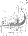
- FIG. 4 is a cross-sectional view of rotor shroud 28 positioned in cabin air compressor 10.
- FIG. 4 shows compressor inlet housing 18, compressor outlet housing 20, motor housing 22, variable diffuser 24, rotor 26, and rotor shroud 28.
- Compressor inlet housing 18 includes inlet duct 32.
- Compressor outlet housing 20 includes outlet duct 34.
- Variable diffuser 24 includes backing plate 40, inboard plate 42, diffuser vanes 44, drive ring 46, drive ring bearing 48, and backup ring 50..
- Rotor shroud 28 includes body 100 and bore 102.
- Body 100 includes first side 110, second side 112, radially inner end 114, radially outer end 116, disk portion 118, frustoconical portion 120, flared portion 122, flange 124, and bolt holes 128. As shown in FIG. 4 , body 100 further includes exterior surface 140 and lattice structure 142, which includes first region 150, second region 152, third region 154, fourth region 156, fifth region 158, sixth region 160, seventh region 162, and eighth region 164.
- Cabin air compressor 10 has the structure and design as described above in reference to FIG. 1 .
- Rotor shroud 28 has the structure and design as described above in reference to FIGS. 2A-3 .
- Rotor shroud 28 is positioned radially outward from rotor 26 and partially surrounds rotor 26.
- First side 110 of disk portion 118 of rotor shroud 28 is positioned adjacent to diffuser vanes 44.
- Second side 112 of disk portion 118 of rotor shroud 28 is positioned adjacent to drive ring 46.
- Bolts extend through backing plate 40, inboard plate 42, diffuser vanes 44, and bolt holes 128 of rotor shroud 28 to connect backing plate 40, inboard plate 42, diffuser vanes 44, and rotor shroud 28.
- Bolts extend through drive ring 46 into bolt holes 130 of rotor shroud 28 to connect rotor shroud 28 to drive ring 46.
- Frustoconical portion 120 of rotor shroud 28 is adjacent to and curves along blades of rotor 26.
- Flared portion 122 of rotor shroud 28 extends into inlet duct 32 of compressor inlet housing 18.
- Flange 124 of rotor shroud 28 has a radially outer surface that abuts drive ring bearing 48.
- Flange 124 also has grooves to receive o-rings that are positioned against and sealed against compressor inlet housing 18.
- Rotor shroud 28 has fourth region 156 of lattice structure 142 in flange 124.
- Fourth region 156 is a deflection region of rotor shroud 28, which is a region of rotor shroud 28 that is subject to deflection.
- Fourth region 156 of flange 124 is subject to deflection.
- Fourth region 156 of lattice structure 142 is an area of increased density that aids in deflection management of rotor shroud 28 to reduce and prevent deflection of rotor shroud 28.
- Rotor shroud 28 has seventh region 162 of lattice region 142 in frustoconical portion 120 adjacent radially inner end 114 and near flared portion 122.
- Seventh region 162 is a deflection region of rotor shroud 28, which is a region of frustoconical portion 120 of rotor shroud 28 that is subject to deflection.
- Seventh region 162 of frustoconical portion 120 of rotor shroud 28 can be subject to deflection.
- Seventh region 162 of lattice structure 142 is an area of increased density that aids in deflection management of rotor shroud 28 to reduce and prevent deflection of rotor shroud 28.
- Identifying deflection regions of rotor shroud 28 and increasing the density of lattice structure 142 in the deflection regions reduces and prevents the deflections and strain that rotor shroud 28 is subjected to during operation of rotor 26 by increasing the stiffness in these areas. This reduced deflection and strain and increased stiffness means that the parts deform less when in operation. If rotor shroud 28 undergoes less deflection, the gap between the blades of rotor 26 and rotor shroud 28 can be reduced. Reducing the gap increases the efficiency of cabin air compressor 10, as more air is forced through rotor 26 and into variable diffuser 24.
- Rotor shroud 28 has second region 152 of lattice region 142 in disk portion 118 surrounding bolt holes 128.
- Second region 152 is a stress region of rotor shroud 28, which is a region of rotor shroud 28 that is subject to high stress during operation of rotor shroud 28.
- the high stress in stress regions of rotor shroud 28, such as second region 152, is a higher stress than stresses present in other regions of rotor shroud 28.
- second region 152 will be subject to stress that transfers into disk portion 118 of rotor shroud 28 from the bolts extending through bolt holes 128.
- Second region 152 of lattice structure 142 is an area of increased density that aids in stress reduction during operation of cabin air compressor 10 to reduce the stress in second region 152 of rotor shroud 28. Stress reduction at critical points of rotor shroud 28 leads to increased longevity of rotor shroud 28.
- Fourth region 156 is also a stress region of rotor shroud 28, which is a region of rotor shroud 28 that is subject to high stress during operation of rotor shroud 28.
- the high stress in stress regions of rotor shroud 28, such as fourth region 156, is a higher stress than stresses present in other regions of rotor shroud 28.
- Fourth region 156 of flange 124 is subject to stress.
- Fourth region 156 of lattice structure 142 is an area of increased density that aids in stress reduction during operation of cabin air compressor 10 to reduce the stress in fourth region 156 of rotor shroud 28. Stress reduction at critical points of rotor shroud 28 leads to increased longevity of rotor shroud 28.
- Reducing stress in stress regions of rotor shroud 28 will also improve the longevity of rotor shroud 28. Reducing the stresses at stress regions can reduce the failure rate of rotor shroud 28 as well as the failure rate of cabin air compressor 10 overall. During operation, these failures can damage components surrounding rotor shroud 28, as these components are required to contain the energy of the failure for safety of the aircraft and its passengers. Reduced failure rates result in reduced down time, reduced repairs, and reduced costs.
- Rotor shroud 28 has sixth region 160 of lattice structure 142 in frustoconical portion 120 adjacent radially inner end 114 and first side 110 of body 100.
- Sixth region 160 is an energy containment region of rotor shroud 28, which is a region of rotor shroud 28 that is designed to absorb energy.
- Sixth region 160 of frustoconical portion 120 is positioned adjacent to blades on rotor 26 and needs to be designed to absorb energy from rotor 26 in the event of a failure of rotor 26.
- Sixth region 160 of lattice structure 142 is an area of increased density that aids in energy containment during operation of cabin air compressor 10. Energy containment at critical points of rotor shroud 28 ensures safe operation of cabin air compressor 10.
- rotor shroud 28 is designed to absorb the energy to protect and prevent serious damage to other components of cabin air compressor 10.
- Sixth region 160 of lattice structure 142 is positioned near rotor 26 to contain the energy from rotor 26 in rotor shroud 28.
- Rotor shroud 28 is one example of a rotor shroud in which variable lattice structure 142 can be used.
- variable lattice structure 142 can be used in any suitable rotor shroud, for example a rotor shroud for a turbine rotor, having any design.
- cabin air compressor 10 is one example of a turbomachinery or rotary machine in which rotor shroud 28 or any other rotor shroud with variable lattice structure 142 can be used.
- rotor shroud 28 or any other rotor shroud with variable lattice structure 142 can be used in an air cycle machine or any other rotary machine.
- FIG. 5 is a flowchart showing a method of manufacturing rotor shroud 28.
- FIG. 5 shows steps 200-206.
- Step 200 includes laying down a layer of powder.
- Step 202 solidifying a portion of the layer of powder.
- Step 204 includes repeating steps 200 and 202 until rotor shroud 28 is completed.
- Step 206 includes processing rotor shroud 28.
- Rotor shroud 28 can be manufactured using an additive manufacturing process.
- Additive manufacturing involves manufacturing rotor shroud 28 layer by layer. Additive manufacturing processes allow complex internal and external shapes and geometries to be manufactured that are not feasible or possible with traditional manufacturing.
- a typical additive manufacturing process involves using a computer to create a three-dimensional representation of rotor shroud 28. The three-dimensional representation will be converted into instructions which divide rotor shroud 28 into many individual layers. These instructions are then sent to an additive manufacturing device. This additive manufacturing device will print each layer, in order, and one at a time until all layers have been printed. Any additive manufacturing process can be used, including direct metal laser sintering, electron beam freeform fabrication, electron-beam melting, selective laser melting, selective laser sintering, or other equivalents that are known in the art.
- Step 200 includes laying down a layer of powder.
- the powder can be made of a material selected from the group consisting of stainless steel, corrosion-resistant steel, nickel-chromium alloy, aluminum, synthetic fiber, fiberglass, composites, and combinations thereof. This powder may be laid down by a roller, pressurized gas, or other equivalents that are known in the art. This powder may have any grain size, wherein the grain size of the powder affects the unprocessed surface properties of rotor shroud 28.
- Step 202 includes solidifying a portion of the layer of powder.
- a portion of the layer of powder can be solidified by applying energy to layer of powder. Any energy source can be used, including laser beam, electron beams, or other equivalents that are known in the art. The application of this energy will solidify the powder in a specific configuration. The specific configuration of solidified metal will be entirely dependent on which layer the process is currently at. This specific configuration will be in a specific shape and distribution so that when combined with the other layers, it forms rotor shroud 28.
- Step 204 includes repeating steps 200 and 202 until rotor shroud 28 is completed. These two steps together lead to rotor shroud 28 being built layer by layer to completion.
- the specific configuration of step 202 consists of exterior surface 140, which is continuous and solid, and lattice structure 142, which has a varying density.
- the density of lattice structure 142 can be locally optimized to reduce stress or strain in specific regions and improve energy containment in specific regions. Reducing the stresses at high stress regions can reduce the failure rate of rotor shroud 28 and thus the failure rate of cabin air compressor 10. Reduced failure rates result in reduced down time, reduced repairs, and reduced costs. Reduced strain, and thus reduced deflection, at deflection regions means that the parts deform less when in operation.
- rotor shroud 28 undergoes less deflection, the tolerances between components of cabin air compressor 10 can be reduced. Reducing tolerances between components increases the efficiency of cabin air compressor 10. Improving energy containment in energy containment regions of rotor shroud 28 ensures the safe operation of cabin air compressor 10.
- Step 206 includes processing rotor shroud 28.
- Step 206 is an optional step.
- Processing rotor shroud 28 can include post processing steps, such as smoothing of exterior surface 140 of rotor shroud 28 or removal of powder from an interior of rotor shroud 28. Since an additive manufacturing process is used, exterior surface 140 of rotor shroud 28 may be rougher than desired. Through sanding, brushing, buffing, grinding, and combinations thereof, exterior surface 140 of rotor shroud 28 may be made smoother. Removal of the powder from an interior of rotor shroud 28 can involve the process of removing the unsolidified powder between lattice structure 142 through high pressure gas, mechanical movements, or other methods know in the art.
- a rotor shroud for a rotary machine in a cabin air compressor includes a disk portion centered on a central axis of the rotor shroud, a frustoconical portion extending from the disk portion, a flared portion extending from the frustoconical portion, and a variable lattice structure in an interior of the rotor shroud.
- the variable lattice structure includes a first region of the rotor shroud having a first lattice structure and a second region of the rotor shroud having a second lattice structure.
- the second lattice structure of the second region is denser than the first lattice structure of the first region.
- the second region is a deflection region, a stress region, or an energy containment region of the rotor shroud.
- the rotor shroud of the preceding paragraph can optionally include, additionally and/or alternatively, any one or more of the following features, configurations and/or additional components:
- the rotor shroud has a continuous exterior solid surface surrounding the variable lattice structure.
- the stress region of the rotor shroud is a region of the rotor shroud that is subject to higher stress than other regions of the rotor shroud.
- the stress region of the rotor shroud is a flange extending outward from the disk portion of the rotor shroud.
- the stress region of the rotor shroud is a region of the rotor shroud surrounding a plurality of bolt holes.
- the deflection region of the rotor shroud is a region of the rotor shroud that is subject to deflections.
- the deflection region of the rotor shroud is a region of the frustoconical portion adjacent the flared portion.
- the deflection region of the rotor shroud is a flange extending outward from the disk portion of the rotor shroud.
- the energy containment region of the rotor should is a region of the rotor shroud that is configured to contain energy.
- the energy containment region of the rotor shroud is a region of the frustoconical portion adjacent a first side and a radially inner end of the rotor shroud.
- the rotor shroud is made of a material selected from the group consisting of stainless steel, corrosion-resistant steel, nickel-chromium alloy, aluminum, synthetic fiber, fiberglass, composites, and combinations thereof.
- a rotary machine includes a tie rod extending through the rotary machine, a rotor mounted on the tie rod, and a rotor shroud positioned radially outward of the rotor.
- the rotor shroud includes a disk portion centered on a central axis of the rotor shroud, a frustoconical portion extending from the disk portion, a flared portion extending from the frustoconical portion, and a variable lattice structure in an interior of the rotor shroud.
- the variable lattice structure includes a first region of the rotor shroud having a first lattice structure and a second region of the rotor shroud having a second lattice structure.
- the second lattice structure of the second region is denser than the first lattice structure of the first region.
- the second region is a deflection region, a stress region, or an energy containment region of the rotor shroud.
- the rotary machine of the preceding paragraph can optionally include, additionally and/or alternatively, any one or more of the following features, configurations and/or additional components:
- the stress region of the rotor shroud is a region of the rotor shroud that is subject to higher stress than other regions of the rotor shroud.
- the stress region of the rotor shroud is a flange extending outward from the disk portion of the rotor shroud that abuts a drive ring bearing.
- the stress region of the rotor shroud is a region of the rotor shroud surrounding a plurality of bolt holes that are configured to bolt the rotor shroud to a variable diffuser.
- the deflection region of the rotor shroud is a region of the rotor shroud that is subject to deflections.
- the deflection region of the rotor shroud is a region of the frustoconical portion adjacent the flared portion that is positioned radially outward from tips of blades on the rotor.
- the deflection region of the rotor shroud is a flange extending outward from the disk portion of the rotor shroud that abuts a drive ring bearing.
- the energy containment region of the rotor should is a region of the rotor shroud that is configured to contain energy.
- the energy containment region of the rotor shroud is a region of the frustoconical portion adjacent a first side and a radially inner end of the rotor shroud that is positioned radially outward from blades on the rotor.
Landscapes
- Engineering & Computer Science (AREA)
- Mechanical Engineering (AREA)
- General Engineering & Computer Science (AREA)
- Manufacturing & Machinery (AREA)
- Chemical & Material Sciences (AREA)
- Materials Engineering (AREA)
- Physics & Mathematics (AREA)
- Plasma & Fusion (AREA)
- Structures Of Non-Positive Displacement Pumps (AREA)
Abstract
Description
- The present disclosure relates to aircraft environmental control systems, and in particular, to a turbomachinery rotor shroud for a cabin air compressor.
- Cabin air compressors are used in environmental control systems in aircraft to condition air for delivery to an aircraft cabin. Conditioned air is air at a temperature, pressure, and humidity desirable for aircraft passenger comfort and safety. At or near ground level, the ambient air temperature and humidity is often sufficiently high that the air must be cooled as part of the conditioning process before being delivered to the aircraft cabin. At flight altitude, ambient air is often far cooler than desired, but at such a low pressure that it must be compressed to an acceptable pressure as part of the conditioning process. Compressing ambient air at flight altitude heats the resulting pressurized air sufficiently that it must be cooled, even if the ambient air temperature is very low. Thus, under most conditions, heat must be removed from the air by the air cycle machine before the air is delivered to the aircraft cabin.
- A cabin air compressor can be used to compress air for use in an environmental control system. The cabin air compressor includes a motor to drive a compressor section that in turn compresses air flowing through the cabin air compressor. This compressor section includes a rotor, which transfers rotational energy from the motor to a fluid. The rotor is surrounded by a rotor shroud which improves rotor efficiency and protects the surrounding components in case of rotor failure.
- A rotor shroud for a rotary machine in a cabin air compressor includes a disk portion centered on a central axis of the rotor shroud, a frustoconical portion extending from the disk portion, a flared portion extending from the frustoconical portion, and a variable lattice structure in an interior of the rotor shroud. The variable lattice structure includes a first region of the rotor shroud having a first lattice structure and a second region of the rotor shroud having a second lattice structure. The second lattice structure of the second region is denser than the first lattice structure of the first region. The second region is a deflection region, a stress region, or an energy containment region of the rotor shroud.
- A rotary machine includes a tie rod extending through the rotary machine, a rotor mounted on the tie rod, and a rotor shroud positioned radially outward of the rotor. The rotor shroud includes a disk portion centered on a central axis of the rotor shroud, a frustoconical portion extending from the disk portion, a flared portion extending from the frustoconical portion, and a variable lattice structure in an interior of the rotor shroud. The variable lattice structure includes a first region of the rotor shroud having a first lattice structure and a second region of the rotor shroud having a second lattice structure. The second lattice structure of the second region is denser than the first lattice structure of the first region. The second region is a deflection region, a stress region, or an energy containment region of the rotor shroud.
-
-
FIG. 1 is cross-sectional view of a cabin air compressor. -
FIG. 2A is a perspective view of a first side of a rotor shroud of the cabin air compressor. -
FIG. 2B is a perspective view of a second side of the rotor shroud of the cabin air compressor. -
FIG. 3 is a cross-sectional view of the rotor shroud taken along section line 3-3 ofFIG. 2A . -
FIG. 4 is a cross-sectional view of the rotor shroud positioned in the cabin air compressor. -
FIG. 5 is a flowchart showing a method of manufacturing the rotor shroud. -
FIG. 1 is a cross-sectional view ofcabin air compressor 10.Cabin air compressor 10 includescompressor section 12,motor section 14,tie rod 16,compressor inlet housing 18,compressor outlet housing 20,motor housing 22,variable diffuser 24,rotor 26, androtor shroud 28.Compressor inlet housing 18 includesinlet 30 andinlet duct 32.Compressor outlet housing 20 includesoutlet duct 34 andoutlet 36.Variable diffuser 16 includesbacking plate 40,inboard plate 42,diffuser vanes 44,drive ring 46, drive ring bearing 48,backup ring 50,pinion 52, andvariable diffuser actuator 54.Motor section 14 includesmotor rotor 60 andmotor stator 62.Cabin air compressor 10 further includes first journal bearing 70, first rotatingshaft 72, second journal bearing 74, and second rotatingshaft 76.FIG. 1 also shows axis A. -
Cabin air compressor 10 includescompressor section 12 andmotor section 14 mounted ontie rod 16.Tie rod 16 is configured to rotate about axisA. Compressor section 12 includescompressor inlet housing 18 andcompressor outlet housing 20 that are connected to one another.Motor section 14 includesmotor housing 22, which is connected tocompressor outlet housing 20.Variable diffuser 24 is positioned betweencompressor inlet housing 18 andcompressor outlet housing 20.Rotor 26 is positioned betweencompressor inlet housing 18 andcompressor outlet housing 20.Rotor 26 is mounted ontie rod 16, which rotatably connectsrotor 26 andmotor section 14.Rotor shroud 28 is positioned radially outward from and partially surroundscompressor rotor 26. -
Compressor inlet housing 18 includesinlet 30 andinlet duct 32.Inlet 30 is positioned at a first end ofcompressor inlet housing 18.Inlet duct 32 extends frominlet 30 throughcompressor inlet housing 18 torotor 26.Compressor outlet housing 20 includesoutlet duct 34 andoutlet 36.Outlet duct 34 extends throughcompressor outlet housing 20 fromrotor 26 tooutlet 36. -
Variable diffuser 16 includesbacking plate 40,inboard plate 42,diffuser vanes 44,drive ring 46, drive ring bearing 48,pinion 50,backup ring 52, andvariable diffuser actuator 54.Backing plate 40 abuts compressor outlet housing 20 on a first side andinboard plate 42 on a second side.Inboard plate 42abuts backing plate 40 on a first side anddiffuser vanes 44 on a second side. Diffuser vanes 44 abutinboard plate 42 on a first side androtor shroud 28 on a second side.Diffuser vanes 44 are configured to direct the compressed air fromrotor 26 intooutlet duct 34.Drive ring 46 is positioned radially outward fromrotor shroud 28, and drive ring bearing 48 is positioned betweendriver ring 46 androtor shroud 28. Drivering 46abuts rotor shroud 28 on a first side and backupring 50 on a second side.Backup ring 50 is positioned radially outward ofrotor shroud 28. Pinion 52 is connected tovariable diffuser actuator 54 and is coupled to drivering 46. Pinion 52 permits control ofvariable diffuser 16.Drive ring 46 is coupled todiffuser vanes 44 with pins, and asdrive ring 46 is rotated it will dragdiffuser vanes 44 and cause them to rotate. -
Motor section 14 includesmotor housing 22,motor rotor 60, andmotor stator 62.Motor housing 22 surroundsmotor rotor 60 andmotor stator 62.Motor rotor 60 is disposed withinmotor stator 62 and is configured to rotate about axisA. Motor rotor 60 is mounted totie rod 16 to drive rotation oftie rod 16. -
Motor rotor 60 ofmotor section 14 drives rotation of shafts incabin air compressor 10, which in turn rotaterotor 26. The rotation ofrotor 26 draws air intoinlet 30 ofcompressor inlet housing 18. The air flows throughinlet duct 32 torotor 26 and will be compressed byrotor 26. The compressed air is then routed throughvariable diffuser 16 and intooutlet duct 34 ofcompressor outlet housing 20. The air then exitscabin air compressor 10 throughoutlet 36 ofcompressor outlet housing 20 and can be routed to another component of an environmental control system, such as an air cycle machine. -
Cabin air compressor 10 further includes first journal bearing 70, firstrotating shaft 72, second journal bearing 74, and secondrotating shaft 76. First journal bearing 70 is positioned incompressor section 12 and is supported bycompressor outlet housing 20. First rotatingshaft 72 extends between and rotates withrotor 26 andmotor rotor 60.Motor rotor 60 drives rotation ofrotor 26 with firstrotating shaft 72. A radially outer surface of firstrotating shaft 72 abuts a radially inner surface of first journal bearing 70. Second journal bearing 74 is positioned inmotor section 14 and is supported bymotor housing 22. Second rotatingshaft 76 extends from and rotates withmotor rotor 60. A radially outer surface of secondrotating shaft 76 abuts a radially inner surface of second journal bearing 74. -
FIG. 2A is a perspective view of a first side ofrotor shroud 28 ofcabin air compressor 10.FIG. 2B is a perspective view of a second side ofrotor shroud 28 ofcabin air compressor 10.FIG. 3 is a cross-sectional view of the rotor shroud taken along the section line 3-3 ofFIG. 2A .FIGS. 2A-3 will be discussed together.Rotor shroud 28 includesbody 100 and bore 102.Body 100 includesfirst side 110,second side 112, radiallyinner end 114, radiallyouter end 116,disk portion 118,frustoconical portion 120, flaredportion 122, flange 124 (shown inFIGS. 2B-3 ), openings 126 (shown inFIGS. 2A-2B ), bolt holes 128, and bolt holes 130. As shown inFIG. 3 ,body 100 further includesexterior surface 140 andlattice structure 142, which includesfirst region 150,second region 152,third region 154,fourth region 156,fifth region 158,sixth region 160,seventh region 162, andeighth region 164. -
Rotor shroud 28 includesbody 100 withbore 102 extending through a center ofbody 100.Body 100 hasfirst side 110 andsecond side 112 opposite offirst side 110.Body 100 also has radiallyinner end 114 and radiallyouter end 116 opposite of radiallyinner end 114. Radiallyinner end 114 ofbody 100 defines bore 102 extending throughbody 100 ofrotor shroud 28. -
Body 100 includesdisk portion 118 extending from radiallyouter end 116 tofrustoconical portion 120.Disk portion 118 is a generally flat portion ofbody 100.Frustoconical portion 120 extends fromdisk portion 118 to flaredportion 122.Frustoconical portion 120 has a generally frustoconical shape with a wider portion that tapers to a narrower portion radially inwards towards radiallyinner end 114 and axially outwards towardssecond side 112. Flaredportion 122 extends fromfrustoconical portion 120 tosecond side 112. Flaredportion 122 has a narrower portion adjacentfrustoconical portion 120 and flares radially outward towards radiallyouter end 116. -
Flange 124 is adjacent to a radially inner end ofdisk portion 118 and extends axially away fromdisk portion 118 towardssecond side 112.Flange 124 includes grooves that are configured to receive o-rings to seal against other components ofcabin air compressor 10.Openings 126 include a plurality of openings positioned around a radially outer end ofdisk portion 118 and extend fromfirst side 110 tosecond side 112 ofdisk portion 118. Bolt holes 128 include a plurality of holes positioned arounddisk portion 118 radially inward fromopenings 126. Bolt holes 128 extend fromfirst side 110 tosecond side 112 ofdisk portion 118. Bolt holes 130 includes a plurality of holes positioned arounddisk portion 118 radially inward from bolt holes 128. Bolt holes 130 extend fromfirst side 110 tosecond side 112 ofdisk portion 118. -
Body 100 further includesexterior surface 140 that surroundslattice structure 142 in an interior ofbody 100.Exterior surface 140 is a solid, continuous surface.Lattice structure 142 is a varying lattice structure.Lattice structure 142 has regions with varying densities. As shown inFIG. 3 ,lattice structure 142 hasfirst region 150,second region 152,third region 154,fourth region 156,fifth region 158,sixth region 160,seventh region 162, andeighth region 164.Lattice structure 142 may vary gradually or abruptly between regions.Lattice structure 142 includes members arranged in a 3D crisscrossing pattern with voids between the members. As shown inFIG. 3 ,lattice structure 142 varies in density by having a varying distribution of the members and voids oflattice structure 142. In alternate embodiments,lattice structure 142 can vary in density by varying the thickness of the members, by having varying geometrical configurations, and/or by varying fillet radii on joints between the members. -
First region 150 is a region oflattice structure 142 indisk portion 118 adjacent radiallyouter end 116.Second region 152 is a region oflattice structure 142 indisk portion 118 surrounding bolt holes 128.Third region 154 is a region oflattice structure 142 indisk portion 118 radially inward of bolt holes 128 and extending throughfrustoconical portion 120.Fourth region 156 is a region oflattice structure 142 inflange 124 extending fromdisk portion 118.Fifth region 158 is a region oflattice structure 142 inflange 124 at a second side offlange 124.Sixth region 160 is a region oflattice structure 142 infrustoconical portion 120 adjacent radiallyinner end 114 andfirst side 110 ofbody 100.Seventh region 162 is a region oflattice structure 142 infrustoconical portion 120 adjacent radiallyinner end 114 and near flaredportion 122.Eighth region 164 is a region oflattice structure 142 extending fromfrustoconical portion 120 and through flaredportion 122. - In the embodiment shown in
FIG. 3 ,second region 152,fourth region 156,sixth region 160, andseventh region 162 have a greater density thanfirst region 150,third region 154,fifth region 158, andeighth region 164.Rotor shroud 28 is additively manufactured, allowinglattice structure 142 to be manufactured with different densities in different areas ofrotor shroud 28. Any suitable additive manufacturing process (also known as a 3D printing process) can be used to manufacturerotor shroud 28, including, for example, direct metal laser sintering, electron beam freeform fabrication, electron-beam melting, selective laser melting, or selective laser sintering.Rotor shroud 28 can be made out of any material that can be used in an additive manufacturing process, including any of stainless steel, corrosion-resistant steel, nickel-chromium alloy, aluminum, synthetic fiber, fiberglass, composites, and combinations thereof. - Traditional rotor shrouds for rotary machines have solid cross-sections and are manufactured by casting and/or subtractive manufacturing processes, such as hogout. Additively
manufacturing rotor shroud 28 allowslattice structure 142 to be used inrotor shroud 28. Usinglattice structure 142 inrotor shroud 28 allowsrotor shroud 28 to have a reduced weight compared to traditional rotor shrouds, as there are voids between the lattice structure. At the same time,rotor shroud 28 will have an equivalent strength as traditional rotor shrouds due to the increased strength oflattice structure 142. - Further, the density of
lattice structure 142 is varied to optimize mechanical properties ofrotor shroud 28 locally and generally. Mechanical properties ofrotor shroud 28, such as stress, strain, stiffness, and energy absorption, can be optimized to improve the performance ofrotor shroud 28 by reducing stress in high stress regions ofrotor shroud 28, reducing strain and increasing stiffness in deflection regions ofrotor shroud 28, and increasing energy absorption capacity at energy containment regions ofrotor shroud 28. Reducing stress and strain in local regions ofrotor shroud 28 can also reduce stress and strain inrotor shroud 28 generally. Reducing the stresses in high stress regions can reduce the failure rate of components incabin air compressor 10. Reduced failure rates result in reduced down time, reduced repairs, and reduced costs. Reducing the strain and increasing the stiffness in deflection regions can reduce the tolerances between blades ofrotor 26 androtor shroud 28. Reducing the tolerances between the blades ofrotor 26 androtor shroud 28 can increase the compression efficiency ofcabin air compressor 10, as more air is forced throughrotor 26 and intovariable diffuser 24. Increased energy absorption capacity can improve the safe operation ofcabin air compressor 10. Shouldrotor 26 fail,rotor shroud 26,compressor outlet housing 20, and other components incabin air compressor 10 can contain this energy to protect other components ofcabin air compressor 10. -
FIG. 4 is a cross-sectional view ofrotor shroud 28 positioned incabin air compressor 10.FIG. 4 showscompressor inlet housing 18,compressor outlet housing 20,motor housing 22,variable diffuser 24,rotor 26, androtor shroud 28.Compressor inlet housing 18 includesinlet duct 32.Compressor outlet housing 20 includesoutlet duct 34.Variable diffuser 24 includes backingplate 40, inboardplate 42,diffuser vanes 44,drive ring 46, drive ring bearing 48, andbackup ring 50..Rotor shroud 28 includesbody 100 and bore 102.Body 100 includesfirst side 110,second side 112, radiallyinner end 114, radiallyouter end 116,disk portion 118,frustoconical portion 120, flaredportion 122,flange 124, and bolt holes 128. As shown inFIG. 4 ,body 100 further includesexterior surface 140 andlattice structure 142, which includesfirst region 150,second region 152,third region 154,fourth region 156,fifth region 158,sixth region 160,seventh region 162, andeighth region 164. -
Cabin air compressor 10 has the structure and design as described above in reference toFIG. 1 .Rotor shroud 28 has the structure and design as described above in reference toFIGS. 2A-3 .Rotor shroud 28 is positioned radially outward fromrotor 26 and partially surroundsrotor 26.First side 110 ofdisk portion 118 ofrotor shroud 28 is positioned adjacent todiffuser vanes 44.Second side 112 ofdisk portion 118 ofrotor shroud 28 is positioned adjacent to drivering 46. Bolts extend throughbacking plate 40, inboardplate 42,diffuser vanes 44, and boltholes 128 ofrotor shroud 28 to connectbacking plate 40, inboardplate 42,diffuser vanes 44, androtor shroud 28. Bolts extend throughdrive ring 46 intobolt holes 130 ofrotor shroud 28 to connectrotor shroud 28 to drivering 46.Frustoconical portion 120 ofrotor shroud 28 is adjacent to and curves along blades ofrotor 26. Flaredportion 122 ofrotor shroud 28 extends intoinlet duct 32 ofcompressor inlet housing 18.Flange 124 ofrotor shroud 28 has a radially outer surface that abuts drive ring bearing 48.Flange 124 also has grooves to receive o-rings that are positioned against and sealed againstcompressor inlet housing 18. -
Rotor shroud 28 hasfourth region 156 oflattice structure 142 inflange 124.Fourth region 156 is a deflection region ofrotor shroud 28, which is a region ofrotor shroud 28 that is subject to deflection. Asdrive ring 46 rotates against drive ring bearing 48,fourth region 156 offlange 124 is subject to deflection.Fourth region 156 oflattice structure 142 is an area of increased density that aids in deflection management ofrotor shroud 28 to reduce and prevent deflection ofrotor shroud 28. By reducing and preventing deflection ofrotor shroud 28, the efficiency ofcabin air compressor 10 can be increased. -
Rotor shroud 28 hasseventh region 162 oflattice region 142 infrustoconical portion 120 adjacent radiallyinner end 114 and near flaredportion 122.Seventh region 162 is a deflection region ofrotor shroud 28, which is a region offrustoconical portion 120 ofrotor shroud 28 that is subject to deflection. Asrotor 26 rotates,seventh region 162 offrustoconical portion 120 ofrotor shroud 28 can be subject to deflection.Seventh region 162 oflattice structure 142 is an area of increased density that aids in deflection management ofrotor shroud 28 to reduce and prevent deflection ofrotor shroud 28. By reducing and preventing deflection ofrotor shroud 28, the efficiency ofcabin air compressor 10 can be increased. - There is a gap between blades of
rotor 26 androtor shroud 28 to prevent contact between the blades ofrotor 26 androtor shroud 28. Contact between the blades androtor shroud 28 may damage both components and cause failure ofcabin air compressor 10. The gap between the blades ofrotor 26 androtor shroud 28 has to account for deflection thatrotor 26 androtor shroud 28 can be subjected to during operation ofrotor 26. Thus, the more deformation thatrotor 26 androtor shroud 28 are subjected to during operation ofrotor 26, the larger the gap needs to be to ensure component safety. However, air can leak fromcabin air compressor 10 through the gap, which leads to inefficiencies incabin air compressor 10. Thus, it is desirable to minimize the gap between the blades ofrotor 26 androtor shroud 28. Identifying deflection regions ofrotor shroud 28 and increasing the density oflattice structure 142 in the deflection regions (for example,fourth region 156 and seventh region 162) reduces and prevents the deflections and strain thatrotor shroud 28 is subjected to during operation ofrotor 26 by increasing the stiffness in these areas. This reduced deflection and strain and increased stiffness means that the parts deform less when in operation. Ifrotor shroud 28 undergoes less deflection, the gap between the blades ofrotor 26 androtor shroud 28 can be reduced. Reducing the gap increases the efficiency ofcabin air compressor 10, as more air is forced throughrotor 26 and intovariable diffuser 24. -
Rotor shroud 28 hassecond region 152 oflattice region 142 indisk portion 118 surrounding bolt holes 128.Second region 152 is a stress region ofrotor shroud 28, which is a region ofrotor shroud 28 that is subject to high stress during operation ofrotor shroud 28. The high stress in stress regions ofrotor shroud 28, such assecond region 152, is a higher stress than stresses present in other regions ofrotor shroud 28. During operation ofvariable diffuser 24,second region 152 will be subject to stress that transfers intodisk portion 118 ofrotor shroud 28 from the bolts extending through bolt holes 128.Second region 152 oflattice structure 142 is an area of increased density that aids in stress reduction during operation ofcabin air compressor 10 to reduce the stress insecond region 152 ofrotor shroud 28. Stress reduction at critical points ofrotor shroud 28 leads to increased longevity ofrotor shroud 28. -
Fourth region 156 is also a stress region ofrotor shroud 28, which is a region ofrotor shroud 28 that is subject to high stress during operation ofrotor shroud 28. The high stress in stress regions ofrotor shroud 28, such asfourth region 156, is a higher stress than stresses present in other regions ofrotor shroud 28. Asdrive ring 46 rotates against drive ring bearing 48,fourth region 156 offlange 124 is subject to stress.Fourth region 156 oflattice structure 142 is an area of increased density that aids in stress reduction during operation ofcabin air compressor 10 to reduce the stress infourth region 156 ofrotor shroud 28. Stress reduction at critical points ofrotor shroud 28 leads to increased longevity ofrotor shroud 28. - Reducing stress in stress regions of
rotor shroud 28 will also improve the longevity ofrotor shroud 28. Reducing the stresses at stress regions can reduce the failure rate ofrotor shroud 28 as well as the failure rate ofcabin air compressor 10 overall. During operation, these failures can damage components surroundingrotor shroud 28, as these components are required to contain the energy of the failure for safety of the aircraft and its passengers. Reduced failure rates result in reduced down time, reduced repairs, and reduced costs. -
Rotor shroud 28 hassixth region 160 oflattice structure 142 infrustoconical portion 120 adjacent radiallyinner end 114 andfirst side 110 ofbody 100.Sixth region 160 is an energy containment region ofrotor shroud 28, which is a region ofrotor shroud 28 that is designed to absorb energy.Sixth region 160 offrustoconical portion 120 is positioned adjacent to blades onrotor 26 and needs to be designed to absorb energy fromrotor 26 in the event of a failure ofrotor 26.Sixth region 160 oflattice structure 142 is an area of increased density that aids in energy containment during operation ofcabin air compressor 10. Energy containment at critical points ofrotor shroud 28 ensures safe operation ofcabin air compressor 10. - Increased energy containment is important to the safe operation of
cabin air compressor 10. Ifrotor 26 fails,rotor shroud 28 is designed to absorb the energy to protect and prevent serious damage to other components ofcabin air compressor 10.Sixth region 160 oflattice structure 142 is positioned nearrotor 26 to contain the energy fromrotor 26 inrotor shroud 28. -
Rotor shroud 28 is one example of a rotor shroud in whichvariable lattice structure 142 can be used. In alternate embodiments,variable lattice structure 142 can be used in any suitable rotor shroud, for example a rotor shroud for a turbine rotor, having any design. Further,cabin air compressor 10 is one example of a turbomachinery or rotary machine in whichrotor shroud 28 or any other rotor shroud withvariable lattice structure 142 can be used. In alternate embodiments,rotor shroud 28 or any other rotor shroud withvariable lattice structure 142 can be used in an air cycle machine or any other rotary machine. -
FIG. 5 is a flowchart showing a method ofmanufacturing rotor shroud 28.FIG. 5 shows steps 200-206. Step 200 includes laying down a layer of powder. Step 202 solidifying a portion of the layer of powder. Step 204 includes repeatingsteps rotor shroud 28 is completed. Step 206 includesprocessing rotor shroud 28. -
Rotor shroud 28 can be manufactured using an additive manufacturing process. Additive manufacturing involvesmanufacturing rotor shroud 28 layer by layer. Additive manufacturing processes allow complex internal and external shapes and geometries to be manufactured that are not feasible or possible with traditional manufacturing. A typical additive manufacturing process involves using a computer to create a three-dimensional representation ofrotor shroud 28. The three-dimensional representation will be converted into instructions which dividerotor shroud 28 into many individual layers. These instructions are then sent to an additive manufacturing device. This additive manufacturing device will print each layer, in order, and one at a time until all layers have been printed. Any additive manufacturing process can be used, including direct metal laser sintering, electron beam freeform fabrication, electron-beam melting, selective laser melting, selective laser sintering, or other equivalents that are known in the art. - Step 200 includes laying down a layer of powder. The powder can be made of a material selected from the group consisting of stainless steel, corrosion-resistant steel, nickel-chromium alloy, aluminum, synthetic fiber, fiberglass, composites, and combinations thereof. This powder may be laid down by a roller, pressurized gas, or other equivalents that are known in the art. This powder may have any grain size, wherein the grain size of the powder affects the unprocessed surface properties of
rotor shroud 28. - Step 202 includes solidifying a portion of the layer of powder. A portion of the layer of powder can be solidified by applying energy to layer of powder. Any energy source can be used, including laser beam, electron beams, or other equivalents that are known in the art. The application of this energy will solidify the powder in a specific configuration. The specific configuration of solidified metal will be entirely dependent on which layer the process is currently at. This specific configuration will be in a specific shape and distribution so that when combined with the other layers, it forms
rotor shroud 28. - Step 204 includes repeating
steps rotor shroud 28 is completed. These two steps together lead torotor shroud 28 being built layer by layer to completion. The specific configuration ofstep 202 consists ofexterior surface 140, which is continuous and solid, andlattice structure 142, which has a varying density. The density oflattice structure 142 can be locally optimized to reduce stress or strain in specific regions and improve energy containment in specific regions. Reducing the stresses at high stress regions can reduce the failure rate ofrotor shroud 28 and thus the failure rate ofcabin air compressor 10. Reduced failure rates result in reduced down time, reduced repairs, and reduced costs. Reduced strain, and thus reduced deflection, at deflection regions means that the parts deform less when in operation. Ifrotor shroud 28 undergoes less deflection, the tolerances between components ofcabin air compressor 10 can be reduced. Reducing tolerances between components increases the efficiency ofcabin air compressor 10. Improving energy containment in energy containment regions ofrotor shroud 28 ensures the safe operation ofcabin air compressor 10. - Step 206 includes
processing rotor shroud 28. Step 206 is an optional step. Processingrotor shroud 28 can include post processing steps, such as smoothing ofexterior surface 140 ofrotor shroud 28 or removal of powder from an interior ofrotor shroud 28. Since an additive manufacturing process is used,exterior surface 140 ofrotor shroud 28 may be rougher than desired. Through sanding, brushing, buffing, grinding, and combinations thereof,exterior surface 140 ofrotor shroud 28 may be made smoother. Removal of the powder from an interior ofrotor shroud 28 can involve the process of removing the unsolidified powder betweenlattice structure 142 through high pressure gas, mechanical movements, or other methods know in the art. - The following are non-exclusive descriptions of possible embodiments of the present invention.
- A rotor shroud for a rotary machine in a cabin air compressor includes a disk portion centered on a central axis of the rotor shroud, a frustoconical portion extending from the disk portion, a flared portion extending from the frustoconical portion, and a variable lattice structure in an interior of the rotor shroud. The variable lattice structure includes a first region of the rotor shroud having a first lattice structure and a second region of the rotor shroud having a second lattice structure. The second lattice structure of the second region is denser than the first lattice structure of the first region. The second region is a deflection region, a stress region, or an energy containment region of the rotor shroud.
- The rotor shroud of the preceding paragraph can optionally include, additionally and/or alternatively, any one or more of the following features, configurations and/or additional components:
- The rotor shroud has a continuous exterior solid surface surrounding the variable lattice structure.
- The stress region of the rotor shroud is a region of the rotor shroud that is subject to higher stress than other regions of the rotor shroud.
- The stress region of the rotor shroud is a flange extending outward from the disk portion of the rotor shroud.
- The stress region of the rotor shroud is a region of the rotor shroud surrounding a plurality of bolt holes.
- The deflection region of the rotor shroud is a region of the rotor shroud that is subject to deflections.
- The deflection region of the rotor shroud is a region of the frustoconical portion adjacent the flared portion.
- The deflection region of the rotor shroud is a flange extending outward from the disk portion of the rotor shroud.
- The energy containment region of the rotor should is a region of the rotor shroud that is configured to contain energy.
- The energy containment region of the rotor shroud is a region of the frustoconical portion adjacent a first side and a radially inner end of the rotor shroud.
- The rotor shroud is made of a material selected from the group consisting of stainless steel, corrosion-resistant steel, nickel-chromium alloy, aluminum, synthetic fiber, fiberglass, composites, and combinations thereof.
- A rotary machine includes a tie rod extending through the rotary machine, a rotor mounted on the tie rod, and a rotor shroud positioned radially outward of the rotor. The rotor shroud includes a disk portion centered on a central axis of the rotor shroud, a frustoconical portion extending from the disk portion, a flared portion extending from the frustoconical portion, and a variable lattice structure in an interior of the rotor shroud. The variable lattice structure includes a first region of the rotor shroud having a first lattice structure and a second region of the rotor shroud having a second lattice structure. The second lattice structure of the second region is denser than the first lattice structure of the first region. The second region is a deflection region, a stress region, or an energy containment region of the rotor shroud.
- The rotary machine of the preceding paragraph can optionally include, additionally and/or alternatively, any one or more of the following features, configurations and/or additional components:
- The stress region of the rotor shroud is a region of the rotor shroud that is subject to higher stress than other regions of the rotor shroud.
- The stress region of the rotor shroud is a flange extending outward from the disk portion of the rotor shroud that abuts a drive ring bearing.
- The stress region of the rotor shroud is a region of the rotor shroud surrounding a plurality of bolt holes that are configured to bolt the rotor shroud to a variable diffuser.
- The deflection region of the rotor shroud is a region of the rotor shroud that is subject to deflections.
- The deflection region of the rotor shroud is a region of the frustoconical portion adjacent the flared portion that is positioned radially outward from tips of blades on the rotor.
- The deflection region of the rotor shroud is a flange extending outward from the disk portion of the rotor shroud that abuts a drive ring bearing.
- The energy containment region of the rotor should is a region of the rotor shroud that is configured to contain energy.
- The energy containment region of the rotor shroud is a region of the frustoconical portion adjacent a first side and a radially inner end of the rotor shroud that is positioned radially outward from blades on the rotor.
- While the invention has been described with reference to an exemplary embodiment(s), it will be understood by those skilled in the art that various changes may be made and equivalents may be substituted for elements thereof without departing from the scope of the invention. In addition, many modifications may be made to adapt a particular situation or material to the teachings of the invention without departing from the essential scope thereof. Therefore, it is intended that the invention not be limited to the particular embodiment(s) disclosed, but that the invention will include all embodiments falling within the scope of the appended claims.
Claims (15)
- A rotor shroud (28) for a rotary machine comprising:a disk portion (118) centered on a central axis of the rotor shroud;a frustoconical portion (120) extending from the disk portion (118);a flared portion (122) extending from the frustoconical portion (120); anda variable lattice structure (142) in an interior of the rotor shroud, the variable lattice structure (142) comprises:a first region (150) of the rotor shroud having a first lattice structure; anda second region (152) of the rotor shroud having a second lattice structure;wherein the second lattice structure of the second region (152) is denser than the first lattice structure of the first region (150); andwherein the second region (152) is a deflection region, a stress region, or an energy containment region of the rotor shroud (28).
- The rotor shroud of claim 1, wherein the rotor shroud (28) has a continuous exterior solid surface (140) surrounding the variable lattice structure.
- The rotor shroud of claim 1, wherein the stress region of the rotor shroud is a region of the rotor shroud that is subject to higher stress than other regions of the rotor shroud.
- The rotor shroud of claim 3, wherein the stress region of the rotor shroud is a flange (124) extending outward from the disk portion (118) of the rotor shroud.
- The rotor shroud of claim 3, wherein the stress region of the rotor shroud is a region of the rotor shroud surrounding a plurality of bolt holes (130).
- The rotor shroud of claim 1, wherein the deflection region of the rotor shroud is a region of the rotor shroud that is subject to deflections.
- The rotor shroud of claim 6, wherein the deflection region of the rotor shroud is a region of the frustoconical portion (120) adjacent the flared portion (122).
- The rotor shroud of claim 6, wherein the deflection region of the rotor shroud is a flange (124) extending outward from the disk portion (118) of the rotor shroud.
- The rotor shroud of claim 1, wherein the energy containment region of the rotor should is a region of the rotor shroud that is configured to contain energy.
- The rotor shroud of claim 9, wherein the energy containment region of the rotor shroud is a region of the frustoconical portion (120) adjacent a first side and a radially inner end (114) of the rotor shroud (28).
- The rotor shroud of any preceding claim, wherein the rotor shroud (28) is made of a material selected from the group consisting of stainless steel, corrosion-resistant steel, nickel-chromium alloy, aluminum, synthetic fiber, fiberglass, composites, and combinations thereof.
- A rotary machine comprising:a tie rod (16) extending through the rotary machine;a rotor (26) mounted on the tie rod (16); anda rotor shroud (28), as claimed in any preceding claim, positioned radially outward of the rotor (26).
- The rotary machine of claim 12, when dependent on claim 5, wherein the plurality of bolt holes (130) are configured to bolt the rotor shroud to a variable diffuser (16).
- The rotary machine of claim 12, when dependent on claim 7, wherein the flared portion (120) is positioned radially outward from tips of blades on the rotor (26).
- The rotary machine of claim 12, when dependent on claim 8, wherein the deflection region abuts a drive ring bearing (48).
Applications Claiming Priority (1)
| Application Number | Priority Date | Filing Date | Title |
|---|---|---|---|
| US17/472,134 US11773746B2 (en) | 2021-09-10 | 2021-09-10 | Turbomachinery rotor shroud with variable lattice densities |
Publications (1)
| Publication Number | Publication Date |
|---|---|
| EP4148285A1 true EP4148285A1 (en) | 2023-03-15 |
Family
ID=83193294
Family Applications (1)
| Application Number | Title | Priority Date | Filing Date |
|---|---|---|---|
| EP22193978.8A Pending EP4148285A1 (en) | 2021-09-10 | 2022-09-05 | Turbomachinery rotor shroud with variable lattice densities |
Country Status (2)
| Country | Link |
|---|---|
| US (1) | US11773746B2 (en) |
| EP (1) | EP4148285A1 (en) |
Cited By (2)
| Publication number | Priority date | Publication date | Assignee | Title |
|---|---|---|---|---|
| US20260028126A1 (en) * | 2024-07-29 | 2026-01-29 | Hamilton Sundstrand Corporation | Additively manufactured heat exchanger and diffuser pipe coupled to a compressor stage |
| FR3165240A1 (en) * | 2024-08-01 | 2026-02-06 | Safran Additive Manufacturing Campus | AIRCRAFT PART AND ITS MANUFACTURING PROCESS |
Families Citing this family (1)
| Publication number | Priority date | Publication date | Assignee | Title |
|---|---|---|---|---|
| FR3148625A1 (en) * | 2023-05-12 | 2024-11-15 | Arianegroup Sas | Housing for rotating machine |
Citations (4)
| Publication number | Priority date | Publication date | Assignee | Title |
|---|---|---|---|---|
| US8777561B2 (en) * | 2010-11-05 | 2014-07-15 | Hamilton Sundstrand Corporation | Compressor shroud having a retention cover channel for receiving a retention cover |
| US20210025325A1 (en) * | 2019-07-23 | 2021-01-28 | Transportation Ip Holdings, Llc | System for a combined turbine, compressor, shroud, and bearing case for a turbocharger |
| US20210025405A1 (en) * | 2019-07-23 | 2021-01-28 | Ge Global Sourcing Llc | System for a combined turbine and bearing case for a turbocharger |
| US20210156304A1 (en) * | 2019-11-25 | 2021-05-27 | Transportation Ip Holdings, Llc | Case-integrated turbomachine wheel containment |
Family Cites Families (60)
| Publication number | Priority date | Publication date | Assignee | Title |
|---|---|---|---|---|
| NO134668C (en) | 1975-02-20 | 1976-11-24 | Kongsberg Vapenfab As | |
| JPS6186211A (en) | 1984-10-04 | 1986-05-01 | 日本碍子株式会社 | Ceramics composite structure and manufacture thereof |
| US5224842A (en) | 1992-01-10 | 1993-07-06 | Dziorny Paul J | Air cycle machine with interstage venting |
| US20030005705A1 (en) | 2001-07-05 | 2003-01-09 | Honeywell International, Inc. | Industrial gas turbine multi-axial thermal isolator |
| DE10253299B4 (en) | 2002-11-15 | 2004-09-30 | Daimlerchrysler Ag | Wheel |
| US7140839B2 (en) | 2004-09-22 | 2006-11-28 | Hamilton Sundstrand | Variable area diffuser vane geometry |
| GB0510538D0 (en) * | 2005-05-24 | 2005-06-29 | Rolls Royce Plc | A rotor blade containment assembly for a gas turbine engine |
| EP1985801A1 (en) | 2007-04-23 | 2008-10-29 | Siemens Aktiengesellschaft | Impeller coating |
| EP2312171A3 (en) | 2009-10-13 | 2014-05-07 | Franz Mitsch | Method for reducing and preventing material fatigue in rotating shafts exposed to bending stresses |
| FR2958353B1 (en) | 2010-03-30 | 2013-04-05 | Peugeot Citroen Automobiles Sa | GEARBOX, ESPECIALLY FOR A MOTOR VEHICLE, AND A TREE OR TREES FOR SUCH A GEARBOX AND METHOD OF MANUFACTURING SUCH TREES |
| US8529192B2 (en) | 2010-09-15 | 2013-09-10 | Hamilton Sundstrand Corporation | Thrust bearing shaft for thrust and journal air bearing cooling in a compressor |
| US8932021B2 (en) | 2010-12-21 | 2015-01-13 | Hamilton Sundstrand Corporation | Fan rotor for air cycle machine |
| ITFI20120035A1 (en) | 2012-02-23 | 2013-08-24 | Nuovo Pignone Srl | "IMPELLER PRODUCTION FOR TURBO-MACHINES" |
| EP2819794B1 (en) | 2012-02-27 | 2019-08-21 | SchmitterGroup AG | Hollow drive shaft with flange and method for the production thereof |
| US20140026993A1 (en) | 2012-07-30 | 2014-01-30 | Hamilton Sundstrand Corporation | Cabin air compressor heat housing |
| US9181959B2 (en) | 2012-08-07 | 2015-11-10 | Hamilton Sundstrand Corporation | Motor housing |
| US9157447B2 (en) | 2012-10-19 | 2015-10-13 | Solar Turbines Incorporated | Centrifugal gas compressor magnetic bearing thrust collar with mounting pilots |
| WO2014105108A1 (en) | 2012-12-28 | 2014-07-03 | United Technologies Corporation | Gas turbine engine component having vascular engineered lattice structure |
| US9328734B2 (en) | 2012-12-28 | 2016-05-03 | Hamilton Sundstrand Corporation | Seal plate |
| WO2015020775A1 (en) | 2013-08-07 | 2015-02-12 | United Technologies Corporation | Gas turbine engine aft seal plate geometry |
| US9611784B2 (en) | 2013-10-09 | 2017-04-04 | Hamilton Sundstrand Corporation | Insulating seal plate for an air cycle machine |
| DE202013010209U1 (en) | 2013-11-12 | 2015-02-16 | Oerlikon Leybold Vacuum Gmbh | Vacuum wave |
| EP3102793B1 (en) | 2014-01-24 | 2019-07-10 | United Technologies Corporation | Toggle seal for a rim seal of a rotor assembly |
| US9670951B2 (en) | 2014-04-08 | 2017-06-06 | A.A.M International S.A.R.L. | Variable-wall light-weight axle shaft with an integral flange member and method for making the same |
| WO2015174335A1 (en) | 2014-05-16 | 2015-11-19 | 株式会社Ihi | Supercharger |
| JP2016037901A (en) | 2014-08-07 | 2016-03-22 | 日立金属株式会社 | Impeller |
| US10301957B2 (en) | 2014-12-17 | 2019-05-28 | United Technologies Corporation | Pinned seal |
| US9745858B2 (en) | 2015-06-05 | 2017-08-29 | Hamilton Sundstrand Corporation | Air cycle machine turbine seal plate |
| US10281053B2 (en) | 2015-10-12 | 2019-05-07 | Emerson Process Management Regulator Technologies, Inc. | Lattice structure valve/regulator body |
| US10077664B2 (en) | 2015-12-07 | 2018-09-18 | United Technologies Corporation | Gas turbine engine component having engineered vascular structure |
| PL3387261T3 (en) | 2015-12-09 | 2020-05-18 | Atlas Copco Airpower, Naamloze Vennootschap | Shrouded impeller made by additive manufacturing and including voids in the hub and in the shroud |
| JP6465014B2 (en) | 2015-12-17 | 2019-02-06 | 株式会社デンソー | Motor shaft |
| US10634143B2 (en) | 2015-12-23 | 2020-04-28 | Emerson Climate Technologies, Inc. | Thermal and sound optimized lattice-cored additive manufactured compressor components |
| US10982672B2 (en) | 2015-12-23 | 2021-04-20 | Emerson Climate Technologies, Inc. | High-strength light-weight lattice-cored additive manufactured compressor components |
| US10557464B2 (en) | 2015-12-23 | 2020-02-11 | Emerson Climate Technologies, Inc. | Lattice-cored additive manufactured compressor components with fluid delivery features |
| US10174765B2 (en) | 2016-01-14 | 2019-01-08 | Hamilton Sundstrand Corporation | Outlet housing for cabin air compressor |
| US10132327B2 (en) | 2016-01-14 | 2018-11-20 | Hamilton Sundstrand Corporation | Weld repair for cabin air compressor housing |
| CN108884838B (en) | 2016-01-20 | 2021-02-05 | 三菱重工发动机和增压器株式会社 | Fixed stationary blade type rotary machine and method for assembling fixed stationary blade type rotary machine |
| US10221694B2 (en) | 2016-02-17 | 2019-03-05 | United Technologies Corporation | Gas turbine engine component having vascular engineered lattice structure |
| CN109070218B (en) | 2016-02-25 | 2022-01-28 | 伊顿智能动力有限公司 | Additive manufactured rotor for supercharger and expander |
| US10730112B2 (en) | 2016-08-02 | 2020-08-04 | Raytheon Technologies Corporation | Micro lattice hybrid composite fan blade |
| US10830103B2 (en) | 2017-07-05 | 2020-11-10 | General Electric Company | Expansion joint and methods of assembling the same |
| US10633976B2 (en) | 2017-07-25 | 2020-04-28 | Bell Helicopter Textron Inc. | Methods of customizing, manufacturing, and repairing a rotor blade using additive manufacturing processes |
| US11047387B2 (en) | 2017-09-27 | 2021-06-29 | Johnson Controls Technology Company | Rotor for a compressor |
| GB201720391D0 (en) | 2017-12-07 | 2018-01-24 | Rolls Royce Plc | A gas turbine engine |
| FR3074859B1 (en) | 2017-12-08 | 2019-12-27 | Arianegroup Sas | PUMP COMPRISING AN AXIAL BALANCING SYSTEM |
| US10677168B2 (en) | 2017-12-13 | 2020-06-09 | Raytheon Technologies Corporation | Seal retention assembly for gas turbine engine |
| US11131247B2 (en) | 2018-01-30 | 2021-09-28 | General Electric Company | Additively manufactured rotating shaft |
| JP2019138443A (en) | 2018-02-15 | 2019-08-22 | 日産自動車株式会社 | Rotor and its manufacturing method |
| JP2019138444A (en) | 2018-02-15 | 2019-08-22 | 日産自動車株式会社 | Rotor and its manufacturing method |
| US10961853B2 (en) | 2018-07-31 | 2021-03-30 | Pratt & Whitney Canada Corp. | Spigot assembly for rotating components |
| DE102018129128A1 (en) * | 2018-11-20 | 2020-05-20 | Man Energy Solutions Se | Insert for a turbocharger |
| US11015482B2 (en) | 2018-11-27 | 2021-05-25 | Honeywell International Inc. | Containment system for gas turbine engine |
| US10774653B2 (en) | 2018-12-11 | 2020-09-15 | Raytheon Technologies Corporation | Composite gas turbine engine component with lattice structure |
| US11333159B2 (en) | 2019-04-29 | 2022-05-17 | Transportation Ip Holdings, Llc | Turbocharger device |
| US12044136B2 (en) | 2019-04-29 | 2024-07-23 | Transportation Ip Holdings, Llc | Rotary assembly |
| JP2021057980A (en) | 2019-09-30 | 2021-04-08 | ファナック株式会社 | Rotor and method for manufacturing rotor |
| EP3926139B1 (en) | 2020-06-19 | 2023-06-07 | ITP Engines UK Ltd | Bladed rotor wheel |
| US20220099110A1 (en) | 2020-09-29 | 2022-03-31 | Bell Textron Inc. | Ducted fan assembly with material-filled cavity in leading edge |
| US11920604B2 (en) | 2021-04-30 | 2024-03-05 | Hamilton Sundstrand Corporation | Cabin air compressor shaft and tie rod support |
-
2021
- 2021-09-10 US US17/472,134 patent/US11773746B2/en active Active
-
2022
- 2022-09-05 EP EP22193978.8A patent/EP4148285A1/en active Pending
Patent Citations (4)
| Publication number | Priority date | Publication date | Assignee | Title |
|---|---|---|---|---|
| US8777561B2 (en) * | 2010-11-05 | 2014-07-15 | Hamilton Sundstrand Corporation | Compressor shroud having a retention cover channel for receiving a retention cover |
| US20210025325A1 (en) * | 2019-07-23 | 2021-01-28 | Transportation Ip Holdings, Llc | System for a combined turbine, compressor, shroud, and bearing case for a turbocharger |
| US20210025405A1 (en) * | 2019-07-23 | 2021-01-28 | Ge Global Sourcing Llc | System for a combined turbine and bearing case for a turbocharger |
| US20210156304A1 (en) * | 2019-11-25 | 2021-05-27 | Transportation Ip Holdings, Llc | Case-integrated turbomachine wheel containment |
Cited By (2)
| Publication number | Priority date | Publication date | Assignee | Title |
|---|---|---|---|---|
| US20260028126A1 (en) * | 2024-07-29 | 2026-01-29 | Hamilton Sundstrand Corporation | Additively manufactured heat exchanger and diffuser pipe coupled to a compressor stage |
| FR3165240A1 (en) * | 2024-08-01 | 2026-02-06 | Safran Additive Manufacturing Campus | AIRCRAFT PART AND ITS MANUFACTURING PROCESS |
Also Published As
| Publication number | Publication date |
|---|---|
| US20230081155A1 (en) | 2023-03-16 |
| US11773746B2 (en) | 2023-10-03 |
Similar Documents
| Publication | Publication Date | Title |
|---|---|---|
| EP4148290B1 (en) | Turbomachinery shaft with variable lattice densities | |
| EP4148234B1 (en) | Turbomachinery seal plate with variable lattice densities | |
| US11773746B2 (en) | Turbomachinery rotor shroud with variable lattice densities | |
| US11668316B1 (en) | Rotor formed of multiple metals | |
| EP1462606B1 (en) | Multi-component hybrid turbine blade | |
| EP2080578B1 (en) | Linear friction welded blisk and method of fabrication | |
| CN107054688B (en) | Welding repair of cabin air compressor shell | |
| US20130097996A1 (en) | Ram air fan inlet housing | |
| EP3034786B1 (en) | A gas turbine fan blade having a plurality of shear zones | |
| US20240301892A1 (en) | Turbomachinery housing with variable lattice densities | |
| EP4411108B1 (en) | Metal plated additively manufactured plastic rotors and their method of manufacturing | |
| CN106968985B (en) | Outlet housing for a cabin air compressor | |
| EP4265913B1 (en) | Auxiliary turbomachinery weight reduction using internal engineered design | |
| EP4148283A1 (en) | Turbomachinery rotor with variable lattice densities | |
| US20180050422A1 (en) | Method for manufacturing compressor components | |
| EP3045730B1 (en) | Shrouded fan rotor | |
| EP3095959A1 (en) | Rotary blade designing and manufacturing method | |
| EP4592502A1 (en) | Rotor containment structure | |
| EP3865660A1 (en) | Method for machining a blade and a blade for a turbomachine | |
| EP4411110A2 (en) | Metal plated additively manufactured plastic rotor shrouds and their method of manufacturing | |
| US11767897B1 (en) | Additive manufactured symmetric low unbalance governor springs | |
| EP4726173A1 (en) | Turbine engine with a blade assembly having a dovetail | |
| US20240254896A1 (en) | Metal plated additively manufactured plastic housing | |
| EP4249147A1 (en) | Method for manufacturing a rotor assembly | |
| EP4411107A2 (en) | Metal plated additively manufactured plastic shafts and their method of manufacturing |
Legal Events
| Date | Code | Title | Description |
|---|---|---|---|
| PUAI | Public reference made under article 153(3) epc to a published international application that has entered the european phase |
Free format text: ORIGINAL CODE: 0009012 |
|
| STAA | Information on the status of an ep patent application or granted ep patent |
Free format text: STATUS: THE APPLICATION HAS BEEN PUBLISHED |
|
| AK | Designated contracting states |
Kind code of ref document: A1 Designated state(s): AL AT BE BG CH CY CZ DE DK EE ES FI FR GB GR HR HU IE IS IT LI LT LU LV MC MK MT NL NO PL PT RO RS SE SI SK SM TR |
|
| STAA | Information on the status of an ep patent application or granted ep patent |
Free format text: STATUS: REQUEST FOR EXAMINATION WAS MADE |
|
| 17P | Request for examination filed |
Effective date: 20230914 |
|
| RBV | Designated contracting states (corrected) |
Designated state(s): AL AT BE BG CH CY CZ DE DK EE ES FI FR GB GR HR HU IE IS IT LI LT LU LV MC MK MT NL NO PL PT RO RS SE SI SK SM TR |
|
| STAA | Information on the status of an ep patent application or granted ep patent |
Free format text: STATUS: EXAMINATION IS IN PROGRESS |
|
| 17Q | First examination report despatched |
Effective date: 20250210 |