EP4148278A2 - Cabin air compressor with bleed scoop and removable bleed duct filter - Google Patents
Cabin air compressor with bleed scoop and removable bleed duct filter Download PDFInfo
- Publication number
- EP4148278A2 EP4148278A2 EP22191045.8A EP22191045A EP4148278A2 EP 4148278 A2 EP4148278 A2 EP 4148278A2 EP 22191045 A EP22191045 A EP 22191045A EP 4148278 A2 EP4148278 A2 EP 4148278A2
- Authority
- EP
- European Patent Office
- Prior art keywords
- bleed
- inlet
- cac
- conduit
- forward end
- Prior art date
- Legal status (The legal status is an assumption and is not a legal conclusion. Google has not performed a legal analysis and makes no representation as to the accuracy of the status listed.)
- Granted
Links
Images


Classifications
-
- F—MECHANICAL ENGINEERING; LIGHTING; HEATING; WEAPONS; BLASTING
- F04—POSITIVE - DISPLACEMENT MACHINES FOR LIQUIDS; PUMPS FOR LIQUIDS OR ELASTIC FLUIDS
- F04D—NON-POSITIVE-DISPLACEMENT PUMPS
- F04D17/00—Radial-flow pumps, e.g. centrifugal pumps; Helico-centrifugal pumps
- F04D17/08—Centrifugal pumps
- F04D17/10—Centrifugal pumps for compressing or evacuating
-
- F—MECHANICAL ENGINEERING; LIGHTING; HEATING; WEAPONS; BLASTING
- F04—POSITIVE - DISPLACEMENT MACHINES FOR LIQUIDS; PUMPS FOR LIQUIDS OR ELASTIC FLUIDS
- F04D—NON-POSITIVE-DISPLACEMENT PUMPS
- F04D29/00—Details, component parts, or accessories
- F04D29/40—Casings; Connections of working fluid
- F04D29/52—Casings; Connections of working fluid for axial pumps
- F04D29/522—Casings; Connections of working fluid for axial pumps especially adapted for elastic fluid pumps
-
- B—PERFORMING OPERATIONS; TRANSPORTING
- B64—AIRCRAFT; AVIATION; COSMONAUTICS
- B64D—EQUIPMENT FOR FITTING IN OR TO AIRCRAFT; FLIGHT SUITS; PARACHUTES; ARRANGEMENT OR MOUNTING OF POWER PLANTS OR PROPULSION TRANSMISSIONS IN AIRCRAFT
- B64D13/00—Arrangements or adaptations of air-treatment apparatus for aircraft crew or passengers, or freight space
- B64D13/02—Arrangements or adaptations of air-treatment apparatus for aircraft crew or passengers, or freight space the air being pressurised
-
- F—MECHANICAL ENGINEERING; LIGHTING; HEATING; WEAPONS; BLASTING
- F04—POSITIVE - DISPLACEMENT MACHINES FOR LIQUIDS; PUMPS FOR LIQUIDS OR ELASTIC FLUIDS
- F04D—NON-POSITIVE-DISPLACEMENT PUMPS
- F04D13/00—Pumping installations or systems
- F04D13/02—Units comprising pumps and their driving means
- F04D13/06—Units comprising pumps and their driving means the pump being electrically driven
-
- F—MECHANICAL ENGINEERING; LIGHTING; HEATING; WEAPONS; BLASTING
- F04—POSITIVE - DISPLACEMENT MACHINES FOR LIQUIDS; PUMPS FOR LIQUIDS OR ELASTIC FLUIDS
- F04D—NON-POSITIVE-DISPLACEMENT PUMPS
- F04D25/00—Pumping installations or systems
- F04D25/02—Units comprising pumps and their driving means
- F04D25/06—Units comprising pumps and their driving means the pump being electrically driven
-
- F—MECHANICAL ENGINEERING; LIGHTING; HEATING; WEAPONS; BLASTING
- F04—POSITIVE - DISPLACEMENT MACHINES FOR LIQUIDS; PUMPS FOR LIQUIDS OR ELASTIC FLUIDS
- F04D—NON-POSITIVE-DISPLACEMENT PUMPS
- F04D29/00—Details, component parts, or accessories
- F04D29/40—Casings; Connections of working fluid
- F04D29/42—Casings; Connections of working fluid for radial or helico-centrifugal pumps
- F04D29/4206—Casings; Connections of working fluid for radial or helico-centrifugal pumps especially adapted for elastic fluid pumps
-
- F—MECHANICAL ENGINEERING; LIGHTING; HEATING; WEAPONS; BLASTING
- F04—POSITIVE - DISPLACEMENT MACHINES FOR LIQUIDS; PUMPS FOR LIQUIDS OR ELASTIC FLUIDS
- F04D—NON-POSITIVE-DISPLACEMENT PUMPS
- F04D29/00—Details, component parts, or accessories
- F04D29/40—Casings; Connections of working fluid
- F04D29/42—Casings; Connections of working fluid for radial or helico-centrifugal pumps
- F04D29/4206—Casings; Connections of working fluid for radial or helico-centrifugal pumps especially adapted for elastic fluid pumps
- F04D29/4213—Casings; Connections of working fluid for radial or helico-centrifugal pumps especially adapted for elastic fluid pumps suction ports
-
- F—MECHANICAL ENGINEERING; LIGHTING; HEATING; WEAPONS; BLASTING
- F04—POSITIVE - DISPLACEMENT MACHINES FOR LIQUIDS; PUMPS FOR LIQUIDS OR ELASTIC FLUIDS
- F04D—NON-POSITIVE-DISPLACEMENT PUMPS
- F04D29/00—Details, component parts, or accessories
- F04D29/58—Cooling; Heating; Diminishing heat transfer
- F04D29/5806—Cooling the drive system
Definitions
- the subject matter disclosed herein relates to a cabin air compressor with a bleed scoop and a removable bleed duct filter.
- a cabin air compressor includes a motor section having a motor that drives the compressor. Cooling of the motor may be required to prolong the useful life of the cabin air compressor.
- an cabin air compressor including: a rotor that includes an impeller; a motor connected to the rotor to cause the rotor to rotate and move the impeller; a case that includes: a rotor section that surrounds the rotor; a motor section that surrounds the motor and is adjacent to the rotor section; a CAC inlet that is adjacent to the rotor section and supplies air to the rotor section, such that the CAC inlet is forward of the rotor section and the motor section is aft of the rotor section, the CAC inlet defining a bleed inlet and has a bleed inlet aperture that circumferentially extends about the CAC inlet to define a bleed inlet forward end and a bleed inlet aft end; and a CAC discharge that is fluidly coupled to the impeller; a bleed duct that extends from a bleed duct inlet located at the CAC inlet to a bleed duct outlet located at the motor section
- the scoop aft end is radially aligned with an inlet surface that extends aft from the case forward end to the bleed inlet forward end, and the scoop body is disposed at a scoop angle of between 5 and 30 degrees to a center axis of the CAC inlet.
- the scoop forward end is forward of the bleed inlet forward end to define an axial inlet overlap.
- the axial inlet overlap is equal to or greater than the radial inlet gap.
- the CAC includes a bleed cavity defined by a bleed cavity surface that extends from the bleed inlet forward end to the bleed inlet aft end of the bleed inlet aperture, wherein the bleed cavity surrounds the CAC inlet, wherein the bleed cavity surface defines a bleed conduit aperture, and a bleed conduit extends radially outward from the bleed conduit aperture; and a filter housing removably connected between the bleed conduit and the bleed duct.
- the filter housing has a filter housing inlet flange; and the bleed conduit has a bleed conduit outlet flange that is releasably connected to the filter housing inlet flange.
- the filter housing has a filter housing outlet flange; and the bleed duct has a bleed duct inlet flange that is releasably connected to the filter housing outlet flange.
- the bleed duct defines an air conduit port through which an air conduit extends such that an outlet of the air conduit is directed toward filter media in the filter housing; and the air conduit is fluidly coupled to a pressurized air source.
- the CAC includes a control valve that is fluidly coupled between the pressurized air source and the air conduit, wherein, in operation, the control valve is normally in a closed state and is configured to transition to an opened state when a pressure-drop across the filter media is greater than a threshold.
- control valve in the opened state, is configured to transition to the closed state after a predetermined period of time.
- a cabin air compressor including: a rotor that includes an impeller; a motor connected to the rotor to cause the rotor to rotate and move the impeller; a case that includes: a rotor section that surrounds the rotor; a motor section that surrounds the motor and is adjacent to the rotor section; a CAC inlet that is adjacent to the rotor section and supplies air to the rotor section, such that the CAC inlet is forward of the rotor section and the motor section is aft of the rotor section, the CAC inlet defining a bleed inlet and has a bleed inlet aperture that circumferentially extends about the CAC inlet to define a bleed inlet forward end and a bleed inlet aft end; and a CAC discharge that is fluidly coupled to the impeller; a bleed duct that extends from a bleed duct inlet located at the CAC inlet to a bleed duct outlet located
- the filter housing has a filter housing inlet flange; and the bleed conduit has a bleed conduit outlet flange that is releasably connected to the filter housing inlet flange.
- the filter housing has a filter housing outlet flange; and the bleed duct has a bleed duct inlet flange that is releasably connected to the filter housing outlet flange.
- the bleed duct defines an air conduit port through which an air conduit extends such that an outlet of the air conduit is directed toward filter media in the filter housing; and the air conduit is fluidly coupled to a pressurized air source.
- the CAC includes a control valve that is fluidly coupled between the pressurized air source and the air conduit, wherein, in operation, the control valve is normally in a closed state and is configured to transition to an opened state when a pressure-drop across the filter media is greater than a threshold.
- control valve in the opened state, is configured to transition to the closed state after a predetermined period of time.
- a method of operating a cabin air compressor including: directing airflow into a CAC inlet at a forward end of a case of the CAC, to an impeller that is caused to rotate by a rotor and is surrounded by a rotor section, and out of a discharge that is fluidly coupled to the impeller; and directing a bleed portion of the airflow from the CAC inlet, through a bleed duct, to a motor that is surrounded by a motor section via a radial inlet gap in the CAC inlet defined between: a scoop forward end of a scoop that is connected to a bleed inlet aft end of a bleed inlet that is defined in the CAC inlet, wherein the scoop is frustoconical and converges toward the forward end of the case; and a bleed inlet forward end of the bleed inlet, wherein the bleed inlet circumferentially extends about the CAC inlet to define the bleed inlet forward end and
- the method includes directing the bleed portion of the airflow through a filter housing that is removably connected to a bleed conduit of the CAC inlet, wherein the bleed conduit extends from a bleed conduit aperture defined by a bleed cavity surface, and wherein the bleed cavity surface extends from the bleed inlet forward end to the bleed inlet aft end and surrounds the CAC inlet; and directing the bleed portion from the filter housing through the bleed duct.
- the method includes directing pressurized air, through an air conduit outlet of an air conduit extending through an air conduit port defined in the bleed duct, toward filter media in the filter housing.
- the method includes transitioning a control valve, that is fluidly coupled to the air conduit, intermediate of the air conduit outlet and a pressurized air source, to an opened state when a pressure drop across the filter media exceeds a threshold; and transitioning the control valve to a closed state after a predetermined period of time.
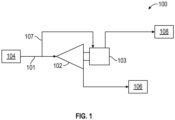
- an aircraft may include one or more cabin air compressors (CACs) 100 which compress an airflow 101, via a compressor 102 driven by a motor 103, with the air entering from an outside source 104, such as bleed air from an engine, or from a ram air system.
- the compressed air is delivered to an environmental control system (ECS) 106, which includes one or more heat exchangers that bring the compressed air to a desired temperature, and then the compressed air is delivered to the aircraft cabin. After passing through the cabin, the air is typically exhausted to the outside or recirculated as the case may be.
- the motor 103 is typically an air-cooled electric motor, which may be cooled by air bleed from the compressor 103 via a bleed duct 107. The spent air may then be dumped overboard 108.
- the CAC includes a rotor 110 and an impeller 120.
- a motor 103 is connected to the rotor 110 to cause the rotor 110 to rotate and move the impeller 120.
- a case 140 of the CAC 100 is shown, extending from forward to aft ends 144, 146.
- the case 140 includes a rotor section 150 that surrounds the rotor 110. It is to be appreciated that the rotor section 150, with the impeller 120 and rotor 110 therein, corresponds to the compressor 102 of FIG. 1 .
- a motor section 160 surrounds the motor 103 and is adjacent to the rotor section 150.
- a CAC inlet 180 is adjacent to the rotor section 150 such that the CAC inlet 180, e.g., which may receive RAM air or air from an engine ( FIG. 1 ), is forward of the rotor section 150 and the motor section is aft of the rotor section 150.
- the CAC inlet 180 supplies an airflow 101 to the rotor section 150.
- a CAC discharge 190 is fluidly coupled to the impeller 120, which may be directed to a heat exchanger of an ECS 106 ( FIG. 1 ) and thereafter to the cabin.
- a bleed duct 107 extends from a bleed duct inlet 210 located in the CAC inlet 180 to a bleed duct outlet 230 located at the motor section 160.
- the bleed duct 107 directs a portion 240 of the airflow 101 (e.g., bleed portion of the airflow), to the motor 103 for cooling the motor 103 during normal operation.
- a portion of the motor cooling airflow flows over the motor stator end turns, and through stator cooling channels located on an outer diameter of the motor stator (not shown).
- Another portion of motor cooling air flow flows through the rotor stator airgap.
- Adequate cooling of the motor provides for increasing a mean-time-before-failure (MTBF) of the CAC motor 103.
- MTBF mean-time-before-failure
- the pathway for the airflow 101 that is diverted from the inlet 180 to the bleed duct 107 may be configured to allow for sufficient airflow to reach the motor 103.
- the pathway may be configured to prevent foreign object debris (FOD), which may enter the inlet 180, from reaching the motor 103.
- FOD foreign object debris
- FIG. 3 a more detailed version of the inlet 180 of the CAC 100 ( FIG. 2 ) is shown that enables directing sufficient bleed airflow to the motor 103, to thereby increase the useful life of the CAC 100.
- a bleed inlet 250 is defined in the CAC inlet 180.
- the bleed inlet 250 is fluidly coupled with the bleed duct inlet 210 ( FIG. 2 ).
- the bleed inlet 250 has a bleed inlet aperture 260 that circumferentially extends (in the circumferential direction 100C for the CAC 100) about the CAC inlet 180 to define a bleed inlet forward end 270 and a bleed inlet aft end 280.
- a scoop 300 is provided in the CAC inlet 180 for guiding the bleed portion 240 of the airflow 101 into the bleed inlet 250.
- the scoop 300 defines a scoop aft end 310 that is connected to the bleed inlet aft end 280.
- a scoop body 320 extends toward the case forward end 144 of the case 140 to a scoop forward end 330.
- the scoop 300 is frustoconical and converges toward the case forward end 144 to provide a radial inlet gap 340 (in the radial direction 100R for the CAC 100) between the scoop forward end 330 and the bleed inlet forward end 270.
- the radial inlet gap 340 is sized to be large enough to receive a sufficient amount of bleed airflow for cooling the motor 103.
- the scoop aft end 310 is radially aligned with an inlet surface 350 that extends aft from the case forward end 144 to the bleed inlet forward end 270.
- the scoop body 320 may be disposed at a scoop angle 360 of between 5 and 30 degrees to the inlet airflow 101, e.g., parallel to a center axis 370 of the CAC inlet 180.
- the scoop forward end 330 is forward of the bleed inlet forward end 270 to define an axial inlet overlap 380 (in the axial direction 100A for the CAC 100).
- the axial inlet overlap 380 may be equal to or greater than the radial inlet gap 340.
- a bleed cavity 400 is defined by a bleed cavity surface 410 that extends from the bleed inlet forward end 270 to the bleed inlet aft end 280 of the bleed inlet aperture 260.
- the bleed cavity 400 surrounds the CAC inlet 180.
- the bleed cavity surface 410 defines a bleed conduit aperture 420.
- a bleed conduit 430 extends radially outward from the bleed conduit aperture 420.
- a filter housing 440 is removably connected between the bleed conduit 430 and the bleed duct 107.
- the filter housing 440 has a filter housing inlet flange 450 and a filter housing outlet flange 460.
- the bleed conduit 430 has a bleed conduit outlet flange 470 that is releasably connected to the filter housing inlet flange 450.
- the bleed duct 107 has a bleed duct inlet flange 480 that is releasably connected to the filter housing outlet flange 460.
- the above disclosed embodiment includes aspects related to the configuration of the scoop 300 at the inlet 180 and the utilization of the filter housing 440, connected between the bleed conduit 430 and the bleed duct 107. In one or more embodiments, however, only one of these aspects may be included in the CAC 100.
- the bleed duct 107 defines an air conduit port 500 through which an air conduit 510 extends.
- An outlet 520 of the air conduit 510 is directed toward filter media 530 in the filter housing 440.
- the air conduit 510 is fluidly coupled to a pressurized air source 540.
- a control valve 550 is fluidly coupled between the pressurized air source 540 and the air conduit 510.
- the control valve 550 is normally in a closed state and is configured to transition to an opened state when a pressure-drop across the filter media 530 is greater than a threshold. In the opened state, the control valve 550 is configured to transition to the closed state after a predetermined period of time.
- pressurized air can dislodge the FOD to enable bleed air to reach the motor 103.
- the pressurized air is applied at a greater pressure than the airflow into the CAC 100.
- air pressurized by the CAC 100 e.g., bled off the CAC discharge 190, may be utilized as the source of pressurized air to clear the filter media 530.
- the CAC 100 is taken offline for the period of time required to apply the pressurized air to the filter media 530.
- FIG. 6 a flowchart shows a method of operating the CAC 100.
- the method includes directing airflow into the CAC inlet 180 at the case forward end 144 of the CAC case 140, to the impeller 120, and out of the discharge 190 that is fluidly coupled to the impeller 120.
- the method includes directing the bleed portion 240 of the airflow 101 from the CAC inlet 180, through the bleed duct 107, to the motor 103 via the radial inlet gap 340 in the CAC inlet 180 defined between the scoop forward end 330 of the scoop 300 that converges toward the forward end of the CAC inlet 180 and the bleed inlet forward end 270.
- the method includes directing the bleed portion 240 of the airflow 101 through the filter housing 440 that is removably connected to the bleed conduit 430. As shown in block 540, the method includes directing the bleed portion 240 of the airflow 101 from the filter housing 440 through the bleed duct 107 that is fluidly coupled to the motor section 160 of the CAC case 140.
- the method includes directing pressurized air, through the air conduit outlet 520 of the air conduit 510 that extends through the air conduit port 500 defined in the bleed duct 107, toward filter media 530 in the filter housing 440.
- the method includes transitioning the control valve 550, that is fluidly coupled to the air conduit 510, intermediate of the air conduit outlet 520 and the pressurized air source 540, to an opened state when a pressure drop across the filter media 530 exceeds a threshold.
- the method includes transitioning the control valve 550 to a closed state after a predetermined period of time.
- the above disclosed embodiments provide an elongated scoop in the CAC inlet section.
- the elongated scoop may provide an enhanced motor cooling flow utilizing the CAC compressor inlet flow.
- a removable filter is provided in the bleed duct. The filter may be automatically cleaned if a pressure-drop across the filter increases beyond a threshold.
Landscapes
- Engineering & Computer Science (AREA)
- Mechanical Engineering (AREA)
- General Engineering & Computer Science (AREA)
- Health & Medical Sciences (AREA)
- General Health & Medical Sciences (AREA)
- Pulmonology (AREA)
- Aviation & Aerospace Engineering (AREA)
- Physics & Mathematics (AREA)
- Thermal Sciences (AREA)
- Structures Of Non-Positive Displacement Pumps (AREA)
- Compressor (AREA)
Abstract
Description
- The subject matter disclosed herein relates to a cabin air compressor with a bleed scoop and a removable bleed duct filter.
- A cabin air compressor includes a motor section having a motor that drives the compressor. Cooling of the motor may be required to prolong the useful life of the cabin air compressor.
- Disclosed is an cabin air compressor (CAC), including: a rotor that includes an impeller; a motor connected to the rotor to cause the rotor to rotate and move the impeller; a case that includes: a rotor section that surrounds the rotor; a motor section that surrounds the motor and is adjacent to the rotor section; a CAC inlet that is adjacent to the rotor section and supplies air to the rotor section, such that the CAC inlet is forward of the rotor section and the motor section is aft of the rotor section, the CAC inlet defining a bleed inlet and has a bleed inlet aperture that circumferentially extends about the CAC inlet to define a bleed inlet forward end and a bleed inlet aft end; and a CAC discharge that is fluidly coupled to the impeller; a bleed duct that extends from a bleed duct inlet located at the CAC inlet to a bleed duct outlet located at the motor section and is fluidly connected to the bleed inlet; and a scoop defining a scoop aft end connected to the bleed inlet aft end, and a scoop body extending toward a case forward end of the case to a scoop forward end, wherein the scoop is frustoconical and converges toward the case forward end to provide a radial inlet gap between the scoop forward end and the bleed inlet forward end.
- In addition to one or more of the above disclosed aspects or as an alternate, the scoop aft end is radially aligned with an inlet surface that extends aft from the case forward end to the bleed inlet forward end, and the scoop body is disposed at a scoop angle of between 5 and 30 degrees to a center axis of the CAC inlet.
- In addition to one or more of the above disclosed aspects or as an alternate, the scoop forward end is forward of the bleed inlet forward end to define an axial inlet overlap.
- In addition to one or more of the above disclosed aspects or as an alternate, the axial inlet overlap is equal to or greater than the radial inlet gap.
- In addition to one or more of the above disclosed aspects or as an alternate, the CAC includes a bleed cavity defined by a bleed cavity surface that extends from the bleed inlet forward end to the bleed inlet aft end of the bleed inlet aperture, wherein the bleed cavity surrounds the CAC inlet, wherein the bleed cavity surface defines a bleed conduit aperture, and a bleed conduit extends radially outward from the bleed conduit aperture; and a filter housing removably connected between the bleed conduit and the bleed duct.
- In addition to one or more of the above disclosed aspects or as an alternate, the filter housing has a filter housing inlet flange; and the bleed conduit has a bleed conduit outlet flange that is releasably connected to the filter housing inlet flange.
- In addition to one or more of the above disclosed aspects or as an alternate, the filter housing has a filter housing outlet flange; and the bleed duct has a bleed duct inlet flange that is releasably connected to the filter housing outlet flange.
- In addition to one or more of the above disclosed aspects or as an alternate, the bleed duct defines an air conduit port through which an air conduit extends such that an outlet of the air conduit is directed toward filter media in the filter housing; and the air conduit is fluidly coupled to a pressurized air source.
- In addition to one or more of the above disclosed aspects or as an alternate, the CAC includes a control valve that is fluidly coupled between the pressurized air source and the air conduit, wherein, in operation, the control valve is normally in a closed state and is configured to transition to an opened state when a pressure-drop across the filter media is greater than a threshold.
- In addition to one or more of the above disclosed aspects or as an alternate, in the opened state, the control valve is configured to transition to the closed state after a predetermined period of time.
- Disclosed is another embodiment of a cabin air compressor (CAC), including: a rotor that includes an impeller; a motor connected to the rotor to cause the rotor to rotate and move the impeller; a case that includes: a rotor section that surrounds the rotor; a motor section that surrounds the motor and is adjacent to the rotor section; a CAC inlet that is adjacent to the rotor section and supplies air to the rotor section, such that the CAC inlet is forward of the rotor section and the motor section is aft of the rotor section, the CAC inlet defining a bleed inlet and has a bleed inlet aperture that circumferentially extends about the CAC inlet to define a bleed inlet forward end and a bleed inlet aft end; and a CAC discharge that is fluidly coupled to the impeller; a bleed duct that extends from a bleed duct inlet located at the CAC inlet to a bleed duct outlet located at the motor section and is fluidly connected to the bleed inlet, wherein: a bleed inlet defined in the CAC inlet is fluidly coupled with the bleed duct inlet and has a bleed inlet aperture that circumferentially extends about the CAC inlet to define a bleed inlet forward end and a bleed inlet aft end; and a bleed cavity defined by a bleed cavity surface that extends from the bleed inlet forward end to the bleed inlet aft end of the bleed inlet aperture, wherein the bleed cavity surrounds the CAC inlet, wherein the bleed cavity surface defines a bleed conduit aperture; a bleed conduit that extends radially outward from the bleed conduit aperture; and a filter housing removably connected between the bleed conduit and the bleed duct.
- In addition to one or more of the above disclosed aspects of the another embodiment, or as an alternate, the filter housing has a filter housing inlet flange; and the bleed conduit has a bleed conduit outlet flange that is releasably connected to the filter housing inlet flange.
- In addition to one or more of the above disclosed aspects of the another embodiment, or as an alternate, the filter housing has a filter housing outlet flange; and the bleed duct has a bleed duct inlet flange that is releasably connected to the filter housing outlet flange.
- In addition to one or more of the above disclosed aspects of the another embodiment, or as an alternate, the bleed duct defines an air conduit port through which an air conduit extends such that an outlet of the air conduit is directed toward filter media in the filter housing; and the air conduit is fluidly coupled to a pressurized air source.
- In addition to one or more of the above disclosed aspects of the another embodiment, or as an alternate, the CAC includes a control valve that is fluidly coupled between the pressurized air source and the air conduit, wherein, in operation, the control valve is normally in a closed state and is configured to transition to an opened state when a pressure-drop across the filter media is greater than a threshold.
- In addition to one or more of the above disclosed aspects of the another embodiment, or as an alternate, in the opened state, the control valve is configured to transition to the closed state after a predetermined period of time.
- Disclosed is a method of operating a cabin air compressor (CAC), including: directing airflow into a CAC inlet at a forward end of a case of the CAC, to an impeller that is caused to rotate by a rotor and is surrounded by a rotor section, and out of a discharge that is fluidly coupled to the impeller; and directing a bleed portion of the airflow from the CAC inlet, through a bleed duct, to a motor that is surrounded by a motor section via a radial inlet gap in the CAC inlet defined between: a scoop forward end of a scoop that is connected to a bleed inlet aft end of a bleed inlet that is defined in the CAC inlet, wherein the scoop is frustoconical and converges toward the forward end of the case; and a bleed inlet forward end of the bleed inlet, wherein the bleed inlet circumferentially extends about the CAC inlet to define the bleed inlet forward end and the bleed inlet aft end.
- In addition to one or more of the above disclosed aspects of the method, or as an alternate, the method includes directing the bleed portion of the airflow through a filter housing that is removably connected to a bleed conduit of the CAC inlet, wherein the bleed conduit extends from a bleed conduit aperture defined by a bleed cavity surface, and wherein the bleed cavity surface extends from the bleed inlet forward end to the bleed inlet aft end and surrounds the CAC inlet; and directing the bleed portion from the filter housing through the bleed duct.
- In addition to one or more of the above disclosed aspects of the method, or as an alternate, the method includes directing pressurized air, through an air conduit outlet of an air conduit extending through an air conduit port defined in the bleed duct, toward filter media in the filter housing.
- In addition to one or more of the above disclosed aspects of the method, or as an alternate, the method includes transitioning a control valve, that is fluidly coupled to the air conduit, intermediate of the air conduit outlet and a pressurized air source, to an opened state when a pressure drop across the filter media exceeds a threshold; and transitioning the control valve to a closed state after a predetermined period of time.
-
- The following descriptions should not be considered limiting in any way. With reference to the accompanying drawings, like elements are numbered alike:
-
FIG. 1 is a schematic of a cabin air compressor (CAC) where embodiments of the present invention can be implemented; -
FIG. 2 shows a cabin air compressor (CAC) according to an embodiment that includes a bleed scoop and a removable bleed duct filter; -
FIG. 3 shows an inlet section of the CAC ofFIG. 2 according to an embodiment, showing additional features of the bleed scoop; -
FIG. 4 shows the inlet of the CAC ofFIG. 2 according to an embodiment, showing additional features of the removable bleed duct filter; -
FIG. 5 shows additional features of the removable bleed duct filter, including an air conduit that extends through a bleed duct of the CAC for clearing debris from the removable bleed duct filter; and -
FIG. 6 is a flowchart showing a method of operating a CAC according to an embodiment. - A detailed description of one or more embodiments of the disclosed apparatus and method are presented herein by way of exemplification and not limitation with reference to the Figures.
- Turning to
FIG. 1 , an aircraft may include one or more cabin air compressors (CACs) 100 which compress anairflow 101, via acompressor 102 driven by amotor 103, with the air entering from anoutside source 104, such as bleed air from an engine, or from a ram air system. The compressed air is delivered to an environmental control system (ECS) 106, which includes one or more heat exchangers that bring the compressed air to a desired temperature, and then the compressed air is delivered to the aircraft cabin. After passing through the cabin, the air is typically exhausted to the outside or recirculated as the case may be. Themotor 103 is typically an air-cooled electric motor, which may be cooled by air bleed from thecompressor 103 via ableed duct 107. The spent air may then be dumped overboard 108. - Turning to
FIG. 2 , the CAC includes arotor 110 and animpeller 120. Amotor 103 is connected to therotor 110 to cause therotor 110 to rotate and move theimpeller 120. Acase 140 of theCAC 100 is shown, extending from forward toaft ends 144, 146. Thecase 140 includes arotor section 150 that surrounds therotor 110. It is to be appreciated that therotor section 150, with theimpeller 120 androtor 110 therein, corresponds to thecompressor 102 ofFIG. 1 . Amotor section 160 surrounds themotor 103 and is adjacent to therotor section 150. ACAC inlet 180 is adjacent to therotor section 150 such that theCAC inlet 180, e.g., which may receive RAM air or air from an engine (FIG. 1 ), is forward of therotor section 150 and the motor section is aft of therotor section 150. The CAC inlet 180 supplies anairflow 101 to therotor section 150. ACAC discharge 190 is fluidly coupled to theimpeller 120, which may be directed to a heat exchanger of an ECS 106 (FIG. 1 ) and thereafter to the cabin. Ableed duct 107 extends from ableed duct inlet 210 located in theCAC inlet 180 to ableed duct outlet 230 located at themotor section 160. - The
bleed duct 107 directs aportion 240 of the airflow 101 (e.g., bleed portion of the airflow), to themotor 103 for cooling themotor 103 during normal operation. A portion of the motor cooling airflow flows over the motor stator end turns, and through stator cooling channels located on an outer diameter of the motor stator (not shown). Another portion of motor cooling air flow flows through the rotor stator airgap. Adequate cooling of the motor provides for increasing a mean-time-before-failure (MTBF) of theCAC motor 103. Thus, the pathway for theairflow 101 that is diverted from theinlet 180 to thebleed duct 107 may be configured to allow for sufficient airflow to reach themotor 103. In addition, the pathway may be configured to prevent foreign object debris (FOD), which may enter theinlet 180, from reaching themotor 103. - Turning to
FIG. 3 a more detailed version of theinlet 180 of the CAC 100 (FIG. 2 ) is shown that enables directing sufficient bleed airflow to themotor 103, to thereby increase the useful life of theCAC 100. Ableed inlet 250 is defined in theCAC inlet 180. Thebleed inlet 250 is fluidly coupled with the bleed duct inlet 210 (FIG. 2 ). Thebleed inlet 250 has ableed inlet aperture 260 that circumferentially extends (in thecircumferential direction 100C for the CAC 100) about theCAC inlet 180 to define a bleed inlet forwardend 270 and a bleedinlet aft end 280. - According to an embodiment, a scoop 300 is provided in the
CAC inlet 180 for guiding thebleed portion 240 of theairflow 101 into thebleed inlet 250. The scoop 300 defines ascoop aft end 310 that is connected to the bleedinlet aft end 280. Ascoop body 320 extends toward the case forward end 144 of thecase 140 to a scoopforward end 330. The scoop 300 is frustoconical and converges toward the case forward end 144 to provide a radial inlet gap 340 (in theradial direction 100R for the CAC 100) between the scoopforward end 330 and the bleed inlet forwardend 270. Theradial inlet gap 340 is sized to be large enough to receive a sufficient amount of bleed airflow for cooling themotor 103. In one embodiment, the scoop aftend 310 is radially aligned with aninlet surface 350 that extends aft from the case forward end 144 to the bleed inletforward end 270. Thescoop body 320 may be disposed at ascoop angle 360 of between 5 and 30 degrees to theinlet airflow 101, e.g., parallel to acenter axis 370 of theCAC inlet 180. In one embodiment, the scoopforward end 330 is forward of the bleed inlet forward end 270 to define an axial inlet overlap 380 (in theaxial direction 100A for the CAC 100). Theaxial inlet overlap 380 may be equal to or greater than theradial inlet gap 340. - Turning to
FIG. 4 , ableed cavity 400 is defined by ableed cavity surface 410 that extends from the bleed inlet forward end 270 to the bleed inlet aftend 280 of thebleed inlet aperture 260. Thebleed cavity 400 surrounds theCAC inlet 180. Thebleed cavity surface 410 defines ableed conduit aperture 420. A bleed conduit 430 extends radially outward from thebleed conduit aperture 420. - According to an embodiment, a
filter housing 440 is removably connected between the bleed conduit 430 and thebleed duct 107. Thefilter housing 440 has a filterhousing inlet flange 450 and a filterhousing outlet flange 460. The bleed conduit 430 has a bleedconduit outlet flange 470 that is releasably connected to the filterhousing inlet flange 450. Thebleed duct 107 has a bleedduct inlet flange 480 that is releasably connected to the filterhousing outlet flange 460. - The above disclosed embodiment includes aspects related to the configuration of the scoop 300 at the
inlet 180 and the utilization of thefilter housing 440, connected between the bleed conduit 430 and thebleed duct 107. In one or more embodiments, however, only one of these aspects may be included in theCAC 100. - Turning to
FIG. 5 , thebleed duct 107 defines anair conduit port 500 through which anair conduit 510 extends. Anoutlet 520 of theair conduit 510 is directed towardfilter media 530 in thefilter housing 440. Theair conduit 510 is fluidly coupled to apressurized air source 540. According to an embodiment, acontrol valve 550 is fluidly coupled between thepressurized air source 540 and theair conduit 510. In operation, thecontrol valve 550 is normally in a closed state and is configured to transition to an opened state when a pressure-drop across thefilter media 530 is greater than a threshold. In the opened state, thecontrol valve 550 is configured to transition to the closed state after a predetermined period of time. Thus, should FOD block, completely or partially, thefilter media 530, pressurized air can dislodge the FOD to enable bleed air to reach themotor 103. In one embodiment, the pressurized air is applied at a greater pressure than the airflow into theCAC 100. Thus the CAC does not need to be deactivated when applying pressurized air. In on embodiment, air pressurized by theCAC 100, e.g., bled off theCAC discharge 190, may be utilized as the source of pressurized air to clear thefilter media 530. In one embodiment, theCAC 100 is taken offline for the period of time required to apply the pressurized air to thefilter media 530. - Turning to
FIG. 6 a flowchart shows a method of operating theCAC 100. As shown inblock 510, the method includes directing airflow into theCAC inlet 180 at the case forward end 144 of theCAC case 140, to theimpeller 120, and out of thedischarge 190 that is fluidly coupled to theimpeller 120. As shown inblock 520, the method includes directing thebleed portion 240 of theairflow 101 from theCAC inlet 180, through thebleed duct 107, to themotor 103 via theradial inlet gap 340 in theCAC inlet 180 defined between the scoop forward end 330 of the scoop 300 that converges toward the forward end of theCAC inlet 180 and the bleed inletforward end 270. - As shown in
block 530, the method includes directing thebleed portion 240 of theairflow 101 through thefilter housing 440 that is removably connected to the bleed conduit 430. As shown inblock 540, the method includes directing thebleed portion 240 of theairflow 101 from thefilter housing 440 through thebleed duct 107 that is fluidly coupled to themotor section 160 of theCAC case 140. - As shown in
block 550, the method includes directing pressurized air, through theair conduit outlet 520 of theair conduit 510 that extends through theair conduit port 500 defined in thebleed duct 107, towardfilter media 530 in thefilter housing 440. As shown inblock 560, the method includes transitioning thecontrol valve 550, that is fluidly coupled to theair conduit 510, intermediate of theair conduit outlet 520 and thepressurized air source 540, to an opened state when a pressure drop across thefilter media 530 exceeds a threshold. As shown inblock 570, the method includes transitioning thecontrol valve 550 to a closed state after a predetermined period of time. - The above disclosed embodiments provide an elongated scoop in the CAC inlet section. To increase motor reliability, the elongated scoop may provide an enhanced motor cooling flow utilizing the CAC compressor inlet flow. To prevent ingestion of FOD, which could otherwise reduce a motor cooling flow, a removable filter is provided in the bleed duct. The filter may be automatically cleaned if a pressure-drop across the filter increases beyond a threshold.
- The terminology used herein is for the purpose of describing particular embodiments only and is not intended to be limiting of the present disclosure. As used herein, the singular forms "a", "an" and "the" are intended to include the plural forms as well, unless the context clearly indicates otherwise. It will be further understood that the terms "comprises" and/or "comprising," when used in this specification, specify the presence of stated features, integers, steps, operations, elements, and/or components, but do not preclude the presence or addition of one or more other features, integers, steps, operations, element components, and/or groups thereof.
- While the present disclosure has been described with reference to an exemplary embodiment or embodiments, it will be understood by those skilled in the art that various changes may be made and equivalents may be substituted for elements thereof without departing from the scope of the present disclosure. In addition, many modifications may be made to adapt a particular situation or material to the teachings of the present disclosure without departing from the essential scope thereof. Therefore, it is intended that the present disclosure not be limited to the particular embodiment disclosed as the best mode contemplated for carrying out this present disclosure, but that the present disclosure will include all embodiments falling within the scope of the claims.
Claims (15)
- A cabin air compressor "CAC", comprising:a rotor (110) that includes an impeller;a motor (103) connected to the rotor (110) to cause the rotor (110) to rotate and move the impeller;a case that includes:a rotor section (150) that surrounds the rotor (110);a motor (103) section that surrounds the motor (103) and is adjacent to the rotor section (150);a CAC inlet that is adjacent to the rotor section (150) and supplies air to the rotor section (150), such that the CAC inlet is forward of the rotor section (150) and the motor section (160) is aft of the rotor section (150), the CAC inlet defining a bleed inlet and has a bleed inlet aperture that circumferentially extends about the CAC inlet to define a bleed inlet forward end and a bleed inlet aft end; anda CAC discharge that is fluidly coupled to the impeller;a bleed duct (107) that extends from a bleed duct inlet located at the CAC inlet to a bleed duct outlet located at the motor section (160) and is fluidly connected to the bleed inlet; anda scoop (300) defining a scoop aft end connected to the bleed inlet aft end, and a scoop body extending toward a case forward end of the case to a scoop forward end,wherein the scoop (300) is frustoconical and converges toward the case forward end to provide a radial inlet gap between the scoop forward end and the bleed inlet forward end.
- The CAC of claim 1, wherein:
the scoop aft end is radially aligned with an inlet surface that extends aft from the case forward end to the bleed inlet forward end, and the scoop body is disposed at a scoop angle of between 5 and 30 degrees to a center axis of the CAC inlet. - The CAC of claim 1 or 2, wherein:
the scoop forward end is forward of the bleed inlet forward end to define an axial inlet overlap, and optionally wherein:
the axial inlet overlap is equal to or greater than the radial inlet gap. - The CAC of any preceding claim, further comprising:a bleed cavity defined by a bleed cavity surface that extends from the bleed inlet forward end to the bleed inlet aft end of the bleed inlet aperture, wherein the bleed cavity surrounds the CAC inlet,wherein the bleed cavity surface defines a bleed conduit aperture, and a bleed conduit extends radially outward from the bleed conduit aperture; anda filter housing removably connected between the bleed conduit and the bleed duct (107).
- The CAC of claim 4, wherein:the filter housing has a filter housing inlet flange; andthe bleed conduit has a bleed conduit outlet flange that is releasably connected to the filter housing inlet flange.
- The CAC of claim 4 or 5, wherein:the filter housing has a filter housing outlet flange; andthe bleed duct (107) has a bleed duct inlet flange that is releasably connected to the filter housing outlet flange.
- The CAC of claim 6, wherein:the bleed duct (107) defines an air conduit port through which an air conduit extends such that an outlet of the air conduit is directed toward filter media in the filter housing; andthe air conduit is fluidly coupled to a pressurized air source, and optionally . further comprising:a control valve that is fluidly coupled between the pressurized air source and the air conduit,wherein, in operation, the control valve is normally in a closed state and is configured to transition to an opened state when a pressure-drop across the filter media is greater than a threshold, and optionally wherein:
in the opened state, the control valve is configured to transition to the closed state after a predetermined period of time. - A cabin air compressor (CAC), comprising:a rotor (110) that includes an impeller;a motor (103) connected to the rotor (110) to cause the rotor (110) to rotate and move the impeller;a case that includes:a rotor section (150) that surrounds the rotor (110);a motor section (160) that surrounds the motor (103) and is adjacent to the rotor section (150);a CAC inlet that is adjacent to the rotor section (150) and supplies air to the rotor section (150), such that the CAC inlet is forward of the rotor section (150) and the motor section (160) is aft of the rotor section (150), the CAC inlet defining a bleed inlet and has a bleed inlet aperture that circumferentially extends about the CAC inlet to define a bleed inlet forward end and a bleed inlet aft end; anda CAC discharge that is fluidly coupled to the impeller;a bleed duct (107) that extends from a bleed duct inlet located at the CAC inlet to a bleed duct outlet located at the motor section (160) and is fluidly connected to the bleed inlet,wherein:a bleed inlet defined in the CAC inlet is fluidly coupled with the bleed duct inlet and has a bleed inlet aperture that circumferentially extends about the CAC inlet to define a bleed inlet forward end and a bleed inlet aft end; anda bleed cavity defined by a bleed cavity surface that extends from the bleed inlet forward end to the bleed inlet aft end of the bleed inlet aperture, wherein the bleed cavity surrounds the CAC inlet,wherein the bleed cavity surface defines a bleed conduit aperture;a bleed conduit that extends radially outward from the bleed conduit aperture; anda filter housing removably connected between the bleed conduit and the bleed duct (107).
- The CAC of claim 8, wherein:the filter housing has a filter housing inlet flange; andthe bleed conduit has a bleed conduit outlet flange that is releasably connected to the filter housing inlet flange.
- The CAC of claim 9, wherein:the filter housing has a filter housing outlet flange; andthe bleed duct (107) has a bleed duct inlet flange that is releasably connected to the filter housing outlet flange.
- The CAC of claim 10, wherein:the bleed duct (107) defines an air conduit port through which an air conduit extends such that an outlet of the air conduit is directed toward filter media in the filter housing; andthe air conduit is fluidly coupled to a pressurized air source.
- The CAC of claim 11, further comprising:a control valve that is fluidly coupled between the pressurized air source and the air conduit,wherein, in operation, the control valve is normally in a closed state and is configured to transition to an opened state when a pressure-drop across the filter media is greater than a threshold, and optionally wherein:
in the opened state, the control valve is configured to transition to the closed state after a predetermined period of time. - A method of operating a cabin air compressor (CAC), comprising:directing airflow into a CAC inlet at a forward end of a case of the CAC, to an impeller that is caused to rotate by a rotor (110) and is surrounded by a rotor section (150), and out of a discharge that is fluidly coupled to the impeller; anddirecting a bleed portion of the airflow from the CAC inlet, through a bleed duct (107), to a motor (103) that is surrounded by a motor section (160) via a radial inlet gap in the CAC inlet defined between:a scoop forward end of a scoop (300) that is connected to a bleed inlet aft end of a bleed inlet that is defined in the CAC inlet, wherein the scoop (300) is frustoconical and converges toward the forward end of the case; anda bleed inlet forward end of the bleed inlet,wherein the bleed inlet circumferentially extends about the CAC inlet to define the bleed inlet forward end and the bleed inlet aft end.
- The method of claim 13, comprising:directing the bleed portion of the airflow through a filter housing that is removably connected to a bleed conduit of the CAC inlet,wherein the bleed conduit extends from a bleed conduit aperture defined by a bleed cavity surface, and wherein the bleed cavity surface extends from the bleed inlet forward end to the bleed inlet aft end and surrounds the CAC inlet; anddirecting the bleed portion from the filter housing through the bleed duct (107).
- The method of claim 13 or 14, comprising:
directing pressurized air, through an air conduit outlet of an air conduit extending through an air conduit port defined in the bleed duct (107), toward filter media in the filter housing, and optionally comprising:transitioning a control valve, that is fluidly coupled to the air conduit, intermediate of the air conduit outlet and a pressurized air source, to an opened state when a pressure drop across the filter media exceeds a threshold; andtransitioning the control valve to a closed state after a predetermined period of time.
Applications Claiming Priority (1)
| Application Number | Priority Date | Filing Date | Title |
|---|---|---|---|
| US17/469,330 US11661954B2 (en) | 2021-09-08 | 2021-09-08 | Cabin air compressor with bleed scoop and removable bleed duct filter |
Publications (3)
| Publication Number | Publication Date |
|---|---|
| EP4148278A2 true EP4148278A2 (en) | 2023-03-15 |
| EP4148278A3 EP4148278A3 (en) | 2023-05-24 |
| EP4148278B1 EP4148278B1 (en) | 2025-12-31 |
Family
ID=83004552
Family Applications (1)
| Application Number | Title | Priority Date | Filing Date |
|---|---|---|---|
| EP22191045.8A Active EP4148278B1 (en) | 2021-09-08 | 2022-08-18 | Cabin air compressor with vent valve and removable vent channel filter |
Country Status (2)
| Country | Link |
|---|---|
| US (1) | US11661954B2 (en) |
| EP (1) | EP4148278B1 (en) |
Families Citing this family (2)
| Publication number | Priority date | Publication date | Assignee | Title |
|---|---|---|---|---|
| EP4435264A1 (en) * | 2023-03-21 | 2024-09-25 | Rolls-Royce plc | Air pressurisation system |
| US12494698B2 (en) * | 2023-07-11 | 2025-12-09 | Hamilton Sundstrand Corporation | Systems and methods for cooling motors |
Family Cites Families (13)
| Publication number | Priority date | Publication date | Assignee | Title |
|---|---|---|---|---|
| US5311749A (en) | 1992-04-03 | 1994-05-17 | United Technologies Corporation | Turbine bypass working fluid admission |
| JP3425308B2 (en) * | 1996-09-17 | 2003-07-14 | 株式会社 日立インダストリイズ | Multistage compressor |
| US7861968B2 (en) | 2006-10-26 | 2011-01-04 | The Boeing Company | Air inlet and method for a highspeed mobile platform |
| US7624944B2 (en) | 2006-10-26 | 2009-12-01 | The Boeing Company | Tandem air inlet apparatus and method for an airborne mobile platform |
| US8863548B2 (en) | 2010-07-16 | 2014-10-21 | Hamilton Sundstrand Corporation | Cabin air compressor motor cooling |
| US9254920B2 (en) | 2012-05-30 | 2016-02-09 | General Electric Company | Aircraft energy management system including engine fan discharge air boosted environmental control system |
| US9181959B2 (en) | 2012-08-07 | 2015-11-10 | Hamilton Sundstrand Corporation | Motor housing |
| US9381787B2 (en) | 2012-10-26 | 2016-07-05 | Hamilton Sundstrand Corporation | Generally wye shaped elbow for cabin air flow system |
| US9685835B2 (en) * | 2013-10-11 | 2017-06-20 | Hamilton Sundstrand Corporation | Motor housing having conical shaped ends with various dimensional ratios and slopes for a stator in an avionics cabin air compressor |
| CN203722411U (en) | 2013-12-23 | 2014-07-16 | 上海大郡动力控制技术有限公司 | Internal and external double air-cooled motor for new-energy automobile |
| US10472072B2 (en) * | 2015-11-25 | 2019-11-12 | Hamilton Sundstrand Corporation | Supply tube for sensor |
| US10807722B2 (en) | 2017-07-11 | 2020-10-20 | Hamilton Sunstrand Corporation | Cabin air compressor motor cooling flow enhancement cowl |
| CN108590840B (en) | 2018-04-19 | 2020-05-08 | 浙江吉利控股集团有限公司 | A turbocharger cooling system for an automobile engine |
-
2021
- 2021-09-08 US US17/469,330 patent/US11661954B2/en active Active
-
2022
- 2022-08-18 EP EP22191045.8A patent/EP4148278B1/en active Active
Also Published As
| Publication number | Publication date |
|---|---|
| EP4148278A3 (en) | 2023-05-24 |
| US20230075905A1 (en) | 2023-03-09 |
| US11661954B2 (en) | 2023-05-30 |
| EP4148278B1 (en) | 2025-12-31 |
Similar Documents
| Publication | Publication Date | Title |
|---|---|---|
| EP3705685B1 (en) | System and method of reducing post-shutdown engine temperatures | |
| EP2407380B1 (en) | Cabin air compressor motor cooling | |
| EP2955334B1 (en) | Method and apparatus for controlling a compressor of a gas turbine engine | |
| EP4148278B1 (en) | Cabin air compressor with vent valve and removable vent channel filter | |
| EP3945030B1 (en) | Aircraft environmental control system | |
| EP3945024B1 (en) | Aircraft environmental control system | |
| EP3421364B1 (en) | Three wheel and simple cycle aircraft environmental control system | |
| EP3100953B1 (en) | Ecs with multiple operation modes and method | |
| EP3248881B1 (en) | Multiple nozzle configurations for a turbine of an environmental control system | |
| US11897618B2 (en) | Cabin air compressor with liquid cooled passage formed in the case | |
| EP4019785B1 (en) | Cabin air compressor with liquid cooled jacket | |
| EP3945028B1 (en) | Aircraft environmental control system | |
| EP4159988B1 (en) | Ambient air environmental control system | |
| EP3666656B1 (en) | Alternate fresh air compressor intake for environmental control system | |
| US20180355801A1 (en) | System and method for cleaning cooling passages of a combustion chamber | |
| EP4382427B1 (en) | Environmental control system including mixed-flow turbine | |
| EP3521169B1 (en) | Three wheel and simple cycle aircraft environmental control system |
Legal Events
| Date | Code | Title | Description |
|---|---|---|---|
| PUAI | Public reference made under article 153(3) epc to a published international application that has entered the european phase |
Free format text: ORIGINAL CODE: 0009012 |
|
| STAA | Information on the status of an ep patent application or granted ep patent |
Free format text: STATUS: THE APPLICATION HAS BEEN PUBLISHED |
|
| AK | Designated contracting states |
Kind code of ref document: A2 Designated state(s): AL AT BE BG CH CY CZ DE DK EE ES FI FR GB GR HR HU IE IS IT LI LT LU LV MC MK MT NL NO PL PT RO RS SE SI SK SM TR |
|
| PUAL | Search report despatched |
Free format text: ORIGINAL CODE: 0009013 |
|
| AK | Designated contracting states |
Kind code of ref document: A3 Designated state(s): AL AT BE BG CH CY CZ DE DK EE ES FI FR GB GR HR HU IE IS IT LI LT LU LV MC MK MT NL NO PL PT RO RS SE SI SK SM TR |
|
| RIC1 | Information provided on ipc code assigned before grant |
Ipc: F04D 29/58 20060101ALI20230419BHEP Ipc: F04D 29/42 20060101ALI20230419BHEP Ipc: F04D 25/06 20060101ALI20230419BHEP Ipc: F04D 17/10 20060101AFI20230419BHEP |
|
| STAA | Information on the status of an ep patent application or granted ep patent |
Free format text: STATUS: REQUEST FOR EXAMINATION WAS MADE |
|
| 17P | Request for examination filed |
Effective date: 20231122 |
|
| RBV | Designated contracting states (corrected) |
Designated state(s): AL AT BE BG CH CY CZ DE DK EE ES FI FR GB GR HR HU IE IS IT LI LT LU LV MC MK MT NL NO PL PT RO RS SE SI SK SM TR |
|
| GRAP | Despatch of communication of intention to grant a patent |
Free format text: ORIGINAL CODE: EPIDOSNIGR1 |
|
| STAA | Information on the status of an ep patent application or granted ep patent |
Free format text: STATUS: GRANT OF PATENT IS INTENDED |
|
| INTG | Intention to grant announced |
Effective date: 20250724 |
|
| GRAS | Grant fee paid |
Free format text: ORIGINAL CODE: EPIDOSNIGR3 |
|
| GRAA | (expected) grant |
Free format text: ORIGINAL CODE: 0009210 |
|
| STAA | Information on the status of an ep patent application or granted ep patent |
Free format text: STATUS: THE PATENT HAS BEEN GRANTED |
|
| AK | Designated contracting states |
Kind code of ref document: B1 Designated state(s): AL AT BE BG CH CY CZ DE DK EE ES FI FR GB GR HR HU IE IS IT LI LT LU LV MC MK MT NL NO PL PT RO RS SE SI SK SM TR |
|
| REG | Reference to a national code |
Ref country code: CH Ref legal event code: F10 Free format text: ST27 STATUS EVENT CODE: U-0-0-F10-F00 (AS PROVIDED BY THE NATIONAL OFFICE) Effective date: 20251231 Ref country code: GB Ref legal event code: FG4D |
|
| REG | Reference to a national code |
Ref country code: DE Ref legal event code: R096 Ref document number: 602022027762 Country of ref document: DE |
|
| REG | Reference to a national code |
Ref country code: IE Ref legal event code: FG4D |
|
| REG | Reference to a national code |
Ref country code: LT Ref legal event code: MG9D |
|
| PG25 | Lapsed in a contracting state [announced via postgrant information from national office to epo] |
Ref country code: NO Free format text: LAPSE BECAUSE OF FAILURE TO SUBMIT A TRANSLATION OF THE DESCRIPTION OR TO PAY THE FEE WITHIN THE PRESCRIBED TIME-LIMIT Effective date: 20260331 |
|
| PG25 | Lapsed in a contracting state [announced via postgrant information from national office to epo] |
Ref country code: FI Free format text: LAPSE BECAUSE OF FAILURE TO SUBMIT A TRANSLATION OF THE DESCRIPTION OR TO PAY THE FEE WITHIN THE PRESCRIBED TIME-LIMIT Effective date: 20251231 Ref country code: HR Free format text: LAPSE BECAUSE OF FAILURE TO SUBMIT A TRANSLATION OF THE DESCRIPTION OR TO PAY THE FEE WITHIN THE PRESCRIBED TIME-LIMIT Effective date: 20251231 |
|
| PG25 | Lapsed in a contracting state [announced via postgrant information from national office to epo] |
Ref country code: RS Free format text: LAPSE BECAUSE OF FAILURE TO SUBMIT A TRANSLATION OF THE DESCRIPTION OR TO PAY THE FEE WITHIN THE PRESCRIBED TIME-LIMIT Effective date: 20260331 |
|
| PG25 | Lapsed in a contracting state [announced via postgrant information from national office to epo] |
Ref country code: LV Free format text: LAPSE BECAUSE OF FAILURE TO SUBMIT A TRANSLATION OF THE DESCRIPTION OR TO PAY THE FEE WITHIN THE PRESCRIBED TIME-LIMIT Effective date: 20251231 |
|
| PG25 | Lapsed in a contracting state [announced via postgrant information from national office to epo] |
Ref country code: BG Free format text: LAPSE BECAUSE OF FAILURE TO SUBMIT A TRANSLATION OF THE DESCRIPTION OR TO PAY THE FEE WITHIN THE PRESCRIBED TIME-LIMIT Effective date: 20251231 |
|
| REG | Reference to a national code |
Ref country code: NL Ref legal event code: MP Effective date: 20251231 |