EP4148154A1 - Wire rod of cu-zn-si alloy obtained by up-drawing continuous casting - Google Patents
Wire rod of cu-zn-si alloy obtained by up-drawing continuous casting Download PDFInfo
- Publication number
- EP4148154A1 EP4148154A1 EP21800018.0A EP21800018A EP4148154A1 EP 4148154 A1 EP4148154 A1 EP 4148154A1 EP 21800018 A EP21800018 A EP 21800018A EP 4148154 A1 EP4148154 A1 EP 4148154A1
- Authority
- EP
- European Patent Office
- Prior art keywords
- mass
- wire rod
- less
- range
- continuous casting
- Prior art date
- Legal status (The legal status is an assumption and is not a legal conclusion. Google has not performed a legal analysis and makes no representation as to the accuracy of the status listed.)
- Withdrawn
Links
- 238000009749 continuous casting Methods 0.000 title claims abstract description 53
- 229910000676 Si alloy Inorganic materials 0.000 title description 2
- 150000001875 compounds Chemical class 0.000 claims abstract description 48
- 229910045601 alloy Inorganic materials 0.000 claims abstract description 41
- 239000000956 alloy Substances 0.000 claims abstract description 41
- 239000012535 impurity Substances 0.000 claims abstract description 4
- 229910052802 copper Inorganic materials 0.000 claims description 15
- 229910052710 silicon Inorganic materials 0.000 claims description 5
- 229910052725 zinc Inorganic materials 0.000 claims description 5
- 238000005266 casting Methods 0.000 description 50
- 239000010949 copper Substances 0.000 description 46
- 239000013078 crystal Substances 0.000 description 34
- 210000001787 dendrite Anatomy 0.000 description 27
- 239000012071 phase Substances 0.000 description 22
- 230000000052 comparative effect Effects 0.000 description 20
- 238000011156 evaluation Methods 0.000 description 19
- 230000007547 defect Effects 0.000 description 18
- 230000010355 oscillation Effects 0.000 description 17
- RYGMFSIKBFXOCR-UHFFFAOYSA-N Copper Chemical compound [Cu] RYGMFSIKBFXOCR-UHFFFAOYSA-N 0.000 description 12
- 238000005259 measurement Methods 0.000 description 11
- 239000000523 sample Substances 0.000 description 11
- XLYOFNOQVPJJNP-UHFFFAOYSA-N water Substances O XLYOFNOQVPJJNP-UHFFFAOYSA-N 0.000 description 11
- 238000004519 manufacturing process Methods 0.000 description 10
- 239000002994 raw material Substances 0.000 description 10
- 239000002184 metal Substances 0.000 description 9
- 229910052751 metal Inorganic materials 0.000 description 9
- 230000015572 biosynthetic process Effects 0.000 description 8
- 238000002425 crystallisation Methods 0.000 description 7
- 230000008025 crystallization Effects 0.000 description 7
- 238000010586 diagram Methods 0.000 description 7
- 238000010438 heat treatment Methods 0.000 description 7
- 239000002054 inoculum Substances 0.000 description 7
- 238000002844 melting Methods 0.000 description 7
- 230000008018 melting Effects 0.000 description 7
- 238000010622 cold drawing Methods 0.000 description 6
- 238000001816 cooling Methods 0.000 description 6
- 239000000463 material Substances 0.000 description 6
- 239000000203 mixture Substances 0.000 description 6
- 230000007423 decrease Effects 0.000 description 5
- 230000000694 effects Effects 0.000 description 5
- 239000002245 particle Substances 0.000 description 5
- 229910000881 Cu alloy Inorganic materials 0.000 description 4
- 230000001133 acceleration Effects 0.000 description 4
- 238000000034 method Methods 0.000 description 4
- 238000005498 polishing Methods 0.000 description 4
- 238000007711 solidification Methods 0.000 description 4
- 230000008023 solidification Effects 0.000 description 4
- 239000000126 substance Substances 0.000 description 4
- 238000005406 washing Methods 0.000 description 4
- OKTJSMMVPCPJKN-UHFFFAOYSA-N Carbon Chemical compound [C] OKTJSMMVPCPJKN-UHFFFAOYSA-N 0.000 description 3
- 230000006866 deterioration Effects 0.000 description 3
- 229910002804 graphite Inorganic materials 0.000 description 3
- 239000010439 graphite Substances 0.000 description 3
- 238000005096 rolling process Methods 0.000 description 3
- 239000007790 solid phase Substances 0.000 description 3
- 239000000243 solution Substances 0.000 description 3
- VHUUQVKOLVNVRT-UHFFFAOYSA-N Ammonium hydroxide Chemical compound [NH4+].[OH-] VHUUQVKOLVNVRT-UHFFFAOYSA-N 0.000 description 2
- 229910001369 Brass Inorganic materials 0.000 description 2
- 229910017518 Cu Zn Inorganic materials 0.000 description 2
- 229910017752 Cu-Zn Inorganic materials 0.000 description 2
- 229910017943 Cu—Zn Inorganic materials 0.000 description 2
- MHAJPDPJQMAIIY-UHFFFAOYSA-N Hydrogen peroxide Chemical compound OO MHAJPDPJQMAIIY-UHFFFAOYSA-N 0.000 description 2
- 235000011114 ammonium hydroxide Nutrition 0.000 description 2
- 239000010951 brass Substances 0.000 description 2
- TVZPLCNGKSPOJA-UHFFFAOYSA-N copper zinc Chemical compound [Cu].[Zn] TVZPLCNGKSPOJA-UHFFFAOYSA-N 0.000 description 2
- 238000005520 cutting process Methods 0.000 description 2
- 229910001651 emery Inorganic materials 0.000 description 2
- 238000005530 etching Methods 0.000 description 2
- 238000001192 hot extrusion Methods 0.000 description 2
- 238000009434 installation Methods 0.000 description 2
- 239000011259 mixed solution Substances 0.000 description 2
- 239000000725 suspension Substances 0.000 description 2
- 238000009864 tensile test Methods 0.000 description 2
- 238000012360 testing method Methods 0.000 description 2
- 229910052582 BN Inorganic materials 0.000 description 1
- PZNSFCLAULLKQX-UHFFFAOYSA-N Boron nitride Chemical compound N#B PZNSFCLAULLKQX-UHFFFAOYSA-N 0.000 description 1
- 229910017758 Cu-Si Inorganic materials 0.000 description 1
- 229910017931 Cu—Si Inorganic materials 0.000 description 1
- 229910007735 Zr—Si Inorganic materials 0.000 description 1
- 239000000654 additive Substances 0.000 description 1
- 230000000996 additive effect Effects 0.000 description 1
- 230000002411 adverse Effects 0.000 description 1
- QVGXLLKOCUKJST-UHFFFAOYSA-N atomic oxygen Chemical compound [O] QVGXLLKOCUKJST-UHFFFAOYSA-N 0.000 description 1
- 238000004581 coalescence Methods 0.000 description 1
- 238000012790 confirmation Methods 0.000 description 1
- 239000000498 cooling water Substances 0.000 description 1
- 150000001879 copper Chemical class 0.000 description 1
- 238000001514 detection method Methods 0.000 description 1
- 238000007599 discharging Methods 0.000 description 1
- 239000006185 dispersion Substances 0.000 description 1
- 239000003651 drinking water Substances 0.000 description 1
- 235000020188 drinking water Nutrition 0.000 description 1
- 230000007613 environmental effect Effects 0.000 description 1
- 238000002474 experimental method Methods 0.000 description 1
- 238000001125 extrusion Methods 0.000 description 1
- 230000005484 gravity Effects 0.000 description 1
- 239000012774 insulation material Substances 0.000 description 1
- 239000007791 liquid phase Substances 0.000 description 1
- 239000000155 melt Substances 0.000 description 1
- 230000003287 optical effect Effects 0.000 description 1
- 230000003647 oxidation Effects 0.000 description 1
- 238000007254 oxidation reaction Methods 0.000 description 1
- 229910052760 oxygen Inorganic materials 0.000 description 1
- 239000001301 oxygen Substances 0.000 description 1
- 230000000149 penetrating effect Effects 0.000 description 1
- 230000002093 peripheral effect Effects 0.000 description 1
- 238000012545 processing Methods 0.000 description 1
- 238000005204 segregation Methods 0.000 description 1
- 239000008399 tap water Substances 0.000 description 1
- 235000020679 tap water Nutrition 0.000 description 1
- 230000000007 visual effect Effects 0.000 description 1
Images





Classifications
-
- B—PERFORMING OPERATIONS; TRANSPORTING
- B22—CASTING; POWDER METALLURGY
- B22D—CASTING OF METALS; CASTING OF OTHER SUBSTANCES BY THE SAME PROCESSES OR DEVICES
- B22D11/00—Continuous casting of metals, i.e. casting in indefinite lengths
- B22D11/04—Continuous casting of metals, i.e. casting in indefinite lengths into open-ended moulds
- B22D11/055—Cooling the moulds
-
- C—CHEMISTRY; METALLURGY
- C22—METALLURGY; FERROUS OR NON-FERROUS ALLOYS; TREATMENT OF ALLOYS OR NON-FERROUS METALS
- C22C—ALLOYS
- C22C9/00—Alloys based on copper
- C22C9/04—Alloys based on copper with zinc as the next major constituent
-
- B—PERFORMING OPERATIONS; TRANSPORTING
- B22—CASTING; POWDER METALLURGY
- B22D—CASTING OF METALS; CASTING OF OTHER SUBSTANCES BY THE SAME PROCESSES OR DEVICES
- B22D11/00—Continuous casting of metals, i.e. casting in indefinite lengths
- B22D11/001—Continuous casting of metals, i.e. casting in indefinite lengths of specific alloys
- B22D11/004—Copper alloys
-
- B—PERFORMING OPERATIONS; TRANSPORTING
- B22—CASTING; POWDER METALLURGY
- B22D—CASTING OF METALS; CASTING OF OTHER SUBSTANCES BY THE SAME PROCESSES OR DEVICES
- B22D11/00—Continuous casting of metals, i.e. casting in indefinite lengths
- B22D11/005—Continuous casting of metals, i.e. casting in indefinite lengths of wire
-
- B—PERFORMING OPERATIONS; TRANSPORTING
- B22—CASTING; POWDER METALLURGY
- B22D—CASTING OF METALS; CASTING OF OTHER SUBSTANCES BY THE SAME PROCESSES OR DEVICES
- B22D11/00—Continuous casting of metals, i.e. casting in indefinite lengths
- B22D11/04—Continuous casting of metals, i.e. casting in indefinite lengths into open-ended moulds
- B22D11/041—Continuous casting of metals, i.e. casting in indefinite lengths into open-ended moulds for vertical casting
-
- B—PERFORMING OPERATIONS; TRANSPORTING
- B22—CASTING; POWDER METALLURGY
- B22D—CASTING OF METALS; CASTING OF OTHER SUBSTANCES BY THE SAME PROCESSES OR DEVICES
- B22D11/00—Continuous casting of metals, i.e. casting in indefinite lengths
- B22D11/14—Plants for continuous casting
- B22D11/145—Plants for continuous casting for upward casting
-
- B—PERFORMING OPERATIONS; TRANSPORTING
- B22—CASTING; POWDER METALLURGY
- B22D—CASTING OF METALS; CASTING OF OTHER SUBSTANCES BY THE SAME PROCESSES OR DEVICES
- B22D11/00—Continuous casting of metals, i.e. casting in indefinite lengths
- B22D11/16—Controlling or regulating processes or operations
Definitions
- the present invention relates to a wire rod of a Cu-Zn-Si based alloy obtained by up-drawing continuous casting, the wire rod being drawn upward and being subjected to continuous casting.
- free-cutting brass as a copper alloy having excellent machinability has been widely used as a material of various parts such as a water contact metal fitting (for example, water faucet fittings of water supply pipe, valves, cocks, joints, flanges, faucet fittings, in-house built device, water discharging tools, joint clip, boiler parts, or the like) used continuously or temporarily in contact with water (tap water or the like), a friction engaging member (for example, bearing, gear, cylinder, bearing retainer, impeller, pump parts, bearing or the like) making a relative movement to a facing member (rotating shaft or the like) continuously or temporarily in contact with the facing member or the like, or a structural material thereof.
- a water contact metal fitting for example, water faucet fittings of water supply pipe, valves, cocks, joints, flanges, faucet fittings, in-house built device, water discharging tools, joint clip, boiler parts, or the like
- a friction engaging member for example, bearing, gear, cylinder, bearing retainer, impeller,
- Pb has been added to a Cu-Zn alloy to improve machinability of the above-mentioned free-cutting brass.
- the use of Pb has been restricted from the viewpoint of environmental problems and other issues, and the application thereof is significantly restricted.
- a Cu-Zn-Si based alloy disclosed in Patent Document 1 has been provided as a copper alloy having excellent machinability even though the amount of Pb is significantly reduced. Since this Cu-Zn-Si based alloy does not contain Pb, the Cu-Zn-Si based alloy can be used for various parts such as water faucet fittings of water supply pipe, water supply and drainage fittings, valves, and water meter fittings, with which drinking water is brought into contact.
- rods and wire rods having various cross-sections may be used as processing materials.
- the rods and wire rods are usually manufactured by carrying out hot extrusion or rolling on large ingots to make rods, and these rods are subjected to plastic working such as drawing working.
- plastic working such as drawing working.
- it is necessary to carry out various steps such as a casting step of producing a large ingot, a heating step of heating the ingot, and an extrusion step of extruding the heated ingot or a rolling step, which requires a large amount of manufacturing cost and manufacturing time.
- a continuous casting method of installing a casting mold in a casting furnace in which the metal melt is stored, and continuously casting a cast wire rod is provided as disclosed in Patent Documents 2 to 5.
- a mold having a self-lubricating property such as graphite is usually used.
- an equipment configuration is relatively simple, and installation cost can be reduced.
- the casting furnace on which the casting mold is attached may be changed, which is suitable for small amount and various type production.
- the casting mold is not sufficiently filled with the metal melt, and casting defects such as sink marks may occur.
- the oscillation mark may be deeper.
- coarsened dendrites are likely to be generated, and cold workability may be deteriorated.
- the Cu-Zn-Si based alloy was not stably cast by the up-drawing casting apparatus.
- the present invention has been made against the background of the above circumstances, and an objective is to provide a wire rod of a Cu-Zn-Si based alloy obtained by up-drawing continuous casting, which enables casting defects to less likely occur and enables the occurrence of coarsened dendrites to be prevented, and which is excellent in cold workability.
- a wire rod of a Cu-Zn-Si based alloy obtained by up-drawing continuous casting of the present invention contains Cu, Zn, and Si, an amount of Cu is within a range of 75.0 mass% or more and 76.9 mass% or less, an amount of Si is within a range of 2.6 mass% or more and 3.1 mass% or less, an amount of Zr is within a range of 0.003 mass% or more and 0.20 mass% or less, an amount of P is within a range of 0.02 mass% or more and 0.15 mass% or less, a balance is composed of Zn and inevitable impurities, and a number density of a Zr-P compound containing Zr and P is within a range of 1500 pieces/mm 2 or more and 7000 pieces/mm 2 or less.
- the Zr-P compound containing Zr and P is produced, and a primary crystal ⁇ -phase is crystallized by using this Zr-P compound as an inoculant nucleus; thereby, it is possible to prevent dendrites from being coarsened.
- the number density of the Zr-P compound containing Zr and P is within a range of 1500 pieces/mm 2 or more and 7000 pieces/mm 2 or less, the effect of preventing the dendrites from being coarsened, which is caused by the Zr-P compound, can be sufficiently achieved.
- the mass ratio Zr/P of Zr to P is preferably less than 1.9, and the mass ratio Cu/Si of Cu to Si is preferably more than 25.
- the mass ratio Zr/P of Zr to P is less than 1.9 and the mass ratio Cu/Si of Cu to Si is more than 25, excessive production of the Zr-P compound can be prevented, and primary crystal ⁇ -phases can be prevented from being bonded to each other to be coarsened, thereby preventing the deterioration of mechanical properties. In addition, a decrease in workability caused by the Zr-P compound can be surely prevented.
- the mass ratio Zr/P of Zr to P is preferably more than 4.2, and the mass ratio Cu/Si of Cu to Si is preferably more than 25.
- the mass ratio Zr/P of Zr to P is more than 4.2 and the mass ratio Cu/Si of Cu to Si is more than 25, excessive production of the Zr-P compound can be prevented, and primary crystal ⁇ -phases can be prevented from being bonded to each other to be coarsened, thereby reducing the deterioration of mechanical properties. In addition, a decrease in workability caused by the Zr-P compound can be surely prevented.
- the tensile strength is preferably within a range of 500 N/mm 2 or more and 540 N/mm 2 or less, and the elongation is preferably within a range of 5% or more and 15% or less.
- the up-drawing continuous cast wire rod has sufficient ductility and is particularly excellent in cold workability.
- the wire rod of a Cu-Zn-Si based alloy obtained by up-drawing continuous casting, which enables casting defects to less likely occur and enables the occurrence of coarsened dendrites to be prevented, and which is excellent in cold workability.
- the wire rod of a Cu-Zn-Si based alloy obtained by up-drawing continuous casting of the present embodiment has a circular cross-section orthogonal to the longitudinal direction, and a cross-sectional area of the cross-section is within a range of 15 mm 2 or more and 500 mm 2 or less.
- the wire rod of a Cu-Zn-Si based alloy obtained by up-drawing continuous casting of the present embodiment has a composition in which an amount of Cu is within a range of 75.0 mass% or more and 76.9 mass% or less, an amount of Si is within a range of 2.6 mass% or more and 3.1 mass% or less, an amount of Zr is within a range of 0.003 mass% or more and 0.20 mass% or less, an amount of P is within a range of 0.02 mass% or more and 0.15 mass% or less, and a balance is composed of Zn and inevitable impurities.
- the wire rod of a Cu-Zn-Si based alloy obtained by up-drawing continuous casting of the present embodiment has a number density of a Zr-P compound containing Zr and P within a range of 1500 pieces/mm 2 or more and 7000 pieces/mm 2 or less.
- the mass ratio Zr/P of Zr to P is preferably less than 1.9, or the mass ratio Zr/P of Zr to P is preferably more than 4.2, and the mass ratio Cu/Si of Cu to Si is preferably more than 25.
- the tensile strength is preferably within a range of 500 N/mm 2 or more and 540 N/mm 2 or less, and the elongation is preferably within a range of 5% or more and 15% or less.
- Zr is co-added with P, thereby producing the Zr-P compound containing Zr and P.
- These Zr-P compound particles are used as inoculant nuclei to form a primary crystal ⁇ -phase, resulting in fine dendrite formation and granular crystallization of the ⁇ -phase crystallized during solidification.
- Zr has a strong affinity for oxygen
- Zr oxide and other substances are likely to be generated.
- the viscosity of the metal melt increases, and defects such as oxides are likely to occur during casting.
- blow holes and microporosities are likely to occur.
- the amount of Zr is set within a range of 0.003 mass% or more and 0.20 mass% or less.
- the lower limit of the amount of Zr is preferably 0.004 mass% or more, and still more preferably 0.005 mass% or more.
- the upper limit of the amount of Zr is preferably 0.18 mass% or less, and still more preferably 0.16 mass% or less.
- P is co-added with Zr to produce a Zr-P compound containing Zr and P, and the Zr-P compound particles are used as an inoculant nucleus to form a primary crystal ⁇ -phase.
- fine dendrite formation and granular crystallization can be achieved.
- cracks are likely to occur on a surface or the inside of an ingot during the formation of the ingot, and disconnection is likely to occur during working.
- the amount of P is set within a range of 0.02 mass% or more and 0.15 mass% or less.
- the lower limit of the amount of P is preferably 0.03 mass% or more, and still more preferably 0.08 mass% or more.
- the upper limit of the amount of P is preferably 0.13 mass% or less, and still more preferably 0.10 mass% or less.
- the Zr-P compound particles are used as inoculant nuclei to form the primary crystal ⁇ -phase, resulting in fine dendrite formation and granular crystallization of the crystallized ⁇ -phase.
- a Cu concentration is set to 75.0 mass% or more, and a Si concentration is relatively lowered to obtain a region of the primary crystal ⁇ -phase, and fine dendrite formation and granular crystallization can be achieved.
- the Cu concentration is more than 76.9 mass%, the primary crystal ⁇ -phases (granular crystal grains) are bonded to each other, resulting in the same state as growth of dendrite arms.
- the strength may decrease.
- the amount of Cu is set within a range of 75.0 mass% or more and 76.9 mass% or less.
- the lower limit of the amount of Cu is preferably 75.5 mass% or more, and still more preferably 75.8 mass% or more.
- the upper limit of the amount of Cu is preferably 76.8 mass% or less, and still more preferably 76.7 mass% or less.
- Si is an element having a function of improving machinability. Si also has functions of improving mechanical properties such as tensile strength, proof stress, impact strength, and fatigue strength. Furthermore, Si has a function of improving fluidity of the metal melt, preventing oxidation of the metal melt, and lowering a melting point. However, in a case in which the amount of Si is too large, a ⁇ phase is formed as a primary crystal, and fine dendrite formation and granular crystallization may not be achieved. In terms of castability, in the case in which the amount of Si is too large, the thermal conductivity is lowered, and internal defects are likely to occur in the cast wire rod.
- the amount of Si is set within a range of 2.6 mass% or more and 3.1 mass% or less.
- the lower limit of the amount of Si is preferably 2.7 mass% or more, and still more preferably 2.8 mass% or more.
- the upper limit of the amount of Si is preferably 3.05 mass% or less, and still more preferably 3.00 mass% or less.
- the Zr-P compound is used as an inoculant nucleus to form a primary crystal ⁇ -phase, resulting in fine dendrite formation and granular crystallization of the ⁇ -phase crystallized during solidification.
- the primary crystal ⁇ -phases granular crystal grains
- the primary crystal ⁇ -phases are bonded to each other, resulting in the same state as coarsened dendrites in which dendrite arms are grown.
- a large number of crystals may be produced at crystalline grain boundaries from the Zr-P compound not to become inoculant nuclei to promote stress concentration during plastic working, which may reduce ductility.
- the number density of the Zr-P compound is set within a range of 1500 pieces/mm 2 or more and 7000 pieces/mm 2 or less.
- the lower limit of the number density of the Zr-P compound is preferably 2500 pieces/mm 2 or more, and still more preferably 3500 pieces/mm 2 or more.
- the upper limit of the number density of the Zr-P compound is preferably 6500 pieces/mm 2 or less, and still more preferably 4500 pieces/mm 2 or less.
- Zr and P are co-added for the purpose of forming fine dendrites of copper alloy crystal grains.
- Each of Zr and P can only slightly fine copper alloy crystal grains in the same manner as other general additive elements, but in a case in which Zr and P coexist in an appropriate range, fine dendrites can be effectively formed.
- the primary crystal ⁇ -phases granular crystal grains
- the mass ratio Cu/Si of Cu to Si is more than 25 and the mass ratio Zr/P of Zr to P is less than 1.9 or more than 4.2.
- the upper limit of the mass ratio Cu/Si of Cu to Si is preferably 25.5 or more, and still preferably 25.8 or more.
- the upper limit of the mass ratio Cu/Si of Cu to Si is not particularly limited, but is preferably 29 or less, and still more preferably 27 or less.
- the mass ratio Zr/P of Zr to P is preferably less than 1.8, and more preferably less than 1.4.
- the mass ratio Zr/P preferably has a lower limit value of 0.04 or more and more preferably has a lower limit value of 0.10 or more, with respect to an upper limit value of less than 1.8.
- the mass ratio Zr/P of Zr to P is preferably more than 4.5, and still more preferably more than 4.8.
- the mass ratio Zr/P preferably has an upper limit value of 5.4 or less and more preferably has an upper limit value of 5.1 or less, with respect to a lower limit value of more than 4.5.
- the cold drawability in a case in which the tensile strength is within a range of 500 N/mm 2 or more and 540 N/mm 2 or less and the elongation is within a range of 5% or more and 15% or less, the cold drawability can be sufficiently improved.
- the lower limit of the tensile strength is preferably 510 N/mm 2 or more, and still more preferably 525 N/mm 2 or more.
- the upper limit of the tensile strength is preferably 535 N/mm 2 or less, and still more preferably 530 N/mm 2 or less.
- the lower limit of the elongation is preferably 6% or more, and still more preferably 7% or more.
- the upper limit of the elongation is preferably 14% or less, and still more preferably 13% or less.
- a continuous casting apparatus 10 used for producing a wire rod of a Cu-Zn-Si based alloy obtained by up-drawing continuous casting according to the present embodiment will be described with reference to Fig. 1 .
- This continuous casting apparatus 10 includes a casting furnace 11, a continuous casting mold 20 connected to the casting furnace 11, and pinch rolls 17 for drawing a cast wire rod 1 produced in the continuous casting mold 20.
- the casting furnace 11 heats and melts a melting raw material to produce and store a copper melt having a predetermined composition, and is provided with a crucible 12 that stores the melting raw material and the copper melt, and heating means (not shown) for heating the crucible 12.
- the cast wire rod 1 produced in the continuous casting mold 20 is interposed between the pinch rolls 17 that draws the cast wire rod 1 out in a drawing direction F.
- the cast wire rod 1 is intermittently drawn out.
- the continuous casting mold 20 is provided with a cylindrical mold 21 into which the supplied copper melt is injected, and a cooling part 28 for cooling the mold 21.
- the continuous casting mold 20 is disposed on the copper melt in the casting furnace 11 so that a fireproof insulation material 15 is interposed between the continuous casting mold 20 and the copper melt, and the cast wire rod 1 is configured to be drawn out upward.
- the mold 21 has a substantially cylindrical shape, and is provided with a casting hole 24 penetrating from one side to the other side.
- the cooling part 28 is a water-cooling jacket arranged on an outer peripheral side of the mold 21, and is configured to circulate cooling water to cool the mold 21.
- a melting raw material is charged into the crucible 12 through a raw material input port of the casting furnace 11.
- a Cu single substance and a Zn single substance, or a Si single substance, a Cu-Zn mother alloy, a Cu-Si mother alloy and other alloys can be used as the raw material.
- the raw material containing Zn and Si may be dissolved together with a copper raw material.
- a recycled material and a scrap material of the present alloy may be used.
- the melting raw material charged in the crucible 12 is heated to be melted by the heating means to produce the copper melt prepared to have the above-mentioned component composition.
- the copper melt is heated in the crucible 12 to a predetermined casting temperature and is stored. Then, this copper melt is supplied to the continuous casting mold 20.
- the copper melt supplied into the continuous casting mold 20 is cooled in the mold 21, solidified, and becomes the cast wire rod 1.
- the cast wire rod 1 is intermittently drawn out with the pinch rolls 17 to produce the cast wire rod 1 continuously.
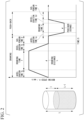
- the method of continuously casting a Cu-Zn-Si based alloy of the present embodiment has, as shown in Fig. 2 , a configuration of repeatedly carrying out an intermittent drawing cycle consisting of a drawing step of moving the solidified cast wire rod 1 in the mold 21 in the drawing direction, and a push-back step of moving the cast wire rod 1 toward an opposite side to the drawing direction.
- a pattern diagram of the intermittent drawing cycle shown in Fig. 2 is described as a set value, and in the practical continuous casting apparatus 10, the pattern diagram may be partially curved because of mechanical loss or the like.
- the pattern of the intermittent drawing cycle is appropriately set to adjust the casting speed of the cast wire rod 1.
- a graph relating to Time (s) - Moving speed (drawing speed) V (mm/s) in Fig. 2 shows one cycle of the drawing step and the push-back step.
- the drawing step includes an acceleration time Ta (s) for accelerating the drawing speed in the drawing direction from 0 (mm/s) to a predetermined speed (maximum speed) (mm/s), a drawing time T (s) for drawing the cast wire rod 1 at a constant predetermined speed (mm/s), a deceleration time Td (s) for drawing the cast wire rod 1 while decelerating the drawing speed from the predetermined speed (mm/s) to 0 (mm/s), and a suspension time D (s) for suspending drawing the cast wire rod 1.
- a drawing distance L is calculated by the following Equation (1).
- Ta s + T s + Td s + T s ⁇ Predetermined speed mm / s / 2 L mm
- the push-back step includes an acceleration time ta (s) for accelerating the drawing speed in a reverse direction to the drawing direction from 0 (mm/s) to a predetermined speed (maximum speed) (mm/s), a drawing time (push-back time) t (s) for drawing the cast wire rod 1 in the reverse direction to the drawing direction at a constant predetermined speed (mm/s), a deceleration time td (s) for drawing the cast wire rod 1 in the reverse direction to the drawing direction while decelerating the drawing speed from the predetermined speed (mm/s) to 0 (mm/s), and a suspension time d (s) for suspending drawing the cast wire rod 1.
- a push-back distance 1 is calculated by the following Equation (2).
- the cast wire rod 1 is moved in the drawing direction F in the drawing step, thereby the copper melt in the casting furnace 11 flowing into the mold 21.
- the copper melt in the mold 21 is cooled and solidified to form a solidified shell.
- the cast wire rod 1 is moved again in the drawing direction F through the drawing step.
- the rod-shaped cast wire rod 1 is continuously produced by repeating the intermittent drawing cycle in this way.
- the casting temperature is preferably within a range of 970°C or higher and 1180°C or lower.
- the fluidity of the copper melt can be ensured, the occurrence of misrun can be prevented, and the generation of a deep oscillation mark, internal defect, and altered layer can be prevented.
- seizure between the solidified shell and the casting mold can be prevented.
- the above-mentioned altered layer is due to segregation of Zn and Si, and is often observed around an oscillation. In a case in which the altered layer is locally and deeply present, the altered layer causes an adverse effect such as scuffing during drawing.
- the lower limit of the casting temperature is preferably 980°C or higher, and more preferably 1000°C or higher.
- the upper limit of the casting temperature is preferably 1150°C or lower, and more preferably 1100°C or lower.
- the casting speed is preferably within a range of 0.43 m/min or more and 3.10 m/min or less.
- the casting speed is calculated by the following Equation (3).
- L mm + 1 mm / 1000 / Ta s + T s + Td s + D s + ta s + t s + td s + d s / 60 Casting speed m / mim
- the lower limit of the casting speed is preferably 0.80 m/min or more, and more preferably 1.00 m/min or more.
- the upper limit of the casting speed is preferably 3.00 m/min or less, and more preferably 2.80 m/min or less.
- the wire rod of a Cu-Zn-Si based alloy obtained by up-drawing continuous casting according to the present embodiment is produced.
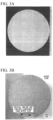
- Figs. 3A and 3B show a cross-sectional macrostructure of a cast wire rod made of a Cu-Zn-Si based alloy.
- the continuous cast wire rod cast by a horizontal continuous casting apparatus as shown in Fig. 3B , crystal grains at a lower portion are coarsened because of the influence of gravity.
- the wire rod of a Cu-Zr-Si alloy obtained by up-drawing continuous casting of the present embodiment as shown in Fig. 3A , the crystal structure is uniform.
- the wire rod of a Cu-Zn-Si based alloy obtained by up-drawing continuous casting of the present embodiment which is configured as described above, since the amount of Cu is within a range of 75.0 mass% or more and 76.9 mass% or less, the amount of Si is within a range of 2.6 mass% or more and 3.1 mass% or less, the amount of Zr is within a range of 0.003 mass% or more and 0.20 mass% or less, the amount of P is within a range of 0.02 mass% or more and 0.15 mass% or less, the Zr-P compound containing Zr and P is produced, and the primary crystal ⁇ -phase is crystallized by using this Zr-P compound as an inoculant nucleus; thereby, it is possible to prevent dendrites from being coarsened.
- the number density of the Zr-P compound containing Zr and P is within a range of 1500 pieces/mm 2 or more and 7000 pieces/mm 2 or less, the effect of preventing the dendrites from being coarsened, which is caused by the Zr-P compound, can be sufficiently achieved.
- the mass ratio Zr/P of Zr to P is less than 1.9 or more than 4.2 and the mass ratio Cu/Si of Cu to Si is more than 25
- excessive production of the Zr-P compound can be prevented, and primary crystal ⁇ -phases can be prevented from being bonded to each other to be coarsened, thereby reducing the deterioration of mechanical properties.
- a decrease in workability caused by the Zr-P compound can be surely prevented.
- the ductility is sufficiently obtained, and cold workability is particularly excellent.
- the obtained continuous cast wire rod can be favorably processed by cold drawing or other work.
- the present invention is not limited thereto, and can be appropriately modified without departing from the technical idea of the invention.
- the present invention may be to provide an up-drawing continuous cast wire rod having a polygonal cross-section, or an up-drawing continuous cast wire rod having a tubular cross-section.
- the present invention may be to provide a wire rod obtained by up-drawing continuous casting, which has a deformed shape with a protruding portion and a recessed portion in a cross-section.
- the cross-sectional area of the cross-section orthogonal to the longitudinal direction is not also particularly limited.
- the structure of the casting mold is not limited, and for example, a casting mold with a water-cooling probe that is formed of a double tube and that is inserted in the mold may be adopted.
- the material of the mold 21 is graphite
- boron nitride having a self-lubricating property similar to graphite may be used.
- Melting raw materials were prepared to have compositions shown in Table 1. Each of the prepared melting raw materials was put into the crucible 12 of the casting furnace 11 shown in Fig. 1 in an amount of 500 kg, and heated by heating means to be melted.
- a mold for producing a cast wire rod having an outer diameter of 6 mm (28.26 mm 2 of cross-sectional area of the cross-section orthogonal to the drawing direction) and a circular cross-section was prepared.
- each of cast wire rods was drawn out according to an intermittent drawing cycle shown in Table 2 to be cast by 300 kg.
- Each of the obtained cast wire rod was cut along the center line parallel to a drawing direction to prepare a sample for microstructure observation, which is used for observing an oscillation and internal defects.
- the sample was cut perpendicular to the drawing direction to prepare a sample for microstructure observation, which is used for observing dendrites.
- the cast wire rod was cut perpendicular to the drawing direction to obtain a sample for EPMA measurement.
- samples were immersed in an etching solution (a mixed solution of a hydrogen peroxide solution and ammonia water) at 30°C to 40°C and washed by ultrasonic washing for 30 to 60 s.
- samples were immersed in water at room temperature, washed by ultrasonic washing for 30 to 60 s, and dried.
- EPMA measurement was performed on samples for EPMA measurement thus obtained as described above, and a dispersion status of the Zr-P compound was observed.
- An observation visual field was 69 ⁇ m ⁇ 49 ⁇ m, and the measurement was performed once at the substantially center position of each sample for EPMA measurement.
- the various conditions for EPMA measurement were set as follows.
- Zr and P each had a detection intensity of level 3 or higher, and granular compounds each of which a diameter in a size of 1 ⁇ m or more and 3 ⁇ m or less were determined as Zr-P compounds.
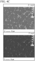
- Figs. 4A to 4C show examples of the EPMA measurement results. It is confirmed that the Zr-P compounds were present in a larger amount in Comparative Example 2 shown in Fig. 4B and Comparative Example 3 shown in Fig. 4C as compared with Example 12 of the present invention shown in Fig. 4A .
- the samples for microstructure observation obtained as described above were observed with an optical microscope to evaluate the crystal structure, the oscillation depth, internal defects, and an altered layer.
- Figs. 5A to 5C show examples of the observation results of the crystal structures.
- Comparative Example 1 shown in Fig. 5B it was confirmed that very coarsened dendrites were grown.
- Comparative Example 3 shown in Fig. 5C a coarse granular structure was obtained.
- Example 12 of the present invention shown in Fig. 5A a fine dendrite structure was obtained.
- Each of the obtained cast wire rods was cut along the center line in parallel with the drawing direction.
- the above-mentioned sample was subjected to emery polishing in the order of #240, 400, 800, and 1500 at a pressure of 100 N and a speed of 100 r/min for 1000 s in each case.
- buff polishing was carried out in the order of particles with a size of 9 ⁇ m, 3 ⁇ m, and 1 ⁇ m at a pressure of 30 N and a speed of 100 r/min for 1000 s in each case.
- samples were immersed in an etching solution (a mixed solution of a hydrogen peroxide solution and ammonia water) at 30°C to 40°C and washed by ultrasonic washing for 30 to 60 s.
- samples were immersed in water at room temperature, washed by ultrasonic washing for 30 to 60 s, and dried.
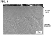
- a superficial layer of the sample was observed (because the altered layer exists on the superficial layer) with EPMA under the following conditions, and a region where Zn and Si are segregated and the dendrite structure is not formed was determined as an altered layer through microscopic observation.
- a line is drawn along the drawing direction from an altered layer with the deepest part (that is, the part exists in the innermost location of a cast wire in the altered layer region) to the superficial layer, and the obtained line length is determined as a thickness of the altered layer.
- thicknesses of the altered layers formed on the superficial layer of an ingot were measured. Then, an altered layer having a thickness of less than 100 ⁇ m was evaluated as "B", and an altered layer having a thickness of 100 ⁇ m or more was evaluated as "C”.
- the cold workability of the obtained cast wire rods was evaluated as follows.
- a cast wire rod having a diameter of ⁇ 6 mm was peeled to obtain a diameter of ⁇ 5.6 mm.
- This cast wire rod was subjected to cold drawing with a multi-pass, and a wire diameter that was able to be drawn was confirmed (disconnection status during cold drawing).
- a cast wire rod having a diameter of ⁇ 6 mm was peeled to obtain a diameter of ⁇ 5.6 mm.
- This cast wire rod was subjected to cold drawing with one pass, and a wire diameter that was able to be drawn was confirmed (disconnection status in one pass).
- the cast wire rod that was able to be drawn in a range of ⁇ 5.6 mm to ⁇ 4.6 mm was evaluated as "A”
- the cast wire rod that was able to be drawn in a range of ⁇ 5.6 mm to ⁇ 4.8 mm was evaluated as "B”
- the cast wire rod that was not able to be drawn in a range of ⁇ 5.6 mm to ⁇ 4.8 mm was evaluated as "C”.
- Each of the cast wire rods in Examples 1 to 13 and Comparative Examples 1 to 4 was subjected to a test, and the results are shown in Table 3.
- the obtained cast wire rod having a diameter of ⁇ 6 mm was cut to a length of 150 mm, a tensile test was performed by using a tensile tester AG-100kNX under conditions of a distance between grips of 70 mm, a distance between gauge points of 50 mm, and a tensile speed of 15 MPa/sec, and the tensile strength and the elongation were evaluated (tensile strength and elongation of cast wire).
- the obtained cast wire rod having a diameter of ⁇ 6 mm was peeled to be a diameter of ⁇ 5.8 mm, cold drawing work was carried out until the diameter became ⁇ 5.5 mm, heat treatment was then performed at 580°C ⁇ 1 hour, and cold drawing work was further performed until the diameter became ⁇ 5.0 mm.
- the drawn wire rod having a diameter of ⁇ 5.0 mm was cut to be a length of 150 mm, and the tensile test was performed under the above conditions to evaluate the tensile strength and the elongation (tensile strength and elongation of the machined wire rod).
- the wire rod of a Cu-Zn-Si based alloy obtained by up-drawing continuous casting which enables casting defects to less likely occur and enables the occurrence of coarsened dendrites to be prevented, and which is excellent in cold workability can be provided.
Landscapes
- Engineering & Computer Science (AREA)
- Mechanical Engineering (AREA)
- Chemical & Material Sciences (AREA)
- Materials Engineering (AREA)
- Metallurgy (AREA)
- Organic Chemistry (AREA)
- Continuous Casting (AREA)
Abstract
Description
- The present invention relates to a wire rod of a Cu-Zn-Si based alloy obtained by up-drawing continuous casting, the wire rod being drawn upward and being subjected to continuous casting.
- Priority is claimed on
Japanese Patent Application No. 2020-082545, filed May 8, 2020 - In the related art, free-cutting brass as a copper alloy having excellent machinability has been widely used as a material of various parts such as a water contact metal fitting (for example, water faucet fittings of water supply pipe, valves, cocks, joints, flanges, faucet fittings, in-house built device, water discharging tools, joint clip, boiler parts, or the like) used continuously or temporarily in contact with water (tap water or the like), a friction engaging member (for example, bearing, gear, cylinder, bearing retainer, impeller, pump parts, bearing or the like) making a relative movement to a facing member (rotating shaft or the like) continuously or temporarily in contact with the facing member or the like, or a structural material thereof.
- Pb has been added to a Cu-Zn alloy to improve machinability of the above-mentioned free-cutting brass. However, in recent years, the use of Pb has been restricted from the viewpoint of environmental problems and other issues, and the application thereof is significantly restricted.
- Therefore, for example, a Cu-Zn-Si based alloy disclosed in
Patent Document 1 has been provided as a copper alloy having excellent machinability even though the amount of Pb is significantly reduced. Since this Cu-Zn-Si based alloy does not contain Pb, the Cu-Zn-Si based alloy can be used for various parts such as water faucet fittings of water supply pipe, water supply and drainage fittings, valves, and water meter fittings, with which drinking water is brought into contact. - In a case of manufacturing such parts, rods and wire rods having various cross-sections may be used as processing materials.
- In a case of manufacturing rods and wire rods, the rods and wire rods are usually manufactured by carrying out hot extrusion or rolling on large ingots to make rods, and these rods are subjected to plastic working such as drawing working. However, in the case in which rods are manufactured by hot extrusion or rolling, it is necessary to carry out various steps such as a casting step of producing a large ingot, a heating step of heating the ingot, and an extrusion step of extruding the heated ingot or a rolling step, which requires a large amount of manufacturing cost and manufacturing time.
- Therefore, as a method of efficiently producing a metal rod or wire rod at low cost, for example, a continuous casting method of installing a casting mold in a casting furnace in which the metal melt is stored, and continuously casting a cast wire rod is provided as disclosed in
Patent Documents 2 to 5. In the above-mentioned casting mold, a mold having a self-lubricating property such as graphite is usually used. - In the case of continuously casting a cast wire rod, as shown in
Patent Documents 2 to 5, it is common to repeat an intermittent drawing cycle in which a drawing step and a push-back step are repeatedly performed without continuously drawing the cast wire rod at a constant speed. In a case in which the intermittent drawing cycle is carried out in this way, a solid phase (solidified shell) that has been solidified during the drawing is moved, a liquid phase flows into a space after the movement, and a new solid phase is formed. Since the solidified shell is formed intermittently in this way, a pattern, called an oscillation mark, is formed on a surface of the cast wire rod in synchronization with the period of the intermittent drawing cycle. -
- [Patent Document 1]
Japanese Patent (Granted) Publication No. 4095666 - [Patent Document 2]
Japanese Unexamined Patent Application, First Publication No. H05-169197 - [Patent Document 3]
Japanese Unexamined Patent Application, First Publication No. H08-168852 - [Patent Document 4]
Japanese Unexamined Patent Application, First Publication No. H05-031561 - [Patent Document 5]
Japanese Unexamined Patent Application, First Publication No. 2014-091147 - In the case of carrying out continuous casting on the Cu-Zn-Si alloy disclosed in
Patent Document 1, a horizontal continuous casting apparatus from which a cast wire rod is drawn in a horizontal direction and a vertical continuous casting apparatus from which a cast wire rod is drawn downward in a vertical direction are usually used. - In the above-mentioned horizontal continuous casting apparatus and vertical continuous casting apparatus, there is a problem that a large site is required in a case in which equipment is installed, resulting in an increase in installation cost. In addition, there are problems that it is necessary to discard the metal melt in the casting furnace in a case in which a product type is switched during the casting, and the product type cannot be easily switched.
- Here, in an up-drawing casting apparatus that includes a casting mold attached on an upper side of a casting furnace, and that draws a cast wire rod up in the vertical direction, an equipment configuration is relatively simple, and installation cost can be reduced. In a case of switching a product type, the casting furnace on which the casting mold is attached may be changed, which is suitable for small amount and various type production.
- However, in a case in which continuous casting is carried out to produce a cast wire rod made of the Cu-Zn-Si based alloy disclosed in
Patent Document 1 by using the up-drawing casting apparatus, the casting mold is not sufficiently filled with the metal melt, and casting defects such as sink marks may occur. In addition, the oscillation mark may be deeper. Furthermore, coarsened dendrites are likely to be generated, and cold workability may be deteriorated. - Therefore, the Cu-Zn-Si based alloy was not stably cast by the up-drawing casting apparatus.
- The present invention has been made against the background of the above circumstances, and an objective is to provide a wire rod of a Cu-Zn-Si based alloy obtained by up-drawing continuous casting, which enables casting defects to less likely occur and enables the occurrence of coarsened dendrites to be prevented, and which is excellent in cold workability.
- In order to solve this problem, a wire rod of a Cu-Zn-Si based alloy obtained by up-drawing continuous casting of the present invention is provided. The Cu-Zn-Si based alloy contains Cu, Zn, and Si, an amount of Cu is within a range of 75.0 mass% or more and 76.9 mass% or less, an amount of Si is within a range of 2.6 mass% or more and 3.1 mass% or less, an amount of Zr is within a range of 0.003 mass% or more and 0.20 mass% or less, an amount of P is within a range of 0.02 mass% or more and 0.15 mass% or less, a balance is composed of Zn and inevitable impurities, and a number density of a Zr-P compound containing Zr and P is within a range of 1500 pieces/mm2 or more and 7000 pieces/mm2 or less.
- In the wire rod of a Cu-Zn-Si based alloy obtained by up-drawing continuous casting with this configuration, since the amount of Cu is within a range of 75.0 mass% or more and 76.9 mass% or less, and the amount of Si is within a range of 2.6 mass% or more and 3.1 mass% or less, an α-phase is generated as a primary crystal.
- Since the amount of Zr is within a range of 0.003 mass% or more and 0.20 mass% or less, and the amount of P is within a range of 0.02 mass% or more and 0.15 mass% or less, the Zr-P compound containing Zr and P is produced, and a primary crystal α-phase is crystallized by using this Zr-P compound as an inoculant nucleus; thereby, it is possible to prevent dendrites from being coarsened.
- Furthermore, since the number density of the Zr-P compound containing Zr and P is within a range of 1500 pieces/mm2 or more and 7000 pieces/mm2 or less, the effect of preventing the dendrites from being coarsened, which is caused by the Zr-P compound, can be sufficiently achieved.
- Here, in the wire rod of a Cu-Zn-Si based alloy obtained by up-drawing continuous casting of the present invention, the mass ratio Zr/P of Zr to P is preferably less than 1.9, and the mass ratio Cu/Si of Cu to Si is preferably more than 25.
- In this case, since the mass ratio Zr/P of Zr to P is less than 1.9 and the mass ratio Cu/Si of Cu to Si is more than 25, excessive production of the Zr-P compound can be prevented, and primary crystal α-phases can be prevented from being bonded to each other to be coarsened, thereby preventing the deterioration of mechanical properties. In addition, a decrease in workability caused by the Zr-P compound can be surely prevented.
- Alternatively, in the wire rod of a Cu-Zn-Si based alloy obtained by up-drawing continuous casting of the present invention, the mass ratio Zr/P of Zr to P is preferably more than 4.2, and the mass ratio Cu/Si of Cu to Si is preferably more than 25.
- In this case, since the mass ratio Zr/P of Zr to P is more than 4.2 and the mass ratio Cu/Si of Cu to Si is more than 25, excessive production of the Zr-P compound can be prevented, and primary crystal α-phases can be prevented from being bonded to each other to be coarsened, thereby reducing the deterioration of mechanical properties. In addition, a decrease in workability caused by the Zr-P compound can be surely prevented.
- In addition, in the wire rod of a Cu-Zn-Si based alloy obtained by up-drawing continuous casting of the present invention, the tensile strength is preferably within a range of 500 N/mm2 or more and 540 N/mm2 or less, and the elongation is preferably within a range of 5% or more and 15% or less.
- In this case, since the strength and elongation are within the above ranges, the up-drawing continuous cast wire rod has sufficient ductility and is particularly excellent in cold workability.
- According to the present invention, it is possible to provide the wire rod of a Cu-Zn-Si based alloy obtained by up-drawing continuous casting, which enables casting defects to less likely occur and enables the occurrence of coarsened dendrites to be prevented, and which is excellent in cold workability.
-
-
Fig. 1 is an explanatory diagram showing an example of a continuous casting apparatus used for producing a wire rod of a Cu-Zn-Si based alloy obtained by up-drawing continuous casting according to an embodiment of the present invention. -
Fig. 2 is an explanatory diagram showing an example of a pattern of an intermittent drawing cycle in a case of producing the wire rod of a Cu-Zn-Si based alloy obtained by up-drawing continuous casting according to the embodiment of the present invention. -
Fig. 3A is a cross-sectional macrostructure of a cast wire rod of a Cu-Zn-Si based alloy, which is the wire rod obtained by up-drawing continuous casting of the present embodiment. -
Fig. 3B is a cross-sectional macrostructure of a cast wire rod made of a Cu-Zn-Si based alloy, which is a continuous cast wire rod cast by a horizontal continuous casting apparatus. -
Fig. 4A is a diagram showing measurement results of a Zr-P compound in a cast wire rod in an example (Example 12 of the present invention), which is measured by an electron probe micro analyzer (EPMA). -
Fig. 4B is a diagram showing measurement results of a Zr-P compound in a cast wire rod in an example (Comparative Example 2), which is measured by the electron probe micro analyzer (EPMA). -
Fig. 4C is a diagram showing measurement results of a Zr-P compound in a cast wire rod in an example (Comparative Example 3), which is measured by the electron probe micro analyzer (EPMA). -
Fig. 5A is a microstructure of the cast wire rod in the example (Example 12 of the present invention). -
Fig. 5B is a microstructure of the cast wire rod in the example (Comparative Example 1). -
Fig. 5C is a microstructure of the cast wire rod in the example (Comparative Example 3). -
Fig. 6A is an observation photograph showing an evaluation result of an oscillation depth in Examples, which is evaluated as "B" (oscillation depth of less than 10 µm). -
Fig. 6B is an observation photograph showing an evaluation result of an oscillation depth in Examples, which is evaluated as "C" (oscillation depth of 10 µm or more). -
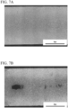
Fig. 7A is an observation photograph showing an evaluation result of an internal result in Examples, which is evaluated as "B". -
Fig. 7B is an observation photograph showing an evaluation result of the internal result in Examples, which is evaluated as "C". -
Fig. 8 is an observation photograph showing an evaluation result of an altered layer in Examples. - Hereinafter, a wire rod of a Cu-Zn-Si based alloy obtained by up-drawing continuous casting according to an embodiment of the present invention will be described.
- Here, the wire rod of a Cu-Zn-Si based alloy obtained by up-drawing continuous casting of the present embodiment has a circular cross-section orthogonal to the longitudinal direction, and a cross-sectional area of the cross-section is within a range of 15 mm2 or more and 500 mm2 or less.
- The wire rod of a Cu-Zn-Si based alloy obtained by up-drawing continuous casting of the present embodiment has a composition in which an amount of Cu is within a range of 75.0 mass% or more and 76.9 mass% or less, an amount of Si is within a range of 2.6 mass% or more and 3.1 mass% or less, an amount of Zr is within a range of 0.003 mass% or more and 0.20 mass% or less, an amount of P is within a range of 0.02 mass% or more and 0.15 mass% or less, and a balance is composed of Zn and inevitable impurities.
- In addition, the wire rod of a Cu-Zn-Si based alloy obtained by up-drawing continuous casting of the present embodiment has a number density of a Zr-P compound containing Zr and P within a range of 1500 pieces/mm2 or more and 7000 pieces/mm2 or less.
- Here, in the present embodiment, the mass ratio Zr/P of Zr to P is preferably less than 1.9, or the mass ratio Zr/P of Zr to P is preferably more than 4.2, and the mass ratio Cu/Si of Cu to Si is preferably more than 25.
- In addition, in the present embodiment, the tensile strength is preferably within a range of 500 N/mm2 or more and 540 N/mm2 or less, and the elongation is preferably within a range of 5% or more and 15% or less.
- Next, the reason why the composition, the number density of the Zr-P compound, and the feature are defined as described above will be described.
- Zr is co-added with P, thereby producing the Zr-P compound containing Zr and P. These Zr-P compound particles are used as inoculant nuclei to form a primary crystal α-phase, resulting in fine dendrite formation and granular crystallization of the α-phase crystallized during solidification. However, since Zr has a strong affinity for oxygen, Zr oxide and other substances are likely to be generated. As a result, the viscosity of the metal melt increases, and defects such as oxides are likely to occur during casting. In addition, blow holes and microporosities are likely to occur.
- Therefore, in the present embodiment, the amount of Zr is set within a range of 0.003 mass% or more and 0.20 mass% or less.
- In order to surely produce the Zr-P compound, the lower limit of the amount of Zr is preferably 0.004 mass% or more, and still more preferably 0.005 mass% or more. By contrast, in order to suppress the production of Zr oxide, the upper limit of the amount of Zr is preferably 0.18 mass% or less, and still more preferably 0.16 mass% or less.
- As described above, P is co-added with Zr to produce a Zr-P compound containing Zr and P, and the Zr-P compound particles are used as an inoculant nucleus to form a primary crystal α-phase. As a result, fine dendrite formation and granular crystallization can be achieved. In a case in which a large amount of P is contained, cracks are likely to occur on a surface or the inside of an ingot during the formation of the ingot, and disconnection is likely to occur during working.
- Therefore, in the present embodiment, the amount of P is set within a range of 0.02 mass% or more and 0.15 mass% or less.
- In order to surely produce the Zr-P compound, the lower limit of the amount of P is preferably 0.03 mass% or more, and still more preferably 0.08 mass% or more. By contrast, in order to prevent crack occurrence, the upper limit of the amount of P is preferably 0.13 mass% or less, and still more preferably 0.10 mass% or less.
- As described above, the Zr-P compound particles are used as inoculant nuclei to form the primary crystal α-phase, resulting in fine dendrite formation and granular crystallization of the crystallized α-phase.
- Here, a Cu concentration is set to 75.0 mass% or more, and a Si concentration is relatively lowered to obtain a region of the primary crystal α-phase, and fine dendrite formation and granular crystallization can be achieved. By contrast, in a case in which the Cu concentration is more than 76.9 mass%, the primary crystal α-phases (granular crystal grains) are bonded to each other, resulting in the same state as growth of dendrite arms. Furthermore, there is a problem on a casting surface on which blow holes and sink marks with a large amount and large size are produced because of bonds between crystal grains. Furthermore, as the Cu concentration increases, the strength may decrease.
- Therefore, in the present embodiment, the amount of Cu is set within a range of 75.0 mass% or more and 76.9 mass% or less.
- In order to surely produce the primary crystal α-phase, the lower limit of the amount of Cu is preferably 75.5 mass% or more, and still more preferably 75.8 mass% or more. By contrast, in order to prevent the bonds between the primary crystal α-phases (granular crystal grains), the upper limit of the amount of Cu is preferably 76.8 mass% or less, and still more preferably 76.7 mass% or less.
- Si is an element having a function of improving machinability. Si also has functions of improving mechanical properties such as tensile strength, proof stress, impact strength, and fatigue strength. Furthermore, Si has a function of improving fluidity of the metal melt, preventing oxidation of the metal melt, and lowering a melting point. However, in a case in which the amount of Si is too large, a β phase is formed as a primary crystal, and fine dendrite formation and granular crystallization may not be achieved. In terms of castability, in the case in which the amount of Si is too large, the thermal conductivity is lowered, and internal defects are likely to occur in the cast wire rod.
- Therefore, in the present embodiment, the amount of Si is set within a range of 2.6 mass% or more and 3.1 mass% or less.
- In order to further improve the mechanical properties, the lower limit of the amount of Si is preferably 2.7 mass% or more, and still more preferably 2.8 mass% or more. By contrast, in order to surely form the primary crystal α-phase, the upper limit of the amount of Si is preferably 3.05 mass% or less, and still more preferably 3.00 mass% or less.
- As described above, the Zr-P compound is used as an inoculant nucleus to form a primary crystal α-phase, resulting in fine dendrite formation and granular crystallization of the α-phase crystallized during solidification. However, in a case in which the amount of the Zr-P compound is too large, the primary crystal α-phases (granular crystal grains) are bonded to each other, resulting in the same state as coarsened dendrites in which dendrite arms are grown. In addition, a large number of crystals may be produced at crystalline grain boundaries from the Zr-P compound not to become inoculant nuclei to promote stress concentration during plastic working, which may reduce ductility.
- Therefore, in the present embodiment, the number density of the Zr-P compound is set within a range of 1500 pieces/mm2 or more and 7000 pieces/mm2 or less.
- In order to ensure fine dendrite formation and granular crystallization to be effective, the lower limit of the number density of the Zr-P compound is preferably 2500 pieces/mm2 or more, and still more preferably 3500 pieces/mm2 or more. By contrast, in order to further prevent the bonds between the primary crystal α-phases (granular crystal grains), the upper limit of the number density of the Zr-P compound is preferably 6500 pieces/mm2 or less, and still more preferably 4500 pieces/mm2 or less.
- Zr and P are co-added for the purpose of forming fine dendrites of copper alloy crystal grains. Each of Zr and P can only slightly fine copper alloy crystal grains in the same manner as other general additive elements, but in a case in which Zr and P coexist in an appropriate range, fine dendrites can be effectively formed. However, in the case in which the amount of the Zr-P compound is too large, the primary crystal α-phases (granular crystal grains) are bonded to each other, resulting in the same state as coarsened dendrites in which dendrite arms are grown.
- Here, in the case of carrying out the up-drawing continuous cast, it is possible to suppress the excessive production of the Zr-P compound in a case in which the mass ratio Cu/Si of Cu to Si is more than 25 and the mass ratio Zr/P of Zr to P is less than 1.9 or more than 4.2.
- The upper limit of the mass ratio Cu/Si of Cu to Si is preferably 25.5 or more, and still preferably 25.8 or more. The upper limit of the mass ratio Cu/Si of Cu to Si is not particularly limited, but is preferably 29 or less, and still more preferably 27 or less.
- In addition, the mass ratio Zr/P of Zr to P is preferably less than 1.8, and more preferably less than 1.4. The mass ratio Zr/P preferably has a lower limit value of 0.04 or more and more preferably has a lower limit value of 0.10 or more, with respect to an upper limit value of less than 1.8.
- Alternatively, the mass ratio Zr/P of Zr to P is preferably more than 4.5, and still more preferably more than 4.8. The mass ratio Zr/P preferably has an upper limit value of 5.4 or less and more preferably has an upper limit value of 5.1 or less, with respect to a lower limit value of more than 4.5.
- In the cast wire rod, a balance between strength and elongation is important for cold drawability, and in a case in which the strength is too large, the elongation important for cold drawability decreases.
- Therefore, in the present embodiment, in a case in which the tensile strength is within a range of 500 N/mm2 or more and 540 N/mm2 or less and the elongation is within a range of 5% or more and 15% or less, the cold drawability can be sufficiently improved.
- The lower limit of the tensile strength is preferably 510 N/mm 2 or more, and still more preferably 525 N/mm2 or more. On the other hand, the upper limit of the tensile strength is preferably 535 N/mm 2 or less, and still more preferably 530 N/mm2 or less.
- In addition, the lower limit of the elongation is preferably 6% or more, and still more preferably 7% or more. On the other hand, the upper limit of the elongation is preferably 14% or less, and still more preferably 13% or less.
- Next, a
continuous casting apparatus 10 used for producing a wire rod of a Cu-Zn-Si based alloy obtained by up-drawing continuous casting according to the present embodiment will be described with reference toFig. 1 . - This
continuous casting apparatus 10 includes a castingfurnace 11, acontinuous casting mold 20 connected to the castingfurnace 11, and pinch rolls 17 for drawing acast wire rod 1 produced in thecontinuous casting mold 20. - The casting
furnace 11 heats and melts a melting raw material to produce and store a copper melt having a predetermined composition, and is provided with acrucible 12 that stores the melting raw material and the copper melt, and heating means (not shown) for heating thecrucible 12. - The
cast wire rod 1 produced in thecontinuous casting mold 20 is interposed between the pinch rolls 17 that draws thecast wire rod 1 out in a drawing direction F. - In the present embodiment, the
cast wire rod 1 is intermittently drawn out. - The
continuous casting mold 20 is provided with acylindrical mold 21 into which the supplied copper melt is injected, and a coolingpart 28 for cooling themold 21. - Here, in the present embodiment, as shown in
Fig. 1 , thecontinuous casting mold 20 is disposed on the copper melt in the castingfurnace 11 so that afireproof insulation material 15 is interposed between thecontinuous casting mold 20 and the copper melt, and thecast wire rod 1 is configured to be drawn out upward. - The
mold 21 has a substantially cylindrical shape, and is provided with acasting hole 24 penetrating from one side to the other side. - The cooling
part 28 is a water-cooling jacket arranged on an outer peripheral side of themold 21, and is configured to circulate cooling water to cool themold 21. - Next, a method of producing the wire rod of a Cu-Zn-Si based alloy obtained by up-drawing continuous casting according to the present embodiment by using the above-mentioned
continuous casting apparatus 10 will be described. - First, a melting raw material is charged into the
crucible 12 through a raw material input port of the castingfurnace 11. As the raw material, a Cu single substance and a Zn single substance, or a Si single substance, a Cu-Zn mother alloy, a Cu-Si mother alloy and other alloys can be used. In addition, the raw material containing Zn and Si may be dissolved together with a copper raw material. Furthermore, a recycled material and a scrap material of the present alloy may be used. - Next, the melting raw material charged in the
crucible 12 is heated to be melted by the heating means to produce the copper melt prepared to have the above-mentioned component composition. - The copper melt is heated in the
crucible 12 to a predetermined casting temperature and is stored. Then, this copper melt is supplied to thecontinuous casting mold 20. - The copper melt supplied into the
continuous casting mold 20 is cooled in themold 21, solidified, and becomes thecast wire rod 1. Thecast wire rod 1 is intermittently drawn out with the pinch rolls 17 to produce thecast wire rod 1 continuously. - The method of continuously casting a Cu-Zn-Si based alloy of the present embodiment has, as shown in
Fig. 2 , a configuration of repeatedly carrying out an intermittent drawing cycle consisting of a drawing step of moving the solidifiedcast wire rod 1 in themold 21 in the drawing direction, and a push-back step of moving thecast wire rod 1 toward an opposite side to the drawing direction. - A pattern diagram of the intermittent drawing cycle shown in
Fig. 2 is described as a set value, and in the practicalcontinuous casting apparatus 10, the pattern diagram may be partially curved because of mechanical loss or the like. - The pattern of the intermittent drawing cycle is appropriately set to adjust the casting speed of the
cast wire rod 1. - A graph relating to Time (s) - Moving speed (drawing speed) V (mm/s) in
Fig. 2 shows one cycle of the drawing step and the push-back step. The drawing step includes an acceleration time Ta (s) for accelerating the drawing speed in the drawing direction from 0 (mm/s) to a predetermined speed (maximum speed) (mm/s), a drawing time T (s) for drawing thecast wire rod 1 at a constant predetermined speed (mm/s), a deceleration time Td (s) for drawing thecast wire rod 1 while decelerating the drawing speed from the predetermined speed (mm/s) to 0 (mm/s), and a suspension time D (s) for suspending drawing thecast wire rod 1. A drawing distance L is calculated by the following Equation (1).
- The push-back step includes an acceleration time ta (s) for accelerating the drawing speed in a reverse direction to the drawing direction from 0 (mm/s) to a predetermined speed (maximum speed) (mm/s), a drawing time (push-back time) t (s) for drawing the
cast wire rod 1 in the reverse direction to the drawing direction at a constant predetermined speed (mm/s), a deceleration time td (s) for drawing thecast wire rod 1 in the reverse direction to the drawing direction while decelerating the drawing speed from the predetermined speed (mm/s) to 0 (mm/s), and a suspension time d (s) for suspending drawing thecast wire rod 1. A push-back distance 1 is calculated by the following Equation (2).
- In the push-back step, since the
cast wire rod 1 is drawn out in the reverse direction to the drawing direction, the speed is marked with "-". - Next, a solidification state in the
mold 21 in a case in which the intermittent drawing cycle is repeated as described above will be described. - First, the
cast wire rod 1 is moved in the drawing direction F in the drawing step, thereby the copper melt in the castingfurnace 11 flowing into themold 21. - Next, the copper melt in the
mold 21 is cooled and solidified to form a solidified shell. - Then, seizure between the solidified shell and the
mold 21 is prevented through the push-back step, and the solidified shell that has been formed one cycle before and a solidified shell that is formed in this cycle are bonded. - After the solidified shell is formed to have a sufficient thickness in the
mold 21, thecast wire rod 1 is moved again in the drawing direction F through the drawing step. - As described above, the rod-shaped
cast wire rod 1 is continuously produced by repeating the intermittent drawing cycle in this way. - Here, the casting temperature is preferably within a range of 970°C or higher and 1180°C or lower. As a result of setting the casting temperature to 970°C or higher, the fluidity of the copper melt can be ensured, the occurrence of misrun can be prevented, and the generation of a deep oscillation mark, internal defect, and altered layer can be prevented. On the other hand, as a result of setting the casting temperature to 1180°C or lower, seizure between the solidified shell and the casting mold can be prevented. The above-mentioned altered layer is due to segregation of Zn and Si, and is often observed around an oscillation. In a case in which the altered layer is locally and deeply present, the altered layer causes an adverse effect such as scuffing during drawing.
- The lower limit of the casting temperature is preferably 980°C or higher, and more preferably 1000°C or higher. On the other hand, the upper limit of the casting temperature is preferably 1150°C or lower, and more preferably 1100°C or lower.
- The casting speed is preferably within a range of 0.43 m/min or more and 3.10 m/min or less.
- The casting speed is calculated by the following Equation (3).

- As a result of setting the casting speed to 0.43 m/min or more, a solidification speed can be ensured, the coalescence of crystal grains can be prevented, and the crystal grains can be further miniaturized. In addition, an early increase in a solid phase rate can be prevented, the occurrence of misrun can be prevented, and the generation of deep oscillation marks, internal defects, and altered layers can be prevented. On the other hand, as a result of setting the casting speed to 3.10 m/min or less, insufficient supply of the metal melt during drawing can be prevented, and the generation of deep oscillation marks, internal defects, and altered layers can be prevented.
- The lower limit of the casting speed is preferably 0.80 m/min or more, and more preferably 1.00 m/min or more. On the other hand, the upper limit of the casting speed is preferably 3.00 m/min or less, and more preferably 2.80 m/min or less.
- As described above, the wire rod of a Cu-Zn-Si based alloy obtained by up-drawing continuous casting according to the present embodiment is produced.
- Here,
Figs. 3A and 3B show a cross-sectional macrostructure of a cast wire rod made of a Cu-Zn-Si based alloy. In the continuous cast wire rod cast by a horizontal continuous casting apparatus, as shown inFig. 3B , crystal grains at a lower portion are coarsened because of the influence of gravity. By contrast, in the wire rod of a Cu-Zr-Si alloy obtained by up-drawing continuous casting of the present embodiment, as shown inFig. 3A , the crystal structure is uniform. - According to the wire rod of a Cu-Zn-Si based alloy obtained by up-drawing continuous casting of the present embodiment, which is configured as described above, since the amount of Cu is within a range of 75.0 mass% or more and 76.9 mass% or less, the amount of Si is within a range of 2.6 mass% or more and 3.1 mass% or less, the amount of Zr is within a range of 0.003 mass% or more and 0.20 mass% or less, the amount of P is within a range of 0.02 mass% or more and 0.15 mass% or less, the Zr-P compound containing Zr and P is produced, and the primary crystal α-phase is crystallized by using this Zr-P compound as an inoculant nucleus; thereby, it is possible to prevent dendrites from being coarsened.
- In addition, since the number density of the Zr-P compound containing Zr and P is within a range of 1500 pieces/mm2 or more and 7000 pieces/mm2 or less, the effect of preventing the dendrites from being coarsened, which is caused by the Zr-P compound, can be sufficiently achieved.
- In addition, in the present embodiment, in a case in which the mass ratio Zr/P of Zr to P is less than 1.9 or more than 4.2 and the mass ratio Cu/Si of Cu to Si is more than 25, excessive production of the Zr-P compound can be prevented, and primary crystal α-phases can be prevented from being bonded to each other to be coarsened, thereby reducing the deterioration of mechanical properties. In addition, a decrease in workability caused by the Zr-P compound can be surely prevented.
- Furthermore, in the present embodiment, in a case in which the tensile strength is within a range of 500 N/mm2 or more and 540 N/mm2 or less and the elongation is within a range of 5% or more and 15% or less, the ductility is sufficiently obtained, and cold workability is particularly excellent.
- Thus, the obtained continuous cast wire rod can be favorably processed by cold drawing or other work.
- Although the wire rod of a Cu-Zn-Si based alloy obtained by up-drawing continuous casting according to the embodiment of the present invention is described above, the present invention is not limited thereto, and can be appropriately modified without departing from the technical idea of the invention.
- For example, in the present embodiment, it has been described to produce the wire rod obtained by up-drawing continuous casting, which has the circular cross-section and the cross-sectional area within a range of 15 mm2 or more and 500 mm2 or less, but the present invention is not limited thereto, and the present invention may be to provide an up-drawing continuous cast wire rod having a polygonal cross-section, or an up-drawing continuous cast wire rod having a tubular cross-section. In addition, the present invention may be to provide a wire rod obtained by up-drawing continuous casting, which has a deformed shape with a protruding portion and a recessed portion in a cross-section. Furthermore, the cross-sectional area of the cross-section orthogonal to the longitudinal direction is not also particularly limited.
- Furthermore, in the above-mentioned present embodiment, although the casting mold provided with the cooling jacket has been described embodiment, the structure of the casting mold is not limited, and for example, a casting mold with a water-cooling probe that is formed of a double tube and that is inserted in the mold may be adopted.
- Furthermore, in the present embodiment, although the material of the
mold 21 is graphite, boron nitride having a self-lubricating property similar to graphite may be used. - The results of a confirmation experiment conducted to confirm the effect of the present invention will be described below.
- Melting raw materials were prepared to have compositions shown in Table 1. Each of the prepared melting raw materials was put into the
crucible 12 of the castingfurnace 11 shown inFig. 1 in an amount of 500 kg, and heated by heating means to be melted. - As a casting mold, a mold for producing a cast wire rod having an outer diameter of 6 mm (28.26 mm2 of cross-sectional area of the cross-section orthogonal to the drawing direction) and a circular cross-section was prepared.
- Then, each of cast wire rods was drawn out according to an intermittent drawing cycle shown in Table 2 to be cast by 300 kg.
- Each of the obtained cast wire rod was cut along the center line parallel to a drawing direction to prepare a sample for microstructure observation, which is used for observing an oscillation and internal defects. In addition, the sample was cut perpendicular to the drawing direction to prepare a sample for microstructure observation, which is used for observing dendrites. Furthermore, the cast wire rod was cut perpendicular to the drawing direction to obtain a sample for EPMA measurement.
- The above-mentioned various samples were subjected to emery polishing in the order of #240, 400, 800, and 1500 at a pressure of 100 N and a speed of 100 r/min for 1000 s in each case. Next, buff polishing was carried out in the order of particles with a size of 9 µm, 3 µm, and 1 µm at a pressure of 30 N and a speed of 100 r/min for 1000 s in each case.
- Thereafter, samples were immersed in an etching solution (a mixed solution of a hydrogen peroxide solution and ammonia water) at 30°C to 40°C and washed by ultrasonic washing for 30 to 60 s. Next, samples were immersed in water at room temperature, washed by ultrasonic washing for 30 to 60 s, and dried.
- Then, EPMA measurement was performed on samples for EPMA measurement thus obtained as described above, and a dispersion status of the Zr-P compound was observed. An observation visual field was 69 µm × 49 µm, and the measurement was performed once at the substantially center position of each sample for EPMA measurement. The various conditions for EPMA measurement were set as follows.
- Acceleration voltage: 15kV
- Irradiation current: 3.016 × 10⁻⁸ A
- Beam shape: SPOT
- Beam diameter: 0 µm
- Time: 10 ms
- Regarding Zr Level and P Level shown in
Figs. 4A to 4C , Zr and P each had a detection intensity of level 3 or higher, and granular compounds each of which a diameter in a size of 1 µm or more and 3 µm or less were determined as Zr-P compounds. -
Figs. 4A to 4C show examples of the EPMA measurement results. It is confirmed that the Zr-P compounds were present in a larger amount in Comparative Example 2 shown inFig. 4B and Comparative Example 3 shown inFig. 4C as compared with Example 12 of the present invention shown inFig. 4A . - It was confirmed that the Zr-P compounds were present in a smaller amount in other Examples 1 to 11 and 13 similar to Example 12, as compared with Comparative Examples 2 and 3.
- In addition, the number densities of the Zr-P compounds in Examples 1 to 13 were calculated based on the EPMA measurement results of Comparative Examples 1 to 4, and the results are shown in Table 1.
- In addition, the samples for microstructure observation obtained as described above were observed with an optical microscope to evaluate the crystal structure, the oscillation depth, internal defects, and an altered layer.
-
Figs. 5A to 5C show examples of the observation results of the crystal structures. In Comparative Example 1 shown inFig. 5B , it was confirmed that very coarsened dendrites were grown. In Comparative Example 3 shown inFig. 5C , a coarse granular structure was obtained. By contrast, in Example 12 of the present invention shown inFig. 5A , a fine dendrite structure was obtained. - In other Examples 1 to 11 and 13, fine dendrite structures were confirmed similar to Example 12.
- Regarding the oscillation depth, those having a depth of less than 10 µm as shown in
Fig. 6A were evaluated as "B", and those having a depth of 10 µm or more as shown inFig. 6B were evaluated as "C". Each of the samples of Examples 1 to 13 and Comparative Examples 1 to 4 was observed, and the results are shown in Table 3. - Regarding the internal defects, those in which no defects were confirmed as shown in
Fig. 7A were evaluated as "B", and those in which defects were confirmed as shown inFig. 7B were evaluated as "C". Each of the samples of Examples 1 to 13 and Comparative Examples 1 to 4 was observed, and the results are shown in Table 3. - Each of the obtained cast wire rods was cut along the center line in parallel with the drawing direction. The above-mentioned sample was subjected to emery polishing in the order of #240, 400, 800, and 1500 at a pressure of 100 N and a speed of 100 r/min for 1000 s in each case. Next, buff polishing was carried out in the order of particles with a size of 9 µm, 3 µm, and 1 µm at a pressure of 30 N and a speed of 100 r/min for 1000 s in each case. Thereafter, samples were immersed in an etching solution (a mixed solution of a hydrogen peroxide solution and ammonia water) at 30°C to 40°C and washed by ultrasonic washing for 30 to 60 s. Next, samples were immersed in water at room temperature, washed by ultrasonic washing for 30 to 60 s, and dried.
- A superficial layer of the sample was observed (because the altered layer exists on the superficial layer) with EPMA under the following conditions, and a region where Zn and Si are segregated and the dendrite structure is not formed was determined as an altered layer through microscopic observation.
- Acceleration voltage: 15kV
- Irradiation current: 2.564 × 10⁻⁸ A
- Beam shape: SPOT
- Beam diameter: 0 µm
- Time: 10 ms
- A line is drawn along the drawing direction from an altered layer with the deepest part (that is, the part exists in the innermost location of a cast wire in the altered layer region) to the superficial layer, and the obtained line length is determined as a thickness of the altered layer. As an evaluation method, thicknesses of the altered layers formed on the superficial layer of an ingot were measured. Then, an altered layer having a thickness of less than 100 µm was evaluated as "B", and an altered layer having a thickness of 100 µm or more was evaluated as "C". Each of the samples of Examples 1 to 13 and Comparative Examples 1 to 4 was observed, and the results are shown in Table 3.
- The cold workability of the obtained cast wire rods was evaluated as follows.
- As an
evaluation method 1, a cast wire rod having a diameter of ϕ6 mm was peeled to obtain a diameter of ϕ 5.6 mm. This cast wire rod was subjected to cold drawing with a multi-pass, and a wire diameter that was able to be drawn was confirmed (disconnection status during cold drawing). - As an
evaluation method 2, a cast wire rod having a diameter of ϕ6 mm was peeled to obtain a diameter of ϕ5.6 mm. This cast wire rod was subjected to cold drawing with one pass, and a wire diameter that was able to be drawn was confirmed (disconnection status in one pass). - In both the
evaluation method 1 and theevaluation method 2, the cast wire rod that was able to be drawn in a range of ϕ5.6 mm to ϕ4.6 mm was evaluated as "A", and the cast wire rod that was able to be drawn in a range of ϕ5.6 mm to ϕ4.8 mm was evaluated as "B", and the cast wire rod that was not able to be drawn in a range of ϕ5.6 mm to ϕ4.8 mm was evaluated as "C". Each of the cast wire rods in Examples 1 to 13 and Comparative Examples 1 to 4 was subjected to a test, and the results are shown in Table 3. - The obtained cast wire rod having a diameter of ϕ6 mm was cut to a length of 150 mm, a tensile test was performed by using a tensile tester AG-100kNX under conditions of a distance between grips of 70 mm, a distance between gauge points of 50 mm, and a tensile speed of 15 MPa/sec, and the tensile strength and the elongation were evaluated (tensile strength and elongation of cast wire).
- In addition, the obtained cast wire rod having a diameter of ϕ6 mm was peeled to be a diameter of ϕ5.8 mm, cold drawing work was carried out until the diameter became ϕ5.5 mm, heat treatment was then performed at 580°C × 1 hour, and cold drawing work was further performed until the diameter became ϕ5.0 mm. The drawn wire rod having a diameter of ϕ5.0 mm was cut to be a length of 150 mm, and the tensile test was performed under the above conditions to evaluate the tensile strength and the elongation (tensile strength and elongation of the machined wire rod).
- Each of the cast wire rods in Examples 1 to 13 and Comparative Examples 1 to 4 was subjected to a test, and the results are shown in Table 3.
[Table 1] Component composition (mass%) Number density of Zr-P compound (pieces/mm2) Cu Si Zr P Zn Zr/P Cu/Si Example of present invention 1 76.85 2.81 0.0120 0.101 Balance 0.12 27.3 4732 2 75.30 2.94 0.0161 0.089 Balance 0.18 25.6 3253 3 75.91 3.02 0.0050 0.130 Balance 0.04 25.2 2070 4 76.74 2.77 0.0560 0.104 Balance 0.54 27.7 5620 5 76.66 2.78 0.1600 0.098 Balance 1.63 27.5 6211 6 75.32 2.91 0.0032 0.085 Balance 0.04 25.9 3253 7 76.66 3.02 0.0040 0.136 Balance 0.03 25.4 2070 8 76.35 2.77 0.0320 0.023 Balance 1.39 27.5 4732 9 75.80 2.73 0.1560 0.083 Balance 1.88 27.8 5127 10 75.49 2.81 0.1520 0.031 Balance 4.90 26.9 4437 11 75.67 3.02 0.0300 0.126 Balance 0.24 25.1 2366 12 75.50 2.93 0.0050 0.085 Balance 0.06 25.8 3845 13 75.62 2.80 0.1590 0.037 Balance 4.30 27.0 4732 Comparative Example 1 76.80 2.80 0.0000 0.093 Balance 0.00 27.4 0 2 75.63 3.01 0.7560 0.379 Balance 1.99 25.1 13014 3 77.06 2.68 0.0590 0.024 Balance 2.46 28.7 28986 4 75.63 3.14 0.1060 0.046 Balance 2.30 24.1 1183 

- In Comparative Example 1 in which Zr was not added, the Zr-P compound was not present, and the cold workability (
evaluation method 1 and evaluation method 2) was evaluated as "C". - In Comparative Example 2 in which the amount of Zr was more than the range of the present invention, the number density of the Zr-P compound was very large, and the cold workability (evaluation method 2) was evaluated as "C". In addition, the oscillation depth was deeper, and the altered layer was also evaluated as "C".
- In Comparative Example 3 in which the amount of Cu was more than the range of the present invention, the cold workability (
evaluation method 1 and evaluation method 2) was evaluated as "C". In addition, the internal defects occurred. Furthermore, the altered layer was also evaluated as "C". - In Comparative Example 4 in which the amount of Si was more than the range of the present invention, the cold workability (
evaluation method 1 and evaluation method 2) was evaluated as "C". In addition, the internal defects occurred, the oscillation depth was deeper, and the altered layer was also evaluated as "C". - By contrast, in each of Examples 1 to 13 of the present invention, the cold workability was good in both the
evaluation method 1 and theevaluation method 2, no internal defects occurred, the oscillation depth was shallow, and the altered layer was also evaluated as "B". - As described above, according to Examples of the present invention, it was confirmed that the wire rod of a Cu-Zn-Si based alloy obtained by up-drawing continuous casting, which enables casting defects to less likely occur and enables the occurrence of coarsened dendrites to be prevented, and which is excellent in cold workability can be provided.
Claims (4)
- A wire rod of a Cu-Zn-Si based alloy obtained by up-drawing continuous casting, comprising Cu, Zn, and Si,wherein an amount of Cu is within a range of 75.0 mass% or more and 76.9 mass% or less,an amount of Si is within a range of 2.6 mass% or more and 3.1 mass% or less,an amount of Zr is within a range of 0.003 mass% or more and 0.20 mass% or less,an amount of P is within a range of 0.02 mass% or more and 0.15 mass% or less,a balance is composed of Zn and inevitable impurities, anda number density of a Zr-P compound containing Zr and P is within a range of 1500 pieces/mm2 or more and 7000 pieces/mm2 or less.
- The wire rod of a Cu-Zn-Si based alloy obtained by up-drawing continuous casting according to Claim 1,
wherein a mass ratio Zr/P of Zr to P is less than 1.9, and a mass ratio Cu/Si of Cu to Si is more than 25. - The wire rod of a Cu-Zn-Si based alloy obtained by up-drawing continuous casting according to Claim 1,
wherein a mass ratio Zr/P of Zr to P is more than 4.2, and a mass ratio Cu/Si of Cu to Si is more than 25. - The wire rod of a Cu-Zn-Si based alloy obtained by up-drawing continuous casting according to any one of Claims 1 to 3,wherein a tensile strength is within a range of 500 N/mm2 or more and 540 N/mm2 or less, andan elongation is within a range of 5% or more and 15% or less.
Applications Claiming Priority (2)
| Application Number | Priority Date | Filing Date | Title |
|---|---|---|---|
| JP2020082545A JP7347321B2 (en) | 2020-05-08 | 2020-05-08 | Upward continuous casting wire rod of Cu-Zn-Si alloy |
| PCT/JP2021/017533 WO2021225165A1 (en) | 2020-05-08 | 2021-05-07 | Wire rod of cu-zn-si alloy obtained by up-drawing continuous casting |
Publications (2)
| Publication Number | Publication Date |
|---|---|
| EP4148154A1 true EP4148154A1 (en) | 2023-03-15 |
| EP4148154A4 EP4148154A4 (en) | 2024-05-22 |
Family
ID=78409293
Family Applications (1)
| Application Number | Title | Priority Date | Filing Date |
|---|---|---|---|
| EP21800018.0A Withdrawn EP4148154A4 (en) | 2020-05-08 | 2021-05-07 | CU-ZN-SI ALLOY WIRE ROD OBTAINED BY UP-DRAWING CONTINUOUS CASTING |
Country Status (5)
| Country | Link |
|---|---|
| US (1) | US20230160039A1 (en) |
| EP (1) | EP4148154A4 (en) |
| JP (1) | JP7347321B2 (en) |
| CN (1) | CN115443343A (en) |
| WO (1) | WO2021225165A1 (en) |
Families Citing this family (1)
| Publication number | Priority date | Publication date | Assignee | Title |
|---|---|---|---|---|
| JP2025077850A (en) * | 2023-11-07 | 2025-05-19 | 三菱マテリアル株式会社 | Cu-Zn-Si-Pb-P alloy continuous casting wire rod |
Family Cites Families (11)
| Publication number | Priority date | Publication date | Assignee | Title |
|---|---|---|---|---|
| JPH0531561A (en) | 1991-07-31 | 1993-02-09 | Nippon Steel Corp | Extraction method in under-solidification continuous casting |
| JP2520534B2 (en) * | 1991-12-24 | 1996-07-31 | 新日本製鐵株式会社 | Continuous casting method |
| JPH08168852A (en) | 1994-12-15 | 1996-07-02 | Sumitomo Metal Ind Ltd | Horizontal continuous casting method |
| WO2006016442A1 (en) | 2004-08-10 | 2006-02-16 | Sanbo Shindo Kogyo Kabushiki Kaisha | Copper-base alloy casting with refined crystal grains |
| TWI542712B (en) * | 2005-12-12 | 2016-07-21 | 三菱伸銅股份有限公司 | Copper alloy modified with the parent alloy, and the use of its casting method |
| JP5116976B2 (en) * | 2006-02-10 | 2013-01-09 | 三菱伸銅株式会社 | Raw brass alloy for semi-fusion gold casting |
| DE102007013806B4 (en) * | 2007-03-22 | 2009-02-19 | Wieland-Werke Ag | Electrical conductor with measuring resistor |
| JP5763504B2 (en) | 2011-11-11 | 2015-08-12 | 三菱伸銅株式会社 | Copper alloy rolling materials and rolled products |
| JP2013155407A (en) | 2012-01-30 | 2013-08-15 | Mitsubishi Materials Corp | Copper alloy and cast product |
| JP6070080B2 (en) | 2012-11-02 | 2017-02-01 | 三菱マテリアル株式会社 | Continuous casting method of Cu-Zn-Si alloy |
| JP7128727B2 (en) | 2018-11-27 | 2022-08-31 | タツタ電線株式会社 | RESIN TUBE END PROCESSING DEVICE AND RESIN TUBE END PROCESSING METHOD |
-
2020
- 2020-05-08 JP JP2020082545A patent/JP7347321B2/en active Active
-
2021
- 2021-05-07 US US17/921,116 patent/US20230160039A1/en not_active Abandoned
- 2021-05-07 EP EP21800018.0A patent/EP4148154A4/en not_active Withdrawn
- 2021-05-07 CN CN202180030928.2A patent/CN115443343A/en active Pending
- 2021-05-07 WO PCT/JP2021/017533 patent/WO2021225165A1/en not_active Ceased
Also Published As
| Publication number | Publication date |
|---|---|
| EP4148154A4 (en) | 2024-05-22 |
| JP7347321B2 (en) | 2023-09-20 |
| CN115443343A (en) | 2022-12-06 |
| WO2021225165A1 (en) | 2021-11-11 |
| JP2021176983A (en) | 2021-11-11 |
| US20230160039A1 (en) | 2023-05-25 |
Similar Documents
| Publication | Publication Date | Title |
|---|---|---|
| US9328401B2 (en) | Copper alloy casting having excellent machinability, strength, wear resistance and corrosion resistance and method of casting the same | |
| US12624422B2 (en) | Aluminum alloy forging and manufacturing method thereof | |
| Emamy et al. | Microstructures and tensile properties of hot-extruded Al matrix composites containing different amounts of Mg2Si | |
| KR101677310B1 (en) | Copper alloy wire and process for producing same | |
| Yang et al. | High-strength and free-cutting silicon brasses designed via the zinc equivalent rule | |
| CN109563568B (en) | Free-cutting copper alloy casting and method for producing free-cutting copper alloy casting | |
| CN102439182A (en) | Machinable copper-based alloy and method for producing the same | |
| US20230160039A1 (en) | Wire rod of cu-zn-si based alloy obtained by up-drawing continuous casting | |
| JP7722172B2 (en) | Aluminum alloy forgings | |
| CN111575554A (en) | Production method of high-strength wear-resistant aluminum alloy | |
| JP7469072B2 (en) | Aluminum alloy forgings and their manufacturing method | |
| JP7533743B2 (en) | Aluminum alloy forging material, aluminum alloy forging product and its manufacturing method | |
| US20250003031A1 (en) | Aluminum alloy ingot, aluminum alloy material and method for manufacturing aluminum alloy material | |
| US20250034689A1 (en) | Aluminum alloy ingot, aluminum alloy material and method for manufacturing aluminum alloy material | |
| JP5406600B2 (en) | Aluminum alloy plate excellent in stretch flangeability and manufacturing method thereof | |
| US20240133011A1 (en) | CONTINUOUS CAST WIRE ROD OF Cu-Zn-Sn-BASED ALLOY | |
| JP2024093687A (en) | Aluminum alloy forgings and their manufacturing method | |
| JP2023161784A (en) | Aluminum alloy forged products and their manufacturing method | |
| JP6969411B2 (en) | Continuous casting method of Cu-Zn-Si based alloy | |
| US20240209479A1 (en) | Aluminum alloy forging material, aluminum alloy forged product and method of producing same | |
| JP7722173B2 (en) | Aluminum alloy forgings | |
| JP2025077850A (en) | Cu-Zn-Si-Pb-P alloy continuous casting wire rod | |
| WO2024142830A1 (en) | Aluminum alloy forging material, aluminum alloy forged product, and method for manufacturing same | |
| WO2025142061A1 (en) | Suspension arm member and method for manufacturing suspension arm member | |
| 이지은 | Investigation of Structural Characteristics of Hot Extruded Leaded-Brass Alloy |
Legal Events
| Date | Code | Title | Description |
|---|---|---|---|
| STAA | Information on the status of an ep patent application or granted ep patent |
Free format text: STATUS: THE INTERNATIONAL PUBLICATION HAS BEEN MADE |
|
| PUAI | Public reference made under article 153(3) epc to a published international application that has entered the european phase |
Free format text: ORIGINAL CODE: 0009012 |
|
| STAA | Information on the status of an ep patent application or granted ep patent |
Free format text: STATUS: REQUEST FOR EXAMINATION WAS MADE |
|
| 17P | Request for examination filed |
Effective date: 20221025 |
|
| AK | Designated contracting states |
Kind code of ref document: A1 Designated state(s): AL AT BE BG CH CY CZ DE DK EE ES FI FR GB GR HR HU IE IS IT LI LT LU LV MC MK MT NL NO PL PT RO RS SE SI SK SM TR |
|
| DAV | Request for validation of the european patent (deleted) | ||
| DAX | Request for extension of the european patent (deleted) | ||
| REG | Reference to a national code |
Ref country code: DE Ref legal event code: R079 Free format text: PREVIOUS MAIN CLASS: C22C0009100000 Ipc: C22C0009040000 |
|
| A4 | Supplementary search report drawn up and despatched |
Effective date: 20240418 |
|
| RIC1 | Information provided on ipc code assigned before grant |
Ipc: B22D 11/16 20060101ALI20240415BHEP Ipc: B22D 11/14 20060101ALI20240415BHEP Ipc: B22D 11/055 20060101ALI20240415BHEP Ipc: B22D 11/041 20060101ALI20240415BHEP Ipc: B22D 11/00 20060101ALI20240415BHEP Ipc: C22C 9/04 20060101AFI20240415BHEP |
|
| STAA | Information on the status of an ep patent application or granted ep patent |
Free format text: STATUS: THE APPLICATION IS DEEMED TO BE WITHDRAWN |
|
| 18D | Application deemed to be withdrawn |
Effective date: 20241109 |