EP4147976A1 - Power system, power system control method, uav and uav control method - Google Patents
Power system, power system control method, uav and uav control method Download PDFInfo
- Publication number
- EP4147976A1 EP4147976A1 EP22195058.7A EP22195058A EP4147976A1 EP 4147976 A1 EP4147976 A1 EP 4147976A1 EP 22195058 A EP22195058 A EP 22195058A EP 4147976 A1 EP4147976 A1 EP 4147976A1
- Authority
- EP
- European Patent Office
- Prior art keywords
- engine
- power
- motor
- power system
- uav
- Prior art date
- Legal status (The legal status is an assumption and is not a legal conclusion. Google has not performed a legal analysis and makes no representation as to the accuracy of the status listed.)
- Granted
Links
Images


Classifications
-
- B—PERFORMING OPERATIONS; TRANSPORTING
- B64—AIRCRAFT; AVIATION; COSMONAUTICS
- B64D—EQUIPMENT FOR FITTING IN OR TO AIRCRAFT; FLIGHT SUITS; PARACHUTES; ARRANGEMENT OR MOUNTING OF POWER PLANTS OR PROPULSION TRANSMISSIONS IN AIRCRAFT
- B64D27/00—Arrangement or mounting of power plants in aircraft; Aircraft characterised by the type or position of power plants
- B64D27/02—Aircraft characterised by the type or position of power plants
-
- B—PERFORMING OPERATIONS; TRANSPORTING
- B64—AIRCRAFT; AVIATION; COSMONAUTICS
- B64U—UNMANNED AERIAL VEHICLES [UAV]; EQUIPMENT THEREFOR
- B64U50/00—Propulsion; Power supply
- B64U50/10—Propulsion
- B64U50/11—Propulsion using internal combustion piston engines
-
- B—PERFORMING OPERATIONS; TRANSPORTING
- B64—AIRCRAFT; AVIATION; COSMONAUTICS
- B64C—AEROPLANES; HELICOPTERS
- B64C39/00—Aircraft not otherwise provided for
- B64C39/02—Aircraft not otherwise provided for characterised by special use
- B64C39/024—Aircraft not otherwise provided for characterised by special use of the remote controlled vehicle type, i.e. RPV
-
- B—PERFORMING OPERATIONS; TRANSPORTING
- B64—AIRCRAFT; AVIATION; COSMONAUTICS
- B64D—EQUIPMENT FOR FITTING IN OR TO AIRCRAFT; FLIGHT SUITS; PARACHUTES; ARRANGEMENT OR MOUNTING OF POWER PLANTS OR PROPULSION TRANSMISSIONS IN AIRCRAFT
- B64D27/00—Arrangement or mounting of power plants in aircraft; Aircraft characterised by the type or position of power plants
- B64D27/02—Aircraft characterised by the type or position of power plants
- B64D27/026—Aircraft characterised by the type or position of power plants comprising different types of power plants, e.g. combination of a piston engine and a gas-turbine
-
- B—PERFORMING OPERATIONS; TRANSPORTING
- B64—AIRCRAFT; AVIATION; COSMONAUTICS
- B64D—EQUIPMENT FOR FITTING IN OR TO AIRCRAFT; FLIGHT SUITS; PARACHUTES; ARRANGEMENT OR MOUNTING OF POWER PLANTS OR PROPULSION TRANSMISSIONS IN AIRCRAFT
- B64D27/00—Arrangement or mounting of power plants in aircraft; Aircraft characterised by the type or position of power plants
- B64D27/02—Aircraft characterised by the type or position of power plants
- B64D27/24—Aircraft characterised by the type or position of power plants using steam or spring force
-
- H—ELECTRICITY
- H01—ELECTRIC ELEMENTS
- H01M—PROCESSES OR MEANS, e.g. BATTERIES, FOR THE DIRECT CONVERSION OF CHEMICAL ENERGY INTO ELECTRICAL ENERGY
- H01M10/00—Secondary cells; Manufacture thereof
- H01M10/42—Methods or arrangements for servicing or maintenance of secondary cells or secondary half-cells
- H01M10/44—Methods for charging or discharging
-
- H—ELECTRICITY
- H02—GENERATION; CONVERSION OR DISTRIBUTION OF ELECTRIC POWER
- H02J—ELECTRIC POWER NETWORKS; CIRCUIT ARRANGEMENTS OR SYSTEMS FOR SUPPLYING OR DISTRIBUTING ELECTRIC POWER; SYSTEMS FOR STORING ELECTRIC ENERGY
- H02J7/00—Circuit arrangements for charging or discharging batteries or for supplying loads from batteries
- H02J7/855—Circuit arrangements for charging or discharging batteries or for supplying loads from batteries with circuits adapted for supplying loads from the battery
-
- H—ELECTRICITY
- H02—GENERATION; CONVERSION OR DISTRIBUTION OF ELECTRIC POWER
- H02K—DYNAMO-ELECTRIC MACHINES
- H02K11/00—Structural association of dynamo-electric machines with electric components or with devices for shielding, monitoring or protection
- H02K11/0094—Structural association with other electrical or electronic devices
-
- H—ELECTRICITY
- H02—GENERATION; CONVERSION OR DISTRIBUTION OF ELECTRIC POWER
- H02K—DYNAMO-ELECTRIC MACHINES
- H02K21/00—Synchronous motors having permanent magnets; Synchronous generators having permanent magnets
- H02K21/12—Synchronous motors having permanent magnets; Synchronous generators having permanent magnets with stationary armatures and rotating magnets
- H02K21/22—Synchronous motors having permanent magnets; Synchronous generators having permanent magnets with stationary armatures and rotating magnets with magnets rotating around the armatures, e.g. flywheel magnetos
-
- B—PERFORMING OPERATIONS; TRANSPORTING
- B64—AIRCRAFT; AVIATION; COSMONAUTICS
- B64U—UNMANNED AERIAL VEHICLES [UAV]; EQUIPMENT THEREFOR
- B64U30/00—Means for producing lift; Empennages; Arrangements thereof
- B64U30/20—Rotors; Rotor supports
-
- B—PERFORMING OPERATIONS; TRANSPORTING
- B64—AIRCRAFT; AVIATION; COSMONAUTICS
- B64U—UNMANNED AERIAL VEHICLES [UAV]; EQUIPMENT THEREFOR
- B64U50/00—Propulsion; Power supply
- B64U50/10—Propulsion
- B64U50/19—Propulsion using electrically powered motors
-
- H—ELECTRICITY
- H01—ELECTRIC ELEMENTS
- H01M—PROCESSES OR MEANS, e.g. BATTERIES, FOR THE DIRECT CONVERSION OF CHEMICAL ENERGY INTO ELECTRICAL ENERGY
- H01M2220/00—Batteries for particular applications
- H01M2220/20—Batteries in motive systems, e.g. vehicle, ship, plane
-
- H—ELECTRICITY
- H02—GENERATION; CONVERSION OR DISTRIBUTION OF ELECTRIC POWER
- H02J—ELECTRIC POWER NETWORKS; CIRCUIT ARRANGEMENTS OR SYSTEMS FOR SUPPLYING OR DISTRIBUTING ELECTRIC POWER; SYSTEMS FOR STORING ELECTRIC ENERGY
- H02J7/00—Circuit arrangements for charging or discharging batteries or for supplying loads from batteries
- H02J7/80—Circuit arrangements for charging or discharging batteries or for supplying loads from batteries including monitoring or indicating arrangements
- H02J7/82—Control of state of charge [SOC]
-
- Y—GENERAL TAGGING OF NEW TECHNOLOGICAL DEVELOPMENTS; GENERAL TAGGING OF CROSS-SECTIONAL TECHNOLOGIES SPANNING OVER SEVERAL SECTIONS OF THE IPC; TECHNICAL SUBJECTS COVERED BY FORMER USPC CROSS-REFERENCE ART COLLECTIONS [XRACs] AND DIGESTS
- Y02—TECHNOLOGIES OR APPLICATIONS FOR MITIGATION OR ADAPTATION AGAINST CLIMATE CHANGE
- Y02T—CLIMATE CHANGE MITIGATION TECHNOLOGIES RELATED TO TRANSPORTATION
- Y02T10/00—Road transport of goods or passengers
- Y02T10/60—Other road transportation technologies with climate change mitigation effect
- Y02T10/62—Hybrid vehicles
-
- Y—GENERAL TAGGING OF NEW TECHNOLOGICAL DEVELOPMENTS; GENERAL TAGGING OF CROSS-SECTIONAL TECHNOLOGIES SPANNING OVER SEVERAL SECTIONS OF THE IPC; TECHNICAL SUBJECTS COVERED BY FORMER USPC CROSS-REFERENCE ART COLLECTIONS [XRACs] AND DIGESTS
- Y02—TECHNOLOGIES OR APPLICATIONS FOR MITIGATION OR ADAPTATION AGAINST CLIMATE CHANGE
- Y02T—CLIMATE CHANGE MITIGATION TECHNOLOGIES RELATED TO TRANSPORTATION
- Y02T50/00—Aeronautics or air transport
- Y02T50/60—Efficient propulsion technologies, e.g. for aircraft
Definitions
- the invention relates to the field of power output technology, in particular to a power system, a power system control method, a UAV and a UAV control method.
- the power system of the existing UAV mostly adopts the following two power output modes: first, the built-in engine unit, which relies on the engine to drive the generator to generate electricity, and then the battery stores the electricity and supplies it to the electric motor to drive the propeller; second, the engine directly acts as the power source of the UAV, and provides power by directly driving the propeller.
- the first power output mode has high reliability. Even if the engine shut down, it will not affect the flight safety of the UAV. However, the power system occupies a large space, so the heat dissipation of the engine needs to be considered, and the energy utilization rate is extremely low due to multiple energy transformations.
- the second power output mode has simple structure and high energy utilization, it has no power output redundancy. Once the engine stops, the power source will be lost, affecting flight safety.
- the endurance mileage of the UAV is limited by the mounted battery, which is used to power other equipment of the UAV. In case of low battery, it needs to return.
- the invention aims to provide a power system, a power system control method, a UAV and a UAV control method, which can ensure high energy utilization and realize power redundancy, significantly improve the flight safety of UAV, and ensure sufficient endurance and mileage.
- the invention provides a power system for outputting power, comprising:
- the engine can be a two-stroke engine.
- the motor can be a permanent magnet synchronous motor.
- the power system can also comprise:
- the invention also provides a power system control method for any of the above power systems, including the following steps:
- the power system control method can also include step: S40: If the engine works in the low energy consumption range, determine whether the remaining power of the battery meets the set value. If not, the power system enters the power generation operation mode, in which the output power part of the engine is received by the motor for charging.
- the set value of the remaining power of the battery can be 80% of the full power.
- the invention also provides a UAV, which includes any of the above-described power systems. Further, the UAV can also include a UAV body and a propeller arranged on the UAV body, the engine body can be arranged on the UAV body, and the propeller can be coaxially arranged on the rotor as the power receiver.
- the invention also provides a UAV control method for the UAV.
- the UAV control method comprises the following steps:
- the invention has the following beneficial effects: the power system of the invention sets the rotor of the motor, the external power receiver and the engine output shaft to be coaxially connected, and the motor can be used as a generator to do negative work on the engine output shaft to charge the battery, or as a motor, that is, to receive the power of the battery, do positive work on the engine output shaft to realize power output.
- the power system control method of the invention makes full use of the structural arrangement of the power system and determines the specific operation mode according to different working conditions of the engine. When the above power system is arranged on the UAV, it can enable the UAV to have high energy utilization and power redundancy, thus significantly improving flight safety and ensuring sufficient endurance time and mileage.
- the first feature “on” or “under” the second feature may include the direct contact between the first and second features, or the contact between the first and second features that is not direct contact, but through another feature between them.
- the first feature “on”, “over”, and “above” the second feature may include the first feature directly above and obliquely above the second feature, or only indicates that the horizontal height of the first feature is higher than the second feature.
- the first feature “under”, “below” and “beneath” the second feature may include the first feature directly below and obliquely below the second feature, or only indicate that the horizontal height of the first feature is smaller than that of the second feature.
- the embodiment aims to provide a power system for outputting power.
- the power system can be mounted to the UAV, the ship, or other mechanical equipment that needs to be equipped with the power system to realize the power drive of the corresponding mechanical equipment.
- the power system includes an engine 20, a motor 30, and a battery.
- the engine 20 includes an engine body 21 and an engine output shaft 22 arranged on the engine body 21, and the engine body 21 is installed on the body of the corresponding mechanical equipment.
- the motor 30 includes a stator 31, a rotor 32 and a stator connector 33 for connecting the stator 31 and the rotor 32.
- the stator connector 33 is arranged on the engine body 21 to realize the stable arrangement of the motor 30.
- the rotor 32 is coaxially arranged on the engine output shaft 22.
- the rotor 32 is also used for coaxial connection with the external power receiver, that is, the rotor 32, the external power receiver and the engine output shaft 22 are coaxially connected.
- the motor 30 in this embodiment may be used as either a generator or an electric motor. When the motor 30 is used as an electric motor, the rotor 32 of the motor 30 does positive work on the engine output shaft 22, converting electrical energy into mechanical energy, which can assist the engine 20 for power output.
- the electronic rotor 32 When the motor 30 is used as a generator, the electronic rotor 32 does negative work on the engine output shaft 22, absorbs the output power of the engine 20, converts mechanical energy into electrical energy, and realizes the power generation operation.
- the battery is connected to the motor 30, so that when the motor 30 is used as an electric motor, the battery discharges to provide electric energy to the motor 30.
- the motor 30 When the motor 30 is used as a generator, it can receive the electric energy output by the motor 30 for charging.
- a two-stroke engine may be selected for the engine 20.
- the two-stroke engine is an engine that completes a working cycle between two strokes. It has no valve, which can greatly simplify the structure, reduce its own weight, and can be more conveniently and flexibly installed on mechanical equipment, reducing the weight of the whole mechanical equipment, thereby reducing energy consumption.
- the motor 30 is a permanent magnet synchronous motor or a permanent magnet asynchronous motor. Among them, the permanent magnet synchronous motor matches well with the two-stroke engine, and there is no conversion mechanism, so there is no conversion loss.
- the permanent magnet synchronous motor and two-stroke engine can work alone or together without clutch.
- the power system also includes an engine controller and a motor controller.
- the engine controller is used to receive the control commands and output the execution signals to the engine 20, so as to control the working state of the engine 20.
- the motor controller is used to receive the control commands and output the execution signals to the motor 30, so as to control the working state of the motor 30.
- the power system also includes a control board, which is used to send control commands to the engine controller or motor controller.
- the battery can supply power to the control board, engine controller and motor controller to ensure the smooth operation of the control system.
- the power system in this embodiment sets the rotor 32 of the motor 30, the external power receiver and the engine output shaft 22 to be coaxially connected, and the motor 30 can be used as a generator to charge the battery by doing negative work on the engine output shaft 22, or as an electric motor, that is, to receive the power of the battery and do positive work on the engine output shaft 22 to realize power output.
- this embodiment provides a power system control method for the above power system, which provides the determination process of different operation modes of the power system.
- the power system control method includes the following steps:
- step S10 determine the operation state of the engine 20 firstly. Only by ensuring that the engine 20 can work, then assign the work allocation between the engine 20 and the motor 30 reasonably according to the requirement. If the engine 20 cannot work directly, it can only enter the pure electric operation mode, in which the battery provides power, and the motor 30 is used as an electric motor.
- the circumstances under which the engine 20 cannot work normally include but are not limited to the following: the fuel of the engine 20 is running out, the fuel injection nozzle of the engine 20 fails, and the engine 20 loses the rotation signal.
- the fuel of the engine 20 is running out
- the fuel injection nozzle of the engine 20 fails, and the engine 20 loses the rotation signal.
- one or more of the above circumstances may occur to the engine 20. As long as any of the above circumstances occurs, it can be determined that the engine 20 cannot work normally.
- the engine 20 In the step S20, in the power assisted operation mode, the engine 20 outputs the maximum power.
- the engine 20 Upon the specific implementation, if the engine 20 can work normally, the engine 20 is generally used as the main power output. In such case, it is necessary to determine whether the output power of the engine 20 meets the needs in the step S20. If the output power of the engine 20 does not meet the needs and enters the power assisted operation mode at this time, it is necessary to ensure that in this operation mode, the engine 20, which is the main power output, can output maximum power.
- step S30 determine whether the engine 20 works in the low energy consumption range at that time, because although the output power of the engine 20 meets the use requirements, it is not necessarily the optimal output power rate from the perspective of energy consumption. If it is in the non-low energy consumption range, the motor 30 is required to participate in providing power, which is the hybrid operation mode. In the hybrid operation mode, the system will reduce the output power of the engine 20 as much as possible to make it work in the low energy consumption range, while increasing the output power of the motor 30, it can also ensure the normal operation of mechanical equipment.
- the power system control method also includes a step set after the step S30: S40: If the engine 20 works in the low energy consumption range, determine whether the remaining power of the battery meets the set value. If not, the power system enters the power generation operation mode, in which the output power part of the engine 20 is received by the motor 30 for charging.
- the engine 20 has operated in the low energy consumption range, there is no need for the motor 30 to provide additional power. In such case, it can be considered to use the engine 20 to charge the battery, so it is necessary to determine the remaining battery power firstly.
- the output power of the engine 20 can be appropriately increased, so that part of the output power of the engine 20 can be received by the motor 30 for charging operation, so as to ensure that the battery has sufficient power, and also ensure the normal operation of other electrical equipment.
- the battery has enough power storage when entering the power assisted operation mode or hybrid operation mode subsequently.
- the set value of the remaining power of the battery is set to 80% of the full power.
- the power system control method provided in this embodiment makes full use of the structural arrangement of the power system in Embodiment 1, and determines the specific operation mode according to the different operation conditions of the engine 20, which can achieve power redundancy while ensuring high energy utilization.
- this embodiment provides a UAV.
- the UAV includes the power system described in Embodiment 1. Further, the UAV also includes an UAV body and a propeller 10 arranged on the UAV body.
- the engine body 21 is arranged on the UAV body to realize the stable placement of the engine 20 on the UAV, and the propeller 10 is coaxially arranged on the rotor 32 as an external power receiver.
- the propeller 10 is directly locked on the rotor 32 by fasteners.
- the battery of the power system is not only connected to the motor 30, but also connected to other equipment on the UAV that needs power supply, so as to ensure the normal operation of the whole UAV.
- the control board of the power system is used to control the whole UAV overall, send corresponding control signals to the engine controller and motor controller according to the ground control signals or the UAV's own needs, and then the engine controller and motor controller control the operation of the engine 20 and the motor 30, respectively.
- This embodiment also provides a UAV control method, which can be used in the above UAV. Since the above UAV includes the power system in Embodiment 1, the UAV control method provided in this embodiment naturally also includes the power system control method in Embodiment 2, that is, the power system control method in Embodiment 2 is applied to the UAV with this power system, so that the UAV has pure electric operation mode, power assisted operation mode, hybrid operation mode and power generation operation mode.
- the conventional UAV built-in generator set generates electric energy by driving the motor with a two-stroke engine.
- the chemical energy of the fuel needs to be converted into mechanical energy, which is converted into electrical energy through the engine. After the electrical energy finally returns to the battery, it also needs to be converted into mechanical energy to provide power for the UAV.
- the energy conversion efficiency of the engine itself is only 30%, the conversion efficiency through the generator is 84%, and the conversion efficiency of electric energy into shaft power is 90%.
- the above conversion efficiency is the ideal average value. During this period, the low conversion efficiency and many conversion times result in extremely low energy utilization rate.
- the UAV of this embodiment adopts the power system in Embodiment 1, omits the clutch, and connects the engine 20, the motor 30 and the propeller 10 coaxially.
- the UAV control system adopts the power system control method in embodiment 2. Therefore, when the above power system is mounted to the UAV, it can make the UAV have high energy utilization and power redundancy, and significantly improve flight safety.
- the step S10 provides the pure electric operation mode of the power system to ensure that when the extreme situation of engine 20 failure occurs, the UAV can return to the return point or midway forced landing point to ensure the safety of the UAV.
- the step S20 for the UAV, a flying vehicle, the output power of the engine 20 is easily affected by altitude.
- the maximum power output of the engine 20 is limited and may not meet the use needs of the UAV. In such case, it may enter the power assisted operation mode, in which the motor 30 assists to provide power to ensure that the overall output power of the system meets the requirements, so as to improve the speed of the UAV.
- the UAV needs to fly at full speed or climb, even if the maximum power output of the engine 20 still cannot meet the requirements, it also needs to enter the power assisted operation mode to improve the climbing performance and speed of the UAV.
- the output power of the engine 20 can be increased, and the motor 30 converts this part of the extra power into electrical energy for storage. Therefore, after the UAV is equipped with the above power system, it not only provides the UAV structure with high energy utilization and power redundancy, but also significantly improves flight safety and ensures sufficient endurance and mileage.
- the above power system and power system control method may also be used on other mechanical equipment other than UAV to help the corresponding mechanical equipment achieve high energy utilization and power redundancy.
- the above power system may be applied to the ship, and the propeller of the ship may be used as the external power receiver.
- the specific embodiment is similar to that of the UAV, which will not be repeated here.
- this embodiment establishes the mathematical model of the power system for UAV, and illustrates several operation modes of UAV through the mathematical model, so as to facilitate the understanding of multiple operation modes and application scenarios of UAV control method.
- P engine is the engine's shaft power
- P motor is the shaft power of the motor
- P propeller is the propeller's power
- P battery-in is the input power of the battery.
- the fuel consumption rate of the engine 20 is 684g/kw.h under the output power is 2200w at 5500rpm and 80% throttle opening; and the fuel consumption rate is 540g/kw.h under the output power is 2000w at 5500rpm and 60% throttle opening; then through the following calculation: 1 ⁇ 540 ⁇ 684 ⁇ 0.21052 1 ⁇ 2000 ⁇ 2200 ⁇ 0.10 the fuel consumption rate is reduced by 21%, while the power is reduced by only 10%. Therefore, in this operation mode, the reduction of throttle opening of the engine 20 can be controlled, and then the increase of the output power of the motor 30 can be controlled, so that the engine 20 may not work in the low energy efficiency range.
- the UAV detects that the engine 20 has failed and needs to return immediately. In such case, the return power can only be provided by the motor 30.
Landscapes
- Engineering & Computer Science (AREA)
- Chemical & Material Sciences (AREA)
- Combustion & Propulsion (AREA)
- Aviation & Aerospace Engineering (AREA)
- Power Engineering (AREA)
- Mechanical Engineering (AREA)
- Manufacturing & Machinery (AREA)
- Chemical Kinetics & Catalysis (AREA)
- Electrochemistry (AREA)
- General Chemical & Material Sciences (AREA)
- Hybrid Electric Vehicles (AREA)
Abstract
Description
- The invention relates to the field of power output technology, in particular to a power system, a power system control method, a UAV and a UAV control method.
- With the vigorous development of UAV industry, the UAV have been available in more types and applied in more areas. For the large and medium-sized fixed wing or compound wing UAVs whose main mission is cruise, mapping and logistics transportation, their endurance and mileage are of particular importance.
- The power system of the existing UAV mostly adopts the following two power output modes: first, the built-in engine unit, which relies on the engine to drive the generator to generate electricity, and then the battery stores the electricity and supplies it to the electric motor to drive the propeller; second, the engine directly acts as the power source of the UAV, and provides power by directly driving the propeller. The first power output mode has high reliability. Even if the engine shut down, it will not affect the flight safety of the UAV. However, the power system occupies a large space, so the heat dissipation of the engine needs to be considered, and the energy utilization rate is extremely low due to multiple energy transformations. Although the second power output mode has simple structure and high energy utilization, it has no power output redundancy. Once the engine stops, the power source will be lost, affecting flight safety. Moreover, the endurance mileage of the UAV is limited by the mounted battery, which is used to power other equipment of the UAV. In case of low battery, it needs to return.
- Therefore, the existing technology needs to be improved urgently.
- The invention aims to provide a power system, a power system control method, a UAV and a UAV control method, which can ensure high energy utilization and realize power redundancy, significantly improve the flight safety of UAV, and ensure sufficient endurance and mileage.
- To achieve the above purpose, the following technical scheme is provided:
The invention provides a power system for outputting power, comprising: - An engine, which comprises an engine body and an engine output shaft arranged on the engine body; A motor, which comprises a stator, a rotor and a stator connector for connecting the stator and the rotor; the stator connector is arranged on the engine body, and the rotor is coaxially arranged on the engine output shaft; the rotor is used for coaxial connection with an external power receiver;
- A battery, which is connected to the motor, and can discharge to provide electric energy to the motor or receive the electric energy output by the motor for charging.
- Further, the engine can be a two-stroke engine.
- Further, the motor can be a permanent magnet synchronous motor.
- Further, the power system can also comprise:
- An engine controller which can be used for receiving control commands and outputting execution signals to the engine;
- A motor controller which can be used for receiving control commands and outputting the execution signal to the motor.
- The invention also provides a power system control method for any of the above power systems, including the following steps:
- S10: Determine whether the engine could work. If not, the power system enters the pure electric operation mode, in which the battery discharges to provide electric energy to the motor, and then the motor provides power. Otherwise, go to the next step;
- S20: If the engine can work, determine whether the output power of the engine meets the needs. If not, the power system enters the power assisted operation mode, in which the engine and the motor provide power at the same time. Otherwise, proceed to the next step;
- S30: If the output power of the engine meets the needs, determine whether the engine works in the low energy consumption range. If not, the power system enters the hybrid operation mode, in which the engine and the motor provide power at the same time, and the engine operates in a low energy consumption range.
- Further, after the step S30, the power system control method can also include step:
S40: If the engine works in the low energy consumption range, determine whether the remaining power of the battery meets the set value. If not, the power system enters the power generation operation mode, in which the output power part of the engine is received by the motor for charging. - Further, the set value of the remaining power of the battery can be 80% of the full power.
- The invention also provides a UAV, which includes any of the above-described power systems. Further, the UAV can also include a UAV body and a propeller arranged on the UAV body, the engine body can be arranged on the UAV body, and the propeller can be coaxially arranged on the rotor as the power receiver.
- The invention also provides a UAV control method for the UAV. The UAV control method comprises the following steps:
- S10: Determine whether the engine could work. If not, the power system enters the pure electric operation mode, in which the battery discharges to provide electric energy to the motor, and then the motor provides power. Otherwise, go to the next step;
- S20: If the engine can work, determine whether the output power of the engine meets the needs. If not, the power system enters the power assisted operation mode, in which the engine and the motor provide power at the same time. Otherwise, proceed to the next step;
- S30: If the output power of the engine meets the needs, determine whether the engine works in the low energy consumption range. If not, the power system enters the hybrid operation mode, in which the engine and the motor provide power at the same time, and the engine operates in a low energy consumption range.
- Compared with the prior art, the invention has the following beneficial effects: the power system of the invention sets the rotor of the motor, the external power receiver and the engine output shaft to be coaxially connected, and the motor can be used as a generator to do negative work on the engine output shaft to charge the battery, or as a motor, that is, to receive the power of the battery, do positive work on the engine output shaft to realize power output. The power system control method of the invention makes full use of the structural arrangement of the power system and determines the specific operation mode according to different working conditions of the engine. When the above power system is arranged on the UAV, it can enable the UAV to have high energy utilization and power redundancy, thus significantly improving flight safety and ensuring sufficient endurance time and mileage.
-
-
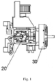
Fig. 1 is a side view of part structure of a power system in an embodiment of the invention; -
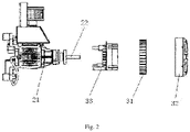
Fig. 2 is the schematic diagram of the breakdown structure ofFig. 1 ; -
Fig.3 is a flowchart of a power system control method in an embodiment of the invention; -
Fig. 4 is a side view of part structure of a UAV in an embodiment of the invention; -
Fig. 5 is the schematic diagram of the breakdown structure ofFig. 4 . - Figure reference signs:
10. Propeller; 20. Engine; 21. Engine body; 22. Engine output shaft; 30. Motor; 31. Stator; 32. Rotor; 33. Stator connector. - In order to clarify the purpose, technical scheme, and advantages of the embodiments of the invention, the technical scheme in the embodiments of the invention will be described clearly and completely below in combination with the figures in the embodiments of the invention. Obviously, the described embodiments are part of the embodiments of the invention, not all of them. The components of the embodiments of the present invention, which are generally described and shown in the figures herein, may be arranged and designed in various types of different configurations. Therefore, the following detailed description of the embodiments of the invention provided in the accompanying drawings is not intended to limit the scope of the invention claimed, but only represents selected embodiments of the invention. Based on the embodiments of the invention, all other embodiments obtained by those skilled in the art without creative work fall within the breadth and scope of the invention.
- It should be noted that similar labels and letters indicate similar items in the following figures. Therefore, once an item is defined in a figure, it does not need to be further defined and explained in subsequent figures.
- In the description of the invention, it should be noted that the orientation or position relationship indicated by the terms "up", "down", "left", "right", "vertical", "horizontal", "inside", "outside" is based on the orientation or position relationship shown in the figures, or the orientation or position relationship that the product of the invention is customarily placed when it is used, only for the convenience of describing the invention and simplifying the description, rather than indicating or implying that the device or element referred to must have a specific orientation, be constructed and operated in a specific orientation, it cannot be understood as a limitation of the invention. In addition, the terms "first", "second", "third" and the like are only used to distinguish descriptions, and cannot be understood as indicating or implying relative importance. In the description of the invention, unless otherwise specified, "multiple" means two or more.
- In the description of the invention, it should also be noted that, unless otherwise expressly specified and limited, the terms "arranged" and "connection" should be understood in a broad sense, for example, it can be fixedly connected, a detachably connected, or integrated. It can be mechanical connection or electrical connection. For those skilled in the art, the specific meaning of the above terms in the invention may be understood in specific circumstances.
- In the description of the invention, unless otherwise clearly specified and limited, the first feature "on" or "under" the second feature may include the direct contact between the first and second features, or the contact between the first and second features that is not direct contact, but through another feature between them. Moreover, the first feature "on", "over", and "above" the second feature may include the first feature directly above and obliquely above the second feature, or only indicates that the horizontal height of the first feature is higher than the second feature. The first feature "under", "below" and "beneath" the second feature, may include the first feature directly below and obliquely below the second feature, or only indicate that the horizontal height of the first feature is smaller than that of the second feature.
- The following describes in detail the embodiments of the invention, examples of which are shown in the figures, in which the same or similar labels throughout represent the same or similar elements or elements with the same or similar functions. The embodiments described below with reference to the figures are exemplary and are only for the purpose of explaining the invention and cannot be understood as limitations of the invention.
- The embodiment aims to provide a power system for outputting power. Upon the specific implementation, the power system can be mounted to the UAV, the ship, or other mechanical equipment that needs to be equipped with the power system to realize the power drive of the corresponding mechanical equipment. Specifically, as shown in
Figs. 1 and2 , the power system includes anengine 20, amotor 30, and a battery. Specifically, theengine 20 includes anengine body 21 and anengine output shaft 22 arranged on theengine body 21, and theengine body 21 is installed on the body of the corresponding mechanical equipment. Themotor 30 includes astator 31, arotor 32 and astator connector 33 for connecting thestator 31 and therotor 32. Upon the specific implementation, thestator connector 33 is arranged on theengine body 21 to realize the stable arrangement of themotor 30. Therotor 32 is coaxially arranged on theengine output shaft 22. Therotor 32 is also used for coaxial connection with the external power receiver, that is, therotor 32, the external power receiver and theengine output shaft 22 are coaxially connected. Themotor 30 in this embodiment may be used as either a generator or an electric motor. When themotor 30 is used as an electric motor, therotor 32 of themotor 30 does positive work on theengine output shaft 22, converting electrical energy into mechanical energy, which can assist theengine 20 for power output. When themotor 30 is used as a generator, theelectronic rotor 32 does negative work on theengine output shaft 22, absorbs the output power of theengine 20, converts mechanical energy into electrical energy, and realizes the power generation operation. The battery is connected to themotor 30, so that when themotor 30 is used as an electric motor, the battery discharges to provide electric energy to themotor 30. When themotor 30 is used as a generator, it can receive the electric energy output by themotor 30 for charging. - Upon the specific implementation, a two-stroke engine may be selected for the
engine 20. The two-stroke engine is an engine that completes a working cycle between two strokes. It has no valve, which can greatly simplify the structure, reduce its own weight, and can be more conveniently and flexibly installed on mechanical equipment, reducing the weight of the whole mechanical equipment, thereby reducing energy consumption. Alternatively, themotor 30 is a permanent magnet synchronous motor or a permanent magnet asynchronous motor. Among them, the permanent magnet synchronous motor matches well with the two-stroke engine, and there is no conversion mechanism, so there is no conversion loss. The permanent magnet synchronous motor and two-stroke engine can work alone or together without clutch. - In order to facilitate the control over the working state of the
engine 20 and themotor 30 of the power system, the power system also includes an engine controller and a motor controller. The engine controller is used to receive the control commands and output the execution signals to theengine 20, so as to control the working state of theengine 20. The motor controller is used to receive the control commands and output the execution signals to themotor 30, so as to control the working state of themotor 30. Further, the power system also includes a control board, which is used to send control commands to the engine controller or motor controller. Of course, the battery can supply power to the control board, engine controller and motor controller to ensure the smooth operation of the control system. - The power system in this embodiment sets the
rotor 32 of themotor 30, the external power receiver and theengine output shaft 22 to be coaxially connected, and themotor 30 can be used as a generator to charge the battery by doing negative work on theengine output shaft 22, or as an electric motor, that is, to receive the power of the battery and do positive work on theengine output shaft 22 to realize power output. - Based on Embodiment 1, this embodiment provides a power system control method for the above power system, which provides the determination process of different operation modes of the power system. Referring to
Fig. 3 , specifically, the power system control method includes the following steps: - S10: Determine whether the
engine 20 could work. If not, the power system enters the pure electric operation mode, in which the battery discharges to provide electric energy to themotor 30, and then themotor 30 provides power. Otherwise, go to the next step; - S20: If the
engine 20 can work, determine whether the output power of theengine 20 meets the needs. If not, the power system enters the power assisted operation mode, in which theengine 20 and themotor 30 provide power at the same time. Otherwise, proceed to the next step; - S30: If the output power of the
engine 20 meets the needs, determine whether theengine 20 works in the low energy consumption range. If not, the power system enters the hybrid operation mode, in which theengine 20 and themotor 30 provide power at the same time, and theengine 20 operates in the low energy consumption range. - In the step S10, determine the operation state of the
engine 20 firstly. Only by ensuring that theengine 20 can work, then assign the work allocation between theengine 20 and themotor 30 reasonably according to the requirement. If theengine 20 cannot work directly, it can only enter the pure electric operation mode, in which the battery provides power, and themotor 30 is used as an electric motor. Specifically, in the step S10, the circumstances under which theengine 20 cannot work normally include but are not limited to the following: the fuel of theengine 20 is running out, the fuel injection nozzle of theengine 20 fails, and theengine 20 loses the rotation signal. Of course, upon the specific implementation, one or more of the above circumstances may occur to theengine 20. As long as any of the above circumstances occurs, it can be determined that theengine 20 cannot work normally. - In the step S20, in the power assisted operation mode, the
engine 20 outputs the maximum power. Upon the specific implementation, if theengine 20 can work normally, theengine 20 is generally used as the main power output. In such case, it is necessary to determine whether the output power of theengine 20 meets the needs in the step S20. If the output power of theengine 20 does not meet the needs and enters the power assisted operation mode at this time, it is necessary to ensure that in this operation mode, theengine 20, which is the main power output, can output maximum power. On the premise that the output power of theengine 20 meets the needs, proceed to the step S30, that is, determine whether theengine 20 works in the low energy consumption range at that time, because although the output power of theengine 20 meets the use requirements, it is not necessarily the optimal output power rate from the perspective of energy consumption. If it is in the non-low energy consumption range, themotor 30 is required to participate in providing power, which is the hybrid operation mode. In the hybrid operation mode, the system will reduce the output power of theengine 20 as much as possible to make it work in the low energy consumption range, while increasing the output power of themotor 30, it can also ensure the normal operation of mechanical equipment. Further, the power system control method also includes a step set after the step S30:
S40: If theengine 20 works in the low energy consumption range, determine whether the remaining power of the battery meets the set value. If not, the power system enters the power generation operation mode, in which the output power part of theengine 20 is received by themotor 30 for charging. - That is, in the step S30, if the
engine 20 has operated in the low energy consumption range, there is no need for themotor 30 to provide additional power. In such case, it can be considered to use theengine 20 to charge the battery, so it is necessary to determine the remaining battery power firstly. When the remaining power of the battery does not meet the set value, on the premise of ensuring the low energy consumption of theengine 20 as much as possible, the output power of theengine 20 can be appropriately increased, so that part of the output power of theengine 20 can be received by themotor 30 for charging operation, so as to ensure that the battery has sufficient power, and also ensure the normal operation of other electrical equipment. At the same time, the battery has enough power storage when entering the power assisted operation mode or hybrid operation mode subsequently. Specifically, in this embodiment, the set value of the remaining power of the battery is set to 80% of the full power. - The power system control method provided in this embodiment makes full use of the structural arrangement of the power system in Embodiment 1, and determines the specific operation mode according to the different operation conditions of the
engine 20, which can achieve power redundancy while ensuring high energy utilization. - Based on Embodiment 1, this embodiment provides a UAV. Referring to
Figs. 4 and5 , the UAV includes the power system described in Embodiment 1. Further, the UAV also includes an UAV body and apropeller 10 arranged on the UAV body. - Specifically, the
engine body 21 is arranged on the UAV body to realize the stable placement of theengine 20 on the UAV, and thepropeller 10 is coaxially arranged on therotor 32 as an external power receiver. Specifically, thepropeller 10 is directly locked on therotor 32 by fasteners. Further, the battery of the power system is not only connected to themotor 30, but also connected to other equipment on the UAV that needs power supply, so as to ensure the normal operation of the whole UAV. The control board of the power system is used to control the whole UAV overall, send corresponding control signals to the engine controller and motor controller according to the ground control signals or the UAV's own needs, and then the engine controller and motor controller control the operation of theengine 20 and themotor 30, respectively. - This embodiment also provides a UAV control method, which can be used in the above UAV. Since the above UAV includes the power system in Embodiment 1, the UAV control method provided in this embodiment naturally also includes the power system control method in
Embodiment 2, that is, the power system control method inEmbodiment 2 is applied to the UAV with this power system, so that the UAV has pure electric operation mode, power assisted operation mode, hybrid operation mode and power generation operation mode. - The conventional UAV built-in generator set generates electric energy by driving the motor with a two-stroke engine. The chemical energy of the fuel needs to be converted into mechanical energy, which is converted into electrical energy through the engine. After the electrical energy finally returns to the battery, it also needs to be converted into mechanical energy to provide power for the UAV. The energy conversion efficiency of the engine itself is only 30%, the conversion efficiency through the generator is 84%, and the conversion efficiency of electric energy into shaft power is 90%. The above conversion efficiency is the ideal average value. During this period, the low conversion efficiency and many conversion times result in extremely low energy utilization rate. Therefore, based on the above defects, the UAV of this embodiment adopts the power system in Embodiment 1, omits the clutch, and connects the
engine 20, themotor 30 and thepropeller 10 coaxially. At the same time, the UAV control system adopts the power system control method inembodiment 2. Therefore, when the above power system is mounted to the UAV, it can make the UAV have high energy utilization and power redundancy, and significantly improve flight safety. Specifically, the step S10 provides the pure electric operation mode of the power system to ensure that when the extreme situation ofengine 20 failure occurs, the UAV can return to the return point or midway forced landing point to ensure the safety of the UAV. In the step S20, for the UAV, a flying vehicle, the output power of theengine 20 is easily affected by altitude. In some operation environments, the maximum power output of theengine 20 is limited and may not meet the use needs of the UAV. In such case, it may enter the power assisted operation mode, in which themotor 30 assists to provide power to ensure that the overall output power of the system meets the requirements, so as to improve the speed of the UAV. For another example, when the UAV needs to fly at full speed or climb, even if the maximum power output of theengine 20 still cannot meet the requirements, it also needs to enter the power assisted operation mode to improve the climbing performance and speed of the UAV. Moreover, on the premise of keeping the level flight power output of the UAV unchanged, the output power of theengine 20 can be increased, and themotor 30 converts this part of the extra power into electrical energy for storage. Therefore, after the UAV is equipped with the above power system, it not only provides the UAV structure with high energy utilization and power redundancy, but also significantly improves flight safety and ensures sufficient endurance and mileage. - Of course, in some other embodiments, the above power system and power system control method may also be used on other mechanical equipment other than UAV to help the corresponding mechanical equipment achieve high energy utilization and power redundancy. For example, the above power system may be applied to the ship, and the propeller of the ship may be used as the external power receiver. The specific embodiment is similar to that of the UAV, which will not be repeated here.
- Based on the UAV and UAV control method provided in Embodiment 3, this embodiment establishes the mathematical model of the power system for UAV, and illustrates several operation modes of UAV through the mathematical model, so as to facilitate the understanding of multiple operation modes and application scenarios of UAV control method.
- Specifically, the mathematical model of the power system of UAV is:

- Where, Pengine is the engine's shaft power; Pmotor is the shaft power of the motor; Ppropeller is the propeller's power; Pbattery-in is the input power of the battery.
- Since the fuel consumption curve of the
engine 20 is known, it is assume that the fuel consumption rate of theengine 20 is 684g/kw.h under the output power is 2200w at 5500rpm and 80% throttle opening; and the fuel consumption rate is 540g/kw.h under the output power is 2000w at 5500rpm and 60% throttle opening; then through the following calculation:

engine 20 can be controlled, and then the increase of the output power of themotor 30 can be controlled, so that theengine 20 may not work in the low energy efficiency range. The specific values of each parameter can be: Pengine = 2000w, Pmotor = 200w, Ppropeller = 2200w; Pbattery-in = 0w. - When the UAV needs to fly at full speed or climb, the output power of the
engine 20 alone may not meet the demand, so the intervention of themotor 30 is required. If the UAV cruises at 140km/h, it needs the shaft power output of 5000w to reach the corresponding thrust, and the maximum engine shaft power is 3000W, the specific values of various parameters can be: Pengine = 3000w, Pmotor = 2000w, Ppropeller = 5000w; Pbattery-in = 0w. - When the UAV is cruising at the speed of 120km/h, only the shaft power output of 1500w is required, and the
engine 20 can meet low energy consumption according to this power output. In order to meet the normal use of the battery of the UAV, theengine 20 will be controlled to output the power of 2000w, and the excess 500w power will be absorbed by themotor 30 and fed back to the battery to charge the battery. The specific values of each parameter can be: Pengine = 2000w, Pmotor = -500w, Ppropeller = 1500w; Pbattery-in = 500w. - Because the pure electric operation mode is only available when the
engine 20 cannot work normally, that is, when theengine 20 fails, the UAV detects that theengine 20 has failed and needs to return immediately. In such case, the return power can only be provided by themotor 30. - Note that the above is only the preferred embodiments of the invention and the technical principle used. Those skilled in the art understands that the invention is not limited to the specific embodiments described here, and it is possible for those skilled in the art to make various obvious changes, readjustments, and substitutions without departing from the protection breadth of the invention. Therefore, although the invention has been described in more detail through the above embodiments, the invention is not limited to the above embodiments, but can also include more equivalent embodiments without departing from the concept of the invention, and the scope of the invention depends upon the scope of the appended claims.
Claims (10)
- A power system for outputting power, which is characterized in that the power system comprises:An engine (20), which comprises an engine body (21) and an engine output shaft (22) arranged on the engine body (21);A motor (30), which comprises a stator (31), a rotor (32) and a stator connector (33) for connecting the stator (31) and the rotor (32); the stator connector (33) is arranged on the engine body (21), andthe rotor (32) is coaxially arranged on the engine output shaft (22); the rotor (32) is used for coaxial connection with an external power receiver;A battery, which is connected to the motor (30), and the battery can discharge to provide electric energy to the motor (30), or receive the electric energy output by the motor (30) for charging.
- The power system according to claim 1, which is characterized in that the engine (20) is a two-stroke engine.
- The power system according to claim 1, which is characterized in that the motor (30) is a permanent magnet synchronous motor.
- The power system according to claim 1, which is characterized in that the power system further comprises:an engine controller for receiving control commands and outputting execution signals to the engine (20);a motor controller for receiving control commands and outputting execution signals to the motor (30).
- A power system control method for the power system according to any one of claims 1-4, which is characterized in that it comprises the following steps:S 10: Determine whether the engine (20) could work. If not, the power system enters the pure electric operation mode, in which the battery discharges to provide electric energy to the motor (30), which then provides power. Otherwise, go to the next step;S20: If the engine (20) can work, determine whether the output power of the engine (20) meets the needs. If not, the power system enters the power assisted operation mode, in which the engine (20) and the motor (30) provide power at the same time. Otherwise, proceed to the next step;S30: If the output power of the engine (20) meets the needs, determine whether the engine (20) works in the low energy consumption range. If not, the power system enters the hybrid operation mode, in which the engine (20) and the motor (30) provide power at the same time, and the engine (20) operates in the low energy consumption range.
- The power system control method according to claim 5, which is characterized in that after the step S30, the following steps are also included:
S40: If the engine (20) works in the low energy consumption range, determine whether the remaining power of the battery meets the set value. If not, the power system enters the power generation operation mode, in which the output power of the engine (20) is partially received by the motor (30) for charging. - The power system control method according to claim 6, which is characterized in that the set value of the remaining power of the battery is 80% of the full power.
- A UAV, which is characterized in that the UAV comprises the power system described in any one of claims 1-4.
- The UAV according to claim 8, which is characterized in that the UAV further comprises a UAV body and a propeller (10) arranged on the UAV body, the engine body (21) is arranged on the UAV body, and the propeller (10) is coaxially arranged on the rotor (32) as the power receiver.
- A UAV control method for the UAV according to claim 8 or 9, which is characterized in that the UAV control method comprises the following steps:S 10: Determine whether the engine (20) could work. If not, the power system enters the pure electric operation mode, in which the battery discharges to provide electric energy to the motor (30), and then the motor (30) provides power. Otherwise, go to the next step;S20: If the engine (20) can work, determine whether the output power of the engine (20) meets the needs. If not, the power system enters the power assisted operation mode; in which the engine (20) and the motor (30) provide power at the same time. Otherwise, proceed to the next step;S30: If the output power of the engine (20) meets the needs, determine whether the engine (20) works in the low energy consumption range. If not, the power system enters the hybrid operation mode, in which the engine (20) and the motor (30) provide power at the same time, and the engine (20) operates in a low energy consumption range.
Applications Claiming Priority (1)
| Application Number | Priority Date | Filing Date | Title |
|---|---|---|---|
| CN202111073126.8A CN113716054B (en) | 2021-09-14 | 2021-09-14 | Control method of power system and control method of unmanned aerial vehicle |
Publications (2)
| Publication Number | Publication Date |
|---|---|
| EP4147976A1 true EP4147976A1 (en) | 2023-03-15 |
| EP4147976B1 EP4147976B1 (en) | 2025-01-22 |
Family
ID=78683520
Family Applications (1)
| Application Number | Title | Priority Date | Filing Date |
|---|---|---|---|
| EP22195058.7A Active EP4147976B1 (en) | 2021-09-14 | 2022-09-12 | Power system, power system control method, uav and uav control method |
Country Status (4)
| Country | Link |
|---|---|
| US (1) | US20230083409A1 (en) |
| EP (1) | EP4147976B1 (en) |
| CN (1) | CN113716054B (en) |
| ES (1) | ES3009682T3 (en) |
Citations (7)
| Publication number | Priority date | Publication date | Assignee | Title |
|---|---|---|---|---|
| US20140010652A1 (en) * | 2012-07-09 | 2014-01-09 | Mcmaster University | Hybrid powertrain system |
| US20180115265A1 (en) * | 2016-10-20 | 2018-04-26 | Top Flight Technologies, Inc. | Hybrid power system characterization |
| EP3403933A1 (en) * | 2017-05-17 | 2018-11-21 | General Electric Company | Hybrid-electric propulsion system for an aircraft |
| US20180354635A1 (en) * | 2017-06-09 | 2018-12-13 | General Electric Company | Propulsion system for an aircraft |
| CN109383784A (en) * | 2018-08-31 | 2019-02-26 | 辽宁同心圆科技有限公司 | Aerial platform with force aid system |
| WO2020079369A1 (en) * | 2018-10-17 | 2020-04-23 | Voltaero | Engine with hybrid powertrain and corresponding control method |
| CN212501058U (en) * | 2020-07-10 | 2021-02-09 | 安徽鸠兹航空智能产业技术研究院有限公司 | High-speed hybrid unmanned aerial vehicle |
Family Cites Families (13)
| Publication number | Priority date | Publication date | Assignee | Title |
|---|---|---|---|---|
| US4171784A (en) * | 1971-03-08 | 1979-10-23 | Karl Eickmann | Combination road and air vehicle having a lowerable chassis |
| EP1046577A3 (en) * | 1999-04-19 | 2001-07-11 | Conway Holdings, Ltd. | Single engined aircraft |
| JP4293182B2 (en) * | 2005-12-16 | 2009-07-08 | トヨタ自動車株式会社 | Hybrid vehicle and control method thereof |
| WO2009042857A2 (en) * | 2007-09-26 | 2009-04-02 | Tesla Motors, Inc. | Operation of a range extended electric vehicle |
| CN100521501C (en) * | 2007-09-30 | 2009-07-29 | 奇瑞汽车股份有限公司 | Torsion management method of mixed power electric motor |
| JP5570782B2 (en) * | 2009-10-16 | 2014-08-13 | 三洋電機株式会社 | POWER SUPPLY DEVICE, VEHICLE EQUIPPED WITH THE SAME, AND CHARGING / DISCHARGE CONTROL METHOD FOR POWER SUPPLY DEVICE |
| CN101890957B (en) * | 2010-05-22 | 2012-12-19 | 张洪延 | Fuel/ electric hybrid multi-mode stepless speed change driving system control method |
| CN106068592B (en) * | 2014-08-08 | 2021-06-11 | 深圳市大疆创新科技有限公司 | Unmanned aerial vehicle battery replacement system and method |
| EP3031732B1 (en) * | 2014-12-12 | 2020-06-10 | Airbus (Sas) | Device and method for cooling at least one autonomous power source of an aircraft |
| US10227066B2 (en) * | 2014-12-26 | 2019-03-12 | Ricoh Company, Ltd. | Operation mode control device, method for controlling operation mode, movable body, output control device, charge discharge control device, and electronic device |
| CN108216646A (en) * | 2018-01-10 | 2018-06-29 | 吉林大学 | A kind of parallel hybrid power aircraft power coupled system and its drive control method |
| CN110040004B (en) * | 2019-04-01 | 2020-10-02 | 一汽-大众汽车有限公司 | Power following control method and system of range-extended pure electric vehicle |
| CN113147431B (en) * | 2021-04-23 | 2024-06-07 | 酷黑科技(北京)有限公司 | Load driving method and extended-range electric driving system |
-
2021
- 2021-09-14 CN CN202111073126.8A patent/CN113716054B/en active Active
-
2022
- 2022-09-12 EP EP22195058.7A patent/EP4147976B1/en active Active
- 2022-09-12 ES ES22195058T patent/ES3009682T3/en active Active
- 2022-09-14 US US17/945,022 patent/US20230083409A1/en not_active Abandoned
Patent Citations (7)
| Publication number | Priority date | Publication date | Assignee | Title |
|---|---|---|---|---|
| US20140010652A1 (en) * | 2012-07-09 | 2014-01-09 | Mcmaster University | Hybrid powertrain system |
| US20180115265A1 (en) * | 2016-10-20 | 2018-04-26 | Top Flight Technologies, Inc. | Hybrid power system characterization |
| EP3403933A1 (en) * | 2017-05-17 | 2018-11-21 | General Electric Company | Hybrid-electric propulsion system for an aircraft |
| US20180354635A1 (en) * | 2017-06-09 | 2018-12-13 | General Electric Company | Propulsion system for an aircraft |
| CN109383784A (en) * | 2018-08-31 | 2019-02-26 | 辽宁同心圆科技有限公司 | Aerial platform with force aid system |
| WO2020079369A1 (en) * | 2018-10-17 | 2020-04-23 | Voltaero | Engine with hybrid powertrain and corresponding control method |
| CN212501058U (en) * | 2020-07-10 | 2021-02-09 | 安徽鸠兹航空智能产业技术研究院有限公司 | High-speed hybrid unmanned aerial vehicle |
Also Published As
| Publication number | Publication date |
|---|---|
| CN113716054A (en) | 2021-11-30 |
| EP4147976B1 (en) | 2025-01-22 |
| CN113716054B (en) | 2023-06-27 |
| US20230083409A1 (en) | 2023-03-16 |
| ES3009682T3 (en) | 2025-03-31 |
Similar Documents
| Publication | Publication Date | Title |
|---|---|---|
| CN111356638B (en) | Power components, power systems and drones | |
| Lee et al. | Active power management system for an unmanned aerial vehicle powered by solar cells, a fuel cell, and batteries | |
| CN109094790B (en) | Power configuration scheme and control method for hybrid power system of helicopter | |
| US12428146B2 (en) | Control system and control method, and aircraft | |
| CN110001975A (en) | Electric unmanned aerial vehicle combined power supply device, method and system | |
| CN109733621A (en) | A kind of hybrid power unmanned plane promoting mode more | |
| CN110481800A (en) | Hybrid power system for multi-rotor aircraft and multi-rotor aircraft | |
| CN117585170A (en) | Distributed multi-oar vertical take-off and landing aircraft hybrid power system and management method | |
| CN114212274A (en) | Helicopter multi-power-source driving system experiment platform | |
| US20240300681A1 (en) | Mobile Engine-Generator Vehicle | |
| CN107264792A (en) | A kind of modular unmanned plane of dynamical system | |
| CN103738503B (en) | A kind of unmanned aerial vehicle onboard generating set | |
| EP4147976A1 (en) | Power system, power system control method, uav and uav control method | |
| CN217805302U (en) | Oil-electricity hybrid power system for aircraft | |
| CN210027898U (en) | A power system and unmanned aerial vehicle | |
| CN110963050B (en) | Multi-energy hybrid propulsion power system for unmanned aerial vehicle | |
| EP4147983A1 (en) | An unmanned aerial vehicle (uav) | |
| US12528357B2 (en) | Estimating system and estimation method and aircraft | |
| CN107963202B (en) | A small long-endurance fixed-wing UAV power controller system and operation method | |
| CN207433818U (en) | A kind of aircraft hybrid power integrated unit | |
| CN111003189A (en) | Power control system and method of hybrid unmanned aerial vehicle | |
| CN116639250A (en) | Parallel type oil-electricity hybrid power system and aircraft | |
| CN214524416U (en) | Many rotor crafts of manned are moved in oil-electricity mixture | |
| CN116986000A (en) | An electric-assisted emergency helicopter power system and transmission method | |
| AU2020104229A4 (en) | Hybrid-power system for multi-rotor-wing aircraft and multi-rotor-wing aircraft |
Legal Events
| Date | Code | Title | Description |
|---|---|---|---|
| PUAI | Public reference made under article 153(3) epc to a published international application that has entered the european phase |
Free format text: ORIGINAL CODE: 0009012 |
|
| STAA | Information on the status of an ep patent application or granted ep patent |
Free format text: STATUS: REQUEST FOR EXAMINATION WAS MADE |
|
| 17P | Request for examination filed |
Effective date: 20221026 |
|
| AK | Designated contracting states |
Kind code of ref document: A1 Designated state(s): AL AT BE BG CH CY CZ DE DK EE ES FI FR GB GR HR HU IE IS IT LI LT LU LV MC MK MT NL NO PL PT RO RS SE SI SK SM TR |
|
| P01 | Opt-out of the competence of the unified patent court (upc) registered |
Effective date: 20230811 |
|
| GRAP | Despatch of communication of intention to grant a patent |
Free format text: ORIGINAL CODE: EPIDOSNIGR1 |
|
| STAA | Information on the status of an ep patent application or granted ep patent |
Free format text: STATUS: GRANT OF PATENT IS INTENDED |
|
| INTG | Intention to grant announced |
Effective date: 20240809 |
|
| GRAS | Grant fee paid |
Free format text: ORIGINAL CODE: EPIDOSNIGR3 |
|
| GRAA | (expected) grant |
Free format text: ORIGINAL CODE: 0009210 |
|
| STAA | Information on the status of an ep patent application or granted ep patent |
Free format text: STATUS: THE PATENT HAS BEEN GRANTED |
|
| AK | Designated contracting states |
Kind code of ref document: B1 Designated state(s): AL AT BE BG CH CY CZ DE DK EE ES FI FR GB GR HR HU IE IS IT LI LT LU LV MC MK MT NL NO PL PT RO RS SE SI SK SM TR |
|
| REG | Reference to a national code |
Ref country code: GB Ref legal event code: FG4D |
|
| REG | Reference to a national code |
Ref country code: CH Ref legal event code: EP |
|
| REG | Reference to a national code |
Ref country code: IE Ref legal event code: FG4D |
|
| REG | Reference to a national code |
Ref country code: DE Ref legal event code: R096 Ref document number: 602022009760 Country of ref document: DE |
|
| REG | Reference to a national code |
Ref country code: ES Ref legal event code: FG2A Ref document number: 3009682 Country of ref document: ES Kind code of ref document: T3 Effective date: 20250331 |
|
| REG | Reference to a national code |
Ref country code: NL Ref legal event code: MP Effective date: 20250122 |
|
| PG25 | Lapsed in a contracting state [announced via postgrant information from national office to epo] |
Ref country code: NL Free format text: LAPSE BECAUSE OF FAILURE TO SUBMIT A TRANSLATION OF THE DESCRIPTION OR TO PAY THE FEE WITHIN THE PRESCRIBED TIME-LIMIT Effective date: 20250122 |
|
| PG25 | Lapsed in a contracting state [announced via postgrant information from national office to epo] |
Ref country code: RS Free format text: LAPSE BECAUSE OF FAILURE TO SUBMIT A TRANSLATION OF THE DESCRIPTION OR TO PAY THE FEE WITHIN THE PRESCRIBED TIME-LIMIT Effective date: 20250422 |
|
| PG25 | Lapsed in a contracting state [announced via postgrant information from national office to epo] |
Ref country code: FI Free format text: LAPSE BECAUSE OF FAILURE TO SUBMIT A TRANSLATION OF THE DESCRIPTION OR TO PAY THE FEE WITHIN THE PRESCRIBED TIME-LIMIT Effective date: 20250122 |
|
| PG25 | Lapsed in a contracting state [announced via postgrant information from national office to epo] |
Ref country code: PL Free format text: LAPSE BECAUSE OF FAILURE TO SUBMIT A TRANSLATION OF THE DESCRIPTION OR TO PAY THE FEE WITHIN THE PRESCRIBED TIME-LIMIT Effective date: 20250122 |
|
| REG | Reference to a national code |
Ref country code: LT Ref legal event code: MG9D |
|
| PG25 | Lapsed in a contracting state [announced via postgrant information from national office to epo] |
Ref country code: IS Free format text: LAPSE BECAUSE OF FAILURE TO SUBMIT A TRANSLATION OF THE DESCRIPTION OR TO PAY THE FEE WITHIN THE PRESCRIBED TIME-LIMIT Effective date: 20250522 Ref country code: NO Free format text: LAPSE BECAUSE OF FAILURE TO SUBMIT A TRANSLATION OF THE DESCRIPTION OR TO PAY THE FEE WITHIN THE PRESCRIBED TIME-LIMIT Effective date: 20250422 |
|
| REG | Reference to a national code |
Ref country code: AT Ref legal event code: MK05 Ref document number: 1761307 Country of ref document: AT Kind code of ref document: T Effective date: 20250122 |
|
| PG25 | Lapsed in a contracting state [announced via postgrant information from national office to epo] |
Ref country code: HR Free format text: LAPSE BECAUSE OF FAILURE TO SUBMIT A TRANSLATION OF THE DESCRIPTION OR TO PAY THE FEE WITHIN THE PRESCRIBED TIME-LIMIT Effective date: 20250122 |
|
| PG25 | Lapsed in a contracting state [announced via postgrant information from national office to epo] |
Ref country code: PT Free format text: LAPSE BECAUSE OF FAILURE TO SUBMIT A TRANSLATION OF THE DESCRIPTION OR TO PAY THE FEE WITHIN THE PRESCRIBED TIME-LIMIT Effective date: 20250522 Ref country code: LV Free format text: LAPSE BECAUSE OF FAILURE TO SUBMIT A TRANSLATION OF THE DESCRIPTION OR TO PAY THE FEE WITHIN THE PRESCRIBED TIME-LIMIT Effective date: 20250122 |
|
| PG25 | Lapsed in a contracting state [announced via postgrant information from national office to epo] |
Ref country code: BG Free format text: LAPSE BECAUSE OF FAILURE TO SUBMIT A TRANSLATION OF THE DESCRIPTION OR TO PAY THE FEE WITHIN THE PRESCRIBED TIME-LIMIT Effective date: 20250122 Ref country code: GR Free format text: LAPSE BECAUSE OF FAILURE TO SUBMIT A TRANSLATION OF THE DESCRIPTION OR TO PAY THE FEE WITHIN THE PRESCRIBED TIME-LIMIT Effective date: 20250423 |
|
| PG25 | Lapsed in a contracting state [announced via postgrant information from national office to epo] |
Ref country code: AT Free format text: LAPSE BECAUSE OF FAILURE TO SUBMIT A TRANSLATION OF THE DESCRIPTION OR TO PAY THE FEE WITHIN THE PRESCRIBED TIME-LIMIT Effective date: 20250122 |
|
| PG25 | Lapsed in a contracting state [announced via postgrant information from national office to epo] |
Ref country code: SE Free format text: LAPSE BECAUSE OF FAILURE TO SUBMIT A TRANSLATION OF THE DESCRIPTION OR TO PAY THE FEE WITHIN THE PRESCRIBED TIME-LIMIT Effective date: 20250122 |
|
| PG25 | Lapsed in a contracting state [announced via postgrant information from national office to epo] |
Ref country code: SM Free format text: LAPSE BECAUSE OF FAILURE TO SUBMIT A TRANSLATION OF THE DESCRIPTION OR TO PAY THE FEE WITHIN THE PRESCRIBED TIME-LIMIT Effective date: 20250122 |
|
| PG25 | Lapsed in a contracting state [announced via postgrant information from national office to epo] |
Ref country code: DK Free format text: LAPSE BECAUSE OF FAILURE TO SUBMIT A TRANSLATION OF THE DESCRIPTION OR TO PAY THE FEE WITHIN THE PRESCRIBED TIME-LIMIT Effective date: 20250122 |
|
| PGFP | Annual fee paid to national office [announced via postgrant information from national office to epo] |
Ref country code: DE Payment date: 20250930 Year of fee payment: 4 |
|
| PGFP | Annual fee paid to national office [announced via postgrant information from national office to epo] |
Ref country code: FR Payment date: 20250924 Year of fee payment: 4 |
|
| PG25 | Lapsed in a contracting state [announced via postgrant information from national office to epo] |
Ref country code: EE Free format text: LAPSE BECAUSE OF FAILURE TO SUBMIT A TRANSLATION OF THE DESCRIPTION OR TO PAY THE FEE WITHIN THE PRESCRIBED TIME-LIMIT Effective date: 20250122 Ref country code: CZ Free format text: LAPSE BECAUSE OF FAILURE TO SUBMIT A TRANSLATION OF THE DESCRIPTION OR TO PAY THE FEE WITHIN THE PRESCRIBED TIME-LIMIT Effective date: 20250122 |
|
| REG | Reference to a national code |
Ref country code: DE Ref legal event code: R097 Ref document number: 602022009760 Country of ref document: DE |
|
| PG25 | Lapsed in a contracting state [announced via postgrant information from national office to epo] |
Ref country code: RO Free format text: LAPSE BECAUSE OF FAILURE TO SUBMIT A TRANSLATION OF THE DESCRIPTION OR TO PAY THE FEE WITHIN THE PRESCRIBED TIME-LIMIT Effective date: 20250122 |
|
| PG25 | Lapsed in a contracting state [announced via postgrant information from national office to epo] |
Ref country code: SK Free format text: LAPSE BECAUSE OF FAILURE TO SUBMIT A TRANSLATION OF THE DESCRIPTION OR TO PAY THE FEE WITHIN THE PRESCRIBED TIME-LIMIT Effective date: 20250122 |
|
| PLBE | No opposition filed within time limit |
Free format text: ORIGINAL CODE: 0009261 |
|
| STAA | Information on the status of an ep patent application or granted ep patent |
Free format text: STATUS: NO OPPOSITION FILED WITHIN TIME LIMIT |
|
| REG | Reference to a national code |
Ref country code: CH Ref legal event code: L10 Free format text: ST27 STATUS EVENT CODE: U-0-0-L10-L00 (AS PROVIDED BY THE NATIONAL OFFICE) Effective date: 20251203 |
|
| 26N | No opposition filed |
Effective date: 20251023 |
|
| PGFP | Annual fee paid to national office [announced via postgrant information from national office to epo] |
Ref country code: IT Payment date: 20250930 Year of fee payment: 4 |
|
| PGFP | Annual fee paid to national office [announced via postgrant information from national office to epo] |
Ref country code: ES Payment date: 20251020 Year of fee payment: 4 |
|
| REG | Reference to a national code |
Ref country code: CH Ref legal event code: H13 Free format text: ST27 STATUS EVENT CODE: U-0-0-H10-H13 (AS PROVIDED BY THE NATIONAL OFFICE) Effective date: 20260425 |