EP4147951A1 - A straddled vehicle with a vehicle exterior part - Google Patents
A straddled vehicle with a vehicle exterior part Download PDFInfo
- Publication number
- EP4147951A1 EP4147951A1 EP22170601.3A EP22170601A EP4147951A1 EP 4147951 A1 EP4147951 A1 EP 4147951A1 EP 22170601 A EP22170601 A EP 22170601A EP 4147951 A1 EP4147951 A1 EP 4147951A1
- Authority
- EP
- European Patent Office
- Prior art keywords
- hole
- reinforcement plate
- mold
- around
- protrusion
- Prior art date
- Legal status (The legal status is an assumption and is not a legal conclusion. Google has not performed a legal analysis and makes no representation as to the accuracy of the status listed.)
- Granted
Links
Images


Classifications
-
- B—PERFORMING OPERATIONS; TRANSPORTING
- B62—LAND VEHICLES FOR TRAVELLING OTHERWISE THAN ON RAILS
- B62J—CYCLE SADDLES OR SEATS; AUXILIARY DEVICES OR ACCESSORIES SPECIALLY ADAPTED TO CYCLES AND NOT OTHERWISE PROVIDED FOR, e.g. ARTICLE CARRIERS OR CYCLE PROTECTORS
- B62J17/00—Weather guards for riders; Fairings or stream-lining parts not otherwise provided for
- B62J17/02—Weather guards for riders; Fairings or stream-lining parts not otherwise provided for shielding only the rider's front
- B62J17/04—Windscreens
-
- B—PERFORMING OPERATIONS; TRANSPORTING
- B29—WORKING OF PLASTICS; WORKING OF SUBSTANCES IN A PLASTIC STATE IN GENERAL
- B29C—SHAPING OR JOINING OF PLASTICS; SHAPING OF MATERIAL IN A PLASTIC STATE, NOT OTHERWISE PROVIDED FOR; AFTER-TREATMENT OF THE SHAPED PRODUCTS, e.g. REPAIRING
- B29C45/00—Injection moulding, i.e. forcing the required volume of moulding material through a nozzle into a closed mould; Apparatus therefor
- B29C45/14—Injection moulding, i.e. forcing the required volume of moulding material through a nozzle into a closed mould; Apparatus therefor incorporating preformed parts or layers, e.g. injection moulding around inserts or for coating articles
- B29C45/14631—Coating reinforcements
-
- B—PERFORMING OPERATIONS; TRANSPORTING
- B29—WORKING OF PLASTICS; WORKING OF SUBSTANCES IN A PLASTIC STATE IN GENERAL
- B29C—SHAPING OR JOINING OF PLASTICS; SHAPING OF MATERIAL IN A PLASTIC STATE, NOT OTHERWISE PROVIDED FOR; AFTER-TREATMENT OF THE SHAPED PRODUCTS, e.g. REPAIRING
- B29C45/00—Injection moulding, i.e. forcing the required volume of moulding material through a nozzle into a closed mould; Apparatus therefor
- B29C45/14—Injection moulding, i.e. forcing the required volume of moulding material through a nozzle into a closed mould; Apparatus therefor incorporating preformed parts or layers, e.g. injection moulding around inserts or for coating articles
- B29C45/14065—Positioning or centering articles in the mould
- B29C2045/14122—Positioning or centering articles in the mould using fixed mould wall projections for centering the insert
Definitions
- the present invention relates to a vehicle exterior part made primarily of resin, a straddled vehicle, and a method for manufacturing a vehicle exterior part.
- Japanese Laid-Open Patent Publication No. 2012-61953 discloses a windscreen that covers an upper front portion of a vehicle body. Such a windscreen is often made of resin. The windscreen is fixed to a metal bracket with bolts and nuts. The windscreen is supported by the vehicle frame with the bracket therebetween. When the vehicle is running, the windscreen is subjected to wind pressure. The part of the windscreen fixed to the bracket needs to be sufficiently rigid. While the windscreen is an example exterior part of a straddled vehicle, but the windscreen is not the only plastic exterior part that needs rigidity.
- a reinforcement plate may be insert-molded into the resin-made body. If a reinforcement plate is provided on one side of the body, the reinforcement plate is likely to peel off the body. Therefore, the reinforcement plate is preferably embedded in the body. That is, both of the front surface and the reverse surface of at least a portion of the reinforcement plate are preferably covered by the body.
- the resin material needs to be supplied to the front surface and the reverse surface of the reinforcement plate in the mold during insert molding. Therefore, when the reinforcement plate is set in the mold, the front surface and the reverse surface of the reinforcement plate need to be separated from the mold surface, and a space needs to be created between the front surface of the reinforcement plate and the mold surface and between the reverse surface of the reinforcement plate and the mold surface. In this case, the front surface or the reverse surface of the reinforcement plate cannot be sufficiently supported by the surface of the mold, and it is not always easy to set the reinforcement plate at an accurate position.
- the position of the reinforcement plate may possibly shift relative to the resin-made body. However, if the position of the reinforcement plate shifts, there will be an error from the design value of the rigidity of the exterior part.
- It is an object of the present invention is to provide a vehicle exterior part made primarily of resin, in which the rigidity thereof is increased by insertion of a reinforcement plate, and in which the position of the reinforcement plate is unlikely to shift.
- a vehicle exterior part disclosed herein includes a resin-made body, and a reinforcement plate that is at least partially embedded in the body.
- the reinforcement plate has a front surface and a reverse surface.
- the body is formed with a first hole and a second hole.
- the reinforcement plate is formed with a first through hole aligned with the first hole and a second through hole aligned with the second hole.
- An inner diameter of the first through hole is less than or equal to an inner diameter of the first hole
- an inner diameter of the second through hole is less than or equal to an inner diameter of the second hole.
- the body includes a first portion that covers a front surface and a reverse surface of the reinforcement plate around the first through hole, and a second portion that covers the front surface and the reverse surface of the reinforcement plate around the second through hole.
- the body is made of resin, it is possible to increase the rigidity because the reinforcement plate is embedded in the body. Since at least the first portion and the second portion of the body cover both of the front surface and the reverse surface of a portion of the reinforcement plate, the reinforcement plate is unlikely to peel off the body.
- the reinforcement plate for example, by providing a mold with a first protrusion and a second protrusion and by fitting the first protrusion into the first through hole and the second protrusion into the second through hole, it is possible to set the reinforcement plate so that the front surface and the reverse surface are spaced apart from the mold.
- the positions of the first through hole and the second through hole are aligned with the first protrusion and the second protrusion, it is possible to accurately position the reinforcement plate relative to the mold. Since the first protrusion and the second protrusion are engaged with the first through hole and the second through hole, the position of the reinforcement plate is unlikely to shift when a resin material is injected into the mold. Therefore, the position of the reinforcement plate is unlikely to shift relative to the body. With the vehicle exterior part described above, there will be little error from the design value of the rigidity.
- the reinforcement plate may include a first exposed portion that is a portion around the first through hole and is not covered by the body, and a second exposed portion that is a portion around the second through hole and is not covered by the body.
- the first portion of the body may cover the front surface and the reverse surface of the reinforcement plate around the first exposed portion.
- the second portion of the body may cover the front surface and the reverse surface of the reinforcement plate around the second exposed portion.
- a fastener such as a bolt can be pressed against the first exposed portion and the second exposed portion of the reinforcement plate.
- the first through hole and the second through hole of the reinforcement plate can suitably be used as holes for fastening the vehicle exterior part to another vehicle part by bolts, or the like. Since the reinforcement plate serves also as a fastening member, it is possible to reduce the number of components and the cost.
- the first hole and/or the second hole may be a through hole.
- the first through hole and/or the second through hole may have a circular shape.
- the reinforcement plate may be formed of metal.
- a portion of the body around the first hole may be depressed in a center line direction of the first through hole.
- a portion of the body around the second hole may be depressed in a center line direction of the second through hole.
- a straddled vehicle disclosed herein includes the vehicle exterior part described above.
- the straddled vehicle may include: a vehicle frame including a head pipe; and a bracket supported on the vehicle frame.
- the vehicle exterior part may be a front cowl that is arranged at least partially forward of the head pipe.
- the front cowl may be fastened to the bracket by a bolt inserted through the first through hole and a bolt inserted through the second through hole.
- a windscreen may be attached to the front cowl.
- a method for manufacturing a vehicle exterior part disclosed herein includes: a setting step of setting a reinforcement plate, which has been formed with a first through hole and a second through hole, in a space between a first mold and a second mold; an injection step of injecting a resin material into the space; a curing step of curing the resin material; and a take-out step of moving the second mold relative to the first mold in a first direction away from the first mold so as to take out the cured resin material with the reinforcement plate embedded therein from the first mold and the second mold.
- the first mold includes a first protrusion and a second protrusion that protrude in the first direction.
- the first protrusion and the second protrusion of the first mold are fitted into the first through hole and the second through hole of the reinforcement plate so as to hold the reinforcement plate by the first protrusion and the second protrusion so that a portion of the reinforcement plate around the first through hole and a portion of the reinforcement plate around the second through hole are separated from a surface of the first mold and a surface of the second mold.
- the reinforcement plate can be set so that the front surface and the reverse surface of a portion around the first through hole are separated from the surface of the first mold and the surface of the second mold, and the front surface and the reverse surface of a portion around the second through hole are separated from the surface of the first mold and the surface of the second mold. Since the positions of the first through hole and the second through hole can be aligned with the positions of the first protrusion and the second protrusion, the reinforcement plate can be accurately positioned relative to the first mold and the second mold. Since the first protrusion and the second protrusion are engaged with the first through hole and the second through hole, the position of the reinforcement plate is unlikely to shift when a resin material is injected. Therefore, the position of the reinforcement plate is unlikely to shift relative to the body. Therefore, the insertion of the reinforcement plate increases the rigidity, and it is possible to realize a vehicle exterior part in which the position of the reinforcement plate is unlikely to shift.
- An ejector pin extending in the first direction may be inserted into the first mold so that the ejector pin can slide in the first direction.
- the resin material may be taken out of the first mold by pushing the resin material in the first direction by the ejector pin.
- the ejector pin With the method described above, it is possible with the ejector pin to easily take out the resin material with the reinforcement plate embedded therein. Since the direction in which the ejector pin extends and the direction in which the first protrusion and the second protrusion of the first mold extend are both the first direction, when moving the second mold in the first direction relative to the first mold, it is possible to smoothly push the resin material by the ejector pin.
- the present invention it is possible to provide a vehicle exterior part made primarily of resin, in which the rigidity thereof is increased by insertion of a reinforcement plate, and in which the position of the reinforcement plate is unlikely to shift.
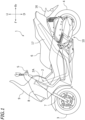
- FIG. 1 is a side view of a motorcycle 1, which is an example of the straddled vehicle.
- the motorcycle 1 according to the present embodiment is a scooter. Note however that there is no particular limitation on the type of the motorcycle 1.
- front, rear, left, right, up and down refer to these directions as seen from a virtual rider (not shown) seated on the seat 6 while the motorcycle 1 is standing upright on a horizontal surface with no rider and no load thereon, unless specified otherwise.
- the motorcycle 1 includes a vehicle frame 2 having a head pipe 2A, a seat 6 supported on the vehicle frame 2, an internal combustion engine 10 pivotably supported on the vehicle frame 2, a handlebar 5 fixed to a steering shaft (not shown) inserted in the head pipe 2A, a front fork 7 fixed to the steering shaft, a front wheel 3 supported on the front fork 7, and a rear wheel 4 driven by the internal combustion engine 10.
- the motorcycle 1 includes a side cover 17, and a rear fender 16 that is arranged at least partially upward of the rear wheel 4.
- the motorcycle 1 includes a front cowl 8 that is arranged at least partially forward of the head pipe 2A, and a windscreen 9 attached to the front cowl 8.
- the front cowl 8 is an example of the vehicle exterior part made primarily of resin.
- FIG. 1 is a perspective view of a bracket 12 is fixed to the vehicle frame 2.
- FIG. 2 is a perspective view of the bracket 12.
- FIG. 3 is a perspective view of the bracket 12, the front cowl 8 and the windscreen 9. The front cowl 8 and the windscreen 9 are supported on the bracket 12.
- FIG. 4 is a front view of the front cowl 8.
- FIG. 5 is a back view of the front cowl 8.
- the front cowl 8 includes a resin-made body 20, and left and right reinforcement plates 30 that are at least partially embedded in the body 20.
- the material of the body 20 a resin of a relatively low rigidity may be used.
- the material of the body 20 is PP (polypropylene).
- the material of the body 20 may be nylon.
- Various resin materials known in the art may be used as the material of the body 20.
- the main body 20 is formed with left and right grooves 25.
- the groove 25 is depressed from the front side toward the reverse side. In other words, the groove 25 is depressed toward the rear side.
- the groove 25 extends downward. While the groove 25 may extend straight as viewed from the front side, it is formed here in a partially bent shape. Note however that there is no particular limitation on the shape of the groove 25.
- each groove 25 Formed inside each groove 25 are a first hole 21, a second hole 22, a third hole 23 and a fourth hole 24.
- first hole 21, the second hole 22, the third hole 23 and the fourth hole 24 may be non-through holes, they are through holes in the present embodiment.
- shape of the first hole 21, the second hole 22, the third hole 23 and the fourth hole 24 is a circular shape in the present embodiment.
- the body 20 is formed with left and right fastening holes 26 and left and right fastening holes 27.
- the fastening holes 26 is formed at least partially upward relative to the groove 25.
- the fastening hole 27 is formed at least partially downward relative to the groove 25.
- screws 41 for fastening the windscreen 9 to the front cowl 8 are inserted through the fastening holes 26 and the fastening holes 27.
- the reinforcement plate 30 is formed of a material whose rigidity is higher than the body 20.
- the material of the reinforcement plate 30 is metal.
- the material of the reinforcement plate 30 may be iron, stainless or aluminum. There is no particular limitation on the type of metal.
- the material of the reinforcement plate 30 is not limited to metal.
- the material of the reinforcement plate 30 may be a resin whose rigidity is higher than the material of the body 20.
- FIG. 6 is a front view of the left reinforcement plate 30.
- the right reinforcement plate 30 has a shape that is in left-right symmetry with the left reinforcement plate 30.
- the reinforcement plate 30 may be formed in a flat plate shape, it may be formed in a bent plate shape in the present embodiment.
- the reinforcement plate 30 is formed in a relatively elongated shape.
- the ratio L30/W30 of the length L30 with respect to the width W30 of the reinforcement plate 30 is relatively large. Although there is no particular limitation on the value of the ratio L30/W30, it may be 4 or more, 5 or more, or 6 or more, for example.
- the reinforcement plate 30 is formed with a first through hole 31, a second through hole 32, a third through hole 33 and a fourth through hole 34.
- the shape of the first through hole 31, the second through hole 32, the third through hole 33 and the fourth through hole 34 is a circular shape in the present embodiment.
- the inner diameters of the first through hole 31, the second through hole 32, the third through hole 33 and the fourth through hole 34 may be different from each other, they are here equal to each other.
- the reinforcement plate 30 is formed with other through holes 35 and 36.
- the formation of the other through holes 35 and 36 reduces the weight of the reinforcement plate 30. Note however that one or both of the through hole 35 and the through hole 36 may be optional.
- the reinforcement plate 30 may be formed with other through holes other than the through holes 35 and 36.
- the reinforcement plate 30 is arranged downward of the fastening hole 26 and upward of the fastening hole 27.
- the reinforcement plate 30 is arranged partially on the straight line L that connects between the center of the fastening hole 26 and the center of the fastening hole 27.
- FIG. 7 is a cross-sectional view taken along line VII-VII of FIG. 3 .
- the first through hole 31 of the reinforcement plate 30 is aligned with the first hole 21 of the body 20.
- the second through hole 32 is aligned with the second hole 22, the third through hole 33 to the third hole 23, and the fourth through hole 34 to the fourth hole 24 (see FIG. 4 ).
- the portion of the reinforcement plate 30 around the first through hole 31 is embedded in the body 20.
- the body 20 includes a first portion 51 that covers a front surface 30A and a reverse surface 30B of the reinforcement plate 30 around the first through hole 31.
- the first portion 51 may cover only a portion of the circumference of the first through hole 31 of the reinforcement plate 30, the first portion 51 herein covers the entire circumference of the first through hole 31.
- the body 20 includes a second portion 52, a third portion 53 and a fourth portion 54 that cover the front surface 30A and the reverse surface 30B of the reinforcement plate 30 around the second through hole 32, the third through hole 33 and the fourth through hole 34, respectively (see FIG. 4 ).
- the second portion 52, the third portion 53 and the fourth portion 54 cover the entire circumferences of the second through hole 32, the third through hole 33 and the fourth through hole 34, respectively. Note however that the second portion 52 may only cover a portion of the circumference of the second through hole 32, the third portion 53 may only cover a portion of the circumference of the third through hole 33, and the fourth portion 54 may only cover a portion of the circumference of the fourth through hole 34.
- the inner diameter d31 of the first through hole 31 is less than or equal to the inner diameter d21 of the first hole 21.
- the inner diameter of the second through hole 32 is less than or equal to the inner diameter of the second hole 22
- the inner diameter of the third through hole 33 is less than or equal to the inner diameter of the third hole 23
- the inner diameter of the fourth through hole 34 is less than or equal to the inner diameter of the fourth hole 24.
- the inner diameter d31 of the first through hole 31 is smaller than the inner diameter d21 of the first hole 21. D31 ⁇ d21.
- the inner diameter of the second through hole 32 is smaller than the inner diameter of the second hole 22
- the inner diameter of the third through hole 33 is smaller than the inner diameter of the third hole 23
- the inner diameter of the fourth through hole 34 is smaller than the inner diameter of the fourth hole 24.
- the reinforcement plate 30 includes a first exposed portion 31A that is a portion around the first through hole 31 and is not covered by the body 20.
- the first portion 51 of the body 20 covers the front surface 30A and the reverse surface 30B of the reinforcement plate 30 around the first exposed portion 31A.
- the reinforcement plate 30 includes a second exposed portion 32A that is a portion around the second through hole 32 and is not covered by the body 20 (see FIG. 4 ).
- the reinforcement plate 30 includes a third exposed portion 33A that is a portion around the third through hole 33 and is not covered by the body 20.
- the reinforcement plate 30 includes a fourth exposed portion 34A that is a portion around the fourth through hole 34 and is not covered by the body 20.
- the second portion 52 of the body covers the front surface 30A and the reverse surface 30B of the reinforcement plate 30 around the second exposed portion 32A.
- the third portion 53 of the body covers the front surface 30A and the reverse surface 30B of the reinforcement plate 30 around the third exposed portion 33A.
- the fourth portion 54 of the body covers the front surface 30A and the reverse surface 30B of the reinforcement plate 30 around the fourth exposed portion 34A.
- the first hole 21, the second hole 22, the third hole 23 and the fourth hole 24 of the body 20 are formed inside the groove 25.
- a portion of the body 20 around the first hole 21 is depressed downward.
- a portion of the body 20 around the first hole 21 is depressed in the center line direction of the first through hole 31.
- a portion of the body 20 around the second hole 22 is depressed in the center line direction of the second through hole 32.
- a portion of the body 20 around the third hole 23 is depressed in the center line direction of the third through hole 33.
- a portion of the body 20 around the fourth hole 24 is depressed in the center line direction of the fourth through hole 34.
- the front cowl 8 is fastened to the bracket 12 by bolts 42.
- the bracket 12 includes left and right first bosses 13 and left and right second bosses 14.
- the front cowl 8 is fastened to the first bosses 13 and the second bosses 14 by the bolts 42.
- the front cowl 8 is supported on the vehicle frame 2 with the bracket 12 therebetween.
- the front cowl 8 can take two positions, i.e., the first position and the second position, with respect to the bracket 12.
- the bolt 42 When positioning the front cowl 8 in the first position, the bolt 42 is fastened to the first through hole 31 and the first boss 13 (see FIG. 7 ), and the bolt 42 is fastened to the third through hole 33 and the second boss 14.
- the front cowl 8 is attached to the bracket 12 at a relatively low position (see FIG. 3 ).
- the bolt 42 is fastened to the second through hole 32 and the first boss 13, and the bolt 42 is fastened to the fourth through hole 34 and the second boss 14.
- the front cowl 8 is attached to the bracket 12 at a relatively high position.
- first through hole 31, the second through hole 32, the third through hole 33 and the fourth through hole 34 of the reinforcement plate 30 are used as fastening holes for fastening the front cowl 8 to the bracket 12.
- FIG. 8 is a cross-sectional view taken along line VIII-VIII of FIG. 3 .
- a well nut 44 is inserted into the fastening hole 26 of the front cowl 8.
- the screw 41 is fastened to the well nut 44.
- the windscreen 9 is fastened to the screw 41 and the well nut 44.
- the windscreen 9 is attached to the front cowl 8 by the screw 41 and the well nut 44.
- another well nut 44 is inserted into the fastening hole 27 of the front cowl 8, and another screw 41 is fastened to the other well nut 44.
- the windscreen 9 is attached to the front cowl 8 also by the other screw 41 and the other well nut 44 (see FIG. 3 ).
- the front cowl 8 is manufactured by insert molding.
- the front cowl 8 is manufactured, for example, by injecting a heated molten resin material around the reinforcement plate 30 set in an injection mold, and curing the resin material.
- FIG. 9 is a flow chart showing an example of a method for manufacturing the front cowl 8.
- FIG. 10 is a partial cross-sectional view of an example of a mold 60.
- the mold 60 includes a first mold 61 and a second mold 62.
- the direction of the arrow F1 of FIG. 10 will be referred to as the first direction, and the direction of the arrow F2 as the second direction.
- the second direction F2 is the opposite direction to the first direction F1 .
- the first mold 61 includes a first protrusion 61A and a second protrusion 61B protruding in the first direction F1 .
- the first mold 61 includes a third protrusion and a fourth protrusion protruding in the first direction F1 .
- Ejector pins 65 are inserted into the first mold 61.
- the ejector pins 65 extend in the first direction F1 .
- the ejector pins 65 can slide against the first mold 61 in the first direction F1 .
- the ejector pins 65 are inserted into the first mold 61 so that the ejector pins 65 can slide in the first direction F1 .
- a setting step of setting the reinforcement plate 30 in a space 63 between the first mold 61 and the second mold 62 is performed (step S 1).
- the first protrusion 61A of the first mold 61 is fitted into the first through hole 31 of the reinforcement plate 30, the second protrusion 61B of the first mold 61 is fitted into the second through hole 32 of the reinforcement plate 30.
- the reinforcement plate 30 is held by the first protrusion 61A and the second protrusion 61B.
- the third protrusion of the first mold 61 is fitted into the third through hole 33 of the reinforcement plate 30, and the fourth protrusion of the first mold 61 is fitted into the fourth through hole 34 of the reinforcement plate 30.
- the reinforcement plate 30 is held also by the third protrusion and the fourth protrusion.
- the front surface 30A and the reverse surface 30B of at least a portion of the reinforcement plate 30 are spaced apart from a surface 61S of the first mold 61 and a surface 62S of the second mold 62. Therefore, in the injection step to be described below, it is possible to supply a resin material to both of the front surface 30A and the reverse surface 30B of the reinforcement plate 30.
- the position of the first through hole 31 is aligned with the position of the first protrusion 61A, and the position of the second through hole 32 is aligned with the position of the second protrusion 61B. Therefore, it is possible to place the reinforcement plate 30 at an accurate position relative to the first mold 61 and the second mold 62.
- a resin material is injected into the space 63 between the first mold 61 and the second mold 62 (step S2). That is, the injection step is performed.
- the first protrusion 61A and the second protrusion 61B of the first mold 61 are engaged with the first through hole 31 and the second through hole 32 of the reinforcement plate 30, respectively. Therefore, when a resin material is injected, the position of the reinforcement plate 30 is unlikely to shift. It is possible to prevent the position of the reinforcement plate 30 in the mold 60 from shifting.
- the reinforcement plate 30 can rotate about the first protrusion 61A.
- through holes other than the first through hole 31 e.g., the second through hole 32
- the first mold 61 includes protrusions other than the first protrusion 61A (e.g., the second protrusion 61B).
- the reinforcement plate 30 cannot rotate about the first protrusion 61A. Therefore, it is possible to prevent the reinforcement plate 30 from rotating when a resin material is injected. This also prevents the position of the reinforcement plate 30 in the mold 60 from shifting.
- step S3 the mold 60 is cooled to cure the resin material. That is, the curing step is performed.
- the second mold 62 is moved in the first direction F1, which is the direction away from the first mold 61.
- the cured resin material with the reinforcement plate 30 embedded therein i.e., the front cowl 8
- the take-out step is performed.
- the resin material can desirably be pushed in the first direction F1 by the ejector pins 65 (see FIG. 11 ).
- the second mold 62 can be moved in the first direction F1 relative to the first mold 61.
- the first mold 61 may be moved in the second direction F2.
- the second mold 62 may be moved in the first direction F1 as well as moving the first mold 61 in the second direction F2.
- the direction in which the ejector pins 65 extend and the direction in which the first protrusion 61A and the second protrusion 61B of the first mold 61 extend are both the first direction F1 .
- the front cowl 8 can be manufactured as described above.
- the reinforcement plate 30 is embedded in the body 20, and it is therefore possible to increase the rigidity. Since at least the first portion 51 and the second portion 52 of the body 20 cover both the front surface 30A and the reverse surface 30B of at least a portion of the reinforcement plate 30, the reinforcement plate 30 is unlikely to peel off the body 20.
- the reinforcement plate 30 can be set in the mold 60 so that the front surface 30A and the reverse surface 30B are spaced apart from the surface 61S of the first mold 61 and the surface 62S of the second mold 62. Since the positions of the first through hole 31 and the second through hole 32 are aligned with the positions of the first protrusion 61A and the second protrusion 61B, respectively, it is possible to accurately position the reinforcement plate 30 with the mold 60.
- the reinforcement plate 30 Since the first protrusion 61A and the second protrusion 61B engage with the first through hole 31 and the second through hole 32, when a resin material is injected into the mold 60, the position of the reinforcement plate 30 is unlikely to shift. Therefore, the position of the reinforcement plate 30 is unlikely to shift relative to the body 20. Particularly, the reinforcement plate 30 according to the present embodiment has a relatively elongated shape, but even with the reinforcement plate 30 of such a shape, the position thereof is unlikely to occur. With the front cowl 8 according to the present embodiment, since the position of the reinforcement plate 30 is unlikely to shift, and there will be little error from the design value of the rigidity.
- the reinforcement plate 30 includes the first exposed portion 31A around the first through hole 31, the second exposed portion 32A around the second through hole 32, the third exposed portion 33A around the third through hole 33, and the fourth exposed portion 34A around the fourth through hole 34.
- the head of the bolt 42 and the boss 13 can be pressed against the first exposed portion 31A, the second exposed portion 32A, the third exposed portion 33A and the fourth exposed portion 34A (see FIG. 7 ).
- the first through hole 31, the second through hole 32, the third through hole 33 and the fourth through hole 34 can be used desirably not only as holes for preventing the position of the reinforcement plate 30 from shifting during the manufacture, but also as holes for fastening the front cowl 8 to the bracket 12 by the bolts 42. Since the reinforcement plate 30 serves not only as a member for increasing the rigidity, but also as a fastening member, it is possible to reduce the number of components and the cost.
- the first hole 21, the second hole 22, the third hole 23 and the fourth hole 24 of the body 20 are formed inside the groove 25.
- a portion around the first hole 21 is depressed in the center line direction of the first through hole 31 (see FIG. 7 ).
- a portion around the second hole 22 is depressed in the center line direction of the second through hole 32.
- a portion around the third hole 23 is depressed in the center line direction of the third through hole 33.
- a portion around the fourth hole 24 is depressed in the center line direction of the fourth through hole 34.
- the reinforcement plate 30 includes the first exposed portion 31A around the first through hole 31.
- the first through hole 31 is used as a hole for fastening the front cowl 8 to the bracket 12 by the bolt 42.
- the first through hole 31 does not need to be used as a hole for fastening.
- the reinforcement plate 30 does not need to include the first exposed portion 31A around the first through hole 31.
- the first hole 21 of the body 20 may be a hole having a constant inner diameter, or may be shaped so that the inner diameter decreases gradually from one of the front side and the reverse side to the other.
- the inner diameter d21 of the first hole 21 refers to the larger one of the inner diameter at the opening on the front side and the inner diameter at the opening on the reverse side.
- the inner diameter d31 of the first through hole 31 is less than or equal to the inner diameter d21 of the first hole 21.
- the first protrusion 61A of the first mold 61 can be fitted into the first through hole 31 during the manufacture, thereby allowing the reinforcement plate 30 to be set with the front surface 30A and the reverse surface 30B spaced apart from the surface 61S of the first mold 61 and the surface 62S of the second mold 62.
- a resin material is injected into the space 63 in the mold 60, it is possible to prevent the position of the reinforcement plate 30 from shifting. Therefore, since the position of the reinforcement plate 30 is unlikely to shift, there will be little error from the design value of the rigidity of the front cowl 8. Note that this similarly applies to the second through hole 32, the third through hole 33 and the fourth through hole 34.
- One or two or more of the second exposed portion 32A, the third exposed portion 33A and the fourth exposed portion 34A may be optional.
- the first hole 21 of the body 20 is a through hole.
- the first hole 21 may be a non-through hole as shown in FIG. 14 . That is, the first hole 21 may be a depression.
- the inner diameter d31 of the first through hole 31 is less than or equal to the inner diameter d21 of the first hole 21.
- the first protrusion 61A of the first mold 61 can be fitted into the first through hole 31 during the manufacture, thereby allowing the reinforcement plate 30 to be set with the front surface 30A and the reverse surface 30B spaced apart from the surface 61S of the first mold 61 and the surface 62S of the second mold 62.
- a resin material is injected into the space 63 in the mold 60, it is possible to prevent the position of the reinforcement plate 30 from shifting. Therefore, since the position of the reinforcement plate 30 is unlikely to shift, there will be little error from the design value of the rigidity of the front cowl 8. Note that this similarly applies to the second hole 22, the third hole 23 and the fourth hole 24.
- One or two or more of the second hole 22, the third hole 23 and the fourth hole 24 may be a non-through hole.
- the vehicle exterior part made primarily of resin is not limited to the front cowl 8.
- the vehicle exterior part made primarily of resin may be the rear fender 16 (see FIG. 1 ) or the side cover 17.
- the present invention is applicable to any vehicle exterior part of a straddled vehicle.
- a straddled vehicle refers to a vehicle that is straddled by the rider.
- the straddled vehicle is not limited to the motorcycle 1.
- the straddled vehicle may be an auto tricycle, an ATV (All Terrain Vehicle), or a snowmobile, for example.
Landscapes
- Engineering & Computer Science (AREA)
- Mechanical Engineering (AREA)
- Manufacturing & Machinery (AREA)
- Body Structure For Vehicles (AREA)
- Moulds For Moulding Plastics Or The Like (AREA)
Abstract
Description
- The present invention relates to a vehicle exterior part made primarily of resin, a straddled vehicle, and a method for manufacturing a vehicle exterior part.
- Conventionally, resin-made exterior parts are often used in straddled vehicles. For example,
Japanese Laid-Open Patent Publication No. 2012-61953 - In order to increase the rigidity of a resin-made exterior part, a reinforcement plate may be insert-molded into the resin-made body. If a reinforcement plate is provided on one side of the body, the reinforcement plate is likely to peel off the body. Therefore, the reinforcement plate is preferably embedded in the body. That is, both of the front surface and the reverse surface of at least a portion of the reinforcement plate are preferably covered by the body.
- However, when both of the front surface and the reverse surface of the reinforcement plate are covered by the body, the resin material needs to be supplied to the front surface and the reverse surface of the reinforcement plate in the mold during insert molding. Therefore, when the reinforcement plate is set in the mold, the front surface and the reverse surface of the reinforcement plate need to be separated from the mold surface, and a space needs to be created between the front surface of the reinforcement plate and the mold surface and between the reverse surface of the reinforcement plate and the mold surface. In this case, the front surface or the reverse surface of the reinforcement plate cannot be sufficiently supported by the surface of the mold, and it is not always easy to set the reinforcement plate at an accurate position. The position of the reinforcement plate may possibly shift relative to the resin-made body. However, if the position of the reinforcement plate shifts, there will be an error from the design value of the rigidity of the exterior part.
- It is an object of the present invention is to provide a vehicle exterior part made primarily of resin, in which the rigidity thereof is increased by insertion of a reinforcement plate, and in which the position of the reinforcement plate is unlikely to shift.
- A vehicle exterior part disclosed herein includes a resin-made body, and a reinforcement plate that is at least partially embedded in the body. The reinforcement plate has a front surface and a reverse surface. The body is formed with a first hole and a second hole. The reinforcement plate is formed with a first through hole aligned with the first hole and a second through hole aligned with the second hole. An inner diameter of the first through hole is less than or equal to an inner diameter of the first hole, and an inner diameter of the second through hole is less than or equal to an inner diameter of the second hole. The body includes a first portion that covers a front surface and a reverse surface of the reinforcement plate around the first through hole, and a second portion that covers the front surface and the reverse surface of the reinforcement plate around the second through hole.
- With the vehicle exterior part described above, although the body is made of resin, it is possible to increase the rigidity because the reinforcement plate is embedded in the body. Since at least the first portion and the second portion of the body cover both of the front surface and the reverse surface of a portion of the reinforcement plate, the reinforcement plate is unlikely to peel off the body. With the vehicle exterior part described above, for example, by providing a mold with a first protrusion and a second protrusion and by fitting the first protrusion into the first through hole and the second protrusion into the second through hole, it is possible to set the reinforcement plate so that the front surface and the reverse surface are spaced apart from the mold. Since the positions of the first through hole and the second through hole are aligned with the first protrusion and the second protrusion, it is possible to accurately position the reinforcement plate relative to the mold. Since the first protrusion and the second protrusion are engaged with the first through hole and the second through hole, the position of the reinforcement plate is unlikely to shift when a resin material is injected into the mold. Therefore, the position of the reinforcement plate is unlikely to shift relative to the body. With the vehicle exterior part described above, there will be little error from the design value of the rigidity.
- An inner diameter of the first through hole may be smaller than an inner diameter of the first hole. An inner diameter of the second through hole may be smaller than an inner diameter of the second hole. The reinforcement plate may include a first exposed portion that is a portion around the first through hole and is not covered by the body, and a second exposed portion that is a portion around the second through hole and is not covered by the body. The first portion of the body may cover the front surface and the reverse surface of the reinforcement plate around the first exposed portion. The second portion of the body may cover the front surface and the reverse surface of the reinforcement plate around the second exposed portion.
- Thus, a fastener such as a bolt can be pressed against the first exposed portion and the second exposed portion of the reinforcement plate. The first through hole and the second through hole of the reinforcement plate can suitably be used as holes for fastening the vehicle exterior part to another vehicle part by bolts, or the like. Since the reinforcement plate serves also as a fastening member, it is possible to reduce the number of components and the cost.
- The first hole and/or the second hole may be a through hole.
- The first through hole and/or the second through hole may have a circular shape.
- The reinforcement plate may be formed of metal.
- A portion of the body around the first hole may be depressed in a center line direction of the first through hole. A portion of the body around the second hole may be depressed in a center line direction of the second through hole.
- Thus, it is possible to increase the rigidity of the portion of the body around the first hole and/or the portion of the body around the second hole.
- A straddled vehicle disclosed herein includes the vehicle exterior part described above.
- The straddled vehicle may include: a vehicle frame including a head pipe; and a bracket supported on the vehicle frame. The vehicle exterior part may be a front cowl that is arranged at least partially forward of the head pipe. The front cowl may be fastened to the bracket by a bolt inserted through the first through hole and a bolt inserted through the second through hole. A windscreen may be attached to the front cowl.
- A method for manufacturing a vehicle exterior part disclosed herein includes: a setting step of setting a reinforcement plate, which has been formed with a first through hole and a second through hole, in a space between a first mold and a second mold; an injection step of injecting a resin material into the space; a curing step of curing the resin material; and a take-out step of moving the second mold relative to the first mold in a first direction away from the first mold so as to take out the cured resin material with the reinforcement plate embedded therein from the first mold and the second mold. The first mold includes a first protrusion and a second protrusion that protrude in the first direction. In the setting step, the first protrusion and the second protrusion of the first mold are fitted into the first through hole and the second through hole of the reinforcement plate so as to hold the reinforcement plate by the first protrusion and the second protrusion so that a portion of the reinforcement plate around the first through hole and a portion of the reinforcement plate around the second through hole are separated from a surface of the first mold and a surface of the second mold.
- With the manufacturing method described above, the reinforcement plate can be set so that the front surface and the reverse surface of a portion around the first through hole are separated from the surface of the first mold and the surface of the second mold, and the front surface and the reverse surface of a portion around the second through hole are separated from the surface of the first mold and the surface of the second mold. Since the positions of the first through hole and the second through hole can be aligned with the positions of the first protrusion and the second protrusion, the reinforcement plate can be accurately positioned relative to the first mold and the second mold. Since the first protrusion and the second protrusion are engaged with the first through hole and the second through hole, the position of the reinforcement plate is unlikely to shift when a resin material is injected. Therefore, the position of the reinforcement plate is unlikely to shift relative to the body. Therefore, the insertion of the reinforcement plate increases the rigidity, and it is possible to realize a vehicle exterior part in which the position of the reinforcement plate is unlikely to shift.
- An ejector pin extending in the first direction may be inserted into the first mold so that the ejector pin can slide in the first direction. In the take-out step, the resin material may be taken out of the first mold by pushing the resin material in the first direction by the ejector pin.
- With the method described above, it is possible with the ejector pin to easily take out the resin material with the reinforcement plate embedded therein. Since the direction in which the ejector pin extends and the direction in which the first protrusion and the second protrusion of the first mold extend are both the first direction, when moving the second mold in the first direction relative to the first mold, it is possible to smoothly push the resin material by the ejector pin.
- According to the present invention, it is possible to provide a vehicle exterior part made primarily of resin, in which the rigidity thereof is increased by insertion of a reinforcement plate, and in which the position of the reinforcement plate is unlikely to shift.
-
-
FIG. 1 is a side view of a motorcycle according to an embodiment. -
FIG. 2 is a perspective view of a bracket. -
FIG. 3 is a perspective view of a bracket, a front cowl and a windscreen. -
FIG. 4 is a front view of a front cowl. -
FIG. 5 is a back view of a front cowl. -
FIG. 6 is a front view of a reinforcement plate. -
FIG. 7 is a cross-sectional view taken along line VII-VII ofFIG. 3 . -
FIG. 8 is a cross-sectional view taken along line VIII-VIII ofFIG. 3 . -
FIG. 9 is a flow chart showing an example of a method for manufacturing a front cowl. -
FIG. 10 is a partial cross-sectional view of a mold in which a reinforcement plate is set. -
FIG. 11 is a partial cross-sectional view of a mold and a front cowl, schematically showing a state where the mold is opened. -
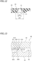
FIG. 12 is a partial cross-sectional view of a front cowl according to an alternative embodiment. -
FIG. 13 is a partial cross-sectional view of a mold in which a reinforcement plate is set, illustrating an alternative embodiment. -
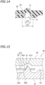
FIG. 14 is a partial cross-sectional view of a front cowl according to an alternative embodiment. -
FIG. 15 is a partial cross-sectional view of a mold in which a reinforcement plate is set, illustrating an alternative embodiment. - An embodiment will now be described with reference to the drawings.
FIG. 1 is a side view of amotorcycle 1, which is an example of the straddled vehicle. Themotorcycle 1 according to the present embodiment is a scooter. Note however that there is no particular limitation on the type of themotorcycle 1. - The terms front, rear, left, right, up and down, as used in the description below, refer to these directions as seen from a virtual rider (not shown) seated on the
seat 6 while themotorcycle 1 is standing upright on a horizontal surface with no rider and no load thereon, unless specified otherwise. The designations F, Rr, L, R, U and D, as used in the figures, refer to front, rear, left, right, up and down, respectively. - The
motorcycle 1 includes a vehicle frame 2 having ahead pipe 2A, aseat 6 supported on the vehicle frame 2, aninternal combustion engine 10 pivotably supported on the vehicle frame 2, ahandlebar 5 fixed to a steering shaft (not shown) inserted in thehead pipe 2A, a front fork 7 fixed to the steering shaft, afront wheel 3 supported on the front fork 7, and arear wheel 4 driven by theinternal combustion engine 10. Themotorcycle 1 includes aside cover 17, and arear fender 16 that is arranged at least partially upward of therear wheel 4. - The
motorcycle 1 includes afront cowl 8 that is arranged at least partially forward of thehead pipe 2A, and awindscreen 9 attached to thefront cowl 8. Thefront cowl 8 is an example of the vehicle exterior part made primarily of resin. - Although not shown in
FIG. 1 , abracket 12 is fixed to the vehicle frame 2.FIG. 2 is a perspective view of thebracket 12.FIG. 3 is a perspective view of thebracket 12, thefront cowl 8 and thewindscreen 9. Thefront cowl 8 and thewindscreen 9 are supported on thebracket 12. -
FIG. 4 is a front view of thefront cowl 8.FIG. 5 is a back view of thefront cowl 8. Thefront cowl 8 includes a resin-madebody 20, and left andright reinforcement plates 30 that are at least partially embedded in thebody 20. - Although there is no particular limitation on the material of the
body 20, a resin of a relatively low rigidity may be used. Here, the material of thebody 20 is PP (polypropylene). The material of thebody 20 may be nylon. Various resin materials known in the art may be used as the material of thebody 20. Themain body 20 is formed with left andright grooves 25. Thegroove 25 is depressed from the front side toward the reverse side. In other words, thegroove 25 is depressed toward the rear side. Thegroove 25 extends downward. While thegroove 25 may extend straight as viewed from the front side, it is formed here in a partially bent shape. Note however that there is no particular limitation on the shape of thegroove 25. - Formed inside each
groove 25 are afirst hole 21, asecond hole 22, athird hole 23 and afourth hole 24. Although thefirst hole 21, thesecond hole 22, thethird hole 23 and thefourth hole 24 may be non-through holes, they are through holes in the present embodiment. Although there is no particular limitation on the shape of thefirst hole 21, thesecond hole 22, thethird hole 23 and thefourth hole 24, the shape is a circular shape in the present embodiment. - The
body 20 is formed with left and right fastening holes 26 and left and right fastening holes 27. The fastening holes26 is formed at least partially upward relative to thegroove 25. Thefastening hole 27 is formed at least partially downward relative to thegroove 25. As shown inFIG. 3 , screws 41 for fastening thewindscreen 9 to thefront cowl 8 are inserted through the fastening holes 26 and the fastening holes 27. - The
reinforcement plate 30 is formed of a material whose rigidity is higher than thebody 20. In the present embodiment, the material of thereinforcement plate 30 is metal. For example, the material of thereinforcement plate 30 may be iron, stainless or aluminum. There is no particular limitation on the type of metal. The material of thereinforcement plate 30 is not limited to metal. For example, the material of thereinforcement plate 30 may be a resin whose rigidity is higher than the material of thebody 20. -
FIG. 6 is a front view of theleft reinforcement plate 30. Note that theright reinforcement plate 30 has a shape that is in left-right symmetry with theleft reinforcement plate 30. Although thereinforcement plate 30 may be formed in a flat plate shape, it may be formed in a bent plate shape in the present embodiment. Thereinforcement plate 30 is formed in a relatively elongated shape. The ratio L30/W30 of the length L30 with respect to the width W30 of thereinforcement plate 30 is relatively large. Although there is no particular limitation on the value of the ratio L30/W30, it may be 4 or more, 5 or more, or 6 or more, for example. - The
reinforcement plate 30 is formed with a first throughhole 31, a second throughhole 32, a third throughhole 33 and a fourth throughhole 34. Although there is no particular limitation on the shape of the first throughhole 31, the second throughhole 32, the third throughhole 33 and the fourth throughhole 34, the shape is a circular shape in the present embodiment. Although the inner diameters of the first throughhole 31, the second throughhole 32, the third throughhole 33 and the fourth throughhole 34 may be different from each other, they are here equal to each other. - The
reinforcement plate 30 is formed with other throughholes holes reinforcement plate 30. Note however that one or both of the throughhole 35 and the throughhole 36 may be optional. Thereinforcement plate 30 may be formed with other through holes other than the throughholes - As shown in
FIG. 4 , thereinforcement plate 30 is arranged downward of thefastening hole 26 and upward of thefastening hole 27. Thereinforcement plate 30 is arranged partially on the straight line L that connects between the center of thefastening hole 26 and the center of thefastening hole 27. With thefront cowl 8 according to the present embodiment, the portion between theupper fastening hole 26 and thelower fastening hole 27 is reinforced by thereinforcement plate 30. -
FIG. 7 is a cross-sectional view taken along line VII-VII ofFIG. 3 . As shown inFIG. 7 , the first throughhole 31 of thereinforcement plate 30 is aligned with thefirst hole 21 of thebody 20. Similarly, the second throughhole 32 is aligned with thesecond hole 22, the third throughhole 33 to thethird hole 23, and the fourth throughhole 34 to the fourth hole 24 (seeFIG. 4 ). - As shown in
FIG. 7 , the portion of thereinforcement plate 30 around the first throughhole 31 is embedded in thebody 20. Thebody 20 includes afirst portion 51 that covers afront surface 30A and areverse surface 30B of thereinforcement plate 30 around the first throughhole 31. Although thefirst portion 51 may cover only a portion of the circumference of the first throughhole 31 of thereinforcement plate 30, thefirst portion 51 herein covers the entire circumference of the first throughhole 31. Similarly, thebody 20 includes asecond portion 52, athird portion 53 and afourth portion 54 that cover thefront surface 30A and thereverse surface 30B of thereinforcement plate 30 around the second throughhole 32, the third throughhole 33 and the fourth throughhole 34, respectively (seeFIG. 4 ). Thesecond portion 52, thethird portion 53 and thefourth portion 54 cover the entire circumferences of the second throughhole 32, the third throughhole 33 and the fourth throughhole 34, respectively. Note however that thesecond portion 52 may only cover a portion of the circumference of the second throughhole 32, thethird portion 53 may only cover a portion of the circumference of the third throughhole 33, and thefourth portion 54 may only cover a portion of the circumference of the fourth throughhole 34. - The inner diameter d31 of the first through
hole 31 is less than or equal to the inner diameter d21 of thefirst hole 21. Similarly, the inner diameter of the second throughhole 32 is less than or equal to the inner diameter of thesecond hole 22, the inner diameter of the third throughhole 33 is less than or equal to the inner diameter of thethird hole 23, and the inner diameter of the fourth throughhole 34 is less than or equal to the inner diameter of thefourth hole 24. Here, the inner diameter d31 of the first throughhole 31 is smaller than the inner diameter d21 of thefirst hole 21. D31 <d21. Similarly, the inner diameter of the second throughhole 32 is smaller than the inner diameter of thesecond hole 22, the inner diameter of the third throughhole 33 is smaller than the inner diameter of thethird hole 23, and the inner diameter of the fourth throughhole 34 is smaller than the inner diameter of thefourth hole 24. - The
reinforcement plate 30 includes a first exposedportion 31A that is a portion around the first throughhole 31 and is not covered by thebody 20. Thefirst portion 51 of thebody 20 covers thefront surface 30A and thereverse surface 30B of thereinforcement plate 30 around the first exposedportion 31A. Similarly, thereinforcement plate 30 includes a second exposedportion 32A that is a portion around the second throughhole 32 and is not covered by the body 20 (seeFIG. 4 ). Thereinforcement plate 30 includes a thirdexposed portion 33A that is a portion around the third throughhole 33 and is not covered by thebody 20. Thereinforcement plate 30 includes a fourth exposedportion 34A that is a portion around the fourth throughhole 34 and is not covered by thebody 20. Thesecond portion 52 of the body covers thefront surface 30A and thereverse surface 30B of thereinforcement plate 30 around the second exposedportion 32A. Thethird portion 53 of the body covers thefront surface 30A and thereverse surface 30B of thereinforcement plate 30 around the thirdexposed portion 33A. Thefourth portion 54 of the body covers thefront surface 30A and thereverse surface 30B of thereinforcement plate 30 around the fourth exposedportion 34A. - As described above, the
first hole 21, thesecond hole 22, thethird hole 23 and thefourth hole 24 of thebody 20 are formed inside thegroove 25. InFIG. 7 , a portion of thebody 20 around thefirst hole 21 is depressed downward. A portion of thebody 20 around thefirst hole 21 is depressed in the center line direction of the first throughhole 31. Similarly, a portion of thebody 20 around thesecond hole 22 is depressed in the center line direction of the second throughhole 32. A portion of thebody 20 around thethird hole 23 is depressed in the center line direction of the third throughhole 33. A portion of thebody 20 around thefourth hole 24 is depressed in the center line direction of the fourth throughhole 34. - The
front cowl 8 is fastened to thebracket 12 bybolts 42. As shown inFIG. 2 , thebracket 12 includes left and rightfirst bosses 13 and left and rightsecond bosses 14. Thefront cowl 8 is fastened to thefirst bosses 13 and thesecond bosses 14 by thebolts 42. Thefront cowl 8 is supported on the vehicle frame 2 with thebracket 12 therebetween. - The
front cowl 8 can take two positions, i.e., the first position and the second position, with respect to thebracket 12. When positioning thefront cowl 8 in the first position, thebolt 42 is fastened to the first throughhole 31 and the first boss 13 (seeFIG. 7 ), and thebolt 42 is fastened to the third throughhole 33 and thesecond boss 14. Thus, thefront cowl 8 is attached to thebracket 12 at a relatively low position (seeFIG. 3 ). When positioning thefront cowl 8 in the second position, thebolt 42 is fastened to the second throughhole 32 and thefirst boss 13, and thebolt 42 is fastened to the fourth throughhole 34 and thesecond boss 14. Thus, thefront cowl 8 is attached to thebracket 12 at a relatively high position. - Thus, the first through
hole 31, the second throughhole 32, the third throughhole 33 and the fourth throughhole 34 of thereinforcement plate 30 are used as fastening holes for fastening thefront cowl 8 to thebracket 12. -
FIG. 8 is a cross-sectional view taken along line VIII-VIII ofFIG. 3 . Awell nut 44 is inserted into thefastening hole 26 of thefront cowl 8. Thescrew 41 is fastened to thewell nut 44. Thewindscreen 9 is fastened to thescrew 41 and thewell nut 44. Thewindscreen 9 is attached to thefront cowl 8 by thescrew 41 and thewell nut 44. Although not shown in the figures, anotherwell nut 44 is inserted into thefastening hole 27 of thefront cowl 8, and anotherscrew 41 is fastened to theother well nut 44. Thewindscreen 9 is attached to thefront cowl 8 also by theother screw 41 and the other well nut 44 (seeFIG. 3 ). - The
front cowl 8 is manufactured by insert molding. Thefront cowl 8 is manufactured, for example, by injecting a heated molten resin material around thereinforcement plate 30 set in an injection mold, and curing the resin material.FIG. 9 is a flow chart showing an example of a method for manufacturing thefront cowl 8. -
FIG. 10 is a partial cross-sectional view of an example of amold 60. Themold 60 includes afirst mold 61 and asecond mold 62. In the description below, the direction of the arrow F1 ofFIG. 10 will be referred to as the first direction, and the direction of the arrow F2 as the second direction. The second direction F2 is the opposite direction to the first direction F1. Thefirst mold 61 includes afirst protrusion 61A and asecond protrusion 61B protruding in the first direction F1. Although not shown in the figures, thefirst mold 61 includes a third protrusion and a fourth protrusion protruding in the first direction F1. Ejector pins 65 are inserted into thefirst mold 61. The ejector pins 65 extend in the first direction F1. The ejector pins 65 can slide against thefirst mold 61 in the first direction F1. The ejector pins 65 are inserted into thefirst mold 61 so that the ejector pins 65 can slide in the first direction F1. - Next, referring to
FIG. 9 to FIG. 11 , an example of a method for manufacturing thefront cowl 8 will be described. - First, a setting step of setting the
reinforcement plate 30 in aspace 63 between thefirst mold 61 and thesecond mold 62 is performed (step S 1). In this setting step S1, thefirst protrusion 61A of thefirst mold 61 is fitted into the first throughhole 31 of thereinforcement plate 30, thesecond protrusion 61B of thefirst mold 61 is fitted into the second throughhole 32 of thereinforcement plate 30. Thus, thereinforcement plate 30 is held by thefirst protrusion 61A and thesecond protrusion 61B. Although not shown in the figures, the third protrusion of thefirst mold 61 is fitted into the third throughhole 33 of thereinforcement plate 30, and the fourth protrusion of thefirst mold 61 is fitted into the fourth throughhole 34 of thereinforcement plate 30. Thus, thereinforcement plate 30 is held also by the third protrusion and the fourth protrusion. Thefront surface 30A and thereverse surface 30B of at least a portion of thereinforcement plate 30 are spaced apart from asurface 61S of thefirst mold 61 and asurface 62S of thesecond mold 62. Therefore, in the injection step to be described below, it is possible to supply a resin material to both of thefront surface 30A and thereverse surface 30B of thereinforcement plate 30. - According to the present embodiment, in the setting step S1, at least the position of the first through
hole 31 is aligned with the position of thefirst protrusion 61A, and the position of the second throughhole 32 is aligned with the position of thesecond protrusion 61B. Therefore, it is possible to place thereinforcement plate 30 at an accurate position relative to thefirst mold 61 and thesecond mold 62. - Next, a resin material is injected into the
space 63 between thefirst mold 61 and the second mold 62 (step S2). That is, the injection step is performed. According to the present embodiment, at least thefirst protrusion 61A and thesecond protrusion 61B of thefirst mold 61 are engaged with the first throughhole 31 and the second throughhole 32 of thereinforcement plate 30, respectively. Therefore, when a resin material is injected, the position of thereinforcement plate 30 is unlikely to shift. It is possible to prevent the position of thereinforcement plate 30 in themold 60 from shifting. - Now, if the second through
hole 32, the third throughhole 33 and the fourth throughhole 34 of thereinforcement plate 30 are absent and thesecond protrusion 61B, the third protrusion and the fourth protrusion of thefirst mold 61 are absent, then, thereinforcement plate 30 can rotate about thefirst protrusion 61A. However, according to the present embodiment, through holes other than the first through hole 31 (e.g., the second through hole 32) are formed in thereinforcement plate 30, and thefirst mold 61 includes protrusions other than thefirst protrusion 61A (e.g., thesecond protrusion 61B). For reasons such as the engagement of the second throughhole 32 with thesecond protrusion 61B, thereinforcement plate 30 cannot rotate about thefirst protrusion 61A. Therefore, it is possible to prevent thereinforcement plate 30 from rotating when a resin material is injected. This also prevents the position of thereinforcement plate 30 in themold 60 from shifting. - Next, the
mold 60 is cooled to cure the resin material (step S3). That is, the curing step is performed. - Next, in order to open the
mold 60, thesecond mold 62 is moved in the first direction F1, which is the direction away from thefirst mold 61. Then, the cured resin material with thereinforcement plate 30 embedded therein (i.e., the front cowl 8) is taken out of thefirst mold 61 and the second mold 62 (step S4). That is, the take-out step is performed. In this process, the resin material can desirably be pushed in the first direction F1 by the ejector pins 65 (seeFIG. 11 ). Thus, it is possible to easily take out the resin material with thereinforcement plate 30 embedded therein. - Note that in order to open the
mold 60, thesecond mold 62 can be moved in the first direction F1 relative to thefirst mold 61. Instead of moving thesecond mold 62 in the first direction F1, thefirst mold 61 may be moved in the second direction F2. Thesecond mold 62 may be moved in the first direction F1 as well as moving thefirst mold 61 in the second direction F2. - In the present embodiment, the direction in which the ejector pins 65 extend and the direction in which the
first protrusion 61A and thesecond protrusion 61B of thefirst mold 61 extend are both the first direction F1. When moving thesecond mold 62 in the first direction F1 relative to thefirst mold 61, it is possible to smoothly push the resin material by the ejector pins 65. - The
front cowl 8 can be manufactured as described above. - With the
front cowl 8 according to the present embodiment, although thebody 20 is made of resin, thereinforcement plate 30 is embedded in thebody 20, and it is therefore possible to increase the rigidity. Since at least thefirst portion 51 and thesecond portion 52 of thebody 20 cover both thefront surface 30A and thereverse surface 30B of at least a portion of thereinforcement plate 30, thereinforcement plate 30 is unlikely to peel off thebody 20. - According to the present embodiment, when manufacturing the
front cowl 8, thefirst protrusion 61A of thefirst mold 61 is fitted into the first throughhole 31 of thereinforcement plate 30, and thesecond protrusion 61B is fitted into the second throughhole 32. Thus, thereinforcement plate 30 can be set in themold 60 so that thefront surface 30A and thereverse surface 30B are spaced apart from thesurface 61S of thefirst mold 61 and thesurface 62S of thesecond mold 62. Since the positions of the first throughhole 31 and the second throughhole 32 are aligned with the positions of thefirst protrusion 61A and thesecond protrusion 61B, respectively, it is possible to accurately position thereinforcement plate 30 with themold 60. Since thefirst protrusion 61A and thesecond protrusion 61B engage with the first throughhole 31 and the second throughhole 32, when a resin material is injected into themold 60, the position of thereinforcement plate 30 is unlikely to shift. Therefore, the position of thereinforcement plate 30 is unlikely to shift relative to thebody 20. Particularly, thereinforcement plate 30 according to the present embodiment has a relatively elongated shape, but even with thereinforcement plate 30 of such a shape, the position thereof is unlikely to occur. With thefront cowl 8 according to the present embodiment, since the position of thereinforcement plate 30 is unlikely to shift, and there will be little error from the design value of the rigidity. - The
reinforcement plate 30 includes the first exposedportion 31A around the first throughhole 31, the second exposedportion 32A around the second throughhole 32, the thirdexposed portion 33A around the third throughhole 33, and the fourth exposedportion 34A around the fourth throughhole 34. The head of thebolt 42 and theboss 13 can be pressed against the first exposedportion 31A, the second exposedportion 32A, the thirdexposed portion 33A and the fourth exposedportion 34A (seeFIG. 7 ). The first throughhole 31, the second throughhole 32, the third throughhole 33 and the fourth throughhole 34 can be used desirably not only as holes for preventing the position of thereinforcement plate 30 from shifting during the manufacture, but also as holes for fastening thefront cowl 8 to thebracket 12 by thebolts 42. Since thereinforcement plate 30 serves not only as a member for increasing the rigidity, but also as a fastening member, it is possible to reduce the number of components and the cost. - According to the present embodiment, the
first hole 21, thesecond hole 22, thethird hole 23 and thefourth hole 24 of thebody 20 are formed inside thegroove 25. A portion around thefirst hole 21 is depressed in the center line direction of the first through hole 31 (seeFIG. 7 ). A portion around thesecond hole 22 is depressed in the center line direction of the second throughhole 32. A portion around thethird hole 23 is depressed in the center line direction of the third throughhole 33. A portion around thefourth hole 24 is depressed in the center line direction of the fourth throughhole 34. Thus, it is possible to increase the rigidity of the portion of thebody 20 around thefirst hole 21, the portion around thesecond hole 22, the portion around thethird hole 23 and the portion around thefourth hole 24. - While one embodiment has been described above, the aforementioned embodiment is merely an example. Various other embodiments are possible. Next, examples of other embodiments will be described.
- In the embodiment described above, the
reinforcement plate 30 includes the first exposedportion 31A around the first throughhole 31. The first throughhole 31 is used as a hole for fastening thefront cowl 8 to thebracket 12 by thebolt 42. However, the first throughhole 31 does not need to be used as a hole for fastening. As shown inFIG. 12 , thereinforcement plate 30 does not need to include the first exposedportion 31A around the first throughhole 31. Thefirst hole 21 of thebody 20 may be a hole having a constant inner diameter, or may be shaped so that the inner diameter decreases gradually from one of the front side and the reverse side to the other. In this case, the inner diameter d21 of thefirst hole 21 refers to the larger one of the inner diameter at the opening on the front side and the inner diameter at the opening on the reverse side. The inner diameter d31 of the first throughhole 31 is less than or equal to the inner diameter d21 of thefirst hole 21. - As shown in
FIG. 13 , even with thefront cowl 8 in which thereinforcement plate 30 does not have the first exposedportion 31A, thefirst protrusion 61A of thefirst mold 61 can be fitted into the first throughhole 31 during the manufacture, thereby allowing thereinforcement plate 30 to be set with thefront surface 30A and thereverse surface 30B spaced apart from thesurface 61S of thefirst mold 61 and thesurface 62S of thesecond mold 62. When a resin material is injected into thespace 63 in themold 60, it is possible to prevent the position of thereinforcement plate 30 from shifting. Therefore, since the position of thereinforcement plate 30 is unlikely to shift, there will be little error from the design value of the rigidity of thefront cowl 8. Note that this similarly applies to the second throughhole 32, the third throughhole 33 and the fourth throughhole 34. One or two or more of the second exposedportion 32A, the thirdexposed portion 33A and the fourth exposedportion 34A may be optional. - In the embodiment described above, the
first hole 21 of thebody 20 is a through hole. However, thefirst hole 21 may be a non-through hole as shown inFIG. 14 . That is, thefirst hole 21 may be a depression. The inner diameter d31 of the first throughhole 31 is less than or equal to the inner diameter d21 of thefirst hole 21. - As shown in
FIG. 15 , even with thefront cowl 8 in which thefirst hole 21 is a non-through hole, thefirst protrusion 61A of thefirst mold 61 can be fitted into the first throughhole 31 during the manufacture, thereby allowing thereinforcement plate 30 to be set with thefront surface 30A and thereverse surface 30B spaced apart from thesurface 61S of thefirst mold 61 and thesurface 62S of thesecond mold 62. When a resin material is injected into thespace 63 in themold 60, it is possible to prevent the position of thereinforcement plate 30 from shifting. Therefore, since the position of thereinforcement plate 30 is unlikely to shift, there will be little error from the design value of the rigidity of thefront cowl 8. Note that this similarly applies to thesecond hole 22, thethird hole 23 and thefourth hole 24. One or two or more of thesecond hole 22, thethird hole 23 and thefourth hole 24 may be a non-through hole. - The vehicle exterior part made primarily of resin is not limited to the
front cowl 8. The vehicle exterior part made primarily of resin may be the rear fender 16 (seeFIG. 1 ) or theside cover 17. The present invention is applicable to any vehicle exterior part of a straddled vehicle. - A straddled vehicle refers to a vehicle that is straddled by the rider. The straddled vehicle is not limited to the
motorcycle 1. The straddled vehicle may be an auto tricycle, an ATV (All Terrain Vehicle), or a snowmobile, for example.
Claims (10)
- A vehicle exterior part (8) comprising:a resin-made body (20); anda reinforcement plate (30) that has a front surface (30A) and a reverse surface (30B) and is at least partially embedded in the body (20), wherein:the body (20) is formed with a first hole (21) and a second hole (22);the reinforcement plate (30) is formed with a first through hole (31) aligned with the first hole (21) and a second through hole (32) aligned with the second hole (22);an inner diameter (d31) of the first through hole (31) is less than or equal to an inner diameter (d21) of the first hole (21), and an inner diameter of the second through hole (32) is less than or equal to an inner diameter of the second hole (22); andthe body (20) includes a first portion (51) that covers the front surface (30A) and the reverse surface (30B) of the reinforcement plate (30) around the first through hole (31), and a second portion (52) that covers the front surface (30A) and the reverse surface (30B) of the reinforcement plate (30) around the second through hole (32).
- The vehicle exterior part (8) according to claim 1, wherein:an inner diameter (d31) of the first through hole (31) is smaller than an inner diameter (d21) of the first hole (21), and an inner diameter of the second through hole (32) is smaller than an inner diameter of the second hole (22);the reinforcement plate (30) includes a first exposed portion (31A) that is a portion around the first through hole (31) and is not covered by the body (20), and a second exposed portion (32A) that is a portion around the second through hole (32) and is not covered by the body (20);the first portion (51) of the body (20) covers the front surface (30A) and the reverse surface (30B) of the reinforcement plate (30) around the first exposed portion (31A); andthe second portion (52) of the body (20) covers the front surface (30A) and the reverse surface (30B) of the reinforcement plate (30) around the second exposed portion (32A).
- The vehicle exterior part (8) according to claim 1 or 2, wherein the first hole (21) and/or the second hole (22) is a through hole.
- The vehicle exterior part (8) according to any one of claims 1 to 3, wherein the first through hole (31) and/or the second through hole (32) has a circular shape.
- The vehicle exterior part (8) according to any one of claims 1 to 4, wherein the reinforcement plate (30) is formed of metal.
- The vehicle exterior part (8) according to any one of claims 1 to 5, wherein:a portion of the body (20) around the first hole (21) is depressed in a center line direction of the first through hole (31); and/ora portion of the body (20) around the second hole (22) is depressed in a center line direction of the second through hole (32).
- A straddled vehicle (1) comprising a vehicle exterior part (8) according to any one of claims 1 to 6.
- The straddled vehicle (1) according to claim 7, comprising:a vehicle frame (2) including a head pipe (2A); anda bracket (12) supported on the vehicle frame (2), wherein:the vehicle exterior part (8) is a front cowl that is arranged at least partially forward of the head pipe (2A);the front cowl is fastened to the bracket (12) by a bolt (42) inserted through the first through hole (31) and a bolt (42) inserted through the second through hole (32);a windscreen (9) is attached to the front cowl.
- A method for manufacturing a vehicle exterior part, comprising:a setting step of setting a reinforcement plate (30), which has been formed with a first through hole (31) and a second through hole (32), in a space (63) between a first mold (61) and a second mold (62);an injection step of injecting a resin material into the space (63);a curing step of curing the resin material; anda take-out step of moving the second mold (62) relative to the first mold (61) in a first direction (F1) away from the first mold (61) so as to take out the cured resin material with the reinforcement plate (30) embedded therein from the first mold (61) and the second mold (62), wherein:the first mold (61) includes a first protrusion (61A) and a second protrusion (61B) that protrude in the first direction (F1); andin the setting step, the first protrusion (61A) and the second protrusion (61B) of the first mold (61) are fitted into the first through hole (31) and the second through hole (32) of the reinforcement plate (30) so as to hold the reinforcement plate (30) by the first protrusion (61A) and the second protrusion (61B) so that a portion of the reinforcement plate (30) around the first through hole (31) and a portion of the reinforcement plate (30) around the second through hole (32) are separated from a surface (61S) of the first mold (61) and a surface (62S) of the second mold (62).
- A method for manufacturing a vehicle exterior part according to claim 9, wherein:an ejector pin (65) extending in the first direction (F1) is inserted into the first mold (61) so that the ejector pin (65) can slide in the first direction (F1); andin the take-out step, the resin material is taken out of the first mold (61) by pushing the resin material in the first direction (F1) by the ejector pin (65).
Applications Claiming Priority (1)
| Application Number | Priority Date | Filing Date | Title |
|---|---|---|---|
| JP2021142532A JP2023035571A (en) | 2021-09-01 | 2021-09-01 | Vehicle exterior component, straddle-type vehicle, and method of manufacturing vehicle exterior component |
Publications (2)
| Publication Number | Publication Date |
|---|---|
| EP4147951A1 true EP4147951A1 (en) | 2023-03-15 |
| EP4147951B1 EP4147951B1 (en) | 2025-01-08 |
Family
ID=81393048
Family Applications (1)
| Application Number | Title | Priority Date | Filing Date |
|---|---|---|---|
| EP22170601.3A Active EP4147951B1 (en) | 2021-09-01 | 2022-04-28 | A straddled vehicle with a vehicle exterior part |
Country Status (3)
| Country | Link |
|---|---|
| EP (1) | EP4147951B1 (en) |
| JP (1) | JP2023035571A (en) |
| CN (1) | CN115723886A (en) |
Families Citing this family (1)
| Publication number | Priority date | Publication date | Assignee | Title |
|---|---|---|---|---|
| US12391326B2 (en) * | 2022-10-28 | 2025-08-19 | Bombardier Recreational Products Inc. | Vehicle with a windshield assembly |
Citations (5)
| Publication number | Priority date | Publication date | Assignee | Title |
|---|---|---|---|---|
| JPH08207855A (en) * | 1995-02-08 | 1996-08-13 | O G K Giken Kk | Chain case for bicycle |
| US20090141377A1 (en) * | 2007-10-31 | 2009-06-04 | Yamaha Hatsudoki Kabushiki Kaisha | Side mirror of motorcycle and motorcycle therewith |
| JP2012061953A (en) | 2010-09-16 | 2012-03-29 | Kawasaki Heavy Ind Ltd | Windscreen of motorcycle |
| EP2489581A1 (en) * | 2011-02-19 | 2012-08-22 | Honda Motor Co., Ltd. | Screen attachment structure for saddle riding type vehicle |
| WO2018217215A1 (en) * | 2017-05-25 | 2018-11-29 | Strider Sports International, Inc. | Conversion bicycle apparatus |
Family Cites Families (4)
| Publication number | Priority date | Publication date | Assignee | Title |
|---|---|---|---|---|
| JP2000018348A (en) * | 1998-04-27 | 2000-01-18 | Yamaha Motor Co Ltd | Crankcase cover for vehicle engine |
| JP6078579B2 (en) * | 2015-04-28 | 2017-02-08 | 本田技研工業株式会社 | Insert-molded vehicle part and method of manufacturing insert-molded vehicle part |
| JP6499623B2 (en) * | 2016-09-05 | 2019-04-10 | 本田技研工業株式会社 | Saddle-type vehicle footrest structure and saddle-type vehicle footboard manufacturing method |
| US11559931B2 (en) * | 2018-03-30 | 2023-01-24 | Honda Motor Co., Ltd. | Resin tank and method for manufacturing resin tank |
-
2021
- 2021-09-01 JP JP2021142532A patent/JP2023035571A/en active Pending
-
2022
- 2022-04-28 EP EP22170601.3A patent/EP4147951B1/en active Active
- 2022-06-13 CN CN202210660648.6A patent/CN115723886A/en active Pending
Patent Citations (5)
| Publication number | Priority date | Publication date | Assignee | Title |
|---|---|---|---|---|
| JPH08207855A (en) * | 1995-02-08 | 1996-08-13 | O G K Giken Kk | Chain case for bicycle |
| US20090141377A1 (en) * | 2007-10-31 | 2009-06-04 | Yamaha Hatsudoki Kabushiki Kaisha | Side mirror of motorcycle and motorcycle therewith |
| JP2012061953A (en) | 2010-09-16 | 2012-03-29 | Kawasaki Heavy Ind Ltd | Windscreen of motorcycle |
| EP2489581A1 (en) * | 2011-02-19 | 2012-08-22 | Honda Motor Co., Ltd. | Screen attachment structure for saddle riding type vehicle |
| WO2018217215A1 (en) * | 2017-05-25 | 2018-11-29 | Strider Sports International, Inc. | Conversion bicycle apparatus |
Also Published As
| Publication number | Publication date |
|---|---|
| CN115723886A (en) | 2023-03-03 |
| JP2023035571A (en) | 2023-03-13 |
| EP4147951B1 (en) | 2025-01-08 |
Similar Documents
| Publication | Publication Date | Title |
|---|---|---|
| US20230406434A1 (en) | Two-wheeled vehicle | |
| US11975781B2 (en) | Fender and fender assembly for a cycling apparatus | |
| JP5823854B2 (en) | Resin parts mounting structure for motorcycles | |
| US9291130B2 (en) | Saddle-ride type vehicle | |
| US8500169B2 (en) | Saddle-ride type vehicle | |
| JP5466110B2 (en) | Headlight mounting mechanism | |
| EP4147951B1 (en) | A straddled vehicle with a vehicle exterior part | |
| US20050045399A1 (en) | Structure of fuel pump installation area for two-wheeled vehicle | |
| US20130105285A1 (en) | Handle switch | |
| EP4098529B1 (en) | Straddled vehicle | |
| US20080251555A1 (en) | Carbon fiber accessory mounting bracket | |
| EP2017168B1 (en) | Straddle type vehicle | |
| EP2077221B1 (en) | Straddle-type vehicle | |
| JP2018052171A (en) | Front cowl for saddle-ride type vehicles | |
| US20200339206A1 (en) | Tank made of resin | |
| JP2003341579A (en) | Motorcycle or tricycle body frame and motorcycle or tricycle equipped with the body frame | |
| US12054215B2 (en) | Front fender | |
| CN102001384B (en) | Bottom cover structure of a saddle type vehicle | |
| EP2017171B1 (en) | Footrest for a straddle-type vehicle | |
| JP2010174837A (en) | Inlet pipe | |
| WO2025134154A1 (en) | Support structure of a vehicle | |
| CN101081631B (en) | Automatic two-wheeled cycle seat hinge arrangement | |
| US20240140559A1 (en) | Rear derailleur with one-piece chain cage | |
| JP2016222089A (en) | Saddle-type vehicle mounting structure and container | |
| JP2000142523A (en) | Fender and manufacture thereof |
Legal Events
| Date | Code | Title | Description |
|---|---|---|---|
| PUAI | Public reference made under article 153(3) epc to a published international application that has entered the european phase |
Free format text: ORIGINAL CODE: 0009012 |
|
| STAA | Information on the status of an ep patent application or granted ep patent |
Free format text: STATUS: THE APPLICATION HAS BEEN PUBLISHED |
|
| AK | Designated contracting states |
Kind code of ref document: A1 Designated state(s): AL AT BE BG CH CY CZ DE DK EE ES FI FR GB GR HR HU IE IS IT LI LT LU LV MC MK MT NL NO PL PT RO RS SE SI SK SM TR |
|
| STAA | Information on the status of an ep patent application or granted ep patent |
Free format text: STATUS: REQUEST FOR EXAMINATION WAS MADE |
|
| 17P | Request for examination filed |
Effective date: 20230830 |
|
| RBV | Designated contracting states (corrected) |
Designated state(s): AL AT BE BG CH CY CZ DE DK EE ES FI FR GB GR HR HU IE IS IT LI LT LU LV MC MK MT NL NO PL PT RO RS SE SI SK SM TR |
|
| STAA | Information on the status of an ep patent application or granted ep patent |
Free format text: STATUS: EXAMINATION IS IN PROGRESS |
|
| 17Q | First examination report despatched |
Effective date: 20231009 |
|
| GRAP | Despatch of communication of intention to grant a patent |
Free format text: ORIGINAL CODE: EPIDOSNIGR1 |
|
| STAA | Information on the status of an ep patent application or granted ep patent |
Free format text: STATUS: GRANT OF PATENT IS INTENDED |
|
| INTG | Intention to grant announced |
Effective date: 20240823 |
|
| P01 | Opt-out of the competence of the unified patent court (upc) registered |
Free format text: CASE NUMBER: APP_57690/2024 Effective date: 20241022 |
|
| GRAS | Grant fee paid |
Free format text: ORIGINAL CODE: EPIDOSNIGR3 |
|
| GRAA | (expected) grant |
Free format text: ORIGINAL CODE: 0009210 |
|
| STAA | Information on the status of an ep patent application or granted ep patent |
Free format text: STATUS: THE PATENT HAS BEEN GRANTED |
|
| AK | Designated contracting states |
Kind code of ref document: B1 Designated state(s): AL AT BE BG CH CY CZ DE DK EE ES FI FR GB GR HR HU IE IS IT LI LT LU LV MC MK MT NL NO PL PT RO RS SE SI SK SM TR |
|
| REG | Reference to a national code |
Ref country code: GB Ref legal event code: FG4D |
|
| REG | Reference to a national code |
Ref country code: CH Ref legal event code: EP |
|
| REG | Reference to a national code |
Ref country code: DE Ref legal event code: R096 Ref document number: 602022009488 Country of ref document: DE |
|
| REG | Reference to a national code |
Ref country code: IE Ref legal event code: FG4D |
|
| REG | Reference to a national code |
Ref country code: LT Ref legal event code: MG9D |
|
| REG | Reference to a national code |
Ref country code: NL Ref legal event code: MP Effective date: 20250108 |
|
| REG | Reference to a national code |
Ref country code: AT Ref legal event code: MK05 Ref document number: 1758165 Country of ref document: AT Kind code of ref document: T Effective date: 20250108 |
|
| PG25 | Lapsed in a contracting state [announced via postgrant information from national office to epo] |
Ref country code: NL Free format text: LAPSE BECAUSE OF FAILURE TO SUBMIT A TRANSLATION OF THE DESCRIPTION OR TO PAY THE FEE WITHIN THE PRESCRIBED TIME-LIMIT Effective date: 20250108 |
|
| PG25 | Lapsed in a contracting state [announced via postgrant information from national office to epo] |
Ref country code: RS Free format text: LAPSE BECAUSE OF FAILURE TO SUBMIT A TRANSLATION OF THE DESCRIPTION OR TO PAY THE FEE WITHIN THE PRESCRIBED TIME-LIMIT Effective date: 20250408 |
|
| PG25 | Lapsed in a contracting state [announced via postgrant information from national office to epo] |
Ref country code: PL Free format text: LAPSE BECAUSE OF FAILURE TO SUBMIT A TRANSLATION OF THE DESCRIPTION OR TO PAY THE FEE WITHIN THE PRESCRIBED TIME-LIMIT Effective date: 20250108 |
|
| PGFP | Annual fee paid to national office [announced via postgrant information from national office to epo] |
Ref country code: DE Payment date: 20250422 Year of fee payment: 4 |
|
| PG25 | Lapsed in a contracting state [announced via postgrant information from national office to epo] |
Ref country code: ES Free format text: LAPSE BECAUSE OF FAILURE TO SUBMIT A TRANSLATION OF THE DESCRIPTION OR TO PAY THE FEE WITHIN THE PRESCRIBED TIME-LIMIT Effective date: 20250108 |
|
| PG25 | Lapsed in a contracting state [announced via postgrant information from national office to epo] |
Ref country code: IS Free format text: LAPSE BECAUSE OF FAILURE TO SUBMIT A TRANSLATION OF THE DESCRIPTION OR TO PAY THE FEE WITHIN THE PRESCRIBED TIME-LIMIT Effective date: 20250508 Ref country code: NO Free format text: LAPSE BECAUSE OF FAILURE TO SUBMIT A TRANSLATION OF THE DESCRIPTION OR TO PAY THE FEE WITHIN THE PRESCRIBED TIME-LIMIT Effective date: 20250408 |
|
| PG25 | Lapsed in a contracting state [announced via postgrant information from national office to epo] |
Ref country code: HR Free format text: LAPSE BECAUSE OF FAILURE TO SUBMIT A TRANSLATION OF THE DESCRIPTION OR TO PAY THE FEE WITHIN THE PRESCRIBED TIME-LIMIT Effective date: 20250108 |
|
| PG25 | Lapsed in a contracting state [announced via postgrant information from national office to epo] |
Ref country code: LV Free format text: LAPSE BECAUSE OF FAILURE TO SUBMIT A TRANSLATION OF THE DESCRIPTION OR TO PAY THE FEE WITHIN THE PRESCRIBED TIME-LIMIT Effective date: 20250108 Ref country code: PT Free format text: LAPSE BECAUSE OF FAILURE TO SUBMIT A TRANSLATION OF THE DESCRIPTION OR TO PAY THE FEE WITHIN THE PRESCRIBED TIME-LIMIT Effective date: 20250508 |
|
| PGFP | Annual fee paid to national office [announced via postgrant information from national office to epo] |
Ref country code: FR Payment date: 20250425 Year of fee payment: 4 |
|
| PG25 | Lapsed in a contracting state [announced via postgrant information from national office to epo] |
Ref country code: BG Free format text: LAPSE BECAUSE OF FAILURE TO SUBMIT A TRANSLATION OF THE DESCRIPTION OR TO PAY THE FEE WITHIN THE PRESCRIBED TIME-LIMIT Effective date: 20250108 Ref country code: GR Free format text: LAPSE BECAUSE OF FAILURE TO SUBMIT A TRANSLATION OF THE DESCRIPTION OR TO PAY THE FEE WITHIN THE PRESCRIBED TIME-LIMIT Effective date: 20250409 |
|
| PG25 | Lapsed in a contracting state [announced via postgrant information from national office to epo] |
Ref country code: AT Free format text: LAPSE BECAUSE OF FAILURE TO SUBMIT A TRANSLATION OF THE DESCRIPTION OR TO PAY THE FEE WITHIN THE PRESCRIBED TIME-LIMIT Effective date: 20250108 |
|
| PG25 | Lapsed in a contracting state [announced via postgrant information from national office to epo] |
Ref country code: SE Free format text: LAPSE BECAUSE OF FAILURE TO SUBMIT A TRANSLATION OF THE DESCRIPTION OR TO PAY THE FEE WITHIN THE PRESCRIBED TIME-LIMIT Effective date: 20250108 |
|
| PG25 | Lapsed in a contracting state [announced via postgrant information from national office to epo] |
Ref country code: SM Free format text: LAPSE BECAUSE OF FAILURE TO SUBMIT A TRANSLATION OF THE DESCRIPTION OR TO PAY THE FEE WITHIN THE PRESCRIBED TIME-LIMIT Effective date: 20250108 |
|
| REG | Reference to a national code |
Ref country code: DE Ref legal event code: R097 Ref document number: 602022009488 Country of ref document: DE |
|
| PG25 | Lapsed in a contracting state [announced via postgrant information from national office to epo] |
Ref country code: DK Free format text: LAPSE BECAUSE OF FAILURE TO SUBMIT A TRANSLATION OF THE DESCRIPTION OR TO PAY THE FEE WITHIN THE PRESCRIBED TIME-LIMIT Effective date: 20250108 |
|
| PG25 | Lapsed in a contracting state [announced via postgrant information from national office to epo] |
Ref country code: CZ Free format text: LAPSE BECAUSE OF FAILURE TO SUBMIT A TRANSLATION OF THE DESCRIPTION OR TO PAY THE FEE WITHIN THE PRESCRIBED TIME-LIMIT Effective date: 20250108 Ref country code: EE Free format text: LAPSE BECAUSE OF FAILURE TO SUBMIT A TRANSLATION OF THE DESCRIPTION OR TO PAY THE FEE WITHIN THE PRESCRIBED TIME-LIMIT Effective date: 20250108 |
|
| PG25 | Lapsed in a contracting state [announced via postgrant information from national office to epo] |
Ref country code: RO Free format text: LAPSE BECAUSE OF FAILURE TO SUBMIT A TRANSLATION OF THE DESCRIPTION OR TO PAY THE FEE WITHIN THE PRESCRIBED TIME-LIMIT Effective date: 20250108 |
|
| PG25 | Lapsed in a contracting state [announced via postgrant information from national office to epo] |
Ref country code: SK Free format text: LAPSE BECAUSE OF FAILURE TO SUBMIT A TRANSLATION OF THE DESCRIPTION OR TO PAY THE FEE WITHIN THE PRESCRIBED TIME-LIMIT Effective date: 20250108 |
|
| PLBE | No opposition filed within time limit |
Free format text: ORIGINAL CODE: 0009261 |
|
| STAA | Information on the status of an ep patent application or granted ep patent |
Free format text: STATUS: NO OPPOSITION FILED WITHIN TIME LIMIT |
|
| REG | Reference to a national code |
Ref country code: CH Ref legal event code: L10 Free format text: ST27 STATUS EVENT CODE: U-0-0-L10-L00 (AS PROVIDED BY THE NATIONAL OFFICE) Effective date: 20251119 |
|
| REG | Reference to a national code |
Ref country code: CH Ref legal event code: H13 Free format text: ST27 STATUS EVENT CODE: U-0-0-H10-H13 (AS PROVIDED BY THE NATIONAL OFFICE) Effective date: 20251125 |
|
| PG25 | Lapsed in a contracting state [announced via postgrant information from national office to epo] |
Ref country code: LU Free format text: LAPSE BECAUSE OF NON-PAYMENT OF DUE FEES Effective date: 20250428 |
|
| 26N | No opposition filed |
Effective date: 20251009 |
|
| PG25 | Lapsed in a contracting state [announced via postgrant information from national office to epo] |
Ref country code: MC Free format text: LAPSE BECAUSE OF FAILURE TO SUBMIT A TRANSLATION OF THE DESCRIPTION OR TO PAY THE FEE WITHIN THE PRESCRIBED TIME-LIMIT Effective date: 20250108 |
|
| REG | Reference to a national code |
Ref country code: BE Ref legal event code: MM Effective date: 20250430 |
|
| PGFP | Annual fee paid to national office [announced via postgrant information from national office to epo] |
Ref country code: IT Payment date: 20250430 Year of fee payment: 4 |
|
| PG25 | Lapsed in a contracting state [announced via postgrant information from national office to epo] |
Ref country code: BE Free format text: LAPSE BECAUSE OF NON-PAYMENT OF DUE FEES Effective date: 20250430 |
|
| PG25 | Lapsed in a contracting state [announced via postgrant information from national office to epo] |
Ref country code: CH Free format text: LAPSE BECAUSE OF NON-PAYMENT OF DUE FEES Effective date: 20250430 |
|
| PG25 | Lapsed in a contracting state [announced via postgrant information from national office to epo] |
Ref country code: IE Free format text: LAPSE BECAUSE OF NON-PAYMENT OF DUE FEES Effective date: 20250428 |