EP4147896B1 - In-wheel driving device - Google Patents
In-wheel driving device Download PDFInfo
- Publication number
- EP4147896B1 EP4147896B1 EP22194557.9A EP22194557A EP4147896B1 EP 4147896 B1 EP4147896 B1 EP 4147896B1 EP 22194557 A EP22194557 A EP 22194557A EP 4147896 B1 EP4147896 B1 EP 4147896B1
- Authority
- EP
- European Patent Office
- Prior art keywords
- wheel
- carrier
- bolts
- outer ring
- brought
- Prior art date
- Legal status (The legal status is an assumption and is not a legal conclusion. Google has not performed a legal analysis and makes no representation as to the accuracy of the status listed.)
- Active
Links
Images


Classifications
-
- B—PERFORMING OPERATIONS; TRANSPORTING
- B60—VEHICLES IN GENERAL
- B60K—ARRANGEMENT OR MOUNTING OF PROPULSION UNITS OR OF TRANSMISSIONS IN VEHICLES; ARRANGEMENT OR MOUNTING OF PLURAL DIVERSE PRIME-MOVERS IN VEHICLES; AUXILIARY DRIVES FOR VEHICLES; INSTRUMENTATION OR DASHBOARDS FOR VEHICLES; ARRANGEMENTS IN CONNECTION WITH COOLING, AIR INTAKE, GAS EXHAUST OR FUEL SUPPLY OF PROPULSION UNITS IN VEHICLES
- B60K17/00—Arrangement or mounting of transmissions in vehicles
- B60K17/04—Arrangement or mounting of transmissions in vehicles characterised by arrangement, location or kind of gearing
- B60K17/043—Transmission unit disposed in on near the vehicle wheel, or between the differential gear unit and the wheel
- B60K17/046—Transmission unit disposed in on near the vehicle wheel, or between the differential gear unit and the wheel with planetary gearing having orbital motion
-
- B—PERFORMING OPERATIONS; TRANSPORTING
- B60—VEHICLES IN GENERAL
- B60K—ARRANGEMENT OR MOUNTING OF PROPULSION UNITS OR OF TRANSMISSIONS IN VEHICLES; ARRANGEMENT OR MOUNTING OF PLURAL DIVERSE PRIME-MOVERS IN VEHICLES; AUXILIARY DRIVES FOR VEHICLES; INSTRUMENTATION OR DASHBOARDS FOR VEHICLES; ARRANGEMENTS IN CONNECTION WITH COOLING, AIR INTAKE, GAS EXHAUST OR FUEL SUPPLY OF PROPULSION UNITS IN VEHICLES
- B60K7/00—Disposition of motor in, or adjacent to, traction wheel
- B60K7/0007—Disposition of motor in, or adjacent to, traction wheel the motor being electric
-
- F—MECHANICAL ENGINEERING; LIGHTING; HEATING; WEAPONS; BLASTING
- F16—ENGINEERING ELEMENTS AND UNITS; GENERAL MEASURES FOR PRODUCING AND MAINTAINING EFFECTIVE FUNCTIONING OF MACHINES OR INSTALLATIONS; THERMAL INSULATION IN GENERAL
- F16D—COUPLINGS FOR TRANSMITTING ROTATION; CLUTCHES; BRAKES
- F16D65/00—Parts or details
- F16D65/02—Braking members; Mounting thereof
- F16D65/12—Discs; Drums for disc brakes
- F16D65/123—Discs; Drums for disc brakes comprising an annular disc secured to a hub member; Discs characterised by means for mounting
-
- B—PERFORMING OPERATIONS; TRANSPORTING
- B60—VEHICLES IN GENERAL
- B60K—ARRANGEMENT OR MOUNTING OF PROPULSION UNITS OR OF TRANSMISSIONS IN VEHICLES; ARRANGEMENT OR MOUNTING OF PLURAL DIVERSE PRIME-MOVERS IN VEHICLES; AUXILIARY DRIVES FOR VEHICLES; INSTRUMENTATION OR DASHBOARDS FOR VEHICLES; ARRANGEMENTS IN CONNECTION WITH COOLING, AIR INTAKE, GAS EXHAUST OR FUEL SUPPLY OF PROPULSION UNITS IN VEHICLES
- B60K7/00—Disposition of motor in, or adjacent to, traction wheel
- B60K2007/0038—Disposition of motor in, or adjacent to, traction wheel the motor moving together with the wheel axle
-
- B—PERFORMING OPERATIONS; TRANSPORTING
- B60—VEHICLES IN GENERAL
- B60K—ARRANGEMENT OR MOUNTING OF PROPULSION UNITS OR OF TRANSMISSIONS IN VEHICLES; ARRANGEMENT OR MOUNTING OF PLURAL DIVERSE PRIME-MOVERS IN VEHICLES; AUXILIARY DRIVES FOR VEHICLES; INSTRUMENTATION OR DASHBOARDS FOR VEHICLES; ARRANGEMENTS IN CONNECTION WITH COOLING, AIR INTAKE, GAS EXHAUST OR FUEL SUPPLY OF PROPULSION UNITS IN VEHICLES
- B60K7/00—Disposition of motor in, or adjacent to, traction wheel
- B60K2007/0092—Disposition of motor in, or adjacent to, traction wheel the motor axle being coaxial to the wheel axle
Definitions
- the present invention relates to an in-wheel driving device, and more particularly, relates to an in-wheel driving device for coupling a wheel and a carrier.
- An in-wheel driving device is a technology used in a vehicle (such as an electric vehicle) that uses electricity as a power source.
- the in-wheel driving device is a technology for directly driving a wheel with a motor provided in the wheel, unlike the method in which a wheel is rotated by transmission of power through an engine, a transmission, and a drive shaft in a gasoline or diesel vehicle.
- the motor and a speed reducer that constitute the in-wheel driving device are disposed in the wheel together with existing parts, such as a suspension device, a steering device, a brake device, and the like, it is important to dispose the motor and the speed reducer in the wheel without interference with the existing parts by minimizing the sizes of the motor and the speed reducer while securing sufficient output and torque.
- the speed reducer including a planetary gear may be mounted in a wheel bearing, and the wheel bearing may be coupled to the wheel through wheel bolts.
- the output torque of the speed reducer is transmitted to the wheel bearing, and the output of the speed reducer transmitted to the wheel bearing is transmitted to the wheel through the wheel bolts.
- WO 2013/047695 A1 discloses a bearing device for a wheel provided with a built-in in-wheel motor.
- a speed reducer is configured from a planetary gear comprising a sun gear which is provided to the outer periphery of an input shaft, a ring gear which is affixed to a housing, and pinion gears which are disposed at equal intervals in the circumferential direction
- an output member is provided with: a joint shaft section which is inserted into a hub ring and which has an outer periphery fitted to the hub ring, an annular base section which is formed to have a large diameter on the inside of the joint shaft section, a pair of flanges which protrudes outward in the radial direction from the annular base section so as to face each other in the axial direction and which contains the pinion gears between the pair of flanges, and a holding section which comprises a bridge for connecting the pair of flanges to each other in the axial direction, a side surface of
- US 7 556 580 B2 discloses a motor-driven wheel driving apparatus having a wheel bearing, a planetary reduction gear, a driving section with an electric motor to drive the planetary reduction gear, and a rotation member.
- the wheel bearing is described to include a wheel hub, an inner ring, an outer member and double row rolling elements arranged between the inner and outer raceway surfaces
- the planetary reduction gear is described to include an input element, a stationary element, a plurality of planetary, and an output element to rotatably support the planetary elements relative to a connecting shaft
- the driving section forming the electric motor is described to have a stator housing, a stator portion contained within the stator housing, and a rotor portion secured on the rotation member arranged opposite to the stator portion via a predetermined air gap
- the connecting shaft is removably and torque-transmittably connected to the wheel hub
- the connecting shaft is adapted to drive the wheel by transmitting the rotation of the electric motor to the wheel hub via the planetary reduction gear.
- US 10 876 596 B1 discloses a reduction drive having an electric motor and an output hub rotatable with respect to a motor housing.
- a planetary gear reduction assembly is disposed entirely within an internal volume formed by the output hub and includes a first ring gear fixed to and rotating with the output hub, a second ring gear fixed to a portion of the main housing, a sun gear driven by the motor shaft, and gears mounted on a carrier assembly and driven by the sun gear.
- first, second, A, B, (a), (b) or the like may be used herein to describe components.
- Each of these terminologies is not used to define an essence, order or sequence of a corresponding component but used merely to distinguish the corresponding component from other component(s).
- a first component may be referred to as a second component, and similarly the second component may also be referred to as the first component.
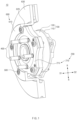
- FIG. 1 is a perspective view illustrating an in-wheel driving device according to an embodiment of the present invention.
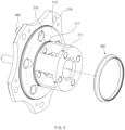
- FIG. 2 is an exploded perspective view illustrating the in-wheel driving device of FIG. 1 according to an embodiment of the present invention.
- FIG. 3 is a perspective view illustrating a carrier and a sealing member according to an embodiment of the present invention.
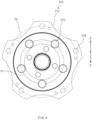
- FIG. 4 is a plan view illustrating the carrier according to an embodiment of the present invention.
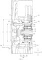
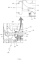
- FIG. 5 is a sectional view illustrating the in-wheel driving device according to an embodiment of the present invention.
- FIG. 6 is an enlarged sectional view of a portion of FIG. 5 .
- FIG. 7 is an enlarged sectional view of a portion ofFIG. 5.
- the in-wheel driving device 10 is a device provided in a wheel 20 to drive the wheel 20.
- the in-wheel driving device 10 includes a wheel bearing 100, a speed reducer 200, the sealing member 300, and wheel bolts 400.
- the wheel bearing 100 includes a hub 110 and an outer ring 130 disposed outward of the hub 110 in a radial direction R.
- the outer ring 130 may be a rotating component
- the hub 110 may be a non-rotating component.
- the in-wheel driving device 10 may include a motor (not illustrated) that generates a rotational force, and the outer ring 130 may be connected to an input shaft directly or indirectly connected to the motor and may be rotated by a driving force of the motor.
- the speed reducer 200 includes the carrier 210 coupled to the wheel 20.
- the speed reducer 200 may be accommodated in the wheel bearing 100 and may include a plurality of gears supported by the carrier 210.
- the speed reducer 200 may be connected with the input shaft and may operate in conjunction with the motor.
- the speed reducer 200 may receive the rotational force generated by the motor and may reduce and output the rotational force.
- the power reduced by the speed reducer 200 may be transmitted to the wheel bearing 100.
- the sealing member 300 may be disposed between the hub 110 and the carrier 210, may be brought into close contact with the carrier 210, and may be formed in an annular shape.
- the lubricant oil for smoothly driving the plurality of gears may be supplied into the speed reducer 200, and the sealing member 300 may serve to seal the lubricant oil in the speed reducer 200. Furthermore, the sealing member 300 may prevent infiltration of external foreign matter into the speed reducer 200.
- the sealing member 300 may be formed in an annular shape to surround the periphery of the speed reducer 200.
- the sealing member 300 may be formed of an elastic material such as rubber.
- the material of the sealing member 300 is not limited thereto.
- the wheel bolts 400 are provided to couple the wheel 20 and the carrier 210 and pass through a plurality of wheel bolt holes 216 that are formed in the carrier 210 so as to be spaced apart from each other in a circumferential direction.
- the wheel bolts 400 may be members that directly connect the carrier 210 with the wheel 20 and may be sequentially coupled to the carrier 210 and the wheel 20.
- the plurality of wheel bolt holes 216 may be formed in the carrier 210 so as to be spaced apart from each other in the circumferential direction, and through-holes corresponding to the wheel bolt holes 216 may be formed in the wheel 20.
- the wheel bolts 400 may pass through the wheel bolt holes 216 and the through-holes and may couple the wheel 20 and the carrier 210.
- the output of the speed reducer 200 may be directly transmitted to the wheel 20, and thus an existing wheel may be used as it is even when the in-wheel driving system according to the present invention is applied.
- a wheel is fastened with a wheel bearing and a speed reducer is embedded in the wheel bearing. Therefore, the size of the wheel bearing is increased, and the pitch circle diameter (PCD) of wheel bolts coupling the wheel and the wheel bearing is also increased. Due to this, the existing wheel cannot be used, and a wheel for the in-wheel driving system has to be separately manufactured.
- PCD pitch circle diameter
- the wheel bolts 400 are coupled to the wheel 20 and the carrier 210, and thus the wheel 20 and the carrier 210 may be directly coupled.
- the outer diameter of the carrier 210 may be expanded to correspond to the outer diameter of the wheel bearing 100.
- the output of the speed reducer 200 may be directly transmitted to the wheel 20 via a sun gear 220 to be described below, the carrier 210, and the wheel bolts 400.
- the carrier 210 may be directly coupled to the wheel 20, and thus the positions of the wheel bolts 400 may not be changed even when the size of the wheel bearing 100 is increased due to the speed reducer 200.
- the PCD of the wheel bolts 400 may be the same as an existing one. As a result, the existing wheel may be used as it is, and due to this, an unnecessary increase in cost may be prevented.
- the sealing member 300 is concentric with a first virtual circle P1 passing through the centers of the plurality of wheel bolt holes 216. That is, the center of the first virtual circle P1 and the center of the sealing member 300 may coincide with each other, and the centers may be located on the central axis of the wheel bearing 100.
- the diameter A of the first virtual circle P1 may be formed to be larger than the diameter B of the sealing member 300 such that the wheel bolts 400 are located outward of the sealing member 300 in the radial direction R (refer to FIG. 5 ).
- the diameter B of the sealing member 300 may be formed to be smaller than the diameter A of the first virtual circle P1. This is because it may be difficult to seal the lubricant oil in the speed reducer 200 when the wheel bolts 400 that pass through the carrier 210 and that are fastened to the wheel 20 are disposed inward of the sealing member 300. Accordingly, according to the present invention, the position in which the sealing member 300 is brought into close contact with the carrier 210 may be distinguished from the mounting positions of the wheel bolts 400 and may be located inward of the wheel bolts 400.
- the position in which the sealing member 300 is brought into close contact with the carrier 210 refers to the position in which the sealing member 300 and the carrier 210 make contact with each other.
- the lubricant oil supplied into the speed reducer 200 may be effectively sealed.
- the direction from the wheel bearing 100 toward the wheel bolts 400 based on the direction of the central axis of the wheel bearing 100 is defined as the first direction D1
- the direction opposite to the first direction D1 is defined as the second direction D2.
- the carrier 210 may include a carrier body 211 and a carrier flange 215.
- the carrier body 211 may be provided such that the plurality of gears included in the speed reducer 200 are mounted therein.
- the carrier flange 215 may be formed on an end portion of the carrier body 211 in the first direction D1, may extend from the carrier body 211 in the radial direction R, and may have the wheel bolt holes 216 formed therein.
- the carrier flange 215 may be expanded from the carrier body 211 in the radial direction R so as to be larger than the pitch circle diameter (PCD) of wheel volts mounted to an existing wheel.
- the carrier 210 may be directly coupled to the wheel 20 by the expanded carrier flange 215.
- the wheel bolts 400 may be mounted on the carrier flange 215, and the sealing member 300 may be brought into close contact with the carrier flange 215.
- the carrier flange 215 may further include a seal close-contact surface 217 that is formed inward of the wheel bolt holes 216 in the radial direction R and with which the sealing member 300 is brought into close contact.
- the seal close-contact surface 217 may be formed parallel to the central axis of the wheel bearing 100, but is not limited thereto.
- the speed reducer 200 may further include the sun gear 220, a ring gear 240, and a planetary gear 230 that are connected to the carrier 210.
- the sun gear 220 may be connected to the input shaft and may be accommodated in the carrier body 211.
- the sun gear 220 may be directly connected with the input shaft, or may be connected to a transmission shaft 700 of a transmission gear connected to the input shaft.
- the transmission shaft 700 or the input shaft may be spline-coupled with the sun gear 220 and may rotate together the sun gear 220.
- the ring gear 240 may be provided in the wheel bearing 100. Specifically, the outer circumferential surface of the ring gear 240 may be brought into close contact with the inner circumferential surface of the hub 110. Accordingly, the ring gear 240 may be a non-rotating component together with the hub 110.
- the planetary gear 230 may be engaged between the sun gear 220 and the ring gear 240 and may be supported by the carrier body 211. Specifically, the planetary gear 230 may be installed through the inside and outside of the carrier body 211 and may be engaged between the sun gear 220 and the ring gear 240. The planetary gear 230 may rotate while revolving around the sun gear 220 when the sun gear 220 rotates. A rotary shaft of the planetary gear 230 may be installed in the carrier 210, and the carrier 210 may rotate together when the planetary gear 230 revolves. A rotational force of the carrier 210 may be transmitted to the wheel 20 by the wheel bolts 400.
- the sealing member 300 may be divided into a first close-contact part 310 and a second close-contact part 320.
- the first close-contact part 310 may be brought into close contact with the seal close-contact surface 217.
- the first close-contact part 310 may extend from an end portion of the second close-contact part 320 in the second direction D2 and may be brought into close contact with the outer circumferential surface of the ring gear 240.
- the sealing member 300 may be mounted on the ring gear 240 and may be brought into close contact with the carrier 210. Accordingly, the sealing member 300 is fixed together with the ring gear 240 that is a non-rotating component, and the carrier 210 is rotated in the state of being brought into close contact with the sealing member 300.
- the sealing member 300 may seal between the carrier 210 and the ring gear 240. Accordingly, leakage of the lubricant oil introduced into the speed reducer 200 may be effectively prevented.
- the shape of the sealing member 300 is not limited to the above-described example, and various changes and modifications can be made as long as the sealing member 300 is capable of sealing between the carrier 210 and the ring gear 240.
- the in-wheel driving device 10 further includes fastening bolts 500.
- the fastening bolts 500 couple the carrier 210 and the wheel bearing 100.
- the carrier flange 215 further includes a plurality of fastening holes 218 that are formed to be spaced apart from each other in the circumferential direction and through which the fastening bolts 500 pass.
- the in-wheel driving device 10 further includes the fastening bolts 500, and the fastening bolts 500 serve to couple the carrier 210 and the wheel bearing 100.
- the position of the PCD of the wheel bolts 400 needs to remain constant irrespective of a change in the size of the wheel bearing 100 depending on the speed reducer 200, and therefore a limitation on the positions of the fastening bolts 500 is required.
- a second virtual circle P2 passing through the centers of the plurality of fastening holes 218 may be concentric with the first virtual circle P1, and the diameter C of the second virtual circle P2 may be formed to be larger than the diameter A of the first virtual circle P1.
- the wheel bolts 400 may be disposed on the carrier 210 so as to be located inward of the fastening bolts 500 and may be installed at predetermined positions irrespective of the size of the wheel bearing 100 to which the fastening bolts 500 are fastened.
- the outer ring 130 may include an outer ring body 131 and an outer ring flange 135.
- the outer ring body 131 may support the hub 110 and may be rotatable relative to the hub 110 with a rolling component 150 between the outer ring body 131 and the hub 110.
- the outer ring flange 135 may extend from the outer surface of the outer ring body 131 in the radial direction R and may have coupling holes 136 formed therein through which the fastening bolts 500 pass. The fastening bolts 500 may be fastened through the coupling holes 136 and the fastening holes 218 to couple the outer ring 130 and the carrier 210.
- the in-wheel driving device 10 may further include the transmission shaft 700 configured to receive power from the input shaft of the sun gear 220.
- the speed reducer 200 may further include a support bearing 250, and the support bearing 250 may be provided between an end portion of the transmission shaft 700 in the first direction D1 and the inner surface of the carrier 210. Thus, deformation of the carrier 210 by the load of the wheel 20 may be minimized.
- the carrier 210 may be deformed by the load of the wheel 20.
- the planetary gear 230 may be eccentric between the sun gear 220 and the ring gear 240, and therefore noise and degradation in durability may occur.
- the transmission shaft 700 of the transmission gear directly or indirectly connected with the input shaft and installed in the motor housing may extend to an end portion of the carrier 210 that faces the first direction D1, and the support bearing 250 may be provided between the end portion of the transmission shaft 700 in the first direction D1 and the inner surface of the carrier 210 to support the carrier 210.
- deformation of the carrier 210 by the load of the wheel 20 may be minimized.
- the in-wheel driving device 10 may further include a disk brake configured to provide a brake force to the wheel 20.
- the disk brake may further include a disk 600, a pad (not illustrated), and a hydraulic device (not illustrated).
- the disk 600 may be coupled to the carrier 210 and the outer ring 130 through the fastening bolts 500 and may rotate together with the carrier 210.
- the pad may be brought into close contact with the disk 600 to generate a frictional force.
- the hydraulic device may bring the pad into close contact with the disk 600 and may include, for example, a cylinder and a caliper.
- the pad may apply a brake force to the wheel 20 while being brought into close contact with or spaced apart from the disk 600 by the hydraulic device.
- the disk 600 may include a coupling portion 610, an extending portion 620, and a frictional portion 630.
- the coupling portion 610 may be coupled to the carrier 210 and may extend in the radial direction R, and the extending portion 620 may extend in the second direction D2 from an end portion of the coupling portion 610 that faces the radial direction R.
- the frictional portion 630 may extend from the extending portion 620 in the radial direction R and may be brought into close contact with the pad.
- the outer ring 130, the carrier 210, and the coupling portion 610 of the disk 600 may be sequentially coupled in the first direction D1 by the fastening bolts 500.
- a support surface 621 brought into close contact with an end portion of the outer ring flange 135 that faces the radial direction R may be provided on the inner surface of the extending portion 620.
- the disk brake may be centered on the wheel bearing 100.
- a wheel bearing and a wheel are directly coupled, and a disk has a structure interposed and coupled between the wheel bearing and the wheel.
- a support surface for centering the disk is provided inward of the PCD of wheel bolts.
- the disk 600 is coupled with the outer ring 130 of the wheel bearing 100 by the fastening bolts 500 passing through the carrier 210, and the PCD of the fastening bolts 500 is formed to be larger than the PCD of the wheel bolts 400. Accordingly, a support portion for centering the disk brake needs to be provided outward of the fastening bolts 500.
- the outer ring 130 may be supported on the support surface 621 of the extending portion 620 of the disk 600.
- the disk brake may be coupled while the outer ring flange 135 is brought into close contact with the support surface 621 and the disk brake is concentric with the wheel bearing 100 and the carrier 210.
- the wheel and the carrier may be directly coupled by the wheel bolts. Accordingly, the in-wheel driving device according to the embodiment of the present invention may use an existing wheel as it is, thereby preventing an unnecessary increase in cost.
- the in-wheel driving device may effectively seal the lubricant oil supplied into the speed reducer.
- the present invention has been made to solve the above-mentioned problems occurring in the prior art while advantages achieved by the prior art are maintained intact.
- An aspect of the present invention provides an in-wheel driving device for preventing an unnecessary increase in cost by using an existing wheel as it is in an in-wheel driving system.
- Another aspect of the present invention provides an in-wheel driving device for effectively sealing lubricant oil supplied into a speed reducer.
- the present invention when the planetary gear is disposed in the wheel bearing, the outer diameter of the wheel bearing may be increased, and therefore the pitch circle diameter (PCD) of the wheel bolts fastening the wheel and the wheel bearing may be increased.
- the PCD may be the diameter of a pitch circle passing through the centers of wheel bolt fastening holes arranged in the circumferential direction.
- an existing standard wheel cannot be used, and a dedicated special wheel for an in-wheel system may have to be manufactured.
- the present invention provides a technology for applying an existing mass-produced wheel as it is by making the PCD of wheel bolts the same as an existing PCD while increasing a speed reduction ratio using a plurality of gears is required.
- the present invention may eliminate the requirement of a dedicated special wheel.
Landscapes
- Engineering & Computer Science (AREA)
- Mechanical Engineering (AREA)
- General Engineering & Computer Science (AREA)
- Chemical & Material Sciences (AREA)
- Combustion & Propulsion (AREA)
- Transportation (AREA)
- Rolling Contact Bearings (AREA)
- Arrangement Or Mounting Of Propulsion Units For Vehicles (AREA)
- Retarders (AREA)
Description
- The present invention relates to an in-wheel driving device, and more particularly, relates to an in-wheel driving device for coupling a wheel and a carrier.
- An in-wheel driving device is a technology used in a vehicle (such as an electric vehicle) that uses electricity as a power source. The in-wheel driving device is a technology for directly driving a wheel with a motor provided in the wheel, unlike the method in which a wheel is rotated by transmission of power through an engine, a transmission, and a drive shaft in a gasoline or diesel vehicle.
- Because the motor and a speed reducer that constitute the in-wheel driving device are disposed in the wheel together with existing parts, such as a suspension device, a steering device, a brake device, and the like, it is important to dispose the motor and the speed reducer in the wheel without interference with the existing parts by minimizing the sizes of the motor and the speed reducer while securing sufficient output and torque.
- The speed reducer including a planetary gear may be mounted in a wheel bearing, and the wheel bearing may be coupled to the wheel through wheel bolts. The output torque of the speed reducer is transmitted to the wheel bearing, and the output of the speed reducer transmitted to the wheel bearing is transmitted to the wheel through the wheel bolts.
-
WO 2013/047695 A1 discloses a bearing device for a wheel provided with a built-in in-wheel motor. In the document it is disclosed that a speed reducer is configured from a planetary gear comprising a sun gear which is provided to the outer periphery of an input shaft, a ring gear which is affixed to a housing, and pinion gears which are disposed at equal intervals in the circumferential direction, an output member is provided with: a joint shaft section which is inserted into a hub ring and which has an outer periphery fitted to the hub ring, an annular base section which is formed to have a large diameter on the inside of the joint shaft section, a pair of flanges which protrudes outward in the radial direction from the annular base section so as to face each other in the axial direction and which contains the pinion gears between the pair of flanges, and a holding section which comprises a bridge for connecting the pair of flanges to each other in the axial direction, a side surface of the holding section is made to be in contact with the large end surface of an inner ring so as to be abutted thereto, and the output member is affixed to the hub ring by an affixation nut so that torque can be transmitted between the output member and the hub ring. -
US 7 556 580 B2 discloses a motor-driven wheel driving apparatus having a wheel bearing, a planetary reduction gear, a driving section with an electric motor to drive the planetary reduction gear, and a rotation member. In the document the wheel bearing is described to include a wheel hub, an inner ring, an outer member and double row rolling elements arranged between the inner and outer raceway surfaces, the planetary reduction gear is described to include an input element, a stationary element, a plurality of planetary, and an output element to rotatably support the planetary elements relative to a connecting shaft, the driving section forming the electric motor is described to have a stator housing, a stator portion contained within the stator housing, and a rotor portion secured on the rotation member arranged opposite to the stator portion via a predetermined air gap, the connecting shaft is removably and torque-transmittably connected to the wheel hub, and the connecting shaft is adapted to drive the wheel by transmitting the rotation of the electric motor to the wheel hub via the planetary reduction gear. -
US 10 876 596 B1 - This Summary is provided to introduce a selection of concepts in a simplified form that are further described below in the Detailed Description. The invention is defined in the appended claims.
-
-
FIG. 1 is a perspective view illustrating an in-wheel driving device according to an embodiment of the present disclosure. -
FIG. 2 is an exploded perspective view illustrating the in-wheel driving device ofFIG. 1 according to an embodiment of the present disclosure. -
FIG. 3 is a perspective view illustrating a carrier and a sealing member according to an embodiment of the present disclosure. -
FIG. 4 is a plan view illustrating the carrier according to an embodiment of the present disclosure. -
FIG. 5 is a sectional view illustrating the in-wheel driving device according to an embodiment of the present disclosure. -
FIG. 6 is an enlarged sectional view of a portion ofFIG. 5 . -
FIG. 7 is an enlarged sectional view of a portion ofFIG. 5 . - Throughout the drawings and the detailed description, unless otherwise described or provided, the same drawing reference numerals will be understood to refer to the same elements, features, and structures. The drawings may not be to scale, and the relative size, proportions, and depiction of elements in the drawings may be exaggerated for clarity, illustration, and convenience.
- The following detailed description is provided to assist the reader in gaining a comprehensive understanding of the device
- Advantages and features of the present invention will be clear with reference to embodiments described in detail below together with the accompanying drawings.
- Terms, such as first, second, A, B, (a), (b) or the like, may be used herein to describe components. Each of these terminologies is not used to define an essence, order or sequence of a corresponding component but used merely to distinguish the corresponding component from other component(s). For example, a first component may be referred to as a second component, and similarly the second component may also be referred to as the first component.
- Throughout the specification, when a component is described as being "connected to," or "coupled to" another component, it may be directly "connected to," or "coupled to" the other component, or there may be one or more other components intervening therebetween. In contrast, when an element is described as being "directly connected to," or "directly coupled to" another element, there can be no other elements intervening therebetween.
- The singular forms "a", "an", and "the" are intended to include the plural forms as well, unless the context clearly indicates otherwise. It will be further understood that the terms "comprises/comprising" and/or "includes/including" when used herein, specify the presence of stated features, integers, steps, operations, elements, and/or components, but do not preclude the presence or addition of one or more other features, integers, steps, operations, elements, components and/or groups thereof.
-
FIG. 1 is a perspective view illustrating an in-wheel driving device according to an embodiment of the present invention.FIG. 2 is an exploded perspective view illustrating the in-wheel driving device ofFIG. 1 according to an embodiment of the present invention.FIG. 3 is a perspective view illustrating a carrier and a sealing member according to an embodiment of the present invention.FIG. 4 is a plan view illustrating the carrier according to an embodiment of the present invention.FIG. 5 is a sectional view illustrating the in-wheel driving device according to an embodiment of the present invention.FIG. 6 is an enlarged sectional view of a portion ofFIG. 5 .FIG. 7 is an enlarged sectional view of a portion ofFIG. 5. - Referring to
FIGS. 1 to 6 , the in-wheel driving device 10 according to an embodiment of the present invention is a device provided in awheel 20 to drive thewheel 20. The in-wheel driving device 10 includes a wheel bearing 100, aspeed reducer 200, thesealing member 300, andwheel bolts 400. - The wheel bearing 100 includes a
hub 110 and anouter ring 130 disposed outward of thehub 110 in a radial direction R. Here, theouter ring 130 may be a rotating component, and thehub 110 may be a non-rotating component. The in-wheel driving device 10 may include a motor (not illustrated) that generates a rotational force, and theouter ring 130 may be connected to an input shaft directly or indirectly connected to the motor and may be rotated by a driving force of the motor. - The
speed reducer 200 includes thecarrier 210 coupled to thewheel 20. Thespeed reducer 200 may be accommodated in the wheel bearing 100 and may include a plurality of gears supported by thecarrier 210. Thespeed reducer 200 may be connected with the input shaft and may operate in conjunction with the motor. Thespeed reducer 200 may receive the rotational force generated by the motor and may reduce and output the rotational force. The power reduced by thespeed reducer 200 may be transmitted to the wheel bearing 100. - To seal lubricant oil supplied into the
speed reducer 200, thesealing member 300 may be disposed between thehub 110 and thecarrier 210, may be brought into close contact with thecarrier 210, and may be formed in an annular shape. - Specifically, the lubricant oil for smoothly driving the plurality of gears may be supplied into the
speed reducer 200, and thesealing member 300 may serve to seal the lubricant oil in thespeed reducer 200. Furthermore, the sealingmember 300 may prevent infiltration of external foreign matter into thespeed reducer 200. The sealingmember 300 may be formed in an annular shape to surround the periphery of thespeed reducer 200. For example, the sealingmember 300 may be formed of an elastic material such as rubber. However, the material of the sealingmember 300 is not limited thereto. - The
wheel bolts 400 are provided to couple thewheel 20 and thecarrier 210 and pass through a plurality ofwheel bolt holes 216 that are formed in thecarrier 210 so as to be spaced apart from each other in a circumferential direction. - Specifically, the
wheel bolts 400 may be members that directly connect thecarrier 210 with thewheel 20 and may be sequentially coupled to thecarrier 210 and thewheel 20. The plurality ofwheel bolt holes 216 may be formed in thecarrier 210 so as to be spaced apart from each other in the circumferential direction, and through-holes corresponding to thewheel bolt holes 216 may be formed in thewheel 20. Thewheel bolts 400 may pass through thewheel bolt holes 216 and the through-holes and may couple thewheel 20 and thecarrier 210. - Accordingly, the output of the
speed reducer 200 may be directly transmitted to thewheel 20, and thus an existing wheel may be used as it is even when the in-wheel driving system according to the present invention is applied. Specifically, in the case of an in-wheel driving system in the related art, a wheel is fastened with a wheel bearing and a speed reducer is embedded in the wheel bearing. Therefore, the size of the wheel bearing is increased, and the pitch circle diameter (PCD) of wheel bolts coupling the wheel and the wheel bearing is also increased. Due to this, the existing wheel cannot be used, and a wheel for the in-wheel driving system has to be separately manufactured. - According to the present invention, the
wheel bolts 400 are coupled to thewheel 20 and thecarrier 210, and thus thewheel 20 and thecarrier 210 may be directly coupled. To this end, the outer diameter of thecarrier 210 may be expanded to correspond to the outer diameter of thewheel bearing 100. In this case, the output of thespeed reducer 200 may be directly transmitted to thewheel 20 via asun gear 220 to be described below, thecarrier 210, and thewheel bolts 400. Furthermore, thecarrier 210 may be directly coupled to thewheel 20, and thus the positions of thewheel bolts 400 may not be changed even when the size of the wheel bearing 100 is increased due to thespeed reducer 200. Accordingly, the PCD of thewheel bolts 400 may be the same as an existing one. As a result, the existing wheel may be used as it is, and due to this, an unnecessary increase in cost may be prevented. - The sealing
member 300 is concentric with a first virtual circle P1 passing through the centers of the plurality of wheel bolt holes 216. That is, the center of the first virtual circle P1 and the center of the sealingmember 300 may coincide with each other, and the centers may be located on the central axis of thewheel bearing 100. - The diameter A of the first virtual circle P1 may be formed to be larger than the diameter B of the sealing
member 300 such that thewheel bolts 400 are located outward of the sealingmember 300 in the radial direction R (refer toFIG. 5 ). - In other words, the diameter B of the sealing
member 300 may be formed to be smaller than the diameter A of the first virtual circle P1. This is because it may be difficult to seal the lubricant oil in thespeed reducer 200 when thewheel bolts 400 that pass through thecarrier 210 and that are fastened to thewheel 20 are disposed inward of the sealingmember 300. Accordingly, according to the present invention, the position in which the sealingmember 300 is brought into close contact with thecarrier 210 may be distinguished from the mounting positions of thewheel bolts 400 and may be located inward of thewheel bolts 400. Here, the position in which the sealingmember 300 is brought into close contact with thecarrier 210 refers to the position in which the sealingmember 300 and thecarrier 210 make contact with each other. Thus, the lubricant oil supplied into thespeed reducer 200 may be effectively sealed. - Hereinafter, the direction from the wheel bearing 100 toward the
wheel bolts 400 based on the direction of the central axis of the wheel bearing 100 is defined as the first direction D1, and the direction opposite to the first direction D1 is defined as the second direction D2. - The
carrier 210 may include acarrier body 211 and acarrier flange 215. - The
carrier body 211 may be provided such that the plurality of gears included in thespeed reducer 200 are mounted therein. - The
carrier flange 215 may be formed on an end portion of thecarrier body 211 in the first direction D1, may extend from thecarrier body 211 in the radial direction R, and may have the wheel bolt holes 216 formed therein. - The
carrier flange 215 may be expanded from thecarrier body 211 in the radial direction R so as to be larger than the pitch circle diameter (PCD) of wheel volts mounted to an existing wheel. Thecarrier 210 may be directly coupled to thewheel 20 by the expandedcarrier flange 215. Thewheel bolts 400 may be mounted on thecarrier flange 215, and the sealingmember 300 may be brought into close contact with thecarrier flange 215. - Specifically, the
carrier flange 215 may further include a seal close-contact surface 217 that is formed inward of the wheel bolt holes 216 in the radial direction R and with which the sealingmember 300 is brought into close contact. For example, the seal close-contact surface 217 may be formed parallel to the central axis of thewheel bearing 100, but is not limited thereto. - The
speed reducer 200 may further include thesun gear 220, aring gear 240, and aplanetary gear 230 that are connected to thecarrier 210. - The
sun gear 220 may be connected to the input shaft and may be accommodated in thecarrier body 211. For example, thesun gear 220 may be directly connected with the input shaft, or may be connected to atransmission shaft 700 of a transmission gear connected to the input shaft. Thetransmission shaft 700 or the input shaft may be spline-coupled with thesun gear 220 and may rotate together thesun gear 220. - The
ring gear 240 may be provided in thewheel bearing 100. Specifically, the outer circumferential surface of thering gear 240 may be brought into close contact with the inner circumferential surface of thehub 110. Accordingly, thering gear 240 may be a non-rotating component together with thehub 110. - The
planetary gear 230 may be engaged between thesun gear 220 and thering gear 240 and may be supported by thecarrier body 211. Specifically, theplanetary gear 230 may be installed through the inside and outside of thecarrier body 211 and may be engaged between thesun gear 220 and thering gear 240. Theplanetary gear 230 may rotate while revolving around thesun gear 220 when thesun gear 220 rotates. A rotary shaft of theplanetary gear 230 may be installed in thecarrier 210, and thecarrier 210 may rotate together when theplanetary gear 230 revolves. A rotational force of thecarrier 210 may be transmitted to thewheel 20 by thewheel bolts 400. - The sealing
member 300 may be divided into a first close-contact part 310 and a second close-contact part 320. - The first close-
contact part 310 may be brought into close contact with the seal close-contact surface 217. The first close-contact part 310 may extend from an end portion of the second close-contact part 320 in the second direction D2 and may be brought into close contact with the outer circumferential surface of thering gear 240. The sealingmember 300 may be mounted on thering gear 240 and may be brought into close contact with thecarrier 210. Accordingly, the sealingmember 300 is fixed together with thering gear 240 that is a non-rotating component, and thecarrier 210 is rotated in the state of being brought into close contact with the sealingmember 300. - Due to this structure, the sealing
member 300 may seal between thecarrier 210 and thering gear 240. Accordingly, leakage of the lubricant oil introduced into thespeed reducer 200 may be effectively prevented. However, the shape of the sealingmember 300 is not limited to the above-described example, and various changes and modifications can be made as long as the sealingmember 300 is capable of sealing between thecarrier 210 and thering gear 240. - The in-
wheel driving device 10 according to the present invention further includesfastening bolts 500. Thefastening bolts 500 couple thecarrier 210 and thewheel bearing 100. Thecarrier flange 215 further includes a plurality offastening holes 218 that are formed to be spaced apart from each other in the circumferential direction and through which thefastening bolts 500 pass. - Specifically, because the output of the
speed reducer 200 is directly transmitted to thewheel 20 by thewheel bolts 400, a component capable of transmitting the output of thespeed reducer 200 to the wheel bearing 100 is required. Accordingly, the in-wheel driving device 10 according to the present disclosure further includes thefastening bolts 500, and thefastening bolts 500 serve to couple thecarrier 210 and thewheel bearing 100. However, as described above, the position of the PCD of thewheel bolts 400 needs to remain constant irrespective of a change in the size of the wheel bearing 100 depending on thespeed reducer 200, and therefore a limitation on the positions of thefastening bolts 500 is required. - Accordingly, a second virtual circle P2 passing through the centers of the plurality of
fastening holes 218 may be concentric with the first virtual circle P1, and the diameter C of the second virtual circle P2 may be formed to be larger than the diameter A of the first virtual circle P1. - The
wheel bolts 400 may be disposed on thecarrier 210 so as to be located inward of thefastening bolts 500 and may be installed at predetermined positions irrespective of the size of the wheel bearing 100 to which thefastening bolts 500 are fastened. - The
outer ring 130 may include anouter ring body 131 and anouter ring flange 135. - The
outer ring body 131 may support thehub 110 and may be rotatable relative to thehub 110 with a rollingcomponent 150 between theouter ring body 131 and thehub 110. Theouter ring flange 135 may extend from the outer surface of theouter ring body 131 in the radial direction R and may havecoupling holes 136 formed therein through which thefastening bolts 500 pass. Thefastening bolts 500 may be fastened through the coupling holes 136 and the fastening holes 218 to couple theouter ring 130 and thecarrier 210. - The in-
wheel driving device 10 according to the present invention may further include thetransmission shaft 700 configured to receive power from the input shaft of thesun gear 220. Thespeed reducer 200 may further include asupport bearing 250, and the support bearing 250 may be provided between an end portion of thetransmission shaft 700 in the first direction D1 and the inner surface of thecarrier 210. Thus, deformation of thecarrier 210 by the load of thewheel 20 may be minimized. - Specifically, because the
carrier 210 and thewheel 20 are directly coupled by thewheel bolts 400 to transmit a driving force, thecarrier 210 may be deformed by the load of thewheel 20. When thecarrier 210 is deformed, theplanetary gear 230 may be eccentric between thesun gear 220 and thering gear 240, and therefore noise and degradation in durability may occur. - Accordingly, the
transmission shaft 700 of the transmission gear directly or indirectly connected with the input shaft and installed in the motor housing may extend to an end portion of thecarrier 210 that faces the first direction D1, and the support bearing 250 may be provided between the end portion of thetransmission shaft 700 in the first direction D1 and the inner surface of thecarrier 210 to support thecarrier 210. Thus, deformation of thecarrier 210 by the load of thewheel 20 may be minimized. - The in-
wheel driving device 10 according to the present invention may further include a disk brake configured to provide a brake force to thewheel 20. - The disk brake may further include a
disk 600, a pad (not illustrated), and a hydraulic device (not illustrated). - The
disk 600 may be coupled to thecarrier 210 and theouter ring 130 through thefastening bolts 500 and may rotate together with thecarrier 210. The pad may be brought into close contact with thedisk 600 to generate a frictional force. - The hydraulic device may bring the pad into close contact with the
disk 600 and may include, for example, a cylinder and a caliper. The pad may apply a brake force to thewheel 20 while being brought into close contact with or spaced apart from thedisk 600 by the hydraulic device. - Specifically, the
disk 600 may include acoupling portion 610, an extendingportion 620, and africtional portion 630. - The
coupling portion 610 may be coupled to thecarrier 210 and may extend in the radial direction R, and the extendingportion 620 may extend in the second direction D2 from an end portion of thecoupling portion 610 that faces the radial direction R. Thefrictional portion 630 may extend from the extendingportion 620 in the radial direction R and may be brought into close contact with the pad. - At this time, the
outer ring 130, thecarrier 210, and thecoupling portion 610 of thedisk 600 may be sequentially coupled in the first direction D1 by thefastening bolts 500. - A
support surface 621 brought into close contact with an end portion of theouter ring flange 135 that faces the radial direction R may be provided on the inner surface of the extendingportion 620. - Specifically, as the end portion of the
outer ring flange 135 that faces the radial direction R is brought into close contact with thesupport surface 621 provided on the inner surface of the extendingportion 620 of thedisk 600, a central portion of thedisk 600 may coincide with a central portion of theouter ring 130. Accordingly, the disk brake may be centered on thewheel bearing 100. More specifically, in the related art, a wheel bearing and a wheel are directly coupled, and a disk has a structure interposed and coupled between the wheel bearing and the wheel. In this case, a support surface for centering the disk is provided inward of the PCD of wheel bolts. However, separately from thewheel 20, thedisk 600 is coupled with theouter ring 130 of the wheel bearing 100 by thefastening bolts 500 passing through thecarrier 210, and the PCD of thefastening bolts 500 is formed to be larger than the PCD of thewheel bolts 400. Accordingly, a support portion for centering the disk brake needs to be provided outward of thefastening bolts 500. To center the disk brake, theouter ring 130 may be supported on thesupport surface 621 of the extendingportion 620 of thedisk 600. Thus, when the disk brake is coupled with thewheel bearing 100 and thecarrier 210, the disk brake may be coupled while theouter ring flange 135 is brought into close contact with thesupport surface 621 and the disk brake is concentric with thewheel bearing 100 and thecarrier 210. - As described above, the wheel and the carrier may be directly coupled by the wheel bolts. Accordingly, the in-wheel driving device according to the embodiment of the present invention may use an existing wheel as it is, thereby preventing an unnecessary increase in cost.
- In addition, according to the present invention, the in-wheel driving device may effectively seal the lubricant oil supplied into the speed reducer.
- The present invention has been made to solve the above-mentioned problems occurring in the prior art while advantages achieved by the prior art are maintained intact.
- An aspect of the present invention provides an in-wheel driving device for preventing an unnecessary increase in cost by using an existing wheel as it is in an in-wheel driving system.
- Another aspect of the present invention provides an in-wheel driving device for effectively sealing lubricant oil supplied into a speed reducer.
- In instances in which the present invention is not implemented, when the planetary gear is disposed in the wheel bearing, the outer diameter of the wheel bearing may be increased, and therefore the pitch circle diameter (PCD) of the wheel bolts fastening the wheel and the wheel bearing may be increased. In these instances, the PCD may be the diameter of a pitch circle passing through the centers of wheel bolt fastening holes arranged in the circumferential direction. When the PCD of the wheel bolts is increased in these instances, an existing standard wheel cannot be used, and a dedicated special wheel for an in-wheel system may have to be manufactured. The present invention provides a technology for applying an existing mass-produced wheel as it is by making the PCD of wheel bolts the same as an existing PCD while increasing a speed reduction ratio using a plurality of gears is required. Thus, the present invention may eliminate the requirement of a dedicated special wheel.
Claims (10)
- An in-wheel driving device (10), the device comprising:a wheel bearing (100) including a hub (110) and an outer ring (130) disposed outward of the hub (110) in a radial direction;a speed reducer (200) including a carrier (210) coupled to a wheel (20);an annular sealing member (300) disposed between the hub (110) and the carrier (210) and brought into close contact with the carrier (210) to seal lubricant oil supplied into the speed reducer (200); andwheel bolts (400) configured to couple the wheel (20) and the carrier (210), wherein the wheel bolts (400) pass through a plurality of wheel bolt holes (216) formed in the carrier (210) spaced apart from each other in a circumferential direction,wherein the sealing member (300) is concentric with a first virtual circle (P1) passing through centers of the plurality of wheel bolt holes (216), andwherein the first virtual circle (P1) has a larger diameter than the sealing member (300) such that the wheel bolts (400) are located outward of the sealing member (300) in the radial direction,wherein the carrier (210) includes:a carrier body (211); anda carrier flange (215) formed on an end portion of the carrier body (211) in a direction from the wheel bearing (100) toward the wheel bolts (400) based on a direction of a central axis of the wheel bearing (100) and configured to extend from the carrier body (211) in the radial direction, the carrier flange (215) having the wheel bolt holes (216) formed therein, andwherein the carrier flange (215) further includes a seal close-contact surface (217) with which the sealing member (300) is brought into close contact, the seal close-contact surface (217) being formed inward of the wheel bolt holes (216) in the radial direction, andwherein the in-wheel driving device (10) further comprises:
fastening bolts (500) configured to couple the carrier (210) and the wheel bearing (100), wherein the carrier flange (215) includes a plurality of fastening holes (218) through which the fastening bolts (500) pass, the plurality of fastening holes (218) being spaced apart from each other in the circumferential direction. - The device (10) of claim 1, wherein the speed reducer (200) further includes:a sun gear (220) connected to an input shaft and accommodated in the carrier body (211);a ring gear (240) provided in the wheel bearing (100); anda planetary gear (230) engaged between the sun gear (220) and the ring gear (240) and supported by the carrier body (211).
- The device (10) of claim 2, wherein an outer circumferential surface of the ring gear (240) is brought into close contact with an inner circumferential surface of the hub (110).
- The device (10) of claim 2 or 3, wherein the seal close-contact surface (217) is formed parallel to the central axis of the wheel bearing (100), and
wherein the sealing member (300) includes:a first close-contact part (310) brought into close contact with the seal close-contact surface (217); anda second close-contact part (320) configured to extend from an end portion of the first close-contact part (310) in a direction opposite to the direction from the wheel bearing (100) toward the wheel bolts (400) and brought into close contact with an outer circumferential surface of the ring gear (240). - The device (10) of claim 1, wherein a second virtual circle (P2) passing through centers of the plurality of fastening holes (218) is concentric with the first virtual circle (P1), and
wherein the second virtual circle (P2) has a larger diameter than the first virtual circle (P1). - The device (10) of claim 1 or 5, wherein the outer ring (130) includes:an outer ring body (131) configured to support the hub (110), the outer ring body (131) being rotatable relative to the hub (110) with a rolling component between the outer ring body (131) and the hub (110); andan outer ring flange (135) configured to extend from an outer surface of the outer ring body (131) in the radial direction, the outer ring flange (135) having coupling holes (136) formed therein through which the fastening bolts (500) pass.
- The device (10) of any one of claims 2 to 6, further comprising:a transmission shaft (700) configured to receive power from the input shaft of the sun gear (220),wherein the speed reducer (200) further includes a support bearing (250) provided between an end portion of the transmission shaft (700) in the direction from the wheel bearing (100) toward the wheel bolts (400) and an inner surface of the carrier (210).
- The device (10) of claim 6 or 7, further comprising:a disk brake configured to provide a brake force to the wheel (20),wherein the disk brake includes:a disk (600) coupled to the carrier (210) and the outer ring (130) through the fastening bolts (500) and configured to rotate together with the carrier (210); anda pad brought into close contact with the disk (600) to generate a frictional force.
- The device (10) of claim 8, wherein the disk (600) includes:a coupling portion (610) coupled to the carrier (210) and configured to extend in the radial direction;an extending portion (620) configured to extend in the direction opposite to the direction from the wheel bearing (100) toward the wheel bolts (400) from an end portion of the coupling portion (610) configured to face the radial direction; anda frictional portion (630) configured to extend from the extending portion (620) in the radial direction and to be brought into close contact with the pad, andwherein a support surface (621) brought into close contact with an end portion of the outer ring flange (135) configured to face the radial direction is provided on an inner surface of the extending portion (620).
- The device (10) of claim 8 or 9, wherein the outer ring (130), the carrier (210), and the disk (600) are sequentially coupled in the direction from the wheel bearing (100) toward the wheel bolts (400) by the fastening bolts (500).
Applications Claiming Priority (1)
| Application Number | Priority Date | Filing Date | Title |
|---|---|---|---|
| KR1020210121225A KR20230038008A (en) | 2021-09-10 | 2021-09-10 | In-wheel driving device |
Publications (2)
| Publication Number | Publication Date |
|---|---|
| EP4147896A1 EP4147896A1 (en) | 2023-03-15 |
| EP4147896B1 true EP4147896B1 (en) | 2024-05-22 |
Family
ID=83271358
Family Applications (1)
| Application Number | Title | Priority Date | Filing Date |
|---|---|---|---|
| EP22194557.9A Active EP4147896B1 (en) | 2021-09-10 | 2022-09-08 | In-wheel driving device |
Country Status (4)
| Country | Link |
|---|---|
| US (1) | US12636951B2 (en) |
| EP (1) | EP4147896B1 (en) |
| KR (1) | KR20230038008A (en) |
| CN (1) | CN218505648U (en) |
Families Citing this family (1)
| Publication number | Priority date | Publication date | Assignee | Title |
|---|---|---|---|---|
| KR102958837B1 (en) * | 2020-07-27 | 2026-04-29 | 현대모비스 주식회사 | In-wheel working device and automobile including the same |
Family Cites Families (13)
| Publication number | Priority date | Publication date | Assignee | Title |
|---|---|---|---|---|
| JP2005231564A (en) * | 2004-02-23 | 2005-09-02 | Ntn Corp | Electric wheel drive device |
| JP2007191019A (en) * | 2006-01-18 | 2007-08-02 | Toyota Motor Corp | Wheel drive device |
| US8132636B2 (en) * | 2006-03-08 | 2012-03-13 | Ntn Corporation | In-wheel motor drive unit |
| US8323143B2 (en) * | 2009-12-02 | 2012-12-04 | Fairfield Manufacturing Company, Inc. | Integrated spindle-carrier electric wheel drive |
| JP5685111B2 (en) * | 2011-03-07 | 2015-03-18 | Ntn株式会社 | Electric vehicle drive |
| EP2698565B1 (en) * | 2011-04-13 | 2016-04-06 | Nissan Motor Co., Ltd | Lubrication control device for in-wheel motor unit for vehicle |
| WO2013047695A1 (en) | 2011-09-28 | 2013-04-04 | Ntn株式会社 | Bearing device for wheel with built-in in-wheel motor |
| JP2013071599A (en) | 2011-09-28 | 2013-04-22 | Ntn Corp | Bearing device for wheel with built-in in-wheel motor |
| JP5799731B2 (en) * | 2011-10-12 | 2015-10-28 | 日産自動車株式会社 | Axle support structure |
| US10066735B1 (en) * | 2017-03-06 | 2018-09-04 | Fairfield Manufacturing Company, Inc. | Planetary wheel drive single wall lugged output carrier |
| EP3778281B1 (en) * | 2018-04-09 | 2023-03-01 | Tsinghua University | Electric wheel assembly with integrated hub motor |
| US10876596B1 (en) | 2018-06-29 | 2020-12-29 | Hydro-Gear Limited Partnership | Electric motor with compound planetary gear drive |
| KR102958837B1 (en) * | 2020-07-27 | 2026-04-29 | 현대모비스 주식회사 | In-wheel working device and automobile including the same |
-
2021
- 2021-09-10 KR KR1020210121225A patent/KR20230038008A/en active Pending
-
2022
- 2022-09-07 US US17/939,355 patent/US12636951B2/en active Active
- 2022-09-08 EP EP22194557.9A patent/EP4147896B1/en active Active
- 2022-09-09 CN CN202222410461.9U patent/CN218505648U/en active Active
Also Published As
| Publication number | Publication date |
|---|---|
| US12636951B2 (en) | 2026-05-26 |
| EP4147896A1 (en) | 2023-03-15 |
| US20230077725A1 (en) | 2023-03-16 |
| CN218505648U (en) | 2023-02-21 |
| KR20230038008A (en) | 2023-03-17 |
Similar Documents
| Publication | Publication Date | Title |
|---|---|---|
| CN113226821B (en) | Wheel hub motor drive system and motor vehicle | |
| CN120226242A (en) | Electric hub drive for a motor vehicle | |
| US20070209853A1 (en) | Vehicular drive unit | |
| WO2013047695A1 (en) | Bearing device for wheel with built-in in-wheel motor | |
| WO2011070882A1 (en) | In-wheel motor drive device | |
| CN120883488A (en) | Electric hub drive for motor vehicles | |
| CN105691103A (en) | Hub driving assembly | |
| EP1763448B1 (en) | Planet transmission and drive device comprising the planet transmission | |
| JP2004517275A (en) | Angle drive with power distribution | |
| EP1446591B1 (en) | Arrangement for driving a wheel of a vehicle which comprises an annular member for a braking device | |
| JP4847968B2 (en) | Differential assembly with welded differential case | |
| US11686376B2 (en) | Connecting section for a two-part hub, a two-part hub and a hybrid drive module | |
| JP6445813B2 (en) | In-wheel motor drive device | |
| EP4147896A1 (en) | In-wheel driving device | |
| CN218750282U (en) | Highly integrated wheel-side driving assembly | |
| JP5913925B2 (en) | Bearing device for wheels with built-in in-wheel motor | |
| CN215474444U (en) | In-wheel drive device and vehicle comprising an in-wheel drive device | |
| CN118665154A (en) | Wheel hub motor drive system and vehicle | |
| CN112638685B (en) | Hub device for a drive wheel of a vehicle | |
| JP2016222062A (en) | Wheel drive braking device | |
| KR102657742B1 (en) | Motor integrated reducer and its assembly method | |
| WO2021095674A1 (en) | In-wheel motor drive device | |
| WO2021105735A1 (en) | Rotary electric machine | |
| CN223794625U (en) | Wheel side speed reduction device and tractor | |
| CN221195789U (en) | Connecting device and vehicle |
Legal Events
| Date | Code | Title | Description |
|---|---|---|---|
| PUAI | Public reference made under article 153(3) epc to a published international application that has entered the european phase |
Free format text: ORIGINAL CODE: 0009012 |
|
| STAA | Information on the status of an ep patent application or granted ep patent |
Free format text: STATUS: REQUEST FOR EXAMINATION WAS MADE |
|
| 17P | Request for examination filed |
Effective date: 20220908 |
|
| AK | Designated contracting states |
Kind code of ref document: A1 Designated state(s): AL AT BE BG CH CY CZ DE DK EE ES FI FR GB GR HR HU IE IS IT LI LT LU LV MC MK MT NL NO PL PT RO RS SE SI SK SM TR |
|
| GRAP | Despatch of communication of intention to grant a patent |
Free format text: ORIGINAL CODE: EPIDOSNIGR1 |
|
| STAA | Information on the status of an ep patent application or granted ep patent |
Free format text: STATUS: GRANT OF PATENT IS INTENDED |
|
| INTG | Intention to grant announced |
Effective date: 20231219 |
|
| GRAS | Grant fee paid |
Free format text: ORIGINAL CODE: EPIDOSNIGR3 |
|
| GRAA | (expected) grant |
Free format text: ORIGINAL CODE: 0009210 |
|
| STAA | Information on the status of an ep patent application or granted ep patent |
Free format text: STATUS: THE PATENT HAS BEEN GRANTED |
|
| P01 | Opt-out of the competence of the unified patent court (upc) registered |
Effective date: 20240325 |
|
| AK | Designated contracting states |
Kind code of ref document: B1 Designated state(s): AL AT BE BG CH CY CZ DE DK EE ES FI FR GB GR HR HU IE IS IT LI LT LU LV MC MK MT NL NO PL PT RO RS SE SI SK SM TR |
|
| RAP3 | Party data changed (applicant data changed or rights of an application transferred) |
Owner name: HYUNDAI MOBIS CO., LTD. |
|
| REG | Reference to a national code |
Ref country code: GB Ref legal event code: FG4D |
|
| REG | Reference to a national code |
Ref country code: CH Ref legal event code: EP |
|
| REG | Reference to a national code |
Ref country code: DE Ref legal event code: R096 Ref document number: 602022003576 Country of ref document: DE |
|
| REG | Reference to a national code |
Ref country code: IE Ref legal event code: FG4D |
|
| REG | Reference to a national code |
Ref country code: LT Ref legal event code: MG9D |
|
| REG | Reference to a national code |
Ref country code: NL Ref legal event code: MP Effective date: 20240522 |
|
| PG25 | Lapsed in a contracting state [announced via postgrant information from national office to epo] |
Ref country code: IS Free format text: LAPSE BECAUSE OF FAILURE TO SUBMIT A TRANSLATION OF THE DESCRIPTION OR TO PAY THE FEE WITHIN THE PRESCRIBED TIME-LIMIT Effective date: 20240922 |
|
| PG25 | Lapsed in a contracting state [announced via postgrant information from national office to epo] |
Ref country code: BG Free format text: LAPSE BECAUSE OF FAILURE TO SUBMIT A TRANSLATION OF THE DESCRIPTION OR TO PAY THE FEE WITHIN THE PRESCRIBED TIME-LIMIT Effective date: 20240522 |
|
| PG25 | Lapsed in a contracting state [announced via postgrant information from national office to epo] |
Ref country code: HR Free format text: LAPSE BECAUSE OF FAILURE TO SUBMIT A TRANSLATION OF THE DESCRIPTION OR TO PAY THE FEE WITHIN THE PRESCRIBED TIME-LIMIT Effective date: 20240522 Ref country code: FI Free format text: LAPSE BECAUSE OF FAILURE TO SUBMIT A TRANSLATION OF THE DESCRIPTION OR TO PAY THE FEE WITHIN THE PRESCRIBED TIME-LIMIT Effective date: 20240522 |
|
| PG25 | Lapsed in a contracting state [announced via postgrant information from national office to epo] |
Ref country code: GR Free format text: LAPSE BECAUSE OF FAILURE TO SUBMIT A TRANSLATION OF THE DESCRIPTION OR TO PAY THE FEE WITHIN THE PRESCRIBED TIME-LIMIT Effective date: 20240823 |
|
| PG25 | Lapsed in a contracting state [announced via postgrant information from national office to epo] |
Ref country code: PT Free format text: LAPSE BECAUSE OF FAILURE TO SUBMIT A TRANSLATION OF THE DESCRIPTION OR TO PAY THE FEE WITHIN THE PRESCRIBED TIME-LIMIT Effective date: 20240923 |
|
| REG | Reference to a national code |
Ref country code: AT Ref legal event code: MK05 Ref document number: 1688500 Country of ref document: AT Kind code of ref document: T Effective date: 20240522 |
|
| PG25 | Lapsed in a contracting state [announced via postgrant information from national office to epo] |
Ref country code: NL Free format text: LAPSE BECAUSE OF FAILURE TO SUBMIT A TRANSLATION OF THE DESCRIPTION OR TO PAY THE FEE WITHIN THE PRESCRIBED TIME-LIMIT Effective date: 20240522 |
|
| PG25 | Lapsed in a contracting state [announced via postgrant information from national office to epo] |
Ref country code: ES Free format text: LAPSE BECAUSE OF FAILURE TO SUBMIT A TRANSLATION OF THE DESCRIPTION OR TO PAY THE FEE WITHIN THE PRESCRIBED TIME-LIMIT Effective date: 20240522 |
|
| PG25 | Lapsed in a contracting state [announced via postgrant information from national office to epo] |
Ref country code: AT Free format text: LAPSE BECAUSE OF FAILURE TO SUBMIT A TRANSLATION OF THE DESCRIPTION OR TO PAY THE FEE WITHIN THE PRESCRIBED TIME-LIMIT Effective date: 20240522 |
|
| PG25 | Lapsed in a contracting state [announced via postgrant information from national office to epo] |
Ref country code: PL Free format text: LAPSE BECAUSE OF FAILURE TO SUBMIT A TRANSLATION OF THE DESCRIPTION OR TO PAY THE FEE WITHIN THE PRESCRIBED TIME-LIMIT Effective date: 20240522 |
|
| PG25 | Lapsed in a contracting state [announced via postgrant information from national office to epo] |
Ref country code: LV Free format text: LAPSE BECAUSE OF FAILURE TO SUBMIT A TRANSLATION OF THE DESCRIPTION OR TO PAY THE FEE WITHIN THE PRESCRIBED TIME-LIMIT Effective date: 20240522 |
|
| PG25 | Lapsed in a contracting state [announced via postgrant information from national office to epo] |
Ref country code: PT Free format text: LAPSE BECAUSE OF FAILURE TO SUBMIT A TRANSLATION OF THE DESCRIPTION OR TO PAY THE FEE WITHIN THE PRESCRIBED TIME-LIMIT Effective date: 20240923 Ref country code: PL Free format text: LAPSE BECAUSE OF FAILURE TO SUBMIT A TRANSLATION OF THE DESCRIPTION OR TO PAY THE FEE WITHIN THE PRESCRIBED TIME-LIMIT Effective date: 20240522 Ref country code: NO Free format text: LAPSE BECAUSE OF FAILURE TO SUBMIT A TRANSLATION OF THE DESCRIPTION OR TO PAY THE FEE WITHIN THE PRESCRIBED TIME-LIMIT Effective date: 20240822 Ref country code: NL Free format text: LAPSE BECAUSE OF FAILURE TO SUBMIT A TRANSLATION OF THE DESCRIPTION OR TO PAY THE FEE WITHIN THE PRESCRIBED TIME-LIMIT Effective date: 20240522 Ref country code: LV Free format text: LAPSE BECAUSE OF FAILURE TO SUBMIT A TRANSLATION OF THE DESCRIPTION OR TO PAY THE FEE WITHIN THE PRESCRIBED TIME-LIMIT Effective date: 20240522 Ref country code: IS Free format text: LAPSE BECAUSE OF FAILURE TO SUBMIT A TRANSLATION OF THE DESCRIPTION OR TO PAY THE FEE WITHIN THE PRESCRIBED TIME-LIMIT Effective date: 20240922 Ref country code: HR Free format text: LAPSE BECAUSE OF FAILURE TO SUBMIT A TRANSLATION OF THE DESCRIPTION OR TO PAY THE FEE WITHIN THE PRESCRIBED TIME-LIMIT Effective date: 20240522 Ref country code: GR Free format text: LAPSE BECAUSE OF FAILURE TO SUBMIT A TRANSLATION OF THE DESCRIPTION OR TO PAY THE FEE WITHIN THE PRESCRIBED TIME-LIMIT Effective date: 20240823 Ref country code: FI Free format text: LAPSE BECAUSE OF FAILURE TO SUBMIT A TRANSLATION OF THE DESCRIPTION OR TO PAY THE FEE WITHIN THE PRESCRIBED TIME-LIMIT Effective date: 20240522 Ref country code: ES Free format text: LAPSE BECAUSE OF FAILURE TO SUBMIT A TRANSLATION OF THE DESCRIPTION OR TO PAY THE FEE WITHIN THE PRESCRIBED TIME-LIMIT Effective date: 20240522 Ref country code: BG Free format text: LAPSE BECAUSE OF FAILURE TO SUBMIT A TRANSLATION OF THE DESCRIPTION OR TO PAY THE FEE WITHIN THE PRESCRIBED TIME-LIMIT Effective date: 20240522 Ref country code: AT Free format text: LAPSE BECAUSE OF FAILURE TO SUBMIT A TRANSLATION OF THE DESCRIPTION OR TO PAY THE FEE WITHIN THE PRESCRIBED TIME-LIMIT Effective date: 20240522 Ref country code: RS Free format text: LAPSE BECAUSE OF FAILURE TO SUBMIT A TRANSLATION OF THE DESCRIPTION OR TO PAY THE FEE WITHIN THE PRESCRIBED TIME-LIMIT Effective date: 20240822 |
|
| PG25 | Lapsed in a contracting state [announced via postgrant information from national office to epo] |
Ref country code: DK Free format text: LAPSE BECAUSE OF FAILURE TO SUBMIT A TRANSLATION OF THE DESCRIPTION OR TO PAY THE FEE WITHIN THE PRESCRIBED TIME-LIMIT Effective date: 20240522 |
|
| PG25 | Lapsed in a contracting state [announced via postgrant information from national office to epo] |
Ref country code: EE Free format text: LAPSE BECAUSE OF FAILURE TO SUBMIT A TRANSLATION OF THE DESCRIPTION OR TO PAY THE FEE WITHIN THE PRESCRIBED TIME-LIMIT Effective date: 20240522 |
|
| PG25 | Lapsed in a contracting state [announced via postgrant information from national office to epo] |
Ref country code: CZ Free format text: LAPSE BECAUSE OF FAILURE TO SUBMIT A TRANSLATION OF THE DESCRIPTION OR TO PAY THE FEE WITHIN THE PRESCRIBED TIME-LIMIT Effective date: 20240522 |
|
| PG25 | Lapsed in a contracting state [announced via postgrant information from national office to epo] |
Ref country code: SK Free format text: LAPSE BECAUSE OF FAILURE TO SUBMIT A TRANSLATION OF THE DESCRIPTION OR TO PAY THE FEE WITHIN THE PRESCRIBED TIME-LIMIT Effective date: 20240522 Ref country code: RO Free format text: LAPSE BECAUSE OF FAILURE TO SUBMIT A TRANSLATION OF THE DESCRIPTION OR TO PAY THE FEE WITHIN THE PRESCRIBED TIME-LIMIT Effective date: 20240522 |
|
| PG25 | Lapsed in a contracting state [announced via postgrant information from national office to epo] |
Ref country code: SK Free format text: LAPSE BECAUSE OF FAILURE TO SUBMIT A TRANSLATION OF THE DESCRIPTION OR TO PAY THE FEE WITHIN THE PRESCRIBED TIME-LIMIT Effective date: 20240522 Ref country code: RO Free format text: LAPSE BECAUSE OF FAILURE TO SUBMIT A TRANSLATION OF THE DESCRIPTION OR TO PAY THE FEE WITHIN THE PRESCRIBED TIME-LIMIT Effective date: 20240522 Ref country code: EE Free format text: LAPSE BECAUSE OF FAILURE TO SUBMIT A TRANSLATION OF THE DESCRIPTION OR TO PAY THE FEE WITHIN THE PRESCRIBED TIME-LIMIT Effective date: 20240522 Ref country code: DK Free format text: LAPSE BECAUSE OF FAILURE TO SUBMIT A TRANSLATION OF THE DESCRIPTION OR TO PAY THE FEE WITHIN THE PRESCRIBED TIME-LIMIT Effective date: 20240522 Ref country code: CZ Free format text: LAPSE BECAUSE OF FAILURE TO SUBMIT A TRANSLATION OF THE DESCRIPTION OR TO PAY THE FEE WITHIN THE PRESCRIBED TIME-LIMIT Effective date: 20240522 |
|
| REG | Reference to a national code |
Ref country code: DE Ref legal event code: R097 Ref document number: 602022003576 Country of ref document: DE |
|
| PLBE | No opposition filed within time limit |
Free format text: ORIGINAL CODE: 0009261 |
|
| STAA | Information on the status of an ep patent application or granted ep patent |
Free format text: STATUS: NO OPPOSITION FILED WITHIN TIME LIMIT |
|
| PG25 | Lapsed in a contracting state [announced via postgrant information from national office to epo] |
Ref country code: SI Free format text: LAPSE BECAUSE OF FAILURE TO SUBMIT A TRANSLATION OF THE DESCRIPTION OR TO PAY THE FEE WITHIN THE PRESCRIBED TIME-LIMIT Effective date: 20240522 Ref country code: MC Free format text: LAPSE BECAUSE OF FAILURE TO SUBMIT A TRANSLATION OF THE DESCRIPTION OR TO PAY THE FEE WITHIN THE PRESCRIBED TIME-LIMIT Effective date: 20240522 |
|
| 26N | No opposition filed |
Effective date: 20250225 |
|
| PG25 | Lapsed in a contracting state [announced via postgrant information from national office to epo] |
Ref country code: LU Free format text: LAPSE BECAUSE OF NON-PAYMENT OF DUE FEES Effective date: 20240908 |
|
| REG | Reference to a national code |
Ref country code: BE Ref legal event code: MM Effective date: 20240930 |
|
| PG25 | Lapsed in a contracting state [announced via postgrant information from national office to epo] |
Ref country code: BE Free format text: LAPSE BECAUSE OF NON-PAYMENT OF DUE FEES Effective date: 20240930 |
|
| PG25 | Lapsed in a contracting state [announced via postgrant information from national office to epo] |
Ref country code: IE Free format text: LAPSE BECAUSE OF NON-PAYMENT OF DUE FEES Effective date: 20240908 |
|
| PG25 | Lapsed in a contracting state [announced via postgrant information from national office to epo] |
Ref country code: SE Free format text: LAPSE BECAUSE OF FAILURE TO SUBMIT A TRANSLATION OF THE DESCRIPTION OR TO PAY THE FEE WITHIN THE PRESCRIBED TIME-LIMIT Effective date: 20240522 |
|
| PGFP | Annual fee paid to national office [announced via postgrant information from national office to epo] |
Ref country code: DE Payment date: 20250721 Year of fee payment: 4 |
|
| PGFP | Annual fee paid to national office [announced via postgrant information from national office to epo] |
Ref country code: FR Payment date: 20250725 Year of fee payment: 4 |
|
| PGFP | Annual fee paid to national office [announced via postgrant information from national office to epo] |
Ref country code: IT Payment date: 20250930 Year of fee payment: 4 |
|
| PG25 | Lapsed in a contracting state [announced via postgrant information from national office to epo] |
Ref country code: CY Free format text: LAPSE BECAUSE OF FAILURE TO SUBMIT A TRANSLATION OF THE DESCRIPTION OR TO PAY THE FEE WITHIN THE PRESCRIBED TIME-LIMIT; INVALID AB INITIO Effective date: 20220908 |
|
| PG25 | Lapsed in a contracting state [announced via postgrant information from national office to epo] |
Ref country code: HU Free format text: LAPSE BECAUSE OF FAILURE TO SUBMIT A TRANSLATION OF THE DESCRIPTION OR TO PAY THE FEE WITHIN THE PRESCRIBED TIME-LIMIT; INVALID AB INITIO Effective date: 20220908 |
|
| PG25 | Lapsed in a contracting state [announced via postgrant information from national office to epo] |
Ref country code: SM Free format text: LAPSE BECAUSE OF FAILURE TO SUBMIT A TRANSLATION OF THE DESCRIPTION OR TO PAY THE FEE WITHIN THE PRESCRIBED TIME-LIMIT; INVALID AB INITIO Effective date: 20220908 |
|
| REG | Reference to a national code |
Ref country code: CH Ref legal event code: H13 Free format text: ST27 STATUS EVENT CODE: U-0-0-H10-H13 (AS PROVIDED BY THE NATIONAL OFFICE) Effective date: 20260504 |
|
| PG25 | Lapsed in a contracting state [announced via postgrant information from national office to epo] |
Ref country code: TR Free format text: LAPSE BECAUSE OF FAILURE TO SUBMIT A TRANSLATION OF THE DESCRIPTION OR TO PAY THE FEE WITHIN THE PRESCRIBED TIME-LIMIT Effective date: 20240522 |
|
| PG25 | Lapsed in a contracting state [announced via postgrant information from national office to epo] |
Ref country code: LT Free format text: LAPSE BECAUSE OF FAILURE TO SUBMIT A TRANSLATION OF THE DESCRIPTION OR TO PAY THE FEE WITHIN THE PRESCRIBED TIME-LIMIT Effective date: 20240522 |
|
| PG25 | Lapsed in a contracting state [announced via postgrant information from national office to epo] |
Ref country code: CH Free format text: LAPSE BECAUSE OF NON-PAYMENT OF DUE FEES Effective date: 20250930 |