EP4147835A1 - Cutting support apparatus, cutting pattern generation method, and cutting system - Google Patents
Cutting support apparatus, cutting pattern generation method, and cutting system Download PDFInfo
- Publication number
- EP4147835A1 EP4147835A1 EP22190395.8A EP22190395A EP4147835A1 EP 4147835 A1 EP4147835 A1 EP 4147835A1 EP 22190395 A EP22190395 A EP 22190395A EP 4147835 A1 EP4147835 A1 EP 4147835A1
- Authority
- EP
- European Patent Office
- Prior art keywords
- plate
- parts
- cutting
- cutting pattern
- support apparatus
- Prior art date
- Legal status (The legal status is an assumption and is not a legal conclusion. Google has not performed a legal analysis and makes no representation as to the accuracy of the status listed.)
- Granted
Links
Images




Classifications
-
- B—PERFORMING OPERATIONS; TRANSPORTING
- B26—HAND CUTTING TOOLS; CUTTING; SEVERING
- B26D—CUTTING; DETAILS COMMON TO MACHINES FOR PERFORATING, PUNCHING, CUTTING-OUT, STAMPING-OUT OR SEVERING
- B26D5/00—Arrangements for operating and controlling machines or devices for cutting, cutting-out, stamping-out, punching, perforating, or severing by means other than cutting
-
- G—PHYSICS
- G05—CONTROLLING; REGULATING
- G05B—CONTROL OR REGULATING SYSTEMS IN GENERAL; FUNCTIONAL ELEMENTS OF SUCH SYSTEMS; MONITORING OR TESTING ARRANGEMENTS FOR SUCH SYSTEMS OR ELEMENTS
- G05B19/00—Program-control systems
- G05B19/02—Program-control systems electric
- G05B19/18—Numerical control [NC], i.e. automatically operating machines, in particular machine tools, e.g. in a manufacturing environment, so as to execute positioning, movement or co-ordinated operations by means of program data in numerical form
- G05B19/4155—Numerical control [NC], i.e. automatically operating machines, in particular machine tools, e.g. in a manufacturing environment, so as to execute positioning, movement or co-ordinated operations by means of program data in numerical form characterised by program execution, i.e. part program or machine function execution, e.g. selection of a program
-
- A—HUMAN NECESSITIES
- A43—FOOTWEAR
- A43D—MACHINES, TOOLS, EQUIPMENT OR METHODS FOR MANUFACTURING OR REPAIRING FOOTWEAR
- A43D1/00—Foot or last measuring devices; Measuring devices for shoe parts
- A43D1/02—Foot-measuring devices
- A43D1/025—Foot-measuring devices comprising optical means, e.g. mirrors, photo-electric cells, for measuring or inspecting feet
-
- A—HUMAN NECESSITIES
- A43—FOOTWEAR
- A43D—MACHINES, TOOLS, EQUIPMENT OR METHODS FOR MANUFACTURING OR REPAIRING FOOTWEAR
- A43D3/00—Lasts
- A43D3/02—Lasts for making or repairing shoes
- A43D3/027—Lasts with exchangeable parts, e.g. for changing the form or for remodelling
-
- A—HUMAN NECESSITIES
- A43—FOOTWEAR
- A43D—MACHINES, TOOLS, EQUIPMENT OR METHODS FOR MANUFACTURING OR REPAIRING FOOTWEAR
- A43D8/00—Machines for cutting, ornamenting, marking or otherwise working up shoe part blanks
-
- A—HUMAN NECESSITIES
- A43—FOOTWEAR
- A43D—MACHINES, TOOLS, EQUIPMENT OR METHODS FOR MANUFACTURING OR REPAIRING FOOTWEAR
- A43D8/00—Machines for cutting, ornamenting, marking or otherwise working up shoe part blanks
- A43D8/02—Cutting-out
-
- A—HUMAN NECESSITIES
- A43—FOOTWEAR
- A43D—MACHINES, TOOLS, EQUIPMENT OR METHODS FOR MANUFACTURING OR REPAIRING FOOTWEAR
- A43D8/00—Machines for cutting, ornamenting, marking or otherwise working up shoe part blanks
- A43D8/02—Cutting-out
- A43D8/10—Cutting-out using pattern grading
- A43D8/12—Patterns or templates therefor
-
- A—HUMAN NECESSITIES
- A43—FOOTWEAR
- A43D—MACHINES, TOOLS, EQUIPMENT OR METHODS FOR MANUFACTURING OR REPAIRING FOOTWEAR
- A43D999/00—Subject matter not provided for in other groups of this subclass
-
- B—PERFORMING OPERATIONS; TRANSPORTING
- B26—HAND CUTTING TOOLS; CUTTING; SEVERING
- B26F—PERFORATING; PUNCHING; CUTTING-OUT; STAMPING-OUT; SEVERING BY MEANS OTHER THAN CUTTING
- B26F1/00—Perforating; Punching; Cutting-out; Stamping-out; Apparatus therefor
- B26F1/38—Cutting-out; Stamping-out
- B26F1/3806—Cutting-out; Stamping-out wherein relative movements of tool head and work during cutting have a component tangential to the work surface
- B26F1/3813—Cutting-out; Stamping-out wherein relative movements of tool head and work during cutting have a component tangential to the work surface wherein the tool head is moved in a plane parallel to the work in a coordinate system fixed with respect to the work
-
- B—PERFORMING OPERATIONS; TRANSPORTING
- B26—HAND CUTTING TOOLS; CUTTING; SEVERING
- B26F—PERFORATING; PUNCHING; CUTTING-OUT; STAMPING-OUT; SEVERING BY MEANS OTHER THAN CUTTING
- B26F3/00—Severing by means other than cutting; Apparatus therefor
- B26F3/004—Severing by means other than cutting; Apparatus therefor by means of a fluid jet
-
- G—PHYSICS
- G05—CONTROLLING; REGULATING
- G05B—CONTROL OR REGULATING SYSTEMS IN GENERAL; FUNCTIONAL ELEMENTS OF SUCH SYSTEMS; MONITORING OR TESTING ARRANGEMENTS FOR SUCH SYSTEMS OR ELEMENTS
- G05B19/00—Program-control systems
- G05B19/02—Program-control systems electric
- G05B19/18—Numerical control [NC], i.e. automatically operating machines, in particular machine tools, e.g. in a manufacturing environment, so as to execute positioning, movement or co-ordinated operations by means of program data in numerical form
- G05B19/4097—Numerical control [NC], i.e. automatically operating machines, in particular machine tools, e.g. in a manufacturing environment, so as to execute positioning, movement or co-ordinated operations by means of program data in numerical form characterised by using design data to control NC machines, e.g. CAD/CAM
-
- G—PHYSICS
- G06—COMPUTING OR CALCULATING; COUNTING
- G06F—ELECTRIC DIGITAL DATA PROCESSING
- G06F30/00—Computer-aided design [CAD]
- G06F30/10—Geometric CAD
- G06F30/17—Mechanical parametric or variational design
-
- A—HUMAN NECESSITIES
- A43—FOOTWEAR
- A43D—MACHINES, TOOLS, EQUIPMENT OR METHODS FOR MANUFACTURING OR REPAIRING FOOTWEAR
- A43D2200/00—Machines or methods characterised by special features
- A43D2200/60—Computer aided manufacture of footwear, e.g. CAD or CAM
-
- B—PERFORMING OPERATIONS; TRANSPORTING
- B26—HAND CUTTING TOOLS; CUTTING; SEVERING
- B26D—CUTTING; DETAILS COMMON TO MACHINES FOR PERFORATING, PUNCHING, CUTTING-OUT, STAMPING-OUT OR SEVERING
- B26D5/00—Arrangements for operating and controlling machines or devices for cutting, cutting-out, stamping-out, punching, perforating, or severing by means other than cutting
- B26D2005/002—Performing a pattern matching operation
-
- G—PHYSICS
- G05—CONTROLLING; REGULATING
- G05B—CONTROL OR REGULATING SYSTEMS IN GENERAL; FUNCTIONAL ELEMENTS OF SUCH SYSTEMS; MONITORING OR TESTING ARRANGEMENTS FOR SUCH SYSTEMS OR ELEMENTS
- G05B2219/00—Program-control systems
- G05B2219/30—Nc systems
- G05B2219/35—Nc in input of data, input till input file format
- G05B2219/35027—Design for assembly DFA, ease of object assembly
-
- G—PHYSICS
- G05—CONTROLLING; REGULATING
- G05B—CONTROL OR REGULATING SYSTEMS IN GENERAL; FUNCTIONAL ELEMENTS OF SUCH SYSTEMS; MONITORING OR TESTING ARRANGEMENTS FOR SUCH SYSTEMS OR ELEMENTS
- G05B2219/00—Program-control systems
- G05B2219/30—Nc systems
- G05B2219/35—Nc in input of data, input till input file format
- G05B2219/35162—Determine workpiece placement, nesting in blank, optimize, minimize loss material
-
- G—PHYSICS
- G05—CONTROLLING; REGULATING
- G05B—CONTROL OR REGULATING SYSTEMS IN GENERAL; FUNCTIONAL ELEMENTS OF SUCH SYSTEMS; MONITORING OR TESTING ARRANGEMENTS FOR SUCH SYSTEMS OR ELEMENTS
- G05B2219/00—Program-control systems
- G05B2219/30—Nc systems
- G05B2219/37—Measurements
- G05B2219/37355—Cutting, milling, machining force
-
- G—PHYSICS
- G05—CONTROLLING; REGULATING
- G05B—CONTROL OR REGULATING SYSTEMS IN GENERAL; FUNCTIONAL ELEMENTS OF SUCH SYSTEMS; MONITORING OR TESTING ARRANGEMENTS FOR SUCH SYSTEMS OR ELEMENTS
- G05B2219/00—Program-control systems
- G05B2219/30—Nc systems
- G05B2219/45—Nc applications
- G05B2219/45229—Woodworking
-
- G—PHYSICS
- G05—CONTROLLING; REGULATING
- G05B—CONTROL OR REGULATING SYSTEMS IN GENERAL; FUNCTIONAL ELEMENTS OF SUCH SYSTEMS; MONITORING OR TESTING ARRANGEMENTS FOR SUCH SYSTEMS OR ELEMENTS
- G05B2219/00—Program-control systems
- G05B2219/30—Nc systems
- G05B2219/45—Nc applications
- G05B2219/45243—Shoe, footwear making
-
- G—PHYSICS
- G05—CONTROLLING; REGULATING
- G05B—CONTROL OR REGULATING SYSTEMS IN GENERAL; FUNCTIONAL ELEMENTS OF SUCH SYSTEMS; MONITORING OR TESTING ARRANGEMENTS FOR SUCH SYSTEMS OR ELEMENTS
- G05B2219/00—Program-control systems
- G05B2219/30—Nc systems
- G05B2219/49—Nc machine tool, till multiple
- G05B2219/49366—Machine several small pieces on one sheet, break off pieces
-
- G—PHYSICS
- G06—COMPUTING OR CALCULATING; COUNTING
- G06F—ELECTRIC DIGITAL DATA PROCESSING
- G06F2111/00—Details relating to CAD techniques
- G06F2111/16—Customisation or personalisation
Definitions
- the present disclosure relates to a cutting support apparatus, a cutting pattern generation method, and a cutting system.
- a shoe last When manufacturing a custom-made shoe tailored to a foot of a user, a shoe last should be made in conformity with a foot shape measured with a measuring apparatus.
- US Patent Publication No. 2018/0014609 discloses manufacturing of footwear within a portable housing.
- US Patent Publication No. 2016/0206049 discloses a last pre-form that can be reformed with the use of a shape memory polymer.
- Chinese Patent No. 109732913 discloses formation of a shoe last by 3D printing.
- the present disclosure provides a cutting support apparatus, a cutting pattern generation method, and a cutting system for generating a cutting pattern for cutting a plurality of plate-like parts from a plate-like member in making of a shoe last by assembling the plurality of plate-like parts.
- a cutting support apparatus generates a cutting pattern for cutting a plurality of plate-like parts that form a shoe last from a plate-like member.
- the cutting support apparatus includes an input unit that receives shoe last data, a storage unit in which a shape and a type of the plurality of plate-like parts are stored, a computing unit that generates the cutting pattern for cutting the plurality of plate-like parts from the plate-like member having a predetermined size based on the shoe last data received by the input unit and the shape of the plurality of plate-like parts stored in the storage unit, and an output unit that outputs the cutting pattern computed by the computing unit.
- the computing unit divides an area of plate-like parts to be arranged in the plate-like member into a plurality of areas in accordance with the type of the plate-like parts that form the shoe last, and determines positions of the plurality of plate-like parts to be arranged in each of the areas based on an arrangement condition and generates the cutting pattern.
- a cutting system generates a cutting pattern for cutting a plurality of plate-like parts that form a shoe last from a plate-like member and cuts the plurality of plate-like parts from the plate-like member based on the generated cutting pattern.
- the cutting system includes an input apparatus that receives shoe last data, a storage apparatus in which a shape and a type of the plurality of plate-like parts are stored, a computing apparatus that generates the cutting pattern for cutting the plurality of plate-like parts from the plate-like member having a predetermined size based on the shoe last data received by the input apparatus and the shape of the plurality of plate-like parts stored in the storage apparatus, and a cutting apparatus that cuts the plurality of plate-like parts from the plate-like member based on the cutting pattern computed by the computing apparatus.
- the computing apparatus divides an area of plate-like parts to be arranged in the plate-like member into a plurality of areas in accordance with the type of the plate-like parts that form the shoe last, and determines positions of the plurality of plate-like parts to be arranged in each of the areas based on an arrangement condition and generates the cutting pattern.
- a cutting pattern generation method is a method of generating a cutting pattern for cutting a plurality of plate-like parts that form a shoe last from a plate-like member.
- the cutting pattern generation method includes receiving shoe last data, generating the cutting pattern for cutting the plurality of plate-like parts from the plate-like member having a predetermined size based on the received shoe last data and a shape of the plurality of plate-like parts stored in a storage unit, and outputting the computed cutting pattern.
- the generating the cutting pattern includes dividing an area of plate-like parts to be arranged in the plate-like member into a plurality of areas in accordance with a type of the plate-like parts that form the shoe last and determining positions of the plurality of plate-like parts to be arranged in each of the areas based on an arrangement condition.
- a shoe last When manufacturing a custom-made shoe tailored to a foot of a user at, for example, a store, a shoe last should be made based on shoe last data generated based on foot shape data obtained by measuring a foot shape using a measuring apparatus.
- a method of making a shoe last by assembling a plurality of plate-like parts has been adopted. Therefore, a plurality of plate-like parts should be cut from a wooden board such as a medium-density fiberboard (MDF).
- MDF medium-density fiberboard
- a cutting support apparatus generates a cutting pattern for cutting a plurality of plate-like parts from a wooden board. Thereafter, in the first embodiment, a cutting apparatus cuts a plurality of plate-like parts from the wooden board based on the cutting pattern generated by the cutting support apparatus.
- a cutting system that performs such a series of processing and makes a plurality of plate-like parts necessary for making a shoe last will be described.
- an engagement groove is provided in each of a plurality of plate-like parts and a shoe last can be made by attaching each plate-like part to the engagement groove.
- a wooden board will be described below as an exemplary plate-like member from which a plurality of plate-like parts are cut.
- the wooden board is not limited to the MDF but another wooden board such as an insulation fiberboard (IB) or a hard fiberboard (HB) may be applicable.
- IBs an A-class insulation board, a tatami board, or a sheathing board may be employed as a material for a plate-like part.
- HBs a standard hardboard or a tempered hardboard may be employed as a material for a plate-like part.
- the material for the plate-like part is not limited to the wooden board as described above, and a highly recyclable corrugated cardboard or a material suitable for a plate-like part such as a cork, a metal, or a thermoplastic resin may be applicable.
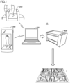
- Fig. 1 is a schematic view showing a configuration example of a cutting system 10 according to the first embodiment.
- the cutting system 10 includes a cutting support apparatus 100, a measuring apparatus 200 that measures a foot shape, and a cutting apparatus 400 that cuts a wooden board based on a cutting pattern.
- the cutting system 10 shown in Fig. 1 includes the measuring apparatus 200, the cutting system 10 may use pre-stored shoe last data without including the measuring apparatus 200.
- the foot shape may be measured using a mobile terminal 300 such as a smartphone, instead of the measuring apparatus 200.
- the cutting support apparatus 100 can communicate with a not-shown data server placed inside or outside a store.
- the cutting support apparatus 100 generates shoe last data based on foot shape data obtained from the measuring apparatus 200 or the mobile terminal 300, and further, generates a cutting pattern of a plurality of plate-like parts based on the shoe last data. When shoe last data stored in advance is used, the cutting support apparatus 100 may generate only a cutting pattern without generating shoe last data.
- Fig. 2 is a schematic view showing a hardware configuration example of the cutting support apparatus 100 according to the first embodiment. Referring to Fig. 2 , the cutting support apparatus 100 includes a processor 102, a main memory 104, an input unit 106, an output unit 108, a storage 110, an optical drive 112, and a communication controller 120. These components are connected through a processor bus 118.
- the processor 102 is implemented by a CPU, a GPU or the like, and can read programs (by way of example, an OS 1102 and a shoe last program 1104) stored in the storage 110 and deploy the programs in the main memory 104 for execution.
- the processor 102 executes various programs read from the storage 110.
- the shoe last program 1104 computes the shoe last data from the foot shape data and additional information received by the input unit 106, based on a prescribed algorithm.
- a cutting program 1106 uses a prescribed algorithm, generates the cutting pattern of the plurality of plate-like parts based on the shoe last data.
- the cutting program 1106 includes an algorithm for applying a bounding box to each of individual plate-like parts and laying the plurality of plate-like parts over the wooden board in accordance with an arrangement condition.
- the processor 102 that executes the programs corresponds to a computing unit of the cutting support apparatus 100.
- the main memory 104 is implemented by, for example, a volatile storage device such as a DRAM or an SRAM
- the storage 110 is implemented by, for example, a non-volatile storage device such as an HDD or an SSD.
- the shoe last program 1104 and the cutting program 1106 for providing a function as the cutting support apparatus 100 are stored in the storage 110.
- Information on a shape and a type of the plurality of plate-like parts and an order of assembly of the plurality of plate-like parts is further stored in the storage 110.
- the input unit 106 includes an input interface connected to the measuring apparatus 200 or the mobile terminal 300 to receive the foot shape data from the measuring apparatus 200 or the mobile terminal 300.
- the input unit 106 is implemented by a keyboard, a mouse, a microphone, a touch device or the like, and can further receive the information selected by the user.
- the output unit 108 includes an output interface that outputs the cutting pattern of the plurality of plate-like parts calculated by the processor 102 to the cutting apparatus 400.
- the output unit 108 is implemented by a display, various indicators, a printer or the like, and outputs a processing result or the like from the processor 102.
- the communication controller 120 exchanges data with another control device or the like by using wired or wireless communication.
- the cutting support apparatus 100 may exchange the foot shape data and the additional information with the measuring apparatus 200 or the mobile terminal 300 through the communication controller 120, and may exchange the cutting pattern with the cutting apparatus 400 through the communication controller 120.
- a USB controller connected to the processor bus 118 may be provided to exchange the data with another control device or the like through USB connection.
- the cutting support apparatus 100 includes the optical drive 112 that may read a computer-readable program stored in a recording medium 114 (e.g., optical recording medium such as a digital versatile disc (DVD)) in a non-transitory manner, and install the program in the storage 110 or the like.
- a recording medium 114 e.g., optical recording medium such as a digital versatile disc (DVD)
- DVD digital versatile disc
- the cutting program 1106 and the like executed in the cutting support apparatus 100 may be installed through the computer-readable recording medium 114, the cutting program 1106 and the like may be installed by being downloaded from a server device or the like on a network.
- the functions provided by the cutting support apparatus 100 according to the embodiment may be implemented by using a part of a module provided by the OS.
- FIG. 2 shows the configuration example in which the processor 102 executes the programs to thereby provide the functions required as the cutting support apparatus 100
- a part or all of these provided functions may be implemented by using a dedicated hardware circuit (such as, for example, an ASIC or an FPGA).
- a dedicated hardware circuit such as, for example, an ASIC or an FPGA.
- the configuration of the cutting support apparatus 100 shown in Fig. 2 is illustrative and the present disclosure is not limited to this configuration.
- the measuring apparatus 200 is implemented by a three-dimensional foot shape scanner using laser measurement.
- a laser measurement apparatus that is built into walls provided on both sides of a foot put on a top board measures the foot while moving from a toe to a heel of the foot, thereby obtaining three-dimensional foot shape data of the user.
- a measurement method or the like of the measuring apparatus 200 is not particularly limited, as long as it can measure the three-dimensional foot shape data.
- the mobile terminal 300 such as a smartphone may also be used to capture an image of the foot of the user and obtain image data of the foot, and the foot shape data may be generated from the obtained image data of the foot through preliminarily installed software.
- the cutting apparatus 400 is, for example, an apparatus that cuts a plurality of plate-like parts from a plate-like wooden board with laser beams based on a cutting pattern.
- the cutting apparatus 400 outputs a wooden board 3 in which a plurality of plate-like parts are cut based on the cutting pattern.
- a method of cutting is not limited to laser beams, and the plate-like wooden board may be cut with a metal blade or a water pressure.
- Fig. 3 is a perspective view of the shoe last 2 according to the first embodiment.
- the shoe last 2 shown in Fig. 3 is made by assembling a plurality of plate-like parts cut from a wooden board.
- An engagement groove is provided in each of the plate-like parts and the shoe last 2 can be assembled by attaching each plate-like part to the engagement groove.
- the shoe last 2 for one foot can be made of two wooden boards each having a size of 300 mm ⁇ 450 mm. Forty-one plate-like parts are cut from the two wooden boards.
- the cutting support apparatus 100 generates a cutting pattern generally by laying forty-one plate-like parts over the wooden board for cutting forty-one plate-like parts from the two wooden boards with material loss being reduced.
- the cutting pattern When the cutting pattern is unconditionally generated, however, the cutting pattern in which the plate-like parts are arranged irrespectively of positions thereof in the shoe last 2 is generated.
- the plurality of plate-like parts are cut based on this cutting pattern, assembly of the shoe last 2 from the plurality of cut plate-like parts becomes difficult.
- the cutting support apparatus 100 should create the cutting pattern in consideration of ease in assembly.
- the size of the wooden board and the number of plate-like parts are by way of example, and limitation to those values is not intended.
- the cutting support apparatus 100 divides an area of plate-like parts to be arranged in a wooden board into a plurality of areas in accordance with a type of the plate-like parts that form the shoe last 2, and determines positions of the plurality of plate-like parts to be arranged in each of the areas and generates a cutting pattern.
- the plate-like parts that form the shoe last 2 can broadly be divided into such types as a "toe part,” an “instep part,” an “ankle part,” a “malleolus part,” a “foot length part,” a “heel height part,” and a “circumferential heel part.”
- the division above is by way of example, and the "toe part,” the “instep part,” and the “ankle part” may collectively be defined as a "foot width direction part,” and the "malleolus part” may be divided into a "medial malleolus part” and a "lateral malleolus part.”
- the cutting support apparatus 100 thus generates a cutting pattern with an area being divided into areas in accordance with the type of the plate-like parts, so that a plurality of plate-like parts are cut collectively for each type of the plate-like parts in cutting of the wooden board based on the cutting pattern. Since a plurality of plate-like parts close in position to each other in the shoe last 2 are collectively cut, assembly of the shoe last 2 is facilitated.
- a cutting pattern generated by the cutting support apparatus 100 will be described. Initially, the cutting support apparatus 100 allocates an area where the "toe part,” the “instep part,” the “ankle part,” and the “malleolus part” are to be arranged to a first cutting pattern.
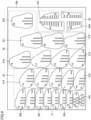
- Fig. 4 is a plan view of a first cutting pattern 30a according to the first embodiment. In the cutting pattern 30a shown in Fig. 4 , from the left in the figure, an area 31 for the "toe part,” an area 32 for the "instep part,” an area 33 for the "ankle part,” and an area 34 for the "malleolus part” are allocated in this order.
- the cutting support apparatus 100 determines positions of the plurality of plate-like parts in each area based on an arrangement condition.
- the arrangement condition includes a condition of alignment of the plurality of plate-like parts in the order of assembly and a condition of minimization of an area of each area where the plurality of plate-like parts are arranged.
- the arrangement condition is not limited to the condition above.
- any one of the condition of alignment of the plurality of plate-like parts in the order of assembly and the condition of minimization of the area of each area where the plurality of plate-like parts are arranged may be applicable, or an another condition may further be added.
- a condition of minimization of a time period for cutting a plurality of plate-like parts to be arranged in each area or a condition that orientations of a plurality of plate-like parts to be arranged in each area are identical may be added.
- the cutting support apparatus 100 when the condition of minimization of the time period for cutting is added, the cutting support apparatus 100 generates a cutting pattern where a plurality of plate-like parts are arranged to reduce a distance of movement of a cutting portion (a portion from which laser beams are emitted) of the cutting apparatus 400 that cuts a wooden board.
- the order from a toe side is adopted as the condition of alignment of the plurality of plate-like parts in the order of assembly. Therefore, as shown in Fig. 4 , plate-like parts (toe parts) within the area 31 are laid in the order from the toe side from a position on a lower side of the figure. Similarly, plate-like parts (instep parts) within the area 32 are laid in the order from the toe side subsequently to the area 31, and plate-like parts (ankle parts) within the area 33 are laid in the order from the toe side subsequently to the area 32.
- Plate-like parts as the "foot width direction parts” including the “toe parts,” the “instep parts,” and the “ankle parts” are provided with serial numbers from 1 to 22 as identification information.
- Fig. 4 shows a plate-like part 201 as a first plate-like part and a plate-like part 204 as a fourth plate-like part. Though reference characters are not provided to all plate-like parts in Fig. 4 for avoiding complexity of the figure, an nth plate-like part is assumed to be labeled as a plate-like part 2n.
- Plate-like parts (malleolus parts) within the area 34 are laid in the order from the toe side from a position on an upper side in the figure.
- the plate-like parts as the "malleolus parts” are provided with serial numbers from S1 to S4 as identification information.
- the plate-like parts S1 and S2 are plate-like parts as the "lateral malleolus parts” and the plate-like parts S3 and S4 are plate-like parts as the "medial malleolus parts.”
- Fig. 4 shows a plate-like part 2S1 as an S 1st plate-like part and a plate-like part 2S2 as an S2nd plate-like part. Though reference characters are not provided to all plate-like parts in Fig. 4 for avoiding complexity of the figure, an Sn-th plate-like part is assumed to be labeled as a plate-like part 2Sn.
- Figs. 5A and 5B are each a diagram showing a position in the shoe last 2, of a plate-like part arranged in the cutting pattern 30a shown in Fig. 4 .
- Fig. 5A shows positions in the shoe last 2, of the plate-like parts as the "foot width direction parts" including the “toe parts,” the “instep parts,” and the “ankle parts,” with those plate-like parts being hatched.
- the "foot width direction parts” from the first plate-like part 201 to the twenty-second plate-like parts 222 are hatched.
- Fig. 5B shows positions in the shoe last 2, of the plate-like parts as the "malleolus parts," with those plate-like parts being hatched. Specifically, the "malleolus parts" from the Slst plate-like part 2S1 to an S4th plate-like part 2S4 are hatched. Fig. 5B shows only the Slst plate-like part 2S1 and the S2nd plate-like part 2S2 as the plate-like parts.
- Fig. 6 is a plan view of a second cutting pattern 30b according to the first embodiment.
- an area 35 for the "foot length parts,” an area 36 for the "heel height parts,” and an area 37 for the "circumferential heel parts” are allocated in this order.
- the cutting support apparatus 100 determines positions of the plurality of plate-like parts in each area based on an arrangement condition. For example, when the order of assembly of the plate-like parts as the "foot length parts" is set to the order from an outer side, as shown in Fig. 6 , the plate-like parts (foot length parts) within the area 35 are laid in the order from the outer side from a position on the left in the figure. When the order of assembly of the plate-like parts as the "heel height parts” is set to the order from an ankle side, as shown in Fig. 6 , the plate-like parts (heel height parts) within the area 36 are laid in the order from the ankle side from a position on a lower side in the figure.
- the plate-like parts as the "foot length parts” are provided with serial numbers from N1 to N3 as the identification information.
- Fig. 6 shows a plate-like part 2N1 as an N1st plate-like part, a plate-like part 2N2 as an N2nd plate-like part, and a plate-like part 2N3 as an N3rd plate-like part.
- the plate-like parts as the "heel height parts” are provided with signs A to H as the identification information.
- Fig. 6 shows a plate-like part 2A as the plate-like part with the sign A and shows a plate-like part 2H as the plate-like part with the sign H.
- the plate-like parts as the "circumferential heel parts” are provided with signs a to d as the identification information.
- Fig. 6 shows a plate-like part 2c as the plate-like part with the sign c and shows a plate-like part 2d as the plate-like part with the sign d.
- reference characters are not provided to all plate-like parts in Fig. 6 for avoiding complexity of the figure, a plate-like part with a sign is assumed to be labeled as a plate-like part 2 + sign.
- Figs. 7A and 7B each show a position in the shoe last 2, of a plate-like part arranged in the cutting pattern 30b shown in Fig. 6 .
- Fig. 7A shows positions in the shoe last 2, of the plate-like parts as the "foot length parts," with those plate-like parts being hatched. Specifically, the "foot length parts" from the N1st plate-like part 2N1 to the N3rd plate-like part 2N3 are hatched.
- Fig. 7B shows positions in the shoe last 2, of the plate-like parts as the "heel height parts” and the “circumferential heel parts,” with those plate-like parts being hatched. Specifically, the "heel height parts” from the plate-like part 2A with the sign A to the plate-like part 2H with the sign H are hatched, and the “circumferential heel parts” from the plate-like part 2a with the sign a to the plate-like part 2d with the sign d are hatched. Fig. 7B does not show the plate-like part 2a with the sign a.
- the identification information shown in Figs. 4 and 6 is outputted to the cutting apparatus 400 as a part of the cutting pattern.
- the cutting apparatus 400 writes the identification information included in the cutting pattern into a surface of the wooden board with laser beams.
- the cutting support apparatus 100 provides the identification information to each of the plurality of plate-like parts based on the order of assembly thereof as above. Rather than providing plate-like parts with a different type of identification information for each area as above, identification information of the same type (for example, first to forty-first) may be provided to plate-like parts throughout all areas.
- the cutting support apparatus 100 may provide a plurality of plate-like parts with the identification information such that orientations of the identification information are identical after assembly of the plurality of plate-like parts.
- the identification information in the same orientation is provided, like serial numbers from 1 to 22 provided to the plate-like parts as the "foot width direction parts" shown in Fig. 4 .
- the identification information is thus readily visually recognized also after assembly of a plurality of plate-like parts.
- Fig. 8 is a flowchart for illustrating a method of creating a cutting pattern of a plate-like part in the cutting support apparatus 100 according to the embodiment.
- the cutting support apparatus 100 receives shoe last data computed from foot shape data obtained by measurement by the measuring apparatus 200 or the mobile terminal 300 (step S11).
- the cutting support apparatus 100 receives shoe last data computed from the foot shape data obtained by measurement.
- the cutting support apparatus 100 may receive existing shoe last data.
- the cutting support apparatus 100 divides an area of plate-like parts to be arranged in the wooden board in accordance with the type of the plate-like parts (step S12). As shown in Figs. 4 and 6 , the cutting support apparatus 100 divides the two wooden boards into areas for each of such types as the "toe parts,” the “instep parts,” the “ankle parts,” the “malleolus parts,” the “foot length parts,” the “heel height parts,” and the circumferential heel parts.”
- the cutting support apparatus 100 determines a position of the area for each type based on the arrangement condition (step S13).
- a condition the same as the condition for arrangement of the plate-like part is allocated as the condition for arrangement of the area.
- the condition for arrangement of the area may naturally be different from the condition for arrangement of the plate-like part.
- the arrangement condition includes the condition of alignment of the plurality of areas in the order of assembly and the condition of minimization of an area of the plurality of areas arranged on the wooden board.
- the cutting support apparatus 100 aligns the plurality of areas in the order of assembly, it determines positions of the plurality of areas to minimize the area thereof on the wooden board.
- the arrangement condition is not limited to the condition above. Any one of the condition of alignment of the plurality of areas in the order of assembly and the condition of minimization of the area of the plurality of areas arranged on the wooden board may be applicable, or yet another condition may be added.
- Figs. 9A and 9B are each a plan view of a cutting pattern according to a modification of the first embodiment.
- Fig. 9A is a plan view of a first cutting pattern 30c in the modification and
- Fig. 9B is a plan view of a second cutting pattern 30d in the modification.
- the area 35 for the "foot length parts,” the area 31 for the “toe parts,” and the area 32 for the “instep parts” are allocated in this order.
- the area 36 for the "heel height parts,” the area 37 for the “circumferential heel parts,” the area 33 for the "ankle parts,” and the area 34 for the "malleolus parts” are allocated in this order.
- the "foot length parts” in the first cutting pattern 30c as shown in Figs. 9A and 9B can be cut first and the “toe parts” and the “instep parts” can sequentially be inserted into the "foot length parts” so that the user can efficiently do works.
- the cutting support apparatus 100 determines positions of the plurality of plate-like parts included in each area, a position on the wooden board of which has been determined, based on the arrangement condition (step S14). For example, in the area of the "toe parts" shown in Fig. 4 , the cutting support apparatus 100 determines positions of individual plate-like parts by aligning seven plate-like parts in the order from the toe side to minimize the area of that area.
- the shape and the size of the plurality of plate-like parts are different depending on a size of a shoe.
- the shape and the size of a plurality of plate-like parts created based on shoe last data of a shoe having a foot length size of 30 cm is larger than the shape and the size of a plurality of plate-like parts created based on shoe last data of a shoe having a foot length size of 25 cm.
- all plate-like parts created based on the shoe last data of the shoe having the foot length size of 25 cm are accommodated in two wooden boards. All plate-like parts created based on the shoe last data of the shoe having the foot length size of 30 cm, however, may not be accommodated in two wooden boards.
- the cutting support apparatus 100 determines whether or not the cutting pattern is accommodated in two wooden boards (step S15).
- the cutting support apparatus 100 When the cutting pattern is accommodated in the two wooden boards (YES in step S15), the cutting support apparatus 100 outputs the cutting pattern to the cutting apparatus 400 (step S16).
- the cutting apparatus 400 cuts the wooden board based on the cutting pattern provided from the cutting support apparatus 100 as shown in Figs. 4 and 6 .
- the cutting support apparatus 100 reduces the number of plate-like parts that form the shoe last (step S17). For example, when the shoe last is constituted of forty-one plate-like parts, the cutting support apparatus 100 reduces the number of plate-like parts to forty and changes the cutting pattern to accommodate the cutting pattern of the plurality of plate-like parts in two wooden boards.
- the cutting support apparatus 100 reduces a plate-like part that has less effect on the shape of the shoe last among the plurality of plate-like parts and generates the cutting pattern.
- the plate-like part that has less effect on the shape of the shoe last is, for example, a plate-like part small in difference in shape and size from an adjacent plate-like part.
- the cutting support apparatus 100 determines that a plate-like part in a portion less in change in shape in the shoe last falls under the plate-like part that has less effect on the shape of the shoe last.
- the cutting support apparatus 100 reduces the fourth plate-like part 204 among the seven plate-like parts as the "toe parts" so that the "toe parts" are composed of six plate-like parts.
- step S17 When the cutting support apparatus 100 reduces the number of plate-like parts in step S17, the process returns to step S14 and the cutting support apparatus 100 determines again positions of the plurality of plate-like parts for each area based on the arrangement condition.
- the cutting support apparatus 100 determines whether or not the cutting pattern is accommodated in two wooden boards, the number of wooden boards is different depending on a size of the wooden board. For example, the cutting pattern would be accommodated in a single wooden board if the wooden board has a size larger than 300 mm ⁇ 450 mm, and three or more wooden boards would be required if a wooden board has a size smaller than that size. Depending on a size of the shoe last, the cutting pattern may be accommodated in a single wooden board having the same size of 300 mm ⁇ 450 mm. Therefore, in the description above, the cutting support apparatus 100 determines whether or not the cutting pattern is accommodated, for example, based on such setting that two wooden boards each having a size of 300 mm ⁇ 450 mm are adopted as the prescribed member.
- the cutting support apparatus 100 may provide a cutting pattern with a two-dimensional code other than a number, as the identification information of a plurality of plate-like parts. By providing a two-dimensional code to each of plate-like parts, making of a shoe last can more positively be supported.
- the cutting apparatus 400 writes a two-dimensional code included in a cutting pattern into a surface of the wooden board with laser beams.
- a method of supporting assembly of a plurality of plate-like parts for example, in making of a shoe last by a user from the plurality of plate-like parts obtained by cutting a wooden board based on a cutting pattern at a store will be described.
- a person who makes a shoe last is naturally not limited to the user but a salesperson may make the shoe last.
- the support is not limited to use in making of a shoe last of a custom-made shoe but may be used in a factory where shoe lasts for ready-made shoes are made.
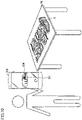
- Fig. 10 is a diagram showing overview of assembly support with the use of a cutting pattern according to the second embodiment.
- each of plate-like parts is assumed as being provided with a two-dimensional code Q1 in the cutting pattern shown in Figs. 4 and 6 .
- the two-dimensional code Q1 is naturally not limited to being provided to each plate-like part, but may be provided to any one plate-like part or a margin of a wooden board.
- a user captures an image of one of a plurality of plate-like parts placed on a workbench 50 with a camera (an image pick-up unit) contained in the mobile terminal 300 as shown in Fig. 10 . Since the two-dimensional code Q1 has been provided to the plate-like part the image of which was captured, the mobile terminal 300 reads a URL of a shoe last assembly support site prepared in advance in a server or the like with the use of the two-dimensional code Q1.
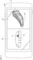
- Fig. 11 is a diagram showing exemplary representation shown on a display unit in assembly support according to the second embodiment.
- a screen 40 is displayed on a display (display unit) of the mobile terminal 300.
- the screen 40 includes a screen 40a for the plate-like part 204 the image of which was picked up and a screen 40b showing a three-dimensional view of the completed shoe last 2.
- the screen 40a provides representation, for example, showing that the plate-like part the image of which was picked up is the plate-like part 204 fourth from the toe side.
- the screen 40b shows representation emphasizing a position of attachment of the plate-like part fourth from the toe side in the completed shoe last 2.
- the position of attachment of the plate-like part 204 the image of which was picked up can be emphasized by showing the plate-like part at the position of attachment in a color or with a line type different from that of other plate-like parts or by showing the plate-like part as blinking in a three-dimensional view of the completed shoe last 2.
- a screen such as a monitor of a PC rather than the mobile terminal 300 may be applicable.
- Support information for making a shoe last may be shown on a virtual reality (VR) goggle that shows virtual reality, an augmented reality (AR) goggle that shows augmented reality, or a mixed reality (MR) goggle that can show virtual reality and augmented reality.
- VR virtual reality
- AR augmented reality
- MR mixed reality
- the identification information provided to a plate-like part is not the two-dimensional code Q1 but a number alone
- similar support information is obtained also by access to a shoe last assembly support site by a user and entry of the number provided to the plate-like part.
- the user may naturally freely do assembly based on the number or the identification information provided to the plate-like part without accessing the support site, or an assembly manual based on the number or the identification information provided to the plate-like part may be prepared.
- the cutting support apparatus 100 is a cutting support apparatus that generates a cutting pattern for cutting a plurality of plate-like parts that form a shoe last from a plate-like member.
- the cutting support apparatus 100 includes an input unit 106 that receives shoe last data, a storage 110 in which a shape and a type of the plurality of plate-like parts are stored, a processor 102 that generates the cutting pattern for cutting the plurality of plate-like parts from the plate-like member having a predetermined size based on the shoe last data received by the input unit 106 and the shape of the plurality of plate-like parts stored in the storage 110, and an output unit 108 that outputs the cutting pattern computed by the processor 102.
- the processor 102 divides an area of plate-like parts to be arranged in the plate-like member into a plurality of areas in accordance with the type of the plate-like parts that form the shoe last, and determines positions of the plurality of plate-like parts to be arranged in each of the areas based on an arrangement condition and generates the cutting pattern.
- the cutting support apparatus 100 can generate a cutting pattern suitable for making of a shoe last by cutting a plurality of plate-like parts from a plate-like member and assembling the plurality of plate-like parts.
- the processor 102 may determine a position of each of the areas in the plate-like member based on the arrangement condition.
- the cutting support apparatus 100 can thus appropriately support a position of each area.
- An order of assembly of the plurality of plate-like parts may further be stored in the storage 110, and the arrangement condition may include at least one of a condition of alignment of the plurality of plate-like parts in the order of assembly and a condition of minimization of an area of each of the areas where the plurality of plate-like parts are arranged.
- the cutting support apparatus 100 can thus generate the cutting pattern in consideration of at least one of minimization of the area of the area and the order of assembly.
- the order of assembly of the plurality of plate-like parts may be performed in an order from a toe side.
- the cutting support apparatuses 100 can thus generate the cutting pattern in consideration of the order in assembly in the order from the toe side.
- the arrangement condition may further include a condition of minimization of a time period for cutting the plurality of plate-like parts to be arranged in each of the areas.
- This cutting support apparatus 100 can thus generate the cutting pattern that achieves a shorter time period for making a shoe last.
- the arrangement condition may further include a condition that orientations of the plurality of plate-like parts to be arranged in each of the areas are identical.
- the cutting support apparatus 100 can thus facilitate recognition by the user of the type of the cut plate-like part to thereby facilitate assembly.
- the processor 102 may generate the cutting pattern in which the plurality of plate-like parts are arranged, as being distributed among a plurality of plate-like members.
- the cutting pattern may be generated as being distributed among a plurality of plate-like members.
- the processor 102 may generate the cutting pattern with the number of plate-like parts to be arranged in the plate-like members being reduced from the plurality of plate-like parts.
- the cutting support apparatus 100 can thus generate a cutting pattern with less material loss in cutting of a plurality of plate-like parts from a plate-like member.
- the processor 102 may generate the cutting pattern, with a plate-like part that has less effect on the shape of the shoe last among the plurality of plate-like parts being reduced.
- the cutting support apparatus 100 can thus generate a cutting pattern with less material loss in cutting of a plurality of plate-like parts from a plate-like member without accuracy of the shoe last being effected.
- the processor 102 may generate the cutting pattern in which identification information is provided to each of the plurality of plate-like parts.
- the cutting support apparatus 100 can thus generate a cutting pattern suitable for making of a shoe last by assembling a plurality of plate-like parts.
- the processor 102 may provide the identification information to the cutting pattern such that orientations of the identification information are identical after the plurality of plate-like parts are assembled.
- the cutting support apparatus 100 can thus generate a cutting pattern that facilitates recognition by a user of identification information in making a shoe last by assembling a plurality of plate-like parts.
- a cutting system 10 is a system that generates a cutting pattern for cutting a plurality of plate-like parts that form a shoe last from a plate-like member and cuts the plurality of plate-like parts from the plate-like member based on the generated cutting pattern.
- the cutting system 10 includes a cutting support apparatus 100 that generates the cutting pattern and a cutting apparatus 400 that cuts the plurality of plate-like parts from the plate-like member based on the cutting pattern computed by the cutting support apparatus 100.
- the cutting system 10 can thus generate a cutting pattern suitable for making of a shoe last by cutting a plurality of plate-like parts from a plate-like member and assembling the plurality of plate-like parts.
- a cutting pattern generation method is a method of generating a cutting pattern for cutting a plurality of plate-like parts that form a shoe last from a plate-like member.
- the cutting pattern generation method includes receiving shoe last data, generating the cutting pattern for cutting the plurality of plate-like parts from the plate-like member having a predetermined size based on the received shoe last data and a shape of the plurality of plate-like parts stored in a storage 110, and outputting the computed cutting pattern.
- the generating the cutting pattern includes dividing an area of plate-like parts to be arranged in the plate-like member into a plurality of areas in accordance with a type of the plate-like parts that form the shoe last and determining positions of the plurality of plate-like parts to be arranged in each of the areas based on an arrangement condition.
- Data in the storage 110 may be stored in a data server at a store, a data server arranged at a manufacturer different from the store, or a data server at another location.
- the data server may be implemented in a form of a cloud service.
- the shoe last described above is by way of example and not limited thereto.
- a hybrid shoe last having a toe portion composed of a plurality of plate-like parts and having a partial region such as a portion from a midfoot portion to a heel portion composed of solid parts made of a thermoplastic resin may be applicable.
Landscapes
- Engineering & Computer Science (AREA)
- Physics & Mathematics (AREA)
- General Physics & Mathematics (AREA)
- Life Sciences & Earth Sciences (AREA)
- Mechanical Engineering (AREA)
- Geometry (AREA)
- Forests & Forestry (AREA)
- Human Computer Interaction (AREA)
- Manufacturing & Machinery (AREA)
- Automation & Control Theory (AREA)
- Theoretical Computer Science (AREA)
- Mathematical Analysis (AREA)
- Pure & Applied Mathematics (AREA)
- Computer Hardware Design (AREA)
- Evolutionary Computation (AREA)
- General Engineering & Computer Science (AREA)
- Mathematical Optimization (AREA)
- Computational Mathematics (AREA)
- Biophysics (AREA)
- Footwear And Its Accessory, Manufacturing Method And Apparatuses (AREA)
- Management, Administration, Business Operations System, And Electronic Commerce (AREA)
Abstract
Description
- This nonprovisional application is based on
Japanese Patent Application No. 2021-149535 filed with the Japan Patent Office on September 14, 2021 - The present disclosure relates to a cutting support apparatus, a cutting pattern generation method, and a cutting system.
- When manufacturing a custom-made shoe tailored to a foot of a user, a shoe last should be made in conformity with a foot shape measured with a measuring apparatus.
US Patent Publication No. 2018/0014609 discloses manufacturing of footwear within a portable housing.US Patent Publication No. 2016/0206049 discloses a last pre-form that can be reformed with the use of a shape memory polymer.Chinese Patent No. 109732913 discloses formation of a shoe last by 3D printing. - In each patent literature, however, for making a shoe last dedicated for a user, a dedicated large machine has been used and time and costs have been required. In addition, in each patent literature, it has been difficult to have a user experience making of a shoe last. In order to have the user experience making of a shoe last, for example, the shoe last should be made by assembling a plurality of plate-like parts at a store or the like. In order to make a shoe last by assembling a plurality of plate-like parts at a store or the like, the plurality of plate-like parts should be prepared for facilitating assembly by the user.
- The present disclosure provides a cutting support apparatus, a cutting pattern generation method, and a cutting system for generating a cutting pattern for cutting a plurality of plate-like parts from a plate-like member in making of a shoe last by assembling the plurality of plate-like parts.
- A cutting support apparatus according to one aspect of the present disclosure generates a cutting pattern for cutting a plurality of plate-like parts that form a shoe last from a plate-like member. The cutting support apparatus includes an input unit that receives shoe last data, a storage unit in which a shape and a type of the plurality of plate-like parts are stored, a computing unit that generates the cutting pattern for cutting the plurality of plate-like parts from the plate-like member having a predetermined size based on the shoe last data received by the input unit and the shape of the plurality of plate-like parts stored in the storage unit, and an output unit that outputs the cutting pattern computed by the computing unit. The computing unit divides an area of plate-like parts to be arranged in the plate-like member into a plurality of areas in accordance with the type of the plate-like parts that form the shoe last, and determines positions of the plurality of plate-like parts to be arranged in each of the areas based on an arrangement condition and generates the cutting pattern.
- A cutting system according to one aspect of the present disclosure generates a cutting pattern for cutting a plurality of plate-like parts that form a shoe last from a plate-like member and cuts the plurality of plate-like parts from the plate-like member based on the generated cutting pattern. The cutting system includes an input apparatus that receives shoe last data, a storage apparatus in which a shape and a type of the plurality of plate-like parts are stored, a computing apparatus that generates the cutting pattern for cutting the plurality of plate-like parts from the plate-like member having a predetermined size based on the shoe last data received by the input apparatus and the shape of the plurality of plate-like parts stored in the storage apparatus, and a cutting apparatus that cuts the plurality of plate-like parts from the plate-like member based on the cutting pattern computed by the computing apparatus. The computing apparatus divides an area of plate-like parts to be arranged in the plate-like member into a plurality of areas in accordance with the type of the plate-like parts that form the shoe last, and determines positions of the plurality of plate-like parts to be arranged in each of the areas based on an arrangement condition and generates the cutting pattern.
- A cutting pattern generation method according to one aspect of the present disclosure is a method of generating a cutting pattern for cutting a plurality of plate-like parts that form a shoe last from a plate-like member. The cutting pattern generation method includes receiving shoe last data, generating the cutting pattern for cutting the plurality of plate-like parts from the plate-like member having a predetermined size based on the received shoe last data and a shape of the plurality of plate-like parts stored in a storage unit, and outputting the computed cutting pattern. The generating the cutting pattern includes dividing an area of plate-like parts to be arranged in the plate-like member into a plurality of areas in accordance with a type of the plate-like parts that form the shoe last and determining positions of the plurality of plate-like parts to be arranged in each of the areas based on an arrangement condition.
- The foregoing and other objects, features, aspects and advantages of the present invention will become more apparent from the following detailed description of the present invention when taken in conjunction with the accompanying drawings.
-
-
Fig. 1 is a schematic view showing a configuration example of a cutting system according to a first embodiment. -
Fig. 2 is a schematic view showing a hardware configuration example of a cutting support apparatus according to the first embodiment. -
Fig. 3 is a perspective view of a shoe last according to the first embodiment. -
Fig. 4 is a plan view of a first cutting pattern according to the first embodiment. -
Figs. 5A and 5B are each a diagram showing a position in a shoe last, of a plate-like part arranged in the cutting pattern shown inFig. 4 . -
Fig. 6 is a plan view of a second cutting pattern according to the first embodiment. -
Figs. 7A and 7B are each a diagram showing a position in the shoe last, of a plate-like part arranged in the cutting pattern shown inFig. 6 . -
Fig. 8 is a flowchart for illustrating a method of creating a cutting pattern of plate-like parts in the cutting support apparatus according to the first embodiment. -
Figs. 9A and 9B are each a plan view of a cutting pattern according to a modification of the first embodiment. -
Fig. 10 is a diagram showing overview of assembly support with the use of a cutting pattern according to a second embodiment. -
Fig. 11 is a diagram showing exemplary representation shown on a display unit in assembly support according to the second embodiment. - An embodiment will be described below with reference to the drawings. In the description below, the same elements have the same reference characters allotted and their labels and functions are also the same. Therefore, detailed description thereof will not be repeated.
- In a first embodiment, an example of application of the present invention will be described. When manufacturing a custom-made shoe tailored to a foot of a user at, for example, a store, a shoe last should be made based on shoe last data generated based on foot shape data obtained by measuring a foot shape using a measuring apparatus. In particular, in making a shoe last at a store, for such reasons as restriction on facilities and an experience of making of a shoe last by a user, a method of making a shoe last by assembling a plurality of plate-like parts has been adopted. Therefore, a plurality of plate-like parts should be cut from a wooden board such as a medium-density fiberboard (MDF).
- In the first embodiment, a cutting support apparatus generates a cutting pattern for cutting a plurality of plate-like parts from a wooden board. Thereafter, in the first embodiment, a cutting apparatus cuts a plurality of plate-like parts from the wooden board based on the cutting pattern generated by the cutting support apparatus. In the first embodiment, a cutting system that performs such a series of processing and makes a plurality of plate-like parts necessary for making a shoe last will be described.
- In the first embodiment, an engagement groove is provided in each of a plurality of plate-like parts and a shoe last can be made by attaching each plate-like part to the engagement groove. A wooden board will be described below as an exemplary plate-like member from which a plurality of plate-like parts are cut. The wooden board is not limited to the MDF but another wooden board such as an insulation fiberboard (IB) or a hard fiberboard (HB) may be applicable. Among IBs, an A-class insulation board, a tatami board, or a sheathing board may be employed as a material for a plate-like part. Among HBs, a standard hardboard or a tempered hardboard may be employed as a material for a plate-like part. The material for the plate-like part is not limited to the wooden board as described above, and a highly recyclable corrugated cardboard or a material suitable for a plate-like part such as a cork, a metal, or a thermoplastic resin may be applicable.
-
Fig. 1 is a schematic view showing a configuration example of acutting system 10 according to the first embodiment. Referring toFig. 1 , thecutting system 10 includes acutting support apparatus 100, ameasuring apparatus 200 that measures a foot shape, and acutting apparatus 400 that cuts a wooden board based on a cutting pattern. Although thecutting system 10 shown inFig. 1 includes themeasuring apparatus 200, thecutting system 10 may use pre-stored shoe last data without including themeasuring apparatus 200. In addition, depending on stores, or at a remote location such as a user's house, the foot shape may be measured using amobile terminal 300 such as a smartphone, instead of themeasuring apparatus 200. Furthermore, thecutting support apparatus 100 can communicate with a not-shown data server placed inside or outside a store. - The
cutting support apparatus 100 generates shoe last data based on foot shape data obtained from themeasuring apparatus 200 or themobile terminal 300, and further, generates a cutting pattern of a plurality of plate-like parts based on the shoe last data. When shoe last data stored in advance is used, thecutting support apparatus 100 may generate only a cutting pattern without generating shoe last data.Fig. 2 is a schematic view showing a hardware configuration example of thecutting support apparatus 100 according to the first embodiment. Referring toFig. 2 , the cuttingsupport apparatus 100 includes aprocessor 102, amain memory 104, aninput unit 106, anoutput unit 108, astorage 110, anoptical drive 112, and acommunication controller 120. These components are connected through aprocessor bus 118. - The
processor 102 is implemented by a CPU, a GPU or the like, and can read programs (by way of example, anOS 1102 and a shoe last program 1104) stored in thestorage 110 and deploy the programs in themain memory 104 for execution. Theprocessor 102 executes various programs read from thestorage 110. Specifically, the shoelast program 1104 computes the shoe last data from the foot shape data and additional information received by theinput unit 106, based on a prescribed algorithm. Using a prescribed algorithm, acutting program 1106 generates the cutting pattern of the plurality of plate-like parts based on the shoe last data. For example, thecutting program 1106 includes an algorithm for applying a bounding box to each of individual plate-like parts and laying the plurality of plate-like parts over the wooden board in accordance with an arrangement condition. Theprocessor 102 that executes the programs corresponds to a computing unit of the cuttingsupport apparatus 100. - The
main memory 104 is implemented by, for example, a volatile storage device such as a DRAM or an SRAM Thestorage 110 is implemented by, for example, a non-volatile storage device such as an HDD or an SSD. - In addition to the
OS 1102 for implementing a basic function, the shoelast program 1104 and thecutting program 1106 for providing a function as the cuttingsupport apparatus 100 are stored in thestorage 110. Information on a shape and a type of the plurality of plate-like parts and an order of assembly of the plurality of plate-like parts is further stored in thestorage 110. - The
input unit 106 includes an input interface connected to the measuringapparatus 200 or themobile terminal 300 to receive the foot shape data from the measuringapparatus 200 or themobile terminal 300. Theinput unit 106 is implemented by a keyboard, a mouse, a microphone, a touch device or the like, and can further receive the information selected by the user. - The
output unit 108 includes an output interface that outputs the cutting pattern of the plurality of plate-like parts calculated by theprocessor 102 to thecutting apparatus 400. Theoutput unit 108 is implemented by a display, various indicators, a printer or the like, and outputs a processing result or the like from theprocessor 102. - The
communication controller 120 exchanges data with another control device or the like by using wired or wireless communication. The cuttingsupport apparatus 100 may exchange the foot shape data and the additional information with the measuringapparatus 200 or themobile terminal 300 through thecommunication controller 120, and may exchange the cutting pattern with thecutting apparatus 400 through thecommunication controller 120. In addition to thecommunication controller 120, a USB controller connected to theprocessor bus 118 may be provided to exchange the data with another control device or the like through USB connection. - The cutting
support apparatus 100 includes theoptical drive 112 that may read a computer-readable program stored in a recording medium 114 (e.g., optical recording medium such as a digital versatile disc (DVD)) in a non-transitory manner, and install the program in thestorage 110 or the like. - Although the
cutting program 1106 and the like executed in the cuttingsupport apparatus 100 may be installed through the computer-readable recording medium 114, thecutting program 1106 and the like may be installed by being downloaded from a server device or the like on a network. In addition, the functions provided by the cuttingsupport apparatus 100 according to the embodiment may be implemented by using a part of a module provided by the OS. - Although
Fig. 2 shows the configuration example in which theprocessor 102 executes the programs to thereby provide the functions required as the cuttingsupport apparatus 100, a part or all of these provided functions may be implemented by using a dedicated hardware circuit (such as, for example, an ASIC or an FPGA). The configuration of the cuttingsupport apparatus 100 shown inFig. 2 is illustrative and the present disclosure is not limited to this configuration. - The measuring
apparatus 200 is implemented by a three-dimensional foot shape scanner using laser measurement. A laser measurement apparatus that is built into walls provided on both sides of a foot put on a top board measures the foot while moving from a toe to a heel of the foot, thereby obtaining three-dimensional foot shape data of the user. A measurement method or the like of the measuringapparatus 200 is not particularly limited, as long as it can measure the three-dimensional foot shape data. Themobile terminal 300 such as a smartphone may also be used to capture an image of the foot of the user and obtain image data of the foot, and the foot shape data may be generated from the obtained image data of the foot through preliminarily installed software. - The
cutting apparatus 400 is, for example, an apparatus that cuts a plurality of plate-like parts from a plate-like wooden board with laser beams based on a cutting pattern. When a new plate-like wooden board is set in thecutting apparatus 400, thecutting apparatus 400 outputs awooden board 3 in which a plurality of plate-like parts are cut based on the cutting pattern. A method of cutting is not limited to laser beams, and the plate-like wooden board may be cut with a metal blade or a water pressure. -
Fig. 3 is a perspective view of the shoe last 2 according to the first embodiment. The shoe last 2 shown inFig. 3 is made by assembling a plurality of plate-like parts cut from a wooden board. An engagement groove is provided in each of the plate-like parts and the shoe last 2 can be assembled by attaching each plate-like part to the engagement groove. - In making a
standard shoe last 2, the shoe last 2 for one foot can be made of two wooden boards each having a size of 300 mm × 450 mm. Forty-one plate-like parts are cut from the two wooden boards. The cuttingsupport apparatus 100 generates a cutting pattern generally by laying forty-one plate-like parts over the wooden board for cutting forty-one plate-like parts from the two wooden boards with material loss being reduced. - When the cutting pattern is unconditionally generated, however, the cutting pattern in which the plate-like parts are arranged irrespectively of positions thereof in the shoe last 2 is generated. When the plurality of plate-like parts are cut based on this cutting pattern, assembly of the shoe last 2 from the plurality of cut plate-like parts becomes difficult. In particular, in order to have a user experience making of the shoe last 2, the cutting
support apparatus 100 should create the cutting pattern in consideration of ease in assembly. The size of the wooden board and the number of plate-like parts are by way of example, and limitation to those values is not intended. - The cutting
support apparatus 100 divides an area of plate-like parts to be arranged in a wooden board into a plurality of areas in accordance with a type of the plate-like parts that form the shoe last 2, and determines positions of the plurality of plate-like parts to be arranged in each of the areas and generates a cutting pattern. The plate-like parts that form the shoe last 2 can broadly be divided into such types as a "toe part," an "instep part," an "ankle part," a "malleolus part," a "foot length part," a "heel height part," and a "circumferential heel part." The division above is by way of example, and the "toe part," the "instep part," and the "ankle part" may collectively be defined as a "foot width direction part," and the "malleolus part" may be divided into a "medial malleolus part" and a "lateral malleolus part." - The cutting
support apparatus 100 thus generates a cutting pattern with an area being divided into areas in accordance with the type of the plate-like parts, so that a plurality of plate-like parts are cut collectively for each type of the plate-like parts in cutting of the wooden board based on the cutting pattern. Since a plurality of plate-like parts close in position to each other in the shoe last 2 are collectively cut, assembly of the shoe last 2 is facilitated. - Specifically, a cutting pattern generated by the cutting
support apparatus 100 will be described. Initially, the cuttingsupport apparatus 100 allocates an area where the "toe part," the "instep part," the "ankle part," and the "malleolus part" are to be arranged to a first cutting pattern.Fig. 4 is a plan view of afirst cutting pattern 30a according to the first embodiment. In thecutting pattern 30a shown inFig. 4 , from the left in the figure, anarea 31 for the "toe part," anarea 32 for the "instep part," anarea 33 for the "ankle part," and anarea 34 for the "malleolus part" are allocated in this order. - Furthermore, the cutting
support apparatus 100 determines positions of the plurality of plate-like parts in each area based on an arrangement condition. The arrangement condition includes a condition of alignment of the plurality of plate-like parts in the order of assembly and a condition of minimization of an area of each area where the plurality of plate-like parts are arranged. In other words, while the cuttingsupport apparatus 100 aligns the plurality of plate-like parts to be arranged in each area in the order of assembly, it lays the plate-like parts to minimize the area of each area and computes thecutting pattern 30a. The arrangement condition is not limited to the condition above. Any one of the condition of alignment of the plurality of plate-like parts in the order of assembly and the condition of minimization of the area of each area where the plurality of plate-like parts are arranged may be applicable, or an another condition may further be added. For example, a condition of minimization of a time period for cutting a plurality of plate-like parts to be arranged in each area or a condition that orientations of a plurality of plate-like parts to be arranged in each area are identical may be added. Specifically, when the condition of minimization of the time period for cutting is added, the cuttingsupport apparatus 100 generates a cutting pattern where a plurality of plate-like parts are arranged to reduce a distance of movement of a cutting portion (a portion from which laser beams are emitted) of thecutting apparatus 400 that cuts a wooden board. - In the
cutting pattern 30a shown inFig. 4 , for example, the order from a toe side is adopted as the condition of alignment of the plurality of plate-like parts in the order of assembly. Therefore, as shown inFig. 4 , plate-like parts (toe parts) within thearea 31 are laid in the order from the toe side from a position on a lower side of the figure. Similarly, plate-like parts (instep parts) within thearea 32 are laid in the order from the toe side subsequently to thearea 31, and plate-like parts (ankle parts) within thearea 33 are laid in the order from the toe side subsequently to thearea 32. - Plate-like parts as the "foot width direction parts" including the "toe parts," the "instep parts," and the "ankle parts" are provided with serial numbers from 1 to 22 as identification information.
Fig. 4 shows a plate-like part 201 as a first plate-like part and a plate-like part 204 as a fourth plate-like part. Though reference characters are not provided to all plate-like parts inFig. 4 for avoiding complexity of the figure, an nth plate-like part is assumed to be labeled as a plate-like part 2n. - Plate-like parts (malleolus parts) within the
area 34 are laid in the order from the toe side from a position on an upper side in the figure. The plate-like parts as the "malleolus parts" are provided with serial numbers from S1 to S4 as identification information. The plate-like parts S1 and S2 are plate-like parts as the "lateral malleolus parts" and the plate-like parts S3 and S4 are plate-like parts as the "medial malleolus parts."Fig. 4 shows a plate-like part 2S1 as an S 1st plate-like part and a plate-like part 2S2 as an S2nd plate-like part. Though reference characters are not provided to all plate-like parts inFig. 4 for avoiding complexity of the figure, an Sn-th plate-like part is assumed to be labeled as a plate-like part 2Sn. -
Figs. 5A and 5B are each a diagram showing a position in the shoe last 2, of a plate-like part arranged in thecutting pattern 30a shown inFig. 4 .Fig. 5A shows positions in the shoe last 2, of the plate-like parts as the "foot width direction parts" including the "toe parts," the "instep parts," and the "ankle parts," with those plate-like parts being hatched. Specifically, the "foot width direction parts" from the first plate-like part 201 to the twenty-second plate-like parts 222 are hatched. -
Fig. 5B shows positions in the shoe last 2, of the plate-like parts as the "malleolus parts," with those plate-like parts being hatched. Specifically, the "malleolus parts" from the Slst plate-like part 2S1 to an S4th plate-like part 2S4 are hatched.Fig. 5B shows only the Slst plate-like part 2S1 and the S2nd plate-like part 2S2 as the plate-like parts. - Then, the cutting
support apparatus 100 allocates an area where the "foot length parts," the "heel height parts," and the "circumferential heel parts" are to be arranged to a second cutting pattern.Fig. 6 is a plan view of asecond cutting pattern 30b according to the first embodiment. In thecutting pattern 30b shown inFig. 6 , from the left in the figure, anarea 35 for the "foot length parts," anarea 36 for the "heel height parts," and anarea 37 for the "circumferential heel parts" are allocated in this order. - The cutting
support apparatus 100 determines positions of the plurality of plate-like parts in each area based on an arrangement condition. For example, when the order of assembly of the plate-like parts as the "foot length parts" is set to the order from an outer side, as shown inFig. 6 , the plate-like parts (foot length parts) within thearea 35 are laid in the order from the outer side from a position on the left in the figure. When the order of assembly of the plate-like parts as the "heel height parts" is set to the order from an ankle side, as shown inFig. 6 , the plate-like parts (heel height parts) within thearea 36 are laid in the order from the ankle side from a position on a lower side in the figure. When the order of assembly of the plate-like parts as the "circumferential heel parts" is set to the order from the outer side, as shown inFig. 6 , the plate-like parts (circumferential heel parts) within thearea 37 are laid in the order from the outer side from a position on an upper left side in the figure. - The plate-like parts as the "foot length parts" are provided with serial numbers from N1 to N3 as the identification information.
Fig. 6 shows a plate-like part 2N1 as an N1st plate-like part, a plate-like part 2N2 as an N2nd plate-like part, and a plate-like part 2N3 as an N3rd plate-like part. - The plate-like parts as the "heel height parts" are provided with signs A to H as the identification information.
Fig. 6 shows a plate-like part 2A as the plate-like part with the sign A and shows a plate-like part 2H as the plate-like part with the sign H. The plate-like parts as the "circumferential heel parts" are provided with signs a to d as the identification information.Fig. 6 shows a plate-like part 2c as the plate-like part with the sign c and shows a plate-like part 2d as the plate-like part with the sign d. Though reference characters are not provided to all plate-like parts inFig. 6 for avoiding complexity of the figure, a plate-like part with a sign is assumed to be labeled as a plate-like part 2 + sign. -
Figs. 7A and 7B each show a position in the shoe last 2, of a plate-like part arranged in thecutting pattern 30b shown inFig. 6 .Fig. 7A shows positions in the shoe last 2, of the plate-like parts as the "foot length parts," with those plate-like parts being hatched. Specifically, the "foot length parts" from the N1st plate-like part 2N1 to the N3rd plate-like part 2N3 are hatched. -
Fig. 7B shows positions in the shoe last 2, of the plate-like parts as the "heel height parts" and the "circumferential heel parts," with those plate-like parts being hatched. Specifically, the "heel height parts" from the plate-like part 2A with the sign A to the plate-like part 2H with the sign H are hatched, and the "circumferential heel parts" from the plate-like part 2a with the sign a to the plate-like part 2d with the sign d are hatched.Fig. 7B does not show the plate-like part 2a with the sign a. - The identification information shown in
Figs. 4 and6 is outputted to thecutting apparatus 400 as a part of the cutting pattern. Thecutting apparatus 400 writes the identification information included in the cutting pattern into a surface of the wooden board with laser beams. The cuttingsupport apparatus 100 provides the identification information to each of the plurality of plate-like parts based on the order of assembly thereof as above. Rather than providing plate-like parts with a different type of identification information for each area as above, identification information of the same type (for example, first to forty-first) may be provided to plate-like parts throughout all areas. The cuttingsupport apparatus 100 may provide a plurality of plate-like parts with the identification information such that orientations of the identification information are identical after assembly of the plurality of plate-like parts. Specifically, the identification information in the same orientation is provided, like serial numbers from 1 to 22 provided to the plate-like parts as the "foot width direction parts" shown inFig. 4 . The identification information is thus readily visually recognized also after assembly of a plurality of plate-like parts. - Processing for creating a cutting pattern of a plate-like part in the cutting
support apparatus 100 will further be described in detail.Fig. 8 is a flowchart for illustrating a method of creating a cutting pattern of a plate-like part in the cuttingsupport apparatus 100 according to the embodiment. Initially, the cuttingsupport apparatus 100 receives shoe last data computed from foot shape data obtained by measurement by the measuringapparatus 200 or the mobile terminal 300 (step S11). For a custom-made shoe, the cuttingsupport apparatus 100 receives shoe last data computed from the foot shape data obtained by measurement. For a ready-made shoe, however, the cuttingsupport apparatus 100 may receive existing shoe last data. - The cutting
support apparatus 100 divides an area of plate-like parts to be arranged in the wooden board in accordance with the type of the plate-like parts (step S12). As shown inFigs. 4 and6 , the cuttingsupport apparatus 100 divides the two wooden boards into areas for each of such types as the "toe parts," the "instep parts," the "ankle parts," the "malleolus parts," the "foot length parts," the "heel height parts," and the circumferential heel parts." - The cutting
support apparatus 100 determines a position of the area for each type based on the arrangement condition (step S13). A condition the same as the condition for arrangement of the plate-like part is allocated as the condition for arrangement of the area. The condition for arrangement of the area may naturally be different from the condition for arrangement of the plate-like part. Specifically, the arrangement condition includes the condition of alignment of the plurality of areas in the order of assembly and the condition of minimization of an area of the plurality of areas arranged on the wooden board. In other words, while the cuttingsupport apparatus 100 aligns the plurality of areas in the order of assembly, it determines positions of the plurality of areas to minimize the area thereof on the wooden board. The arrangement condition is not limited to the condition above. Any one of the condition of alignment of the plurality of areas in the order of assembly and the condition of minimization of the area of the plurality of areas arranged on the wooden board may be applicable, or yet another condition may be added. - As shown in
Figs. 4 and6 , other than the order from the toe side, the cuttingsupport apparatus 100 may set the order of assembly, for example, to such an order as cutting the "foot length parts" first and then sequentially inserting the "toe parts," the "instep parts," and the "ankle parts" into the "foot length parts."Figs. 9A and 9B are each a plan view of a cutting pattern according to a modification of the first embodiment.Fig. 9A is a plan view of afirst cutting pattern 30c in the modification andFig. 9B is a plan view of asecond cutting pattern 30d in the modification. - In the
cutting pattern 30c shown inFig. 9A , from the left in the figure, thearea 35 for the "foot length parts," thearea 31 for the "toe parts," and thearea 32 for the "instep parts" are allocated in this order. In thecutting pattern 30d shown inFig. 9B , from the left in the figure, thearea 36 for the "heel height parts," thearea 37 for the "circumferential heel parts," thearea 33 for the "ankle parts," and thearea 34 for the "malleolus parts" are allocated in this order. - By providing the "foot length parts" in the
first cutting pattern 30c as shown inFigs. 9A and 9B , the "foot length parts" can be cut first and the "toe parts" and the "instep parts" can sequentially be inserted into the "foot length parts" so that the user can efficiently do works. - Referring back to
Fig. 8 , the cuttingsupport apparatus 100 determines positions of the plurality of plate-like parts included in each area, a position on the wooden board of which has been determined, based on the arrangement condition (step S14). For example, in the area of the "toe parts" shown inFig. 4 , the cuttingsupport apparatus 100 determines positions of individual plate-like parts by aligning seven plate-like parts in the order from the toe side to minimize the area of that area. - The shape and the size of the plurality of plate-like parts are different depending on a size of a shoe. For example, the shape and the size of a plurality of plate-like parts created based on shoe last data of a shoe having a foot length size of 30 cm is larger than the shape and the size of a plurality of plate-like parts created based on shoe last data of a shoe having a foot length size of 25 cm. For example, all plate-like parts created based on the shoe last data of the shoe having the foot length size of 25 cm are accommodated in two wooden boards. All plate-like parts created based on the shoe last data of the shoe having the foot length size of 30 cm, however, may not be accommodated in two wooden boards.
- When all plate-like parts are not accommodated in the two wooden boards, plate-like parts that are not accommodated are arranged in a third wooden board and a cutting pattern is generated. When the number of wooden boards to be used increases, material loss cannot be reduced. The cutting
support apparatus 100 determines whether or not the cutting pattern is accommodated in two wooden boards (step S15). - When the cutting pattern is accommodated in the two wooden boards (YES in step S15), the cutting
support apparatus 100 outputs the cutting pattern to the cutting apparatus 400 (step S16). Thecutting apparatus 400 cuts the wooden board based on the cutting pattern provided from the cuttingsupport apparatus 100 as shown inFigs. 4 and6 . - When the cutting pattern is not accommodated in the two wooden boards (NO in step S15), the cutting
support apparatus 100 reduces the number of plate-like parts that form the shoe last (step S17). For example, when the shoe last is constituted of forty-one plate-like parts, the cuttingsupport apparatus 100 reduces the number of plate-like parts to forty and changes the cutting pattern to accommodate the cutting pattern of the plurality of plate-like parts in two wooden boards. - When the cutting
support apparatus 100 reduces the number of the plate-like parts, the cuttingsupport apparatus 100 reduces a plate-like part that has less effect on the shape of the shoe last among the plurality of plate-like parts and generates the cutting pattern. The plate-like part that has less effect on the shape of the shoe last is, for example, a plate-like part small in difference in shape and size from an adjacent plate-like part. In other words, the cuttingsupport apparatus 100 determines that a plate-like part in a portion less in change in shape in the shoe last falls under the plate-like part that has less effect on the shape of the shoe last. The cuttingsupport apparatus 100, for example, reduces the fourth plate-like part 204 among the seven plate-like parts as the "toe parts" so that the "toe parts" are composed of six plate-like parts. - When the cutting
support apparatus 100 reduces the number of plate-like parts in step S17, the process returns to step S14 and the cuttingsupport apparatus 100 determines again positions of the plurality of plate-like parts for each area based on the arrangement condition. - Though the cutting
support apparatus 100 determines whether or not the cutting pattern is accommodated in two wooden boards, the number of wooden boards is different depending on a size of the wooden board. For example, the cutting pattern would be accommodated in a single wooden board if the wooden board has a size larger than 300 mm × 450 mm, and three or more wooden boards would be required if a wooden board has a size smaller than that size. Depending on a size of the shoe last, the cutting pattern may be accommodated in a single wooden board having the same size of 300 mm × 450 mm. Therefore, in the description above, the cuttingsupport apparatus 100 determines whether or not the cutting pattern is accommodated, for example, based on such setting that two wooden boards each having a size of 300 mm × 450 mm are adopted as the prescribed member. - The cutting
support apparatus 100 may provide a cutting pattern with a two-dimensional code other than a number, as the identification information of a plurality of plate-like parts. By providing a two-dimensional code to each of plate-like parts, making of a shoe last can more positively be supported. Thecutting apparatus 400 writes a two-dimensional code included in a cutting pattern into a surface of the wooden board with laser beams. - In a second embodiment, a method of supporting assembly of a plurality of plate-like parts, for example, in making of a shoe last by a user from the plurality of plate-like parts obtained by cutting a wooden board based on a cutting pattern at a store will be described. A person who makes a shoe last is naturally not limited to the user but a salesperson may make the shoe last. The support is not limited to use in making of a shoe last of a custom-made shoe but may be used in a factory where shoe lasts for ready-made shoes are made.
-
Fig. 10 is a diagram showing overview of assembly support with the use of a cutting pattern according to the second embodiment. Initially, each of plate-like parts is assumed as being provided with a two-dimensional code Q1 in the cutting pattern shown inFigs. 4 and6 . The two-dimensional code Q1 is naturally not limited to being provided to each plate-like part, but may be provided to any one plate-like part or a margin of a wooden board. - A user captures an image of one of a plurality of plate-like parts placed on a
workbench 50 with a camera (an image pick-up unit) contained in themobile terminal 300 as shown inFig. 10 . Since the two-dimensional code Q1 has been provided to the plate-like part the image of which was captured, themobile terminal 300 reads a URL of a shoe last assembly support site prepared in advance in a server or the like with the use of the two-dimensional code Q1. - By accessing the site at the read URL, the
mobile terminal 300 can obtain information on a position of attachment of the plate-like part the image of which was captured.Fig. 11 is a diagram showing exemplary representation shown on a display unit in assembly support according to the second embodiment. As shown, for example, inFig. 11 , ascreen 40 is displayed on a display (display unit) of themobile terminal 300. Thescreen 40 includes ascreen 40a for the plate-like part 204 the image of which was picked up and ascreen 40b showing a three-dimensional view of the completed shoe last 2. Thescreen 40a provides representation, for example, showing that the plate-like part the image of which was picked up is the plate-like part 204 fourth from the toe side. Thescreen 40b shows representation emphasizing a position of attachment of the plate-like part fourth from the toe side in the completed shoe last 2. In thescreen 40b, the position of attachment of the plate-like part 204 the image of which was picked up can be emphasized by showing the plate-like part at the position of attachment in a color or with a line type different from that of other plate-like parts or by showing the plate-like part as blinking in a three-dimensional view of the completed shoe last 2. Though an example in which support information such as a position of attachment of a plate-like part is provided to a worker with the use of a display of themobile terminal 300 is described, a screen such as a monitor of a PC rather than themobile terminal 300 may be applicable. Support information for making a shoe last may be shown on a virtual reality (VR) goggle that shows virtual reality, an augmented reality (AR) goggle that shows augmented reality, or a mixed reality (MR) goggle that can show virtual reality and augmented reality. - When the identification information provided to a plate-like part is not the two-dimensional code Q1 but a number alone, similar support information is obtained also by access to a shoe last assembly support site by a user and entry of the number provided to the plate-like part. The user may naturally freely do assembly based on the number or the identification information provided to the plate-like part without accessing the support site, or an assembly manual based on the number or the identification information provided to the plate-like part may be prepared.
- As set forth above, the cutting
support apparatus 100 is a cutting support apparatus that generates a cutting pattern for cutting a plurality of plate-like parts that form a shoe last from a plate-like member. The cuttingsupport apparatus 100 includes aninput unit 106 that receives shoe last data, astorage 110 in which a shape and a type of the plurality of plate-like parts are stored, aprocessor 102 that generates the cutting pattern for cutting the plurality of plate-like parts from the plate-like member having a predetermined size based on the shoe last data received by theinput unit 106 and the shape of the plurality of plate-like parts stored in thestorage 110, and anoutput unit 108 that outputs the cutting pattern computed by theprocessor 102. Theprocessor 102 divides an area of plate-like parts to be arranged in the plate-like member into a plurality of areas in accordance with the type of the plate-like parts that form the shoe last, and determines positions of the plurality of plate-like parts to be arranged in each of the areas based on an arrangement condition and generates the cutting pattern. - Thus, the cutting
support apparatus 100 can generate a cutting pattern suitable for making of a shoe last by cutting a plurality of plate-like parts from a plate-like member and assembling the plurality of plate-like parts. - The
processor 102 may determine a position of each of the areas in the plate-like member based on the arrangement condition. The cuttingsupport apparatus 100 can thus appropriately support a position of each area. - An order of assembly of the plurality of plate-like parts may further be stored in the
storage 110, and the arrangement condition may include at least one of a condition of alignment of the plurality of plate-like parts in the order of assembly and a condition of minimization of an area of each of the areas where the plurality of plate-like parts are arranged. The cuttingsupport apparatus 100 can thus generate the cutting pattern in consideration of at least one of minimization of the area of the area and the order of assembly. - The order of assembly of the plurality of plate-like parts may be performed in an order from a toe side. The cutting
support apparatuses 100 can thus generate the cutting pattern in consideration of the order in assembly in the order from the toe side. - The arrangement condition may further include a condition of minimization of a time period for cutting the plurality of plate-like parts to be arranged in each of the areas. This cutting
support apparatus 100 can thus generate the cutting pattern that achieves a shorter time period for making a shoe last. - The arrangement condition may further include a condition that orientations of the plurality of plate-like parts to be arranged in each of the areas are identical. The cutting
support apparatus 100 can thus facilitate recognition by the user of the type of the cut plate-like part to thereby facilitate assembly. - The
processor 102 may generate the cutting pattern in which the plurality of plate-like parts are arranged, as being distributed among a plurality of plate-like members. The cutting pattern may be generated as being distributed among a plurality of plate-like members. - When the cutting pattern requires a predetermined number or more of plate-like members, the
processor 102 may generate the cutting pattern with the number of plate-like parts to be arranged in the plate-like members being reduced from the plurality of plate-like parts. The cuttingsupport apparatus 100 can thus generate a cutting pattern with less material loss in cutting of a plurality of plate-like parts from a plate-like member. - The
processor 102 may generate the cutting pattern, with a plate-like part that has less effect on the shape of the shoe last among the plurality of plate-like parts being reduced. The cuttingsupport apparatus 100 can thus generate a cutting pattern with less material loss in cutting of a plurality of plate-like parts from a plate-like member without accuracy of the shoe last being effected. - The
processor 102 may generate the cutting pattern in which identification information is provided to each of the plurality of plate-like parts. The cuttingsupport apparatus 100 can thus generate a cutting pattern suitable for making of a shoe last by assembling a plurality of plate-like parts. - The
processor 102 may provide the identification information to the cutting pattern such that orientations of the identification information are identical after the plurality of plate-like parts are assembled. The cuttingsupport apparatus 100 can thus generate a cutting pattern that facilitates recognition by a user of identification information in making a shoe last by assembling a plurality of plate-like parts. - A cutting
system 10 is a system that generates a cutting pattern for cutting a plurality of plate-like parts that form a shoe last from a plate-like member and cuts the plurality of plate-like parts from the plate-like member based on the generated cutting pattern. The cuttingsystem 10 includes a cuttingsupport apparatus 100 that generates the cutting pattern and acutting apparatus 400 that cuts the plurality of plate-like parts from the plate-like member based on the cutting pattern computed by the cuttingsupport apparatus 100. The cuttingsystem 10 can thus generate a cutting pattern suitable for making of a shoe last by cutting a plurality of plate-like parts from a plate-like member and assembling the plurality of plate-like parts. - A cutting pattern generation method is a method of generating a cutting pattern for cutting a plurality of plate-like parts that form a shoe last from a plate-like member. The cutting pattern generation method includes receiving shoe last data, generating the cutting pattern for cutting the plurality of plate-like parts from the plate-like member having a predetermined size based on the received shoe last data and a shape of the plurality of plate-like parts stored in a
storage 110, and outputting the computed cutting pattern. The generating the cutting pattern includes dividing an area of plate-like parts to be arranged in the plate-like member into a plurality of areas in accordance with a type of the plate-like parts that form the shoe last and determining positions of the plurality of plate-like parts to be arranged in each of the areas based on an arrangement condition. Thus, with the cutting pattern generation method, a cutting pattern suitable for making of a shoe last by cutting a plurality of plate-like parts from a plate-like member and assembling the plurality of plate-like parts can be generated. - Data in the
storage 110 may be stored in a data server at a store, a data server arranged at a manufacturer different from the store, or a data server at another location. The data server may be implemented in a form of a cloud service. - The shoe last described above is by way of example and not limited thereto. For example, a hybrid shoe last having a toe portion composed of a plurality of plate-like parts and having a partial region such as a portion from a midfoot portion to a heel portion composed of solid parts made of a thermoplastic resin may be applicable.
- Though embodiments of the present invention have been described, it should be understood that the embodiments disclosed herein are illustrative and non-restrictive in every respect. The scope of the present invention is defined by the terms of the claims and is intended to include any modifications within the scope and meaning equivalent to the terms of the claims.
Claims (13)
- A cutting support apparatus (100) that generates a cutting pattern for cutting a plurality of plate-like parts that form a shoe last from a plate-like member, the cutting support apparatus (100) comprising:an input unit (106) that receives shoe last data;a storage unit (110) in which a shape and a type of the plurality of plate-like parts are stored;a computing unit (102) that generates the cutting pattern for cutting the plurality of plate-like parts from the plate-like member having a predetermined size based on the shoe last data received by the input unit (106) and the shape of the plurality of plate-like parts stored in the storage unit (110); andan output unit (108) that outputs the cutting pattern computed by the computing unit (102), whereinthe computing unit (102)divides an area of plate-like parts to be arranged in the plate-like member into a plurality of areas in accordance with the type of the plate-like parts that form the shoe last, anddetermining positions of the plurality of plate-like parts to be arranged in each of the areas based on an arrangement condition and generating the cutting pattern.
- The cutting support apparatus (100) according to claim 1, wherein
the computing unit (102) determines a position of each of the areas within the plate-like member based on the arrangement condition. - The cutting support apparatus (100) according to claim 1 or 2, whereinan order of assembly of the plurality of plate-like parts is further stored in the storage unit (110), andthe arrangement condition includes at least one of a condition of alignment of the plurality of plate-like parts in the order of assembly and a condition of minimization of an area of each of the areas where the plurality of plate-like parts are arranged.
- The cutting support apparatus (100) according to claim 3, wherein
the order of assembly of the plurality of plate-like parts is performed in an order from a toe side. - The cutting support apparatus (100) according to claim 3 or 4, wherein
the arrangement condition further includes a condition of minimization of a time period for cutting the plurality of plate-like parts to be arranged in each of the areas. - The cutting support apparatus (100) according to any one of claims 3 to 5, wherein
the arrangement condition further includes a condition that orientations of the plurality of plate-like parts to be arranged in each of the areas are identical. - The cutting support apparatus (100) according to any one of claims 1 to 6, wherein
the computing unit (102) generates the cutting pattern in which the plurality of plate-like parts are arranged as being distributed among a plurality of plate-like members. - The cutting support apparatus (100) according to claim 7, wherein
when the cutting pattern requires a predetermined number or more of the plate-like members, the computing unit (102) generates the cutting pattern with the number of plate-like parts to be arranged in the plate-like members being reduced from the plurality of plate-like parts. - The cutting support apparatus (100) according to claim 8, wherein
the computing unit (102) generates the cutting pattern, with a plate-like part that has less effect on the shape of the shoe last among the plurality of plate-like parts being reduced. - The cutting support apparatus (100) according to claim 3, wherein
the computing unit (102) generates the cutting pattern in which identification information is provided to each of the plurality of plate-like parts. - The cutting support apparatus (100) according to claim 10, wherein
the computing unit (102) provides the identification information to the cutting pattern such that orientations of the identification information are identical after the plurality of plate-like parts are assembled. - A cutting system that generates a cutting pattern for cutting a plurality of plate-like parts that form a shoe last from a plate-like member and cuts the plurality of plate-like parts from the plate-like member based on the generated cutting pattern, the cutting system comprising:a cutting support apparatus (100) that generates the cutting pattern; anda cutting apparatus that cuts the plurality of plate-like parts from the plate-like member based on the cutting pattern computed by the cutting support apparatus (100), whereinthe cutting support apparatus (100) includesan input unit (106) that receives shoe last data,a storage unit (110) in which a shape and a type of the plurality of plate-like parts are stored,a computing unit (102) that generates the cutting pattern for cutting the plurality of plate-like parts from the plate-like member having a predetermined size based on the shoe last data received by the input unit (106) and the shape of the plurality of plate-like parts stored in the storage unit (110), andan output unit (108) that outputs the cutting pattern computed by the computing unit (102), whereinthe computing unit (102)divides an area of plate-like parts to be arranged in the plate-like member into a plurality of areas in accordance with the type of the plate-like parts that form the shoe last, anddetermines positions of the plurality of plate-like parts to be arranged in each of the areas based on an arrangement condition and generates the cutting pattern.
- A cutting pattern generation method of generating a cutting pattern for cutting a plurality of plate-like parts that form a shoe last from a plate-like member, the cutting pattern generation method comprising:receiving shoe last data;generating the cutting pattern for cutting the plurality of plate-like parts from the plate-like member having a predetermined size based on the received shoe last data and a shape of the plurality of plate-like parts stored in a storage unit (110); andoutputting the computed cutting pattern, whereinthe generating the cutting pattern includesdividing an area of plate-like parts to be arranged in the plate-like member into a plurality of areas in accordance with a type of the plate-like parts that form the shoe last, anddetermining positions of the plurality of plate-like parts to be arranged in each of the areas based on an arrangement condition.
Applications Claiming Priority (1)
| Application Number | Priority Date | Filing Date | Title |
|---|---|---|---|
| JP2021149535A JP7747951B2 (en) | 2021-09-14 | 2021-09-14 | Cutting support device, cutting pattern generation method, and cutting system |
Publications (2)
| Publication Number | Publication Date |
|---|---|
| EP4147835A1 true EP4147835A1 (en) | 2023-03-15 |
| EP4147835B1 EP4147835B1 (en) | 2024-09-25 |
Family
ID=83283152
Family Applications (1)
| Application Number | Title | Priority Date | Filing Date |
|---|---|---|---|
| EP22190395.8A Active EP4147835B1 (en) | 2021-09-14 | 2022-08-15 | Cutting support apparatus, cutting pattern generation method, and cutting system |
Country Status (4)
| Country | Link |
|---|---|
| US (1) | US12566424B2 (en) |
| EP (1) | EP4147835B1 (en) |
| JP (1) | JP7747951B2 (en) |
| CN (1) | CN115805636A (en) |
Families Citing this family (2)
| Publication number | Priority date | Publication date | Assignee | Title |
|---|---|---|---|---|
| JP7506563B2 (en) * | 2020-09-04 | 2024-06-26 | 株式会社アシックス | DATA GENERATION DEVICE, SHOE LAST MAKING SYSTEM, AND DATA GENERATION METHOD |
| US12097644B1 (en) * | 2023-11-08 | 2024-09-24 | Thermwood Corporation | Method and system for creating additive parts |
Citations (10)
| Publication number | Priority date | Publication date | Assignee | Title |
|---|---|---|---|---|
| EP1953616A1 (en) * | 2007-02-01 | 2008-08-06 | ABB Oy | A method for creating an optimal cutting plan for a strip-like material |
| WO2010054889A1 (en) * | 2008-09-30 | 2010-05-20 | Topcut Bullmer Gmbh | Method for cutting flat material in accordance with cutting patterns |
| CN102885434A (en) * | 2011-07-18 | 2013-01-23 | 南京通孚轻纺有限公司 | Laser cutter-based shoe piece manufacturing method |
| US20160092605A1 (en) * | 2014-09-25 | 2016-03-31 | Flatfab Inc. | System and method for generating planar section 3d shape representations |
| US20160206049A1 (en) | 2015-01-16 | 2016-07-21 | Nike, Inc. | Shape Memory Polymer Footwear Last |
| US20180014609A1 (en) | 2014-12-10 | 2018-01-18 | Nike, Inc. | Portable manufacturing system for articles of footwear |
| CN109732913A (en) | 2019-01-22 | 2019-05-10 | 东莞市原力无限打印科技有限公司 | A kind of 3D printing manufacturing method of shoe tree |
| JP2021149535A (en) | 2020-03-19 | 2021-09-27 | 本田技研工業株式会社 | Share-ride management device, share-ride management method, and share-ride management program |
| JP2021175495A (en) * | 2020-04-24 | 2021-11-04 | 株式会社アシックス | Last, last manufacturing method, and shoe upper manufacturing method |
| EP4018872A1 (en) * | 2020-12-24 | 2022-06-29 | ASICS Corporation | Last production assisting apparatus and last production system |
Family Cites Families (20)
| Publication number | Priority date | Publication date | Assignee | Title |
|---|---|---|---|---|
| US5661864A (en) * | 1995-03-10 | 1997-09-02 | Nike, Inc. | Last for an article of footwear and footwear made therefrom |
| JPH09128422A (en) * | 1995-10-30 | 1997-05-16 | Toray Ind Inc | Method of arranging mold pieces, apparatus and method of manufacturing clothes |
| US5700177A (en) * | 1996-08-07 | 1997-12-23 | Lemelson; Jerome H. | Stacked components assembly toy |
| US6980934B1 (en) * | 1997-12-12 | 2005-12-27 | Isaac Sadovnik | Method and systems for nesting objects |
| US6810779B2 (en) * | 2001-03-16 | 2004-11-02 | Vitaly J. Feldman | Critical area preprocessing of numeric control data for cutting sheet material |
| JP4427927B2 (en) * | 2001-05-10 | 2010-03-10 | 三菱電機株式会社 | Automatic plate cutting apparatus and automatic plate cutting method |
| WO2003103433A1 (en) * | 2002-06-11 | 2003-12-18 | 有限会社じゃ・ネっと | Shoe pattern design method, shoe pattern design device, foot measurer, and foot positioning device of foot measurer |
| US7181702B2 (en) * | 2003-08-30 | 2007-02-20 | Jeffrey Horn | System and method to solve shape nesting problems |
| CN1990072A (en) * | 2005-12-30 | 2007-07-04 | 庄世良 | Three-dimensional puzzle |
| FR2896718B1 (en) * | 2006-01-27 | 2008-03-07 | Airbus France Sas | METHOD FOR CUTTING A PANOPLIE OF PARTS |
| US7873434B2 (en) * | 2006-04-12 | 2011-01-18 | Pape Ryan L | Cutting pattern manipulation and methods |
| US8005558B2 (en) * | 2007-09-14 | 2011-08-23 | Nike, Inc. | Three-dimensional design lasts for footwear |
| CN104298820A (en) * | 2014-09-30 | 2015-01-21 | 广东瑞洲科技有限公司 | Leather cutting typesetting method and system |
| PT3260255T (en) * | 2016-06-24 | 2019-11-29 | Zuend Systemtechnik Ag | System for cutting |
| CN107095393A (en) * | 2017-03-22 | 2017-08-29 | 青岛小步科技有限公司 | A kind of customization footwear preparation method and system based on image recognition and dimensional Modeling Technology |
| CN110781907B (en) * | 2018-07-27 | 2024-10-29 | 深圳百迈技术有限公司 | A cutting line generation method and device |
| CN109482879A (en) * | 2018-12-27 | 2019-03-19 | 鑫精合激光科技发展(北京)有限公司 | A kind of functionally gradient material (FGM) preparation method based on coaxial powder-feeding |
| US10874171B1 (en) * | 2019-07-08 | 2020-12-29 | Chih-Yung Yu | Method for manufacturing light-weight waterproof shoe/boot |
| CN111524115B (en) * | 2020-04-17 | 2023-10-13 | 湖南视比特机器人有限公司 | Positioning method and sorting system for steel plate cutting piece |
| WO2022043989A1 (en) * | 2020-08-31 | 2022-03-03 | Landau Shmuel | Modular toy construction system |
-
2021
- 2021-09-14 JP JP2021149535A patent/JP7747951B2/en active Active
-
2022
- 2022-08-15 EP EP22190395.8A patent/EP4147835B1/en active Active
- 2022-09-07 CN CN202211087484.9A patent/CN115805636A/en active Pending
- 2022-09-13 US US17/931,817 patent/US12566424B2/en active Active
Patent Citations (10)
| Publication number | Priority date | Publication date | Assignee | Title |
|---|---|---|---|---|
| EP1953616A1 (en) * | 2007-02-01 | 2008-08-06 | ABB Oy | A method for creating an optimal cutting plan for a strip-like material |
| WO2010054889A1 (en) * | 2008-09-30 | 2010-05-20 | Topcut Bullmer Gmbh | Method for cutting flat material in accordance with cutting patterns |
| CN102885434A (en) * | 2011-07-18 | 2013-01-23 | 南京通孚轻纺有限公司 | Laser cutter-based shoe piece manufacturing method |
| US20160092605A1 (en) * | 2014-09-25 | 2016-03-31 | Flatfab Inc. | System and method for generating planar section 3d shape representations |
| US20180014609A1 (en) | 2014-12-10 | 2018-01-18 | Nike, Inc. | Portable manufacturing system for articles of footwear |
| US20160206049A1 (en) | 2015-01-16 | 2016-07-21 | Nike, Inc. | Shape Memory Polymer Footwear Last |
| CN109732913A (en) | 2019-01-22 | 2019-05-10 | 东莞市原力无限打印科技有限公司 | A kind of 3D printing manufacturing method of shoe tree |
| JP2021149535A (en) | 2020-03-19 | 2021-09-27 | 本田技研工業株式会社 | Share-ride management device, share-ride management method, and share-ride management program |
| JP2021175495A (en) * | 2020-04-24 | 2021-11-04 | 株式会社アシックス | Last, last manufacturing method, and shoe upper manufacturing method |
| EP4018872A1 (en) * | 2020-12-24 | 2022-06-29 | ASICS Corporation | Last production assisting apparatus and last production system |
Also Published As
| Publication number | Publication date |
|---|---|
| JP7747951B2 (en) | 2025-10-02 |
| US12566424B2 (en) | 2026-03-03 |
| EP4147835B1 (en) | 2024-09-25 |
| JP2023042302A (en) | 2023-03-27 |
| CN115805636A (en) | 2023-03-17 |
| US20230078348A1 (en) | 2023-03-16 |
Similar Documents
| Publication | Publication Date | Title |
|---|---|---|
| EP3729693B1 (en) | Method for calibrating an augmented reality device | |
| EP4147835A1 (en) | Cutting support apparatus, cutting pattern generation method, and cutting system | |
| US9129438B2 (en) | 3D modeling and rendering from 2D images | |
| CN105593637B (en) | Dimension measuring device, dimension measurement method, Size Measuring System and program | |
| US20070142955A1 (en) | Footwear measurement and footwear manufacture systems and methods | |
| EP3855394A1 (en) | Size measurement system | |
| US20200315287A1 (en) | Custom sole insert for high heel shoes | |
| KR102617755B1 (en) | Apparatus, method and program to provide last numerical information suitable for user | |
| JP7664452B2 (en) | Coating material thickness measurement method, coating material thickness measurement system, and coating material application method | |
| US12190496B2 (en) | Last production assisting apparatus and last production system | |
| KR101419044B1 (en) | Method, system and computer-readable recording medium for displaying shadow of 3d virtual object | |
| JP3474534B2 (en) | Shoe last design method and last design apparatus | |
| US20210169179A1 (en) | Method for manufacturing a customized insole and a system therefor | |
| KR20210023200A (en) | System and method for measuring volume of point cloud | |
| KR101934668B1 (en) | Last service system and method of providing last service using the same | |
| US12408730B1 (en) | Personalized shoe insoles | |
| JPH11187907A (en) | Foot measuring device, shoe measuring device, foot/shoe measuring device, measuring system, storage medium, and shoe | |
| US20240255275A1 (en) | Foot shape measurement system and foot shape measurement method | |
| KR102892256B1 (en) | An intraoral image processing apparatus, and an intraoral image processing method | |
| JP2005284413A (en) | Automated designing method and automated designing system | |
| KR102383546B1 (en) | Apparatus and method for oral image registration | |
| HK40048578B (en) | Size measurement system | |
| WO2026083555A1 (en) | Calibration system in video space | |
| WO2019070455A1 (en) | Custom sole insert for high heel shoes | |
| KR20230031526A (en) | Method for obtaining images of teeth based on arch line, device and recording medium thereof |
Legal Events
| Date | Code | Title | Description |
|---|---|---|---|
| PUAI | Public reference made under article 153(3) epc to a published international application that has entered the european phase |
Free format text: ORIGINAL CODE: 0009012 |
|
| STAA | Information on the status of an ep patent application or granted ep patent |
Free format text: STATUS: THE APPLICATION HAS BEEN PUBLISHED |
|
| AK | Designated contracting states |
Kind code of ref document: A1 Designated state(s): AL AT BE BG CH CY CZ DE DK EE ES FI FR GB GR HR HU IE IS IT LI LT LU LV MC MK MT NL NO PL PT RO RS SE SI SK SM TR |
|
| STAA | Information on the status of an ep patent application or granted ep patent |
Free format text: STATUS: REQUEST FOR EXAMINATION WAS MADE |
|
| 17P | Request for examination filed |
Effective date: 20230914 |
|
| RBV | Designated contracting states (corrected) |
Designated state(s): AL AT BE BG CH CY CZ DE DK EE ES FI FR GB GR HR HU IE IS IT LI LT LU LV MC MK MT NL NO PL PT RO RS SE SI SK SM TR |
|
| REG | Reference to a national code |
Ref legal event code: R079 Ipc: A43D0001020000 Ref country code: DE Ref legal event code: R079 Ref document number: 602022006339 Country of ref document: DE Free format text: PREVIOUS MAIN CLASS: B26D0005000000 Ipc: A43D0001020000 |
|
| GRAP | Despatch of communication of intention to grant a patent |
Free format text: ORIGINAL CODE: EPIDOSNIGR1 |
|
| STAA | Information on the status of an ep patent application or granted ep patent |
Free format text: STATUS: GRANT OF PATENT IS INTENDED |
|
| INTG | Intention to grant announced |
Effective date: 20231201 |
|
| RIC1 | Information provided on ipc code assigned before grant |
Ipc: G06F 111/16 20200101ALI20231117BHEP Ipc: B26D 7/20 20060101ALI20231117BHEP Ipc: B26F 1/38 20060101ALI20231117BHEP Ipc: G05B 19/4093 20060101ALI20231117BHEP Ipc: A43D 3/02 20060101ALI20231117BHEP Ipc: A43D 8/12 20060101ALI20231117BHEP Ipc: B23K 26/00 20140101ALI20231117BHEP Ipc: B26F 3/00 20060101ALI20231117BHEP Ipc: G06F 30/20 20200101ALI20231117BHEP Ipc: G06F 30/17 20200101ALI20231117BHEP Ipc: G05B 19/4097 20060101ALI20231117BHEP Ipc: B26D 5/00 20060101ALI20231117BHEP Ipc: A43D 999/00 20060101ALI20231117BHEP Ipc: A43D 8/00 20060101ALI20231117BHEP Ipc: A43D 1/02 20060101AFI20231117BHEP |
|
| GRAJ | Information related to disapproval of communication of intention to grant by the applicant or resumption of examination proceedings by the epo deleted |
Free format text: ORIGINAL CODE: EPIDOSDIGR1 |
|
| STAA | Information on the status of an ep patent application or granted ep patent |
Free format text: STATUS: REQUEST FOR EXAMINATION WAS MADE |
|
| GRAP | Despatch of communication of intention to grant a patent |
Free format text: ORIGINAL CODE: EPIDOSNIGR1 |
|
| STAA | Information on the status of an ep patent application or granted ep patent |
Free format text: STATUS: GRANT OF PATENT IS INTENDED |
|
| INTC | Intention to grant announced (deleted) | ||
| INTG | Intention to grant announced |
Effective date: 20240507 |
|
| GRAS | Grant fee paid |
Free format text: ORIGINAL CODE: EPIDOSNIGR3 |
|
| GRAA | (expected) grant |
Free format text: ORIGINAL CODE: 0009210 |
|
| STAA | Information on the status of an ep patent application or granted ep patent |
Free format text: STATUS: THE PATENT HAS BEEN GRANTED |
|
| AK | Designated contracting states |
Kind code of ref document: B1 Designated state(s): AL AT BE BG CH CY CZ DE DK EE ES FI FR GB GR HR HU IE IS IT LI LT LU LV MC MK MT NL NO PL PT RO RS SE SI SK SM TR |
|
| REG | Reference to a national code |
Ref country code: GB Ref legal event code: FG4D |
|
| REG | Reference to a national code |
Ref country code: CH Ref legal event code: EP |
|
| REG | Reference to a national code |
Ref country code: DE Ref legal event code: R096 Ref document number: 602022006339 Country of ref document: DE |
|
| REG | Reference to a national code |
Ref country code: IE Ref legal event code: FG4D |
|
| REG | Reference to a national code |
Ref country code: LT Ref legal event code: MG9D |
|
| PG25 | Lapsed in a contracting state [announced via postgrant information from national office to epo] |
Ref country code: NO Free format text: LAPSE BECAUSE OF FAILURE TO SUBMIT A TRANSLATION OF THE DESCRIPTION OR TO PAY THE FEE WITHIN THE PRESCRIBED TIME-LIMIT Effective date: 20241225 |
|
| PG25 | Lapsed in a contracting state [announced via postgrant information from national office to epo] |
Ref country code: GR Free format text: LAPSE BECAUSE OF FAILURE TO SUBMIT A TRANSLATION OF THE DESCRIPTION OR TO PAY THE FEE WITHIN THE PRESCRIBED TIME-LIMIT Effective date: 20241226 Ref country code: FI Free format text: LAPSE BECAUSE OF FAILURE TO SUBMIT A TRANSLATION OF THE DESCRIPTION OR TO PAY THE FEE WITHIN THE PRESCRIBED TIME-LIMIT Effective date: 20240925 |
|
| PG25 | Lapsed in a contracting state [announced via postgrant information from national office to epo] |
Ref country code: BG Free format text: LAPSE BECAUSE OF FAILURE TO SUBMIT A TRANSLATION OF THE DESCRIPTION OR TO PAY THE FEE WITHIN THE PRESCRIBED TIME-LIMIT Effective date: 20240925 |
|
| PG25 | Lapsed in a contracting state [announced via postgrant information from national office to epo] |
Ref country code: LV Free format text: LAPSE BECAUSE OF FAILURE TO SUBMIT A TRANSLATION OF THE DESCRIPTION OR TO PAY THE FEE WITHIN THE PRESCRIBED TIME-LIMIT Effective date: 20240925 |
|
| PG25 | Lapsed in a contracting state [announced via postgrant information from national office to epo] |
Ref country code: RS Free format text: LAPSE BECAUSE OF FAILURE TO SUBMIT A TRANSLATION OF THE DESCRIPTION OR TO PAY THE FEE WITHIN THE PRESCRIBED TIME-LIMIT Effective date: 20241225 |
|
| REG | Reference to a national code |
Ref country code: NL Ref legal event code: MP Effective date: 20240925 |
|
| PG25 | Lapsed in a contracting state [announced via postgrant information from national office to epo] |
Ref country code: RS Free format text: LAPSE BECAUSE OF FAILURE TO SUBMIT A TRANSLATION OF THE DESCRIPTION OR TO PAY THE FEE WITHIN THE PRESCRIBED TIME-LIMIT Effective date: 20241225 Ref country code: NO Free format text: LAPSE BECAUSE OF FAILURE TO SUBMIT A TRANSLATION OF THE DESCRIPTION OR TO PAY THE FEE WITHIN THE PRESCRIBED TIME-LIMIT Effective date: 20241225 Ref country code: LV Free format text: LAPSE BECAUSE OF FAILURE TO SUBMIT A TRANSLATION OF THE DESCRIPTION OR TO PAY THE FEE WITHIN THE PRESCRIBED TIME-LIMIT Effective date: 20240925 Ref country code: GR Free format text: LAPSE BECAUSE OF FAILURE TO SUBMIT A TRANSLATION OF THE DESCRIPTION OR TO PAY THE FEE WITHIN THE PRESCRIBED TIME-LIMIT Effective date: 20241226 Ref country code: FI Free format text: LAPSE BECAUSE OF FAILURE TO SUBMIT A TRANSLATION OF THE DESCRIPTION OR TO PAY THE FEE WITHIN THE PRESCRIBED TIME-LIMIT Effective date: 20240925 Ref country code: BG Free format text: LAPSE BECAUSE OF FAILURE TO SUBMIT A TRANSLATION OF THE DESCRIPTION OR TO PAY THE FEE WITHIN THE PRESCRIBED TIME-LIMIT Effective date: 20240925 |
|
| REG | Reference to a national code |
Ref country code: AT Ref legal event code: MK05 Ref document number: 1725884 Country of ref document: AT Kind code of ref document: T Effective date: 20240925 |
|
| PG25 | Lapsed in a contracting state [announced via postgrant information from national office to epo] |
Ref country code: NL Free format text: LAPSE BECAUSE OF FAILURE TO SUBMIT A TRANSLATION OF THE DESCRIPTION OR TO PAY THE FEE WITHIN THE PRESCRIBED TIME-LIMIT Effective date: 20240925 |
|
| PG25 | Lapsed in a contracting state [announced via postgrant information from national office to epo] |
Ref country code: PT Free format text: LAPSE BECAUSE OF FAILURE TO SUBMIT A TRANSLATION OF THE DESCRIPTION OR TO PAY THE FEE WITHIN THE PRESCRIBED TIME-LIMIT Effective date: 20250127 Ref country code: IS Free format text: LAPSE BECAUSE OF FAILURE TO SUBMIT A TRANSLATION OF THE DESCRIPTION OR TO PAY THE FEE WITHIN THE PRESCRIBED TIME-LIMIT Effective date: 20250125 |
|
| PG25 | Lapsed in a contracting state [announced via postgrant information from national office to epo] |
Ref country code: RO Free format text: LAPSE BECAUSE OF FAILURE TO SUBMIT A TRANSLATION OF THE DESCRIPTION OR TO PAY THE FEE WITHIN THE PRESCRIBED TIME-LIMIT Effective date: 20240925 Ref country code: SM Free format text: LAPSE BECAUSE OF FAILURE TO SUBMIT A TRANSLATION OF THE DESCRIPTION OR TO PAY THE FEE WITHIN THE PRESCRIBED TIME-LIMIT Effective date: 20240925 |
|
| PG25 | Lapsed in a contracting state [announced via postgrant information from national office to epo] |
Ref country code: ES Free format text: LAPSE BECAUSE OF FAILURE TO SUBMIT A TRANSLATION OF THE DESCRIPTION OR TO PAY THE FEE WITHIN THE PRESCRIBED TIME-LIMIT Effective date: 20240925 |
|
| PG25 | Lapsed in a contracting state [announced via postgrant information from national office to epo] |
Ref country code: EE Free format text: LAPSE BECAUSE OF FAILURE TO SUBMIT A TRANSLATION OF THE DESCRIPTION OR TO PAY THE FEE WITHIN THE PRESCRIBED TIME-LIMIT Effective date: 20240925 Ref country code: AT Free format text: LAPSE BECAUSE OF FAILURE TO SUBMIT A TRANSLATION OF THE DESCRIPTION OR TO PAY THE FEE WITHIN THE PRESCRIBED TIME-LIMIT Effective date: 20240925 |
|
| PG25 | Lapsed in a contracting state [announced via postgrant information from national office to epo] |
Ref country code: PL Free format text: LAPSE BECAUSE OF FAILURE TO SUBMIT A TRANSLATION OF THE DESCRIPTION OR TO PAY THE FEE WITHIN THE PRESCRIBED TIME-LIMIT Effective date: 20240925 Ref country code: CZ Free format text: LAPSE BECAUSE OF FAILURE TO SUBMIT A TRANSLATION OF THE DESCRIPTION OR TO PAY THE FEE WITHIN THE PRESCRIBED TIME-LIMIT Effective date: 20240925 |
|
| PG25 | Lapsed in a contracting state [announced via postgrant information from national office to epo] |
Ref country code: SK Free format text: LAPSE BECAUSE OF FAILURE TO SUBMIT A TRANSLATION OF THE DESCRIPTION OR TO PAY THE FEE WITHIN THE PRESCRIBED TIME-LIMIT Effective date: 20240925 Ref country code: IT Free format text: LAPSE BECAUSE OF FAILURE TO SUBMIT A TRANSLATION OF THE DESCRIPTION OR TO PAY THE FEE WITHIN THE PRESCRIBED TIME-LIMIT Effective date: 20240925 |
|
| REG | Reference to a national code |
Ref country code: DE Ref legal event code: R097 Ref document number: 602022006339 Country of ref document: DE |
|
| PG25 | Lapsed in a contracting state [announced via postgrant information from national office to epo] |
Ref country code: DK Free format text: LAPSE BECAUSE OF FAILURE TO SUBMIT A TRANSLATION OF THE DESCRIPTION OR TO PAY THE FEE WITHIN THE PRESCRIBED TIME-LIMIT Effective date: 20240925 |
|
| PLBE | No opposition filed within time limit |
Free format text: ORIGINAL CODE: 0009261 |
|
| STAA | Information on the status of an ep patent application or granted ep patent |
Free format text: STATUS: NO OPPOSITION FILED WITHIN TIME LIMIT |
|
| 26N | No opposition filed |
Effective date: 20250626 |
|
| PG25 | Lapsed in a contracting state [announced via postgrant information from national office to epo] |
Ref country code: SE Free format text: LAPSE BECAUSE OF FAILURE TO SUBMIT A TRANSLATION OF THE DESCRIPTION OR TO PAY THE FEE WITHIN THE PRESCRIBED TIME-LIMIT Effective date: 20240925 |
|
| PGFP | Annual fee paid to national office [announced via postgrant information from national office to epo] |
Ref country code: DE Payment date: 20250702 Year of fee payment: 4 |
|
| PGFP | Annual fee paid to national office [announced via postgrant information from national office to epo] |
Ref country code: FR Payment date: 20250703 Year of fee payment: 4 |
|
| PG25 | Lapsed in a contracting state [announced via postgrant information from national office to epo] |
Ref country code: HR Free format text: LAPSE BECAUSE OF FAILURE TO SUBMIT A TRANSLATION OF THE DESCRIPTION OR TO PAY THE FEE WITHIN THE PRESCRIBED TIME-LIMIT Effective date: 20240925 |
|
| REG | Reference to a national code |
Ref country code: CH Ref legal event code: H13 Free format text: ST27 STATUS EVENT CODE: U-0-0-H10-H13 (AS PROVIDED BY THE NATIONAL OFFICE) Effective date: 20260324 |
|
| PG25 | Lapsed in a contracting state [announced via postgrant information from national office to epo] |
Ref country code: MC Free format text: LAPSE BECAUSE OF FAILURE TO SUBMIT A TRANSLATION OF THE DESCRIPTION OR TO PAY THE FEE WITHIN THE PRESCRIBED TIME-LIMIT Effective date: 20240925 |
|
| PG25 | Lapsed in a contracting state [announced via postgrant information from national office to epo] |
Ref country code: LU Free format text: LAPSE BECAUSE OF NON-PAYMENT OF DUE FEES Effective date: 20250815 |
|
| PG25 | Lapsed in a contracting state [announced via postgrant information from national office to epo] |
Ref country code: CH Free format text: LAPSE BECAUSE OF NON-PAYMENT OF DUE FEES Effective date: 20250831 |