EP4147777A1 - Metal foam photocatalyst apparatus, and vehicle heating ventilation air conditioning apparatus including the same - Google Patents
Metal foam photocatalyst apparatus, and vehicle heating ventilation air conditioning apparatus including the same Download PDFInfo
- Publication number
- EP4147777A1 EP4147777A1 EP22191992.1A EP22191992A EP4147777A1 EP 4147777 A1 EP4147777 A1 EP 4147777A1 EP 22191992 A EP22191992 A EP 22191992A EP 4147777 A1 EP4147777 A1 EP 4147777A1
- Authority
- EP
- European Patent Office
- Prior art keywords
- metal foam
- photocatalyst
- photocatalyst apparatus
- substrate
- light source
- Prior art date
- Legal status (The legal status is an assumption and is not a legal conclusion. Google has not performed a legal analysis and makes no representation as to the accuracy of the status listed.)
- Pending
Links
Images


Classifications
-
- B—PERFORMING OPERATIONS; TRANSPORTING
- B60—VEHICLES IN GENERAL
- B60H—ARRANGEMENTS OF HEATING, COOLING, VENTILATING OR OTHER AIR-TREATING DEVICES SPECIALLY ADAPTED FOR PASSENGER OR GOODS SPACES OF VEHICLES
- B60H3/00—Other air-treating devices
- B60H3/0085—Smell or pollution preventing arrangements
-
- B—PERFORMING OPERATIONS; TRANSPORTING
- B01—PHYSICAL OR CHEMICAL PROCESSES OR APPARATUS IN GENERAL
- B01J—CHEMICAL OR PHYSICAL PROCESSES, e.g. CATALYSIS OR COLLOID CHEMISTRY; THEIR RELEVANT APPARATUS
- B01J35/00—Catalysts, in general, characterised by their form or physical properties
- B01J35/30—Catalysts, in general, characterised by their form or physical properties characterised by their physical properties
- B01J35/39—Photocatalytic properties
-
- A—HUMAN NECESSITIES
- A61—MEDICAL OR VETERINARY SCIENCE; HYGIENE
- A61L—METHODS OR APPARATUS FOR STERILISING MATERIALS OR OBJECTS IN GENERAL; DISINFECTION, STERILISATION OR DEODORISATION OF AIR; CHEMICAL ASPECTS OF BANDAGES, DRESSINGS, ABSORBENT PADS OR SURGICAL ARTICLES; MATERIALS FOR BANDAGES, DRESSINGS, ABSORBENT PADS OR SURGICAL ARTICLES
- A61L9/00—Disinfection, sterilisation or deodorisation of air
- A61L9/16—Disinfection, sterilisation or deodorisation of air using physical phenomena
- A61L9/18—Radiation
- A61L9/20—Ultraviolet radiation
- A61L9/205—Ultraviolet radiation using a photocatalyst or photosensitiser
-
- B—PERFORMING OPERATIONS; TRANSPORTING
- B01—PHYSICAL OR CHEMICAL PROCESSES OR APPARATUS IN GENERAL
- B01D—SEPARATION
- B01D53/00—Separation of gases or vapours; Recovering vapours of volatile solvents from gases; Chemical or biological purification of waste gases, e.g. engine exhaust gases, smoke, fumes, flue gases, aerosols
- B01D53/34—Chemical or biological purification of waste gases
- B01D53/74—General processes for purification of waste gases; Apparatus or devices specially adapted therefor
- B01D53/86—Catalytic processes
-
- B—PERFORMING OPERATIONS; TRANSPORTING
- B01—PHYSICAL OR CHEMICAL PROCESSES OR APPARATUS IN GENERAL
- B01J—CHEMICAL OR PHYSICAL PROCESSES, e.g. CATALYSIS OR COLLOID CHEMISTRY; THEIR RELEVANT APPARATUS
- B01J21/00—Catalysts comprising the elements, oxides, or hydroxides of magnesium, boron, aluminium, carbon, silicon, titanium, zirconium, or hafnium
- B01J21/06—Silicon, titanium, zirconium or hafnium; Oxides or hydroxides thereof
- B01J21/063—Titanium; Oxides or hydroxides thereof
-
- B—PERFORMING OPERATIONS; TRANSPORTING
- B01—PHYSICAL OR CHEMICAL PROCESSES OR APPARATUS IN GENERAL
- B01J—CHEMICAL OR PHYSICAL PROCESSES, e.g. CATALYSIS OR COLLOID CHEMISTRY; THEIR RELEVANT APPARATUS
- B01J23/00—Catalysts comprising metals or metal oxides or hydroxides, not provided for in group B01J21/00
- B01J23/38—Catalysts comprising metals or metal oxides or hydroxides, not provided for in group B01J21/00 of noble metals
- B01J23/40—Catalysts comprising metals or metal oxides or hydroxides, not provided for in group B01J21/00 of noble metals of the platinum group metals
-
- B—PERFORMING OPERATIONS; TRANSPORTING
- B60—VEHICLES IN GENERAL
- B60H—ARRANGEMENTS OF HEATING, COOLING, VENTILATING OR OTHER AIR-TREATING DEVICES SPECIALLY ADAPTED FOR PASSENGER OR GOODS SPACES OF VEHICLES
- B60H3/00—Other air-treating devices
- B60H3/0071—Electrically conditioning the air, e.g. by ionizing
-
- A—HUMAN NECESSITIES
- A61—MEDICAL OR VETERINARY SCIENCE; HYGIENE
- A61L—METHODS OR APPARATUS FOR STERILISING MATERIALS OR OBJECTS IN GENERAL; DISINFECTION, STERILISATION OR DEODORISATION OF AIR; CHEMICAL ASPECTS OF BANDAGES, DRESSINGS, ABSORBENT PADS OR SURGICAL ARTICLES; MATERIALS FOR BANDAGES, DRESSINGS, ABSORBENT PADS OR SURGICAL ARTICLES
- A61L2209/00—Aspects relating to disinfection, sterilisation or deodorisation of air
- A61L2209/10—Apparatus features
- A61L2209/11—Apparatus for controlling air treatment
-
- A—HUMAN NECESSITIES
- A61—MEDICAL OR VETERINARY SCIENCE; HYGIENE
- A61L—METHODS OR APPARATUS FOR STERILISING MATERIALS OR OBJECTS IN GENERAL; DISINFECTION, STERILISATION OR DEODORISATION OF AIR; CHEMICAL ASPECTS OF BANDAGES, DRESSINGS, ABSORBENT PADS OR SURGICAL ARTICLES; MATERIALS FOR BANDAGES, DRESSINGS, ABSORBENT PADS OR SURGICAL ARTICLES
- A61L2209/00—Aspects relating to disinfection, sterilisation or deodorisation of air
- A61L2209/10—Apparatus features
- A61L2209/12—Lighting means
-
- A—HUMAN NECESSITIES
- A61—MEDICAL OR VETERINARY SCIENCE; HYGIENE
- A61L—METHODS OR APPARATUS FOR STERILISING MATERIALS OR OBJECTS IN GENERAL; DISINFECTION, STERILISATION OR DEODORISATION OF AIR; CHEMICAL ASPECTS OF BANDAGES, DRESSINGS, ABSORBENT PADS OR SURGICAL ARTICLES; MATERIALS FOR BANDAGES, DRESSINGS, ABSORBENT PADS OR SURGICAL ARTICLES
- A61L2209/00—Aspects relating to disinfection, sterilisation or deodorisation of air
- A61L2209/10—Apparatus features
- A61L2209/16—Connections to a HVAC unit
-
- B—PERFORMING OPERATIONS; TRANSPORTING
- B01—PHYSICAL OR CHEMICAL PROCESSES OR APPARATUS IN GENERAL
- B01D—SEPARATION
- B01D2255/00—Catalysts
- B01D2255/80—Type of catalytic reaction
- B01D2255/802—Photocatalytic
Definitions
- a metal foam photocatalyst apparatus and a vehicle Heating Ventilation Air Conditioning (HVAC) apparatus including the same are provided.
- HVAC Heating Ventilation Air Conditioning
- a plasma type ionizer is installed inside a vehicle Heating, Ventilation, Air Conditioning (HVAC) apparatus.
- HVAC Heating, Ventilation, Air Conditioning
- the ionizer generates active oxygen to remove bad odors inside the vehicle, but at the same time, the ionizer generates ozone that is a carcinogen. Due to ozone regulation, the output of the plasma type ionizer is limited, and consequently the effect of removing bad odors is also reduced.
- a photocatalyst apparatus installed inside the vehicle HVAC apparatus may be used.
- a photocatalyst apparatus utilizes an ultraviolet light source, a TiO 2 catalyst is applied to a planar honeycomb carrier, and a heat dissipation mechanism or a waterproof mechanism is used together.
- heat is generated due to ultraviolet rays, and a heat dissipation mechanism is inevitably used together.
- An exemplary embodiment has been made in an effort to remove bad odor in a vehicle interior and inside a vehicle Heating, Ventilation, Air Conditioning (HVAC) apparatus, suppress microbial growth, and remove mold and viruses.
- HVAC Heating, Ventilation, Air Conditioning
- the exemplary embodiment may be used to achieve other tasks not specifically mentioned.
- An exemplary embodiment provides a metal foam photocatalyst apparatus including: a substrate; a light source disposed on the substrate and irradiating light; a metal foam covering the light source on the substrate and having a curved shape, and a photocatalyst disposed on the metal foam and reacting to the light source, in which the metal foam photocatalyst apparatus removes one or more of bad odors, microorganisms, molds, or viruses contained in the air passing through the metal foam by the reaction of the photocatalyst.
- the light may be visible light or natural light.
- a noble metal may be applied on the photocatalyst.
- Alumina, ceria, zeolite, or one or more thereof may be disposed in the metal foam.
- the metal foam may have a dome shape.
- the metal foam may have a cylinder shape.
- the metal foam may have a semi-cylinder shape.
- the metal foam photocatalyst apparatus may further include a metal plate attached to the metal foam photocatalyst apparatus.
- An exemplary embodiment provides a vehicle Heating, Ventilation, Air Conditioning (HVAC) apparatus, including: a metal foam photocatalyst apparatus installed inside or outside, in which the metal foam photocatalyst apparatus includes: a substrate; a light source disposed on the substrate and irradiating light; a metal foam covering the light source on the substrate and having a curved shape, and a photocatalyst disposed on the metal foam and reacting to the light source, and the metal foam photocatalyst apparatus removes one or more of bad odors, microorganisms, molds, or viruses contained in the air passing through the metal foam by the reaction of the photocatalyst.
- HVAC vehicle Heating, Ventilation, Air Conditioning
- the metal foam photocatalyst apparatus may be attached to an air confluence part or an air outlet part of the vehicle HVAC apparatus.
- the metal foam photocatalyst apparatus may radiate heat without a heat radiation substrate or a heat radiation fin.
- the metal foam photocatalyst apparatus may be applied to the inside or outside of the vehicle HVAC apparatus, and may be applied to a discharge surface or a flow confluence part.
- the metal foam photocatalyst apparatus may utilize natural light, and a heat radiation device or a waterproof device may not be used.
- the metal foam photocatalyst apparatus uses metal foam having a high porosity as a catalyst carrier, thereby maximizing the specific surface area and maximizing the performance and maximizing the light transmittance.
- the metal foam photocatalyst apparatus uses metal foam with high flexibility as a catalyst carrier, so that it is possible to achieve high processability, make it possible to uniformize the light irradiation distance, maximize the performance by maximizing the specific surface area, maximize the light transmittance, and allow a reflective plate to be attached.
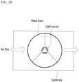
- FIG. 1 is a diagram schematically illustrating a metal foam photocatalyst apparatus according to an exemplary embodiment
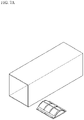
- FIG. 2A is a perspective view schematically illustrating the metal foam photocatalyst apparatus according to the exemplary embodiment
- FIG. 2B is a top plan view schematically illustrating the metal foam photocatalyst apparatus according to the exemplary embodiment
- FIG. 3 is a diagram schematically illustrating the metal foam photocatalyst apparatus according to the exemplary embodiment.
- a light source is disposed on a substrate, and a curved metal foam covers the light source. Air penetrates through the metal foam, and a photocatalyst formed in the metal foam reacts through the light source, thereby removing bad odors, microorganisms, mold, viruses, and the like contained in the air.
- the metal foam may be used as a catalyst carrier, and the porosity of the metal foam may be 90% or more, and accordingly, the performance of the photocatalyst apparatus may be improved through maximization of the specific surface area.
- the specific surface area of the metal foam may be about 1.1 m 2 /L to about 13 m 2 /L, and in this case, the light transmittance of the metal foam is maximized, and thus the performance of the photocatalyst apparatus may be maximized.
- the metal foam may include one or more metals such as nickel, iron, chromium, and aluminum to be manufactured thinly.
- the metal foam has flexibility, workability is high, and the metal foam may be manufactured in a curved shape to easily achieve uniformity of the light irradiation distance.
- the curved shape may have a dome shape of FIG. 1 , a cylindrical shape of FIGS. 2A and 2B , and a semi-cylindrical shape of FIG. 3 .
- the dome shape may be a spherical shape, a hexagonal shape, or an octagonal shape. Due to the curved shape of the metal foam, the light irradiation distance from the light to the metal foam may be equal at various positions.
- the curved shape of the metal foam may make the light penetration depth thin, and thus, the volume of air processed by the photocatalyst apparatus may be maintained, and the pressure drop may be maintained at a low level at the same time.
- HVAC Heating, Ventilation, Air Conditioning
- the photocatalyst may include TiO 2 .
- a noble metal such as platinum, rhodium, or palladium, may be applied on the photocatalyst, and in this case, the activation energy is further lowered.
- the photocatalyst may be used together with a cocatalyst, such as alumina, ceria, or zeolite.
- the light source may include one or more visible light or natural light, and ozone generation due to ultraviolet light may be prevented.
- An LED may be used as the light source.
- visible light or natural light generates less heat than ultraviolet light, the use of a heat radiating substrate or heat radiating fin is not required.
- a noble metal may be applied on the photocatalyst, or a cocatalyst may be used together with the photocatalyst.
- a reflector may be attached to the photocatalyst apparatus, and in this case, the performance of the photocatalyst apparatus may be further improved.
- the metal foam photocatalyst apparatus described above is applicable to the inside or outside of the vehicle HVAC apparatus, and is applicable to the discharge surface or the flow confluence part.
- the curved metal foam when the curved metal foam is compared with a flat honeycomb in the related art, the curved metal foam has a larger specific surface area than the flat honeycomb in the related art, and thus the volume thereof is reduced.
- the pressure drop may also be reduced.
- the pressure drop may be reduced, the amount of inflow and outflow of air may be increased, and noise may be reduced.
- the decomposition performance of the photocatalyst apparatus since the light irradiation length is uniform, the decomposition performance of the photocatalyst apparatus may be improved.
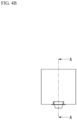
- FIGS. 4A to 4D Flow analysis for a photocatalyst apparatus using the flat honeycomb in the related art is illustrated in FIGS. 4A to 4D .
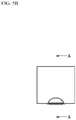
- a flow analysis for a metal foam photocatalyst apparatus in a dome shape is illustrated in FIGS. 5A to 5D
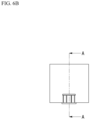
- a flow analysis for a metal foam photocatalyst apparatus in a cylindrical shape is illustrated in FIGS. 6A to 6D
- a flow analysis for a metal foam photocatalyst apparatus in a semi-cylindrical shape is illustrated in FIGS. 7A to 7D .
- Table 1 The flow analysis results of the flow analysis are illustrated in Table 1 below.
- the injected air has a velocity of 5 Am/sec, a flow rate of 455 kg/hr, and a temperature of 25°C.
- the volume of air is the same in the flat honeycomb photocatalyst apparatus in the related art, the dome-type metal foam photocatalyst apparatus, and the cylindrical metal foam photocatalyst apparatus, and the volume of air in the semi-cylindrical metal foam photocatalyst apparatus is about 3 times larger than the volume of air in the flat honeycomb photocatalyst apparatus in the related art.
- the curved metal foam photocatalyst apparatus in comparison with the flat photocatalyst apparatus in the related art, increases the distribution flow rate of air into the catalyst, thereby improving catalytic performance.
- the rise width of the pressure drop is small.
- the increase in the pressure drop is 3 times or less, and the distribution flow rate may be increased by about 5 times, even though the volume is increased 3 times compared to the flat photocatalyst apparatus in the related art. Accordingly, in the curved metal foam photocatalyst apparatus according to the exemplary embodiment, an increase in pressure drop may be minimized while an air distribution flow rate is increased.
- the vehicle HVAC apparatus includes a metal foam photocatalyst apparatus installed inside or outside.
- a metal foam photocatalyst apparatus installed inside or outside.
- the metal foam photocatalyst apparatus includes a substrate, a light source disposed on the substrate and irradiating light, a metal foam covering the light source on the substrate and having a curved shape, and a photocatalyst located on the metal foam and reacting to the light source, and removes one or more of bad odors, microorganisms, mold, or viruses contained in the air passing through the metal foam by the reaction of the photocatalyst.
- the metal foam photocatalyst apparatus may be attached to the air confluence part or the air outlet part of the vehicle HVAC apparatus.
- the metal foam photocatalyst apparatus may radiate heat without a heat radiation substrate or heat radiation fin.
Landscapes
- Chemical & Material Sciences (AREA)
- Engineering & Computer Science (AREA)
- Chemical Kinetics & Catalysis (AREA)
- Health & Medical Sciences (AREA)
- Environmental & Geological Engineering (AREA)
- Life Sciences & Earth Sciences (AREA)
- Organic Chemistry (AREA)
- Materials Engineering (AREA)
- Mechanical Engineering (AREA)
- Animal Behavior & Ethology (AREA)
- Epidemiology (AREA)
- Public Health (AREA)
- Veterinary Medicine (AREA)
- General Health & Medical Sciences (AREA)
- Analytical Chemistry (AREA)
- Biomedical Technology (AREA)
- Atmospheric Sciences (AREA)
- General Chemical & Material Sciences (AREA)
- Oil, Petroleum & Natural Gas (AREA)
- Disinfection, Sterilisation Or Deodorisation Of Air (AREA)
- Catalysts (AREA)
- Exhaust Gas Treatment By Means Of Catalyst (AREA)
- Air-Conditioning For Vehicles (AREA)
Abstract
Disclosed is a metal foam photocatalyst apparatus including: a substrate; a light source disposed on the substrate and irradiating light; a metal foam covering the light source on the substrate and having a curved shape, and a photocatalyst disposed on the metal foam and reacting to the light source, in which the metal foam photocatalyst apparatus removes one or more of bad odors, microorganisms, molds, or viruses contained in the air passing through the metal foam by the reaction of the photocatalyst.
Description
- This application claims priority to and the benefit of
Korean Patent Application No. 10-2021-0121140 filed in the Korean Intellectual Property Office on September 10, 2021 - A metal foam photocatalyst apparatus, and a vehicle Heating Ventilation Air Conditioning (HVAC) apparatus including the same are provided.
- In general, a plasma type ionizer is installed inside a vehicle Heating, Ventilation, Air Conditioning (HVAC) apparatus. The ionizer generates active oxygen to remove bad odors inside the vehicle, but at the same time, the ionizer generates ozone that is a carcinogen. Due to ozone regulation, the output of the plasma type ionizer is limited, and consequently the effect of removing bad odors is also reduced.
- In order to remove the bad odor inside the vehicle without generating ozone, a photocatalyst apparatus installed inside the vehicle HVAC apparatus may be used. Such a photocatalyst apparatus utilizes an ultraviolet light source, a TiO2 catalyst is applied to a planar honeycomb carrier, and a heat dissipation mechanism or a waterproof mechanism is used together. However, in a photocatalyst apparatus using an ultraviolet light source, heat is generated due to ultraviolet rays, and a heat dissipation mechanism is inevitably used together.
- The above information disclosed in this Background section is only for enhancement of understanding of the background of the invention, and therefore it may contain information that does not form the prior art that is already known in this country to a person of ordinary skill in the art.
- An exemplary embodiment has been made in an effort to remove bad odor in a vehicle interior and inside a vehicle Heating, Ventilation, Air Conditioning (HVAC) apparatus, suppress microbial growth, and remove mold and viruses.
- In addition to the above problems, the exemplary embodiment may be used to achieve other tasks not specifically mentioned.
- An exemplary embodiment provides a metal foam photocatalyst apparatus including: a substrate; a light source disposed on the substrate and irradiating light; a metal foam covering the light source on the substrate and having a curved shape, and a photocatalyst disposed on the metal foam and reacting to the light source, in which the metal foam photocatalyst apparatus removes one or more of bad odors, microorganisms, molds, or viruses contained in the air passing through the metal foam by the reaction of the photocatalyst.
- The light may be visible light or natural light.
- A noble metal may be applied on the photocatalyst.
- Alumina, ceria, zeolite, or one or more thereof may be disposed in the metal foam.
- The metal foam may have a dome shape.
- The metal foam may have a cylinder shape.
- The metal foam may have a semi-cylinder shape.
- The metal foam photocatalyst apparatus may further include a metal plate attached to the metal foam photocatalyst apparatus.
- An exemplary embodiment provides a vehicle Heating, Ventilation, Air Conditioning (HVAC) apparatus, including: a metal foam photocatalyst apparatus installed inside or outside, in which the metal foam photocatalyst apparatus includes: a substrate; a light source disposed on the substrate and irradiating light; a metal foam covering the light source on the substrate and having a curved shape, and a photocatalyst disposed on the metal foam and reacting to the light source, and the metal foam photocatalyst apparatus removes one or more of bad odors, microorganisms, molds, or viruses contained in the air passing through the metal foam by the reaction of the photocatalyst.
- The metal foam photocatalyst apparatus may be attached to an air confluence part or an air outlet part of the vehicle HVAC apparatus.
- In the vehicle HVAC apparatus, the metal foam photocatalyst apparatus may radiate heat without a heat radiation substrate or a heat radiation fin.
- According to the exemplary embodiments, the metal foam photocatalyst apparatus may be applied to the inside or outside of the vehicle HVAC apparatus, and may be applied to a discharge surface or a flow confluence part.
- According to the exemplary embodiments, the metal foam photocatalyst apparatus may utilize natural light, and a heat radiation device or a waterproof device may not be used.
- According to the exemplary embodiments, the metal foam photocatalyst apparatus uses metal foam having a high porosity as a catalyst carrier, thereby maximizing the specific surface area and maximizing the performance and maximizing the light transmittance.
- According to the exemplary embodiments, the metal foam photocatalyst apparatus uses metal foam with high flexibility as a catalyst carrier, so that it is possible to achieve high processability, make it possible to uniformize the light irradiation distance, maximize the performance by maximizing the specific surface area, maximize the light transmittance, and allow a reflective plate to be attached.
-
-
FIG. 1 is a diagram schematically illustrating a metal foam photocatalyst apparatus according to an exemplary embodiment. -
FIG. 2A is a perspective view schematically illustrating the metal foam photocatalyst apparatus according to the exemplary embodiment, andFIG. 2B is a top plan view schematically illustrating the metal foam photocatalyst apparatus according to the exemplary embodiment. -
FIG. 3 is a diagram schematically illustrating the metal foam photocatalyst apparatus according to the exemplary embodiment. -
FIG. 4A is a diagram schematically illustrating a photocatalyst apparatus in the related art,FIG. 4B is a side view of the photocatalyst apparatus in the related art,FIG. 4C is a cross-sectional view taken along line A-A ofFIG. 4B , andFIG. 4D is a diagram illustrating a flow rate analysis result for the photocatalyst apparatus in the related art ofFIGS. 4A to 4C . -
FIG. 5A is a diagram schematically illustrating a photocatalyst apparatus in the related art,FIG. 5B is a side view of the photocatalyst apparatus in the related art,FIG. 5C is a cross-sectional view taken along line A-A ofFIG. 5B , andFIG. 5D is a diagram illustrating a flow rate analysis result for the metal form photocatalyst apparatus in the related art ofFIGS. 5A to 5C . -
FIG. 6A is a diagram schematically illustrating a photocatalyst apparatus in the related art,FIG. 6B is a side view of the photocatalyst apparatus in the related art,FIG. 6C is a cross-sectional view taken along line A-A ofFIG. 6B , andFIG. 6D is a diagram illustrating a flow rate analysis result for the metal foam photocatalyst apparatus in the related art ofFIGS. 6A to 6C . -
FIG. 7A is a diagram schematically illustrating a photocatalyst apparatus in the related art,FIG. 7B is a side view of the photocatalyst apparatus in the related art,FIG. 7C is a cross-sectional view taken along line A-A ofFIG. 7B , andFIG. 7D is a diagram illustrating a flow rate analysis result for the metal foam photocatalyst apparatus in the related art ofFIGS. 7A to 7C . - In the following detailed description, only certain exemplary embodiments of the present invention have been illustrated and described, simply by way of illustration. However, the present invention can be variously implemented and is not limited to the following embodiments. Accordingly, the drawings and description are to be regarded as illustrative in nature and not restrictive. Like reference numerals designate like elements throughout the specification. In addition, in the case of a well-known published technology, a detailed description thereof will be omitted.
- Throughout the specification, unless explicitly described to the contrary, the word "comprise", and variations such as "comprises" or "comprising", will be understood to imply the inclusion of stated elements but not the exclusion of any other elements.
- Then, a metal foam photocatalyst apparatus according to an exemplary embodiment will be described in detail.
-
FIG. 1 is a diagram schematically illustrating a metal foam photocatalyst apparatus according to an exemplary embodiment,FIG. 2A is a perspective view schematically illustrating the metal foam photocatalyst apparatus according to the exemplary embodiment, andFIG. 2B is a top plan view schematically illustrating the metal foam photocatalyst apparatus according to the exemplary embodiment, andFIG. 3 is a diagram schematically illustrating the metal foam photocatalyst apparatus according to the exemplary embodiment. - Referring to
FIGS. 1 to 3 , a light source is disposed on a substrate, and a curved metal foam covers the light source. Air penetrates through the metal foam, and a photocatalyst formed in the metal foam reacts through the light source, thereby removing bad odors, microorganisms, mold, viruses, and the like contained in the air. - For example, the metal foam may be used as a catalyst carrier, and the porosity of the metal foam may be 90% or more, and accordingly, the performance of the photocatalyst apparatus may be improved through maximization of the specific surface area. In addition, the specific surface area of the metal foam may be about 1.1 m2/L to about 13 m2/L, and in this case, the light transmittance of the metal foam is maximized, and thus the performance of the photocatalyst apparatus may be maximized. In addition, the metal foam may include one or more metals such as nickel, iron, chromium, and aluminum to be manufactured thinly. Since the metal foam has flexibility, workability is high, and the metal foam may be manufactured in a curved shape to easily achieve uniformity of the light irradiation distance. For example, the curved shape may have a dome shape of
FIG. 1 , a cylindrical shape ofFIGS. 2A and2B , and a semi-cylindrical shape ofFIG. 3 . Also, the dome shape may be a spherical shape, a hexagonal shape, or an octagonal shape. Due to the curved shape of the metal foam, the light irradiation distance from the light to the metal foam may be equal at various positions. In addition, the curved shape of the metal foam may make the light penetration depth thin, and thus, the volume of air processed by the photocatalyst apparatus may be maintained, and the pressure drop may be maintained at a low level at the same time. In addition, when the photocatalyst apparatus is used in a vehicle Heating, Ventilation, Air Conditioning (HVAC) apparatus, the photocatalyst apparatus may not be installed on the inclined portion. - For example, the photocatalyst may include TiO2. A noble metal, such as platinum, rhodium, or palladium, may be applied on the photocatalyst, and in this case, the activation energy is further lowered. In addition, the photocatalyst may be used together with a cocatalyst, such as alumina, ceria, or zeolite.
- For example, the light source may include one or more visible light or natural light, and ozone generation due to ultraviolet light may be prevented. An LED may be used as the light source. In addition, since visible light or natural light generates less heat than ultraviolet light, the use of a heat radiating substrate or heat radiating fin is not required. Furthermore, in order to compensate for the low energy of visible light or natural light to remove bad odors, microorganisms, mold, viruses, and the like in the air, a noble metal may be applied on the photocatalyst, or a cocatalyst may be used together with the photocatalyst.
- In addition, a reflector may be attached to the photocatalyst apparatus, and in this case, the performance of the photocatalyst apparatus may be further improved.
- The metal foam photocatalyst apparatus described above is applicable to the inside or outside of the vehicle HVAC apparatus, and is applicable to the discharge surface or the flow confluence part.
- For example, when the curved metal foam is compared with a flat honeycomb in the related art, the curved metal foam has a larger specific surface area than the flat honeycomb in the related art, and thus the volume thereof is reduced. In addition, in the case of the curved metal foam, since the thickness is reduced compared to the same volume, the pressure drop may also be reduced. In addition, in the case of the curved metal foam, due to the consistent flow of air, the pressure drop may be reduced, the amount of inflow and outflow of air may be increased, and noise may be reduced. In addition, in the case of the curved metal foam, since the light irradiation length is uniform, the decomposition performance of the photocatalyst apparatus may be improved.
- Flow analysis for a photocatalyst apparatus using the flat honeycomb in the related art is illustrated in
FIGS. 4A to 4D . For the flow analysis using the curved metal foam according to the exemplary embodiment, a flow analysis for a metal foam photocatalyst apparatus in a dome shape is illustrated inFIGS. 5A to 5D , a flow analysis for a metal foam photocatalyst apparatus in a cylindrical shape is illustrated inFIGS. 6A to 6D , and a flow analysis for a metal foam photocatalyst apparatus in a semi-cylindrical shape is illustrated inFIGS. 7A to 7D . The flow analysis results of the flow analysis are illustrated in Table 1 below. The injected air has a velocity of 5 Am/sec, a flow rate of 455 kg/hr, and a temperature of 25°C. The volume of air is the same in the flat honeycomb photocatalyst apparatus in the related art, the dome-type metal foam photocatalyst apparatus, and the cylindrical metal foam photocatalyst apparatus, and the volume of air in the semi-cylindrical metal foam photocatalyst apparatus is about 3 times larger than the volume of air in the flat honeycomb photocatalyst apparatus in the related art.(Table 1) Flow analysis result Catalyst Flow Difference (%) Total ΔP(Pa) Flow Rate(kg/hr) Portion (based on Inlet flow rate) Pressure Drop Flow Rate Flat shape 2.09 5.11 1.12% 100% 100% Dome shape 2.46 7.93 1.74% 118% 155% Cylinder shape 3.32 12.63 2.78% 159% 247% Semi-cylinder shape 5.99 12.90 21.6% 286% 505% - Referring to Table 1, in comparison with the flat photocatalyst apparatus in the related art, the curved metal foam photocatalyst apparatus according to the exemplary embodiment increases the distribution flow rate of air into the catalyst, thereby improving catalytic performance. In addition, as the distribution flow rate of air increases, the rise width of the pressure drop is small. In the case of the semi-cylindrical metal foam photocatalyst apparatus, the increase in the pressure drop is 3 times or less, and the distribution flow rate may be increased by about 5 times, even though the volume is increased 3 times compared to the flat photocatalyst apparatus in the related art. Accordingly, in the curved metal foam photocatalyst apparatus according to the exemplary embodiment, an increase in pressure drop may be minimized while an air distribution flow rate is increased.
- Then, a vehicle HVAC apparatus according to an exemplary embodiment will be described in detail.
- The vehicle HVAC apparatus includes a metal foam photocatalyst apparatus installed inside or outside. The foregoing descriptions with reference to
FIGS. 1 to 7D may be equally applied to the description of the metal foam photocatalyst apparatus. - For example, the metal foam photocatalyst apparatus includes a substrate, a light source disposed on the substrate and irradiating light, a metal foam covering the light source on the substrate and having a curved shape, and a photocatalyst located on the metal foam and reacting to the light source, and removes one or more of bad odors, microorganisms, mold, or viruses contained in the air passing through the metal foam by the reaction of the photocatalyst.
- The metal foam photocatalyst apparatus may be attached to the air confluence part or the air outlet part of the vehicle HVAC apparatus.
- In the vehicle HVAC apparatus, the metal foam photocatalyst apparatus may radiate heat without a heat radiation substrate or heat radiation fin.
- While this invention has been described in connection with what is presently considered to be practical exemplary embodiments, it is to be understood that the invention is not limited to the disclosed embodiments. On the contrary, it is intended to cover various modifications and equivalent arrangements included within the spirit and scope of the appended claims.
Claims (11)
- A metal foam photocatalyst apparatus, comprising:a substrate;a light source disposed on the substrate and irradiating light;a metal foam covering the light source on the substrate and having a curved shape, anda photocatalyst disposed on the metal foam and reacting to the light sourcewherein the metal foam photocatalyst apparatus removes one or more of bad odors, microorganisms, molds, or viruses contained in the air passing through the metal foam by the reaction of the photocatalyst.
- The metal foam photocatalyst apparatus of claim 1, wherein:
the light is visible light or natural light. - The metal foam photocatalyst apparatus of claim 2, wherein:
a noble metal is applied on the photocatalyst. - The metal foam photocatalyst apparatus of claim 2, wherein:
alumina, ceria, zeolite, or one or more thereof are disposed in the metal foam. - The metal foam photocatalyst apparatus of claim 1, wherein:
the metal foam has a dome shape. - The metal foam photocatalyst apparatus of claim 1, wherein:
the metal foam has a cylinder shape. - The metal foam photocatalyst apparatus of claim 1, wherein:
the metal foam has a semi-cylinder shape. - The metal foam photocatalyst apparatus of claim 1, further comprising:
a metal plate attached to the metal foam photocatalyst apparatus. - A vehicle Heating, Ventilation, Air Conditioning (HVAC) apparatus, comprising:a metal foam photocatalyst apparatus installed inside or outside,wherein the metal foam photocatalyst apparatus includes:a substrate;a light source disposed on the substrate and irradiating light;a metal foam covering the light source on the substrate and having a curved shape, anda photocatalyst disposed on the metal foam and reacting to the light source, andthe metal foam photocatalyst apparatus removes one or more of bad odors, microorganisms, molds, or viruses contained in the air passing through the metal foam by the reaction of the photocatalyst.
- The vehicle HVAC apparatus of claim 9, wherein:
the metal foam photocatalyst apparatus is attached to an air confluence part or an air outlet part of the vehicle HVAC apparatus. - The vehicle HVAC apparatus of claim 9, wherein:
the metal foam photocatalyst apparatus radiates heat without a heat radiation substrate or without a heat radiation fin.
Applications Claiming Priority (1)
| Application Number | Priority Date | Filing Date | Title |
|---|---|---|---|
| KR1020210121140A KR102577305B1 (en) | 2021-09-10 | 2021-09-10 | Metal foam photocatalyst apparatus, and vehicle heating ventilation air conditioning including the same |
Publications (1)
| Publication Number | Publication Date |
|---|---|
| EP4147777A1 true EP4147777A1 (en) | 2023-03-15 |
Family
ID=83688658
Family Applications (1)
| Application Number | Title | Priority Date | Filing Date |
|---|---|---|---|
| EP22191992.1A Pending EP4147777A1 (en) | 2021-09-10 | 2022-08-24 | Metal foam photocatalyst apparatus, and vehicle heating ventilation air conditioning apparatus including the same |
Country Status (3)
| Country | Link |
|---|---|
| EP (1) | EP4147777A1 (en) |
| JP (1) | JP2023041052A (en) |
| KR (1) | KR102577305B1 (en) |
Citations (3)
| Publication number | Priority date | Publication date | Assignee | Title |
|---|---|---|---|---|
| US20120076700A1 (en) * | 2010-09-24 | 2012-03-29 | Dometic Corporation | Air purifier |
| WO2018043854A1 (en) * | 2016-09-02 | 2018-03-08 | (주)엘지하우시스 | Air purification module and manufacturing method therefor |
| US20180264162A1 (en) * | 2015-06-05 | 2018-09-20 | Hanon Systems | Photocatalytic apparatus and hvac equipment for vehicle comprising same |
Family Cites Families (7)
| Publication number | Priority date | Publication date | Assignee | Title |
|---|---|---|---|---|
| JP3080061U (en) * | 2001-03-06 | 2001-09-14 | 治夫 松田 | Air purifier with deodorization, restoration of deodorization ability, and sterilization effect |
| JP2006145183A (en) * | 2004-11-24 | 2006-06-08 | Kyataru:Kk | Air conditioner using highly functional photocatalyst |
| KR20100061665A (en) * | 2007-08-07 | 2010-06-08 | 리 안티마이크로바이얼 솔루션즈 엘엘씨 | Uv air treatment method and device |
| CN201263979Y (en) * | 2008-06-10 | 2009-07-01 | 马骧彬 | Photocatalysis active agent generating device as well as air purifier and engine using the device |
| KR101973536B1 (en) * | 2014-09-24 | 2019-05-02 | 한온시스템 주식회사 | Photocatalyst device |
| EP3002013A1 (en) * | 2014-10-02 | 2016-04-06 | Aero Engineering, S.L. | Air sterilizing unit |
| KR102627891B1 (en) * | 2018-01-22 | 2024-01-23 | 서울바이오시스 주식회사 | Deodorizing module and exsiccating device including the same |
-
2021
- 2021-09-10 KR KR1020210121140A patent/KR102577305B1/en active Active
-
2022
- 2022-08-24 EP EP22191992.1A patent/EP4147777A1/en active Pending
- 2022-09-09 JP JP2022144049A patent/JP2023041052A/en not_active Ceased
Patent Citations (3)
| Publication number | Priority date | Publication date | Assignee | Title |
|---|---|---|---|---|
| US20120076700A1 (en) * | 2010-09-24 | 2012-03-29 | Dometic Corporation | Air purifier |
| US20180264162A1 (en) * | 2015-06-05 | 2018-09-20 | Hanon Systems | Photocatalytic apparatus and hvac equipment for vehicle comprising same |
| WO2018043854A1 (en) * | 2016-09-02 | 2018-03-08 | (주)엘지하우시스 | Air purification module and manufacturing method therefor |
Also Published As
| Publication number | Publication date |
|---|---|
| KR102577305B1 (en) | 2023-09-08 |
| KR20230037968A (en) | 2023-03-17 |
| JP2023041052A (en) | 2023-03-23 |
Similar Documents
| Publication | Publication Date | Title |
|---|---|---|
| US9066988B1 (en) | Photocatalytic device with curved reflectors | |
| US10293072B2 (en) | Air purifier for transportation vehicles | |
| CN105530965B (en) | Photocatalyst device and vehicle air conditioner with the photocatalyst device | |
| US10143770B2 (en) | Photocatalytic apparatus and HVAC equipment for vehicle comprising same | |
| US9782510B1 (en) | Photocatalytic device with multi-metallic catalysts | |
| KR101935813B1 (en) | Photocatalyst device and air conditioner for vehicle | |
| KR102184608B1 (en) | Photocatalyst device | |
| KR20160098685A (en) | Space Sterilization Method with Multiple Wavelength Ultraviolet Lights and Space Sterilization Module Using the Method thereof | |
| EP4147777A1 (en) | Metal foam photocatalyst apparatus, and vehicle heating ventilation air conditioning apparatus including the same | |
| KR101914451B1 (en) | Air purification module and manufacturing method for the same | |
| CN206291340U (en) | light water ionization reactor | |
| US8926899B1 (en) | Photocatalytic devices | |
| KR102135617B1 (en) | Sterilizing module and home appliance including for the same | |
| US11786628B2 (en) | Air purifier | |
| JPH10235202A (en) | Photocatalyst and air purifier | |
| JP5123227B2 (en) | Heat collecting member for heater and heater equipped with the same | |
| CA3237358A1 (en) | Device and method for purifying a vehicle cabin | |
| CN216825654U (en) | Photocatalyst catalytic structure capable of averaging ultraviolet rays | |
| CN222773481U (en) | Photocatalyst air disinfection module | |
| KR20230004251A (en) | Photocatalyst device | |
| CN204816220U (en) | High -efficient air purification chamber | |
| KR20220125496A (en) | car ventilated seat | |
| CN221535024U (en) | Air sterilization device | |
| JPH1085606A (en) | Photocatalyst, photocatalyst filter, photocatalyst device, air conditioner, air purifier and air circulator | |
| CN217908444U (en) | Air sterilizing machine and space sterilizer are with hydroxyl module structure |
Legal Events
| Date | Code | Title | Description |
|---|---|---|---|
| PUAI | Public reference made under article 153(3) epc to a published international application that has entered the european phase |
Free format text: ORIGINAL CODE: 0009012 |
|
| STAA | Information on the status of an ep patent application or granted ep patent |
Free format text: STATUS: REQUEST FOR EXAMINATION WAS MADE |
|
| 17P | Request for examination filed |
Effective date: 20220824 |
|
| AK | Designated contracting states |
Kind code of ref document: A1 Designated state(s): AL AT BE BG CH CY CZ DE DK EE ES FI FR GB GR HR HU IE IS IT LI LT LU LV MC MK MT NL NO PL PT RO RS SE SI SK SM TR |