EP4147726B1 - Ultraviolet sterilization device - Google Patents
Ultraviolet sterilization device Download PDFInfo
- Publication number
- EP4147726B1 EP4147726B1 EP22158618.3A EP22158618A EP4147726B1 EP 4147726 B1 EP4147726 B1 EP 4147726B1 EP 22158618 A EP22158618 A EP 22158618A EP 4147726 B1 EP4147726 B1 EP 4147726B1
- Authority
- EP
- European Patent Office
- Prior art keywords
- hollow pipe
- ultraviolet
- ultraviolet light
- sterilization device
- liquid
- Prior art date
- Legal status (The legal status is an assumption and is not a legal conclusion. Google has not performed a legal analysis and makes no representation as to the accuracy of the status listed.)
- Active
Links
Images


Classifications
-
- C—CHEMISTRY; METALLURGY
- C02—TREATMENT OF WATER, WASTE WATER, SEWAGE, OR SLUDGE
- C02F—TREATMENT OF WATER, WASTE WATER, SEWAGE, OR SLUDGE
- C02F1/00—Treatment of water, waste water, or sewage
- C02F1/30—Treatment of water, waste water, or sewage by irradiation
- C02F1/32—Treatment of water, waste water, or sewage by irradiation with ultraviolet light
- C02F1/325—Irradiation devices or lamp constructions
-
- A—HUMAN NECESSITIES
- A23—FOODS OR FOODSTUFFS; TREATMENT THEREOF, NOT COVERED BY OTHER CLASSES
- A23L—FOODS, FOODSTUFFS OR NON-ALCOHOLIC BEVERAGES, NOT OTHERWISE PROVIDED FOR; PREPARATION OR TREATMENT THEREOF
- A23L5/00—Preparation or treatment of foods or foodstuffs, in general; Food or foodstuffs obtained thereby; Materials therefor
- A23L5/20—Removal of unwanted matter, e.g. deodorisation or detoxification
-
- C—CHEMISTRY; METALLURGY
- C02—TREATMENT OF WATER, WASTE WATER, SEWAGE, OR SLUDGE
- C02F—TREATMENT OF WATER, WASTE WATER, SEWAGE, OR SLUDGE
- C02F2201/00—Apparatus for treatment of water, waste water or sewage
- C02F2201/002—Construction details of the apparatus
- C02F2201/004—Seals, connections
-
- C—CHEMISTRY; METALLURGY
- C02—TREATMENT OF WATER, WASTE WATER, SEWAGE, OR SLUDGE
- C02F—TREATMENT OF WATER, WASTE WATER, SEWAGE, OR SLUDGE
- C02F2201/00—Apparatus for treatment of water, waste water or sewage
- C02F2201/32—Details relating to UV-irradiation devices
- C02F2201/322—Lamp arrangement
- C02F2201/3222—Units using UV-light emitting diodes [LED]
-
- C—CHEMISTRY; METALLURGY
- C02—TREATMENT OF WATER, WASTE WATER, SEWAGE, OR SLUDGE
- C02F—TREATMENT OF WATER, WASTE WATER, SEWAGE, OR SLUDGE
- C02F2201/00—Apparatus for treatment of water, waste water or sewage
- C02F2201/32—Details relating to UV-irradiation devices
- C02F2201/322—Lamp arrangement
- C02F2201/3227—Units with two or more lamps
-
- C—CHEMISTRY; METALLURGY
- C02—TREATMENT OF WATER, WASTE WATER, SEWAGE, OR SLUDGE
- C02F—TREATMENT OF WATER, WASTE WATER, SEWAGE, OR SLUDGE
- C02F2201/00—Apparatus for treatment of water, waste water or sewage
- C02F2201/32—Details relating to UV-irradiation devices
- C02F2201/322—Lamp arrangement
- C02F2201/3228—Units having reflectors, e.g. coatings, baffles, plates, mirrors
-
- C—CHEMISTRY; METALLURGY
- C02—TREATMENT OF WATER, WASTE WATER, SEWAGE, OR SLUDGE
- C02F—TREATMENT OF WATER, WASTE WATER, SEWAGE, OR SLUDGE
- C02F2303/00—Specific treatment goals
- C02F2303/04—Disinfection
-
- C—CHEMISTRY; METALLURGY
- C02—TREATMENT OF WATER, WASTE WATER, SEWAGE, OR SLUDGE
- C02F—TREATMENT OF WATER, WASTE WATER, SEWAGE, OR SLUDGE
- C02F2307/00—Location of water treatment or water treatment device
- C02F2307/06—Mounted on or being part of a faucet, shower handle or showerhead
-
- C—CHEMISTRY; METALLURGY
- C02—TREATMENT OF WATER, WASTE WATER, SEWAGE, OR SLUDGE
- C02F—TREATMENT OF WATER, WASTE WATER, SEWAGE, OR SLUDGE
- C02F2307/00—Location of water treatment or water treatment device
- C02F2307/12—Location of water treatment or water treatment device as part of household appliances such as dishwashers, laundry washing machines or vacuum cleaners
Definitions
- the present invention relates to the technical field of light sterilization, in particular to an ultraviolet sterilization device.
- ultraviolet rays can effectively inactivate bacteria and viruses, it has become a common sterilization method.
- ultraviolet Light Emitting Diodes LEDs
- AlGaN materials have developed rapidly.
- ultraviolet LED lamps have many advantages, such as small size, no mercury, fast response speed, low-voltage light source and so on, so that ultraviolet LED lamps are widely used in the fields of surface sterilization, liquid sterilization, air sterilization and so on.
- US2013/236353A1 discloses a device for disinfecting of gases and/or liquids, includes a tube of UV-transparent glass having a hollow interior space and a tube wall with a tube inside wall and a tube outside wall, as well as at least one UV-light source.
- the UV-transparent glass tube has an indentation extending into the interior space on at least one location and in the at least one indentation at least one UV-light source is arranged.
- the geometry causes the UV-light sources to be closer to the medium to be disinfected, so that a large portion of the UV-light reaches the interior space on a direct path through the glass, thus allowing fbr a low-loss transfer of the UV-light.
- WO2020/163733A1 discloses an UV light disinfecting system where UV light is distributed along the walls of a highly reflective tube.
- the UV light disinfecting system is flexible.
- the UV light disinfecting system includes at least one UV-LED positioned external to a highly reflective tube.
- the reflective tube includes a plurality of openings that are arranged so as to position each opening adjacent to a corresponding UV-LED such that UV light generated by the corresponding UV-LED is able to pass through the opening and into the reflective tube.
- the UV light is scattered along the length of the reflective tube to prevent or eliminate the presence of biofilms as well s to disinfect, sterilize, and purify and pathogens within the tube. Methods to mitigate the growth of biofilms in a water conduit is also provided.
- US2016/052802A1 discloses a water purification apparatus.
- a light source irradiates the water, passing through the flow passage, with ultraviolet light.
- the light source has a light emitting diode that emits the ultraviolet light whose wavelength is contained in a bandwidth of 220 nm or above to less than 300 nm, and the optical output in this wavelength bandwidth is in a range of 1 W to 50 W.
- the flow passage passes the water at a flow rate of 5 mL/second to 250 mL/second.
- the flow passage is formed by a wall surface having a tubular shape. A window through which the ultraviolet light is passed is provided in at least part of the wall surface.
- US 2020/189936 A1 discloses a fluid sterilizing device which includes barrel portion having a channel where fluid to be sterilized flows; inlet formed on one end portion side of the barrel portion; outlet formed on the other end portion side of the barrel portion; a light source that emits ultraviolet light toward the fluid; and a rectifier mounted inside the channel and having a cylindrical through hole.
- One of the existing devices for ultraviolet sterilization of liquid is provided with a liquid storage tank, and the liquid in the liquid storage tank is sterilized by long-term ultraviolet irradiation.
- the sterilization device can achieve the sterilization rate of 99.9%, and the sterilization device is cheap and relatively mature in technology.
- the above ultraviolet sterilization device will cause yellowing of the plastic of the tank body of the liquid storage tank and even result in powdering in severe cases. Therefore, in the prior art, a flow-through sterilization device is proposed. When the liquid flows through the sterilization cavity, it can achieve 99.9% of sterilization at a flow rate of several liters/minute.
- the above flow-through sterilization devices generally use ultraviolet LED light sources with higher ultraviolet power.
- the flow-through sterilization device needs to be designed with a more complex heat dissipation structure and a liquid flow structure, which is large in volume and high in cost, and brings difficulties to large-scale popularization.
- the embodiment of the present invention provides an ultraviolet sterilization device according to claim 1.
- the ultraviolet sterilization device of the invention is simple in structure, low in cost, and suitable for popularization and use in scenes such as household water dispensers, faucets, pet water dispensers, humidifiers, smart toilets and the like.
- 100-ultraviolet sterilization device 110-liquid passing pipe assembly; 111-shell; 1112-outer wall surface; 1114-inner wall surface; 112-hollow pipe; 1121-liquid inlet end; 1122-liquid outlet end; 113-accommodating groove; 114-upper cover; 1131-second light transmitting hole; 130-reflective film; 13 1-first light transmitting hole; 140-ultraviolet light source; 141-LED lamp; 142-substrate; 150-joint.
- ultraviolet sterilization has become a common sterilization method.
- One liquid sterilization device is provided with a liquid storage tank to sterilize the liquid in the liquid storage tank by using ultraviolet rays, but this method easily causes yellowing of the tank body of the liquid storage tank.
- the prior art also proposes a flow-through sterilization device, which sterilizes the liquid by external irradiation of the sterilization cavity when the liquid flows through the sterilization cavity.
- the existing flow-through sterilization devices generally use light sources with high ultraviolet power, and are correspondingly provided with a complex heat dissipation structure and a liquid flow structure, which are bulky and costly, and are not conducive to large-scale popularization and application.
- the present invention provides an ultraviolet sterilization device 100, as shown in FIGS. 1a-1e , which includes a liquid passing pipe assembly 110 and an ultraviolet light source 140.
- the liquid passing pipe assembly 110 includes a shell 111 and a transparent hollow pipe 112, the shell 111 is sleeved on the hollow pipe 112, the shell 111 is provided with an accommodating groove 113, and the ultraviolet light source 140 is provided in the accommodating groove 113.
- One end of the hollow pipe 112 is provided as a liquid inlet end 1121, and the other end thereof is provided as a liquid outlet end 1122, and the hollow pipe 112 is used for circulating liquid.
- the wall surface of the hollow pipe 112 is covered with a reflective film 130, the reflective film 130 is provided with first light transmitting holes 131 at the position corresponding to the ultraviolet light source 140, the first light transmitting holes 131 are communicated with the accommodating groove 113, so that the ultraviolet light emitted by the ultraviolet light source 140 is incident into the hollow pipe 112 and sterilizes the liquid circulating in the hollow pipe 112, and the reflective film 130 is used for scattering the ultraviolet light in different areas in the hollow pipe 112.
- the ultraviolet light source 140 is provided in the accommodating groove 113 provided on the shell 111.
- the transparent hollow pipe 112 is used for the liquid to be sterilized to flow.
- the wall of the hollow pipe 112 is covered with the reflective film 130.
- Ultraviolet light enters the hollow pipe 112 and irradiates on the wall surface of the hollow pipe 112, and the light ray is reflected by the reflective film 130 covered on the wall surface.
- ultraviolet rays are scattered to various areas in the hollow pipe 112, such as the vicinity of the liquid inlet end 1121, the middle area of the hollow pipe 112 and the vicinity of the liquid outlet end 1122, so as to sterilize the water in various areas in the hollow pipe 112 and obtain a good sterilization effect.
- the reflective film 130 is an opaque or partially transparent film layer, it is necessary to provide the first light transmitting holes 131 in the reflective film 130 so that the ultraviolet light emitted by the ultraviolet light source 140 can enter the hollow pipe 112 through the first light transmitting holes 131.
- the reflective film 130 is covered on the hollow pipe 112, and the ultraviolet light source 140 is scattered to different areas in the hollow pipe 112, so as to realize the sterilization and disinfection function of the liquid flowing through the hollow pipe 112.
- the device is simple in structure and low in cost, and can be widely applied to scenes such as household water dispensers, faucets, pet water dispensers, humidifiers, smart toilets and the like.
- the ultraviolet light source 140 is only provided at one side of the circumferential outer wall of the shell 111, although the ultraviolet rays are scattered by the reflective film 130, the illumination (i.e., the illumination intensity) of the ultraviolet light on the opposite sides of the circumferential outer wall of the hollow pipe 112 may not be uniform enough, and the illumination on the side where the ultraviolet light source 140 is provided is stronger, which will lead to the uneven sterilization degree of each area of the flowing liquid. Therefore, one group of ultraviolet light sources 140 is provided on each of the opposite sides of the circumferential outer wall of the shell 111, respectively.
- the illumination of ultraviolet light can be improved, and on the other hand, the uniformity of the illumination of ultraviolet light on the opposite sides of the circumferential outer wall of the hollow pipe 112 can be ensured, thereby ensuring the consistency of sterilization degree of all areas of the water.
- the ultraviolet light source 140 includes LED lamps 141, and LED lamps 141 in each group of ultraviolet light sources 140 include one or two LED lamps.
- the ultraviolet light source 140 is formed by welding an LED lamp 141 capable of emitting ultraviolet light on a ceramic or metal substrate 142.
- a circuit is preset on the ceramic or metal substrate 142. The circuit is used to control turning on or off the LED lamp 141.
- the reflective film 130 is opaque or not completely transparent, in order to make the ultraviolet light emitted by the ultraviolet light source 140 enter the hollow pipe 112 through the reflective film 130, it is necessary to provide the first light transmitting holes 131 on the reflective film 130.
- the larger the number of LED lamps 141 is the larger the area of the first light transmitting holes 131 is and the more incomplete the reflective film 130.
- the area of the first light transmitting holes 131 is larger. The incompleteness of the reflective film 130 will affect its reflection effect on ultraviolet light.
- the area of the first light transmitting hole 131 is reduced as much as possible, so as to ensure the integrity of the reflective film 130, thereby ensuring the better reflection effect of the reflective film 130 on light.
- the LED lamps 141 are correspondingly provided in the middle of the hollow pipe 112.
- the LED lamp 141 can be provided at any position of the circumferential outer wall of the hollow pipe 112. However, when the LED lamp is provided in the middle of the hollow pipe 112, the ultraviolet light emitted by the LED lamp 141 can be uniformly distributed on both ends of the hollow pipe 112 under the action of the reflective film 130. It can be understood that the LED lamp 141 directly irradiates the middle of the hollow pipe 112. Therefore, the intensity of ultraviolet light is the strongest. The ultraviolet light at both ends of the hollow pipe 112 is obtained by reflecting the ultraviolet light in the middle of the hollow pipe 112 through the reflective film 130, so that the intensity of ultraviolet light at both ends of the hollow pipe 112 is weak.
- the intensity of ultraviolet light on both ends symmetrical along the middle of the hollow pipe 112 is basically the same, and the intensity of ultraviolet light in the areas at both ends is not too weak.
- the areas at both ends also have certain sterilization ability.
- the ultraviolet light at the liquid inlet end 1121 first preliminarily sterilizes the liquid.
- the liquid flows into the middle area of the hollow pipe 112, because of the strong intensity of ultraviolet light here, the liquid can be thoroughly sterilized.
- the ultraviolet light at the liquid outlet end 1122 can further sterilize the liquid.
- the liquid is sterilized by ultraviolet light with a certain intensity, thus ensuring that the ultraviolet sterilization device 100 has a good sterilization effect.
- the LED lamp 141 is correspondingly provided in the middle of the hollow pipe 112, so that the LED lamp 141 is as far away from the liquid inlet end 1121 and the liquid outlet end 1122 as possible, which can prevent ultraviolet light from being reflected to the outside of the hollow pipe 112 as much as possible, thereby avoiding the lost energy of ultraviolet light, and the harm caused by ultraviolet light leakage.
- the radial size of the LED lamp 141 is less than or equal to 5 mm.
- the radial size of the LED lamp 141 should be selected according to the demand for the power of the LED lamp 141. Generally speaking, the larger the power of the LED lamp 141 is, the larger the size is, and the stronger the intensity of ultraviolet light is. However, in this embodiment, since the radial size of the LED lamp 141 will affect the size of the first light transmitting hole 131 provided in the reflective film 130, the larger the radial size of the LED lamp 141 is, the larger the first light transmitting hole 131 is. In order to ensure the integrity of the reflective film as much as possible, the radial size of the LED lamp 141 needs to be selected in an appropriate range.
- the radial size of the LED lamp 141 can be selected to be less than or equal to 5mm to meet the demand.
- the size of the LED lamp 141 can be a lamp bead with a size of ⁇ 5mmX5mm, and a smaller lamp bead with a size of ⁇ 3.5 mmX3.5 mm can be selected.
- the radial size of the first light transmitting hole 131 is greater than or equal to one time the size of the LED lamp 141 in the radial direction and less than or equal to three times the size of the LED lamp 141 in the radial direction.
- the radial size of the first light transmitting hole 131 is not less than the size of the LED lamp 141 in the radial direction, so as to ensure that all the ultraviolet light emitted by the LED lamp 141 passes through the first light transmitting hole 131 and irradiates into the hollow pipe 112, thus making full use of the light energy of the ultraviolet light.
- the radial size of the first light transmitting hole 131 is less than or equal to three times the size of the LED lamp 141 in the radial direction.
- the radial size of the first light transmitting hole 131 can be set to twice the size of the LED lamp 141 in the radial direction, so as to maintain the integrity of the reflective film 130 while ensuring that the ultraviolet light passes through the first light transmitting hole 131 as much as possible.
- the ultraviolet light source 140 is provided in the accommodating groove 113 of the shell.
- the accommodating groove 113 is provided on the outer wall surface 1112 of the shell 111.
- the opening of the accommodating groove 113 is away from the hollow pipe 112.
- the bottom of the accommodating groove 113 is provided with a second light transmitting hole 1131 at the position corresponding to the first light transmitting hole 131.
- the second light transmitting hole 1131 is communicated with the first light transmitting hole 131, so that the ultraviolet light emitted by the ultraviolet light source 140 is incident into hollow pipe 112 after passing through the second light transmitting hole 1131 and the first light transmitting hole 131.
- the second light transmitting holes 1131 are provided at the bottom of the accommodating groove 113 at the position corresponding to the LED lamps 141 of the ultraviolet light source 140.
- the number of the second light transmitting holes 1131 is the same as that of the LED lamps 141, and a plurality of second light transmitting holes 1131 are provided at intervals.
- the purpose of this arrangement is to ensure the integrity of the shell 111 as much as possible.
- an integral second light transmitting hole 1131 can also be directly provided at the bottom of the accommodating groove 113, so that the ultraviolet light emitted by each LED lamp 141 can pass through the second light transmitting hole 1131, which is not particularly limited here.
- an upper cover 114 is provided at the opening of the accommodating groove 113, and the upper cover 114 is used for protecting the ultraviolet light source 140.
- the accommodating groove 113 is provided on the inner wall surface 1114 of the shell 111, the opening of the accommodating groove 113 faces the hollow pipe 112, and the ultraviolet light emitted by the ultraviolet light source 140 is incident into the hollow pipe 112 through the first light transmitting hole 131.
- the accommodating groove 113 does not need to be provided with the second light transmitting hole 1131.
- the ultraviolet light can directly enter the first light transmitting hole 131 through the opening of the accommodating groove 113, and then be incident into the hollow pipe 112 from the first light transmitting hole 131. It can be understood that this arrangement mode makes the ultraviolet light source 140 closer to the hollow pipe 112, and the liquid circulating in the hollow pipe 112 can play a good cooling role to keep the excellent performance of the ultraviolet light source 140.
- the wavelength range of ultraviolet light emitted by the LED lamp 141 is 240-340 nm.
- Ultraviolet light in this wavelength range is referred to as deep ultraviolet light. Because bacteria have wavelength selectivity, ultraviolet light in this wavelength range generally has a better sterilization effect. Therefore, selecting the ultraviolet light source 140 in this wavelength range can effectively improve the sterilization effect of the ultraviolet sterilization device 100.
- the reflective film 130 is made of any one of inorganic material coating with diffuse reflectivity higher than 95%, fluorine-based organic material film with diffuse reflectivity higher than 95% or reflective medium film with specular reflectivity higher than 98%.
- the expanded polytetrafluoroethylene film with diffuse reflectivity higher than 95% is generally selected, which is relatively cheap and easy to process.
- the dielectric film of a distributed Bragg reflector with specular reflectivity greater than 99% can be selected.
- the reflective film 130 is provided on the outer wall surface of the hollow pipe 112.
- the reflective film 130 can also be provided on the inner wall surface 1114 of the hollow pipe 112.
- the reflective film 130 can generally be provided on the outer wall surface of the hollow pipe 112.
- the length of the hollow pipe 112 generally ranges from 40 mm to 100 mm.
- the inner diameter of the hollow pipe 112 ranges from 4 mm to 20 mm.
- the light emitting angle of the LED lamp 141 is less than or equal to 140 degrees. It can be understood that the length of the hollow pipe 112, the inner diameter of the hollow pipe 112 and the light emitting angle of the LED lamp 141 should be selected based on comprehensive consideration, so as to prevent the ultraviolet light emitted by the LED lamp 141 from escaping as much as possible, thereby making full use of the energy of the LED lamp 141 to sterilize the liquid flowing through the hollow pipe 112.
- the length of the hollow pipe 112 can be 40 mm to 100 mm according to the light emitting angle of the LED light source and the reflectivity of the reflective film 130.
- the length of the hollow pipe 112 is below 40mm, although the sterilization device for flowing water can be made smaller, the cumulative ultraviolet dose when the water flows through the hollow straight pipe is low, which will affect the sterilization rate.
- the size of the sterilization device for flowing water will also be significantly increased, but the cumulative ultraviolet dose does not significantly increase, which does not improve the sterilization effect obviously.
- the LED lamp 141 with a small light emitting angle when the inner diameter of the hollow pipe 112 is larger than 10mm, because the ultraviolet light will easily escape from both ends of the hollow pipe 112 due to the long path of each reflection of the ultraviolet light, it is possible to consider selecting the LED lamp 141 with a small light emitting angle. For example, the LED lamp 141 with a light emitting angle less than 90 degrees is selected, so as to restrict excessive ultraviolet light from escaping from both ends of the hollow pipe 112. On the contrary, when the diameter of the hollow pipe 112 is smaller than 10mm, the path of each reflection of ultraviolet light is short, and it is not easy for ultraviolet light to escape from both ends of the hollow pipe 112. Therefore, the LED lamp 141 with a large light emitting angle can be selected. For example, the LED lamp 141 with a light emitting angle greater than 90 degrees can be selected to ensure that the energy of ultraviolet light can be fully utilized, so as to obtain ultraviolet light irradiation with higher intensity when the liquid flows through the hollow pipe 112.
- the ultraviolet light source 140 can also be provided at both ends of the hollow pipe 112, that is, the liquid inlet end or the liquid outlet end. However, since there is liquid flowing through both ends, it is necessary to provide a waterproof structure to separate the ultraviolet light source 140 from the liquid. At this time, if the inner diameter of the hollow pipe 112 is relatively small, the space at the end of the hollow pipe is relatively small, so that it is generally difficult to provide the ultraviolet light source 140 at the end. When the inner diameter of the hollow pipe 112 is relatively large, the ultraviolet light source 140 can be provided at the end of the hollow pipe because the space at the end of the hollow pipe 112 is relatively large at this time.
- the inner diameter When the inner diameter is large, it is generally required to process liquid with a large flow rate, and the power of the ultraviolet light source 140 used at this time is relatively high.
- the ultraviolet light source 140 when the ultraviolet light source 140 is provided at the end, the liquid circulating in the hollow pipe 112 cannot cool the ultraviolet light source 140, so that it is necessary to additionally provide a heat dissipation base to dissipate heat from the ultraviolet light source 140, thus obtaining better optical characteristics.
- the inner diameter range of the hollow pipe 112 can be set to 6 mm to 15 mm.
- the ultraviolet sterilization device 100 provided in this embodiment has certain advantages in sterilizing flowing water with a small flow rate of 2L/min or less because of its small size.
- the hollow pipe 112 is made of any one of quartz, alumina or fluorine-based organic ultraviolet transparent material. It can be understood that in order to make the light of the ultraviolet light source 140 incident into the hollow pipe 112 to sterilize the water body flowing in the hollow pipe 112, the hollow pipe 112 should be made of transparent materials, and all the above materials can be used to make the transparent hollow pipe 112. Because the process of manufacturing the hollow pipe 112 of quartz is more mature and the cost is lower, a quartz hollow pipe 112 can generally be used.
- the liquid inlet end 1121 of the hollow pipe 112 is provided with a detachable joint 150.
- the end of the joint 150 is provided with an external thread
- the end of the shell 111 corresponding to the liquid inlet end 1121 is correspondingly provided with an internal thread
- the end of the joint 150 is screwed and fixed to the shell 111.
- the shell 111 can be made of heat shrinkable material.
- the heat shrinkable material has a memory function and covers the outer surface of the hollow pipe 112 after being heated and shrunk, and can play the roles of insulation, moisture protection, sealing and protection.
- the ultraviolet light source 140 is provided between the hollow pipe 112 and the shell 111, and with the heat shrinkable material, it is easier to fix the ultraviolet light source 140.
- the shell 111 can also be made of other metals, plastics and other materials, and it is generally considered to select materials that are not easy to yellow under irradiation of ultraviolet light.
- the ultraviolet sterilization device 100 provided by the present invention is modulated, with the selected length and inner diameter of the hollow pipe 112, by the light emitting angle of the ultraviolet light source 140 and the reflectivity of the reflective film 130.
- the ultraviolet light emitted by the ultraviolet light source 140 is irradiated into the hollow pipe 112 through the first light transmitting hole 131 on the reflective film 130, and is reflected by the reflective film 130 for many times, so that the illuminance of the ultraviolet light in the hollow pipe 112 is greatly enhanced, and in the straight pipe the illuminance in the middle is high and the illuminance at both ends is low.
- the area with the strongest ultraviolet illumination is concentrated in the center of the hollow pipe 112, and the illumination at both ends of the hollow pipe 112 is relatively weak. It can be understood that after the ultraviolet light is reflected by the reflective film 130, the superposition of the ultraviolet light may occur, thus enhancing the illumination of the ultraviolet light in the hollow pipe 112 to a certain extent.
- the specific size of the ultraviolet sterilization device 100 provided by the present invention will be illustrated by three specific examples hereinafter.
- the hollow pipe 112 of the ultraviolet sterilization device 100 is made of quartz.
- the quartz pipe has a length of 80mm, an inner diameter of 8mm, and a wall thickness of 1 mm.
- the reflective film 130 is an expanded polytetrafluoroethylene film with diffuse reflectivity of 95% in the ultraviolet wavelength range of 250-350 nm.
- the film thickness of the reflective film 130 is 0.5mm, and the reflective film 130 is provided with first light transmitting holes 131 with a size of 1mmX1mm.
- the ultraviolet light source 140 contains two LED lamps 141.
- the distance between two LED lamps 141 is 10mm, the bead size of the LED lamp 141 is 0.5mmX0.5mm, the radiation power of the LED lamp 141 is 15mW, and the light emitting angle is 140 degrees.
- the substrate 142 is an aluminum substrate 142.
- the outer shell 111 uses a plastic injection molding process to fix and protect the inner structure.
- the reflective film 130 is to fill the gap between the shell 111 and the hollow pipe 112, so that the thickness of the reflective film 130 can be selected according to the actual structural requirements.
- the distribution of ultraviolet illumination in the hollow pipe 112 of the ultraviolet sterilization device 100 provided in this example is analyzed hereinafter, and the actual sterilization test is carried out on the manufactured sample.
- the area with the strongest ultraviolet illuminance is in the middle of the quartz pipe.
- the illuminance at this position reaches about 100mW/cm 2 (the two dark areas in the middle of the figure correspond to two LED lamps), and the illuminance decreases gradually towards both ends, and drops to about 5mW/cm 2 within the range of 1cm from each end of the quartz pipe.
- the sterilization effect is the accumulation effect of illumination and time
- the average illumination in the quartz pipe can be used as one of the important performance indexes to measure the sterilization ability.
- the average illuminance in the quartz pipe of this embodiment is about 35.6mW/cm 2 . It should be noted that, compared with the numerical values shown in FIG 1f , the above illuminance values need to be converted into units.
- the actual sterilization rate of the ultraviolet sterilization device 100 provided in this example is tested.
- This sterilization rate test is to use Escherichia coli 8099 solution with a concentration of 4.5 ⁇ 10 4 cfu/ml (the unit of the number of colonies is cfu/ml).
- the solution flows in from the liquid inlet end 1121 of the quartz pipe at a flow rate of 1L/min, and then flows out from the liquid outlet end 1122 of the quartz pipe after sterilization in the cavity.
- the Escherichia coli 8099 solution which does not flow through the sterilization device is taken as the positive control solution. 100uL of sterilized solution (i.e.
- the sterilization rate can be calculated in at least two ways:
- the results are as follows (the unit of number of colonies is cfu/ml):
- the number of colonies of the positive control solution is 4.5 ⁇ 10 4 , while the number of colonies of the sterilized solution is 5.
- the sterilization rate can reach 99.99%.
- the LRV value can reach 4.
- the ultraviolet sterilization device 100 provided by this example can effectively sterilize the flowing water of 1L/min.
- the hollow pipe 112 of the ultraviolet sterilization device 100 is made of quartz.
- the quartz pipe has a length of 10mm, an inner diameter of 16.5mm, and a wall thickness of 2.5mm.
- the reflective film 130 is an expanded polytetrafluoroethylene film with diffuse reflectivity of 95% in the ultraviolet wavelength range of 250-350 nm.
- the film thickness of the reflective film 130 is 0.5mm, and the reflective film 130 is provided with first light transmitting holes 131 with a size of 2mmX2mm.
- the ultraviolet light source 140 contains two LED lamps 141.
- the bead size of the LED lamp 141 is 0.7mmX0.7mm, the radiation power of the LED lamp 141 is 30mW, and the light emitting angle is 120 degrees.
- the substrate 142 is a copper substrate 142.
- the main body of the shell 111 is made of aviation aluminum, and the joint at both ends of the shell 111 is made of plastic.
- the reflective film 130 preferably is attached to the inner wall of the quartz pipe, so that ultraviolet light can be reflected without passing through the side wall of the quartz pipe, avoiding the consumption of ultraviolet light energy, and thus ensuring a better reflection effect.
- the area with the strongest ultraviolet illumination is in the middle of the quartz pipe, where the illumination reaches about 40mW/cm 2 , and the illumination decreases gradually towards both ends, and drops to about 3mW/cm 2 within the range of 1cm from each end of the quartz pipe.
- the average illumination in the quartz pipe is about 12.5/cm 2 .
- the average illuminance in the cavity is reduced, but the sterilization space in the quartz pipe is increased, that is, the quartz pipe becomes thicker, and the flow rate of the liquid in the quartz pipe will slow down, that is, the irradiation time when the liquid flows into the ultraviolet sterilization device 100 will be increased.
- the test is also conducted at a flow rate of 1L/min, and the irradiation dose (illumination multiplied by time) of water flowing into the ultraviolet sterilization device 100 in this example is nearly twice that of the first example. That is to say, the larger the effective sterilization space is, the longer the corresponding sterilization time is, and the higher the corresponding processing capacity is.
- the hollow pipe 112 of the ultraviolet sterilization device 100 is made of quartz, and the length of the quartz pipe is 60mm.
- the quartz pipe is a square pipe with the inner dimension of 8mmX8mm and the wall thickness of 1 mm.
- the reflective film 130 is formed by evaporating distributed Bragg reflection (DBR) on the outer wall of the quartz pipe by optical coating.
- the reflective film 130 is formed by alternating 15 pairs of MgO layers and ZrO 2 layers, and has a reflectivity of 99% for ultraviolet light in the wavelength range of 250-350 nm.
- the reflective film 130 is provided with first through holes 131 with a size of 3.5mmX3.5mm.
- the ultraviolet light source 140 contains two LED lamps 141.
- the bead size of the LED lamp 141 is 3.5mmX3.5mm, the radiation power of the LED lamps 141 is 15mW, and the light emitting angle is 30 degrees.
- the substrate 142 is an aluminum substrate 142.
- the main body of the shell 111 is made of heat shrinkable sleeve, and the joint at both ends of the shell 111 is made of plastic.
- DBR is used as the reflective film 130.
- the manufacturing process is relatively complicated, the specular reflectivity of DBR is close to 100%, and higher ultraviolet illumination is obtained inside the quartz pipe.
- the average illumination inside the quartz pipe reaches about 100mW/cm 2 , thus obtaining a better sterilization effect.
- the ultraviolet sterilization devices of the second example and the third example have their own advantages compared with the ultraviolet sterilization device 100 of the first example, and have a sterilization effect not lower than that of the first example, the detection experiment of the actual sterilization effect will not be described in detail here.
Landscapes
- Engineering & Computer Science (AREA)
- Chemical & Material Sciences (AREA)
- Life Sciences & Earth Sciences (AREA)
- Health & Medical Sciences (AREA)
- Water Supply & Treatment (AREA)
- Environmental & Geological Engineering (AREA)
- Hydrology & Water Resources (AREA)
- Toxicology (AREA)
- Organic Chemistry (AREA)
- Nutrition Science (AREA)
- Food Science & Technology (AREA)
- Polymers & Plastics (AREA)
- Apparatus For Disinfection Or Sterilisation (AREA)
- Physical Water Treatments (AREA)
Description
- The present invention relates to the technical field of light sterilization, in particular to an ultraviolet sterilization device.
- Because ultraviolet rays can effectively inactivate bacteria and viruses, it has become a common sterilization method. In recent years, ultraviolet Light Emitting Diodes (LEDs) based on AlGaN materials have developed rapidly. Compared with traditional mercury lamps, ultraviolet LED lamps have many advantages, such as small size, no mercury, fast response speed, low-voltage light source and so on, so that ultraviolet LED lamps are widely used in the fields of surface sterilization, liquid sterilization, air sterilization and so on.
-
US2013/236353A1 discloses a device for disinfecting of gases and/or liquids, includes a tube of UV-transparent glass having a hollow interior space and a tube wall with a tube inside wall and a tube outside wall, as well as at least one UV-light source. The UV-transparent glass tube has an indentation extending into the interior space on at least one location and in the at least one indentation at least one UV-light source is arranged. The geometry causes the UV-light sources to be closer to the medium to be disinfected, so that a large portion of the UV-light reaches the interior space on a direct path through the glass, thus allowing fbr a low-loss transfer of the UV-light. -
WO2020/163733A1 discloses an UV light disinfecting system where UV light is distributed along the walls of a highly reflective tube. In some embodiments, the UV light disinfecting system is flexible. In at least one embodiment, the UV light disinfecting system includes at least one UV-LED positioned external to a highly reflective tube. In exemplary embodiments, the reflective tube includes a plurality of openings that are arranged so as to position each opening adjacent to a corresponding UV-LED such that UV light generated by the corresponding UV-LED is able to pass through the opening and into the reflective tube. The UV light is scattered along the length of the reflective tube to prevent or eliminate the presence of biofilms as well s to disinfect, sterilize, and purify and pathogens within the tube. Methods to mitigate the growth of biofilms in a water conduit is also provided. -
US2016/052802A1 discloses a water purification apparatus. In the water purification apparatus, a light source irradiates the water, passing through the flow passage, with ultraviolet light. The light source has a light emitting diode that emits the ultraviolet light whose wavelength is contained in a bandwidth of 220 nm or above to less than 300 nm, and the optical output in this wavelength bandwidth is in a range of 1 W to 50 W. The flow passage passes the water at a flow rate of 5 mL/second to 250 mL/second. The flow passage is formed by a wall surface having a tubular shape. A window through which the ultraviolet light is passed is provided in at least part of the wall surface. -
US 2020/189936 A1 discloses a fluid sterilizing device which includes barrel portion having a channel where fluid to be sterilized flows; inlet formed on one end portion side of the barrel portion; outlet formed on the other end portion side of the barrel portion; a light source that emits ultraviolet light toward the fluid; and a rectifier mounted inside the channel and having a cylindrical through hole. - One of the existing devices for ultraviolet sterilization of liquid is provided with a liquid storage tank, and the liquid in the liquid storage tank is sterilized by long-term ultraviolet irradiation. The sterilization device can achieve the sterilization rate of 99.9%, and the sterilization device is cheap and relatively mature in technology. However, under the long-term ultraviolet irradiation, the above ultraviolet sterilization device will cause yellowing of the plastic of the tank body of the liquid storage tank and even result in powdering in severe cases. Therefore, in the prior art, a flow-through sterilization device is proposed. When the liquid flows through the sterilization cavity, it can achieve 99.9% of sterilization at a flow rate of several liters/minute.
- However, in order to achieve the sterilization ability, the above flow-through sterilization devices generally use ultraviolet LED light sources with higher ultraviolet power. At the same time, the flow-through sterilization device needs to be designed with a more complex heat dissipation structure and a liquid flow structure, which is large in volume and high in cost, and brings difficulties to large-scale popularization.
- The embodiment of the present invention provides an ultraviolet sterilization device according to claim 1. The ultraviolet sterilization device of the invention is simple in structure, low in cost, and suitable for popularization and use in scenes such as household water dispensers, faucets, pet water dispensers, humidifiers, smart toilets and the like.
- Preferred features of the invention as recited in the dependent claims.
-
-
FIG 1a is an exploded view of an ultraviolet sterilization device according to an embodiment of the present invention. -
FIG 1b is a cross-sectional view of an ultraviolet sterilization device according to an embodiment of the present invention. -
FIG 1c is a schematic structural diagram of a hollow pipe of an ultraviolet sterilization device according to an embodiment of the present invention. -
FIG 1d is a schematic structural diagram of an ultraviolet light source of an ultraviolet sterilization device according to an embodiment of the present invention. -
FIG 1e is a schematic structural diagram of a shell of an ultraviolet sterilization device according to an embodiment of the present invention. -
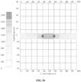
FIG 1f is a schematic diagram of illuminance distribution of an ultraviolet light source in a pipe of an ultraviolet sterilization device according to an embodiment of the present invention. -
FIG 2a is a cross-sectional view of another ultraviolet sterilization device according to an embodiment of the present invention. -
FIG 2b is a schematic diagram of illuminance distribution of an ultraviolet light source in a pipe of another ultraviolet sterilization device according to an embodiment of the present invention. -
FIG 3a is a cross-sectional view of another ultraviolet sterilization device according to an embodiment of the present invention. -
FIG 3b is a schematic diagram of illuminance distribution of another ultraviolet sterilization device according to an embodiment of the present invention. - 100-ultraviolet sterilization device; 110-liquid passing pipe assembly; 111-shell; 1112-outer wall surface; 1114-inner wall surface; 112-hollow pipe; 1121-liquid inlet end; 1122-liquid outlet end; 113-accommodating groove; 114-upper cover; 1131-second light transmitting hole; 130-reflective film; 13 1-first light transmitting hole; 140-ultraviolet light source; 141-LED lamp; 142-substrate; 150-joint.
- Because ultraviolet rays can inactivate bacteria and viruses, ultraviolet sterilization has become a common sterilization method. There are mainly two types of existing liquid sterilization devices. One liquid sterilization device is provided with a liquid storage tank to sterilize the liquid in the liquid storage tank by using ultraviolet rays, but this method easily causes yellowing of the tank body of the liquid storage tank. Based on this problem, the prior art also proposes a flow-through sterilization device, which sterilizes the liquid by external irradiation of the sterilization cavity when the liquid flows through the sterilization cavity. However, the existing flow-through sterilization devices generally use light sources with high ultraviolet power, and are correspondingly provided with a complex heat dissipation structure and a liquid flow structure, which are bulky and costly, and are not conducive to large-scale popularization and application.
- Embodiments of the present invention will be described with reference to the accompanying drawings hereinafter.
- The present invention provides an
ultraviolet sterilization device 100, as shown inFIGS. 1a-1e , which includes a liquidpassing pipe assembly 110 and anultraviolet light source 140. The liquidpassing pipe assembly 110 includes ashell 111 and a transparenthollow pipe 112, theshell 111 is sleeved on thehollow pipe 112, theshell 111 is provided with anaccommodating groove 113, and theultraviolet light source 140 is provided in theaccommodating groove 113. One end of thehollow pipe 112 is provided as aliquid inlet end 1121, and the other end thereof is provided as aliquid outlet end 1122, and thehollow pipe 112 is used for circulating liquid. The wall surface of thehollow pipe 112 is covered with areflective film 130, thereflective film 130 is provided with firstlight transmitting holes 131 at the position corresponding to theultraviolet light source 140, the firstlight transmitting holes 131 are communicated with theaccommodating groove 113, so that the ultraviolet light emitted by theultraviolet light source 140 is incident into thehollow pipe 112 and sterilizes the liquid circulating in thehollow pipe 112, and thereflective film 130 is used for scattering the ultraviolet light in different areas in thehollow pipe 112. - It should be noted that the
ultraviolet light source 140 is provided in theaccommodating groove 113 provided on theshell 111. The transparenthollow pipe 112 is used for the liquid to be sterilized to flow. The wall of thehollow pipe 112 is covered with thereflective film 130. Ultraviolet light enters thehollow pipe 112 and irradiates on the wall surface of thehollow pipe 112, and the light ray is reflected by thereflective film 130 covered on the wall surface. Under the action of thereflective film 130, ultraviolet rays are scattered to various areas in thehollow pipe 112, such as the vicinity of theliquid inlet end 1121, the middle area of thehollow pipe 112 and the vicinity of theliquid outlet end 1122, so as to sterilize the water in various areas in thehollow pipe 112 and obtain a good sterilization effect. Since thereflective film 130 is an opaque or partially transparent film layer, it is necessary to provide the firstlight transmitting holes 131 in thereflective film 130 so that the ultraviolet light emitted by theultraviolet light source 140 can enter thehollow pipe 112 through the first light transmittingholes 131. - In this embodiment, the
reflective film 130 is covered on thehollow pipe 112, and theultraviolet light source 140 is scattered to different areas in thehollow pipe 112, so as to realize the sterilization and disinfection function of the liquid flowing through thehollow pipe 112. The device is simple in structure and low in cost, and can be widely applied to scenes such as household water dispensers, faucets, pet water dispensers, humidifiers, smart toilets and the like. - In a possible embodiment, there are two groups of ultraviolet
light sources 140, and the two groups of ultravioletlight sources 140 are provided on the opposite sides of the circumferential outer wall of theshell 111, respectively. - It can be understood that if the ultraviolet
light source 140 is only provided at one side of the circumferential outer wall of theshell 111, although the ultraviolet rays are scattered by thereflective film 130, the illumination (i.e., the illumination intensity) of the ultraviolet light on the opposite sides of the circumferential outer wall of thehollow pipe 112 may not be uniform enough, and the illumination on the side where the ultravioletlight source 140 is provided is stronger, which will lead to the uneven sterilization degree of each area of the flowing liquid. Therefore, one group of ultravioletlight sources 140 is provided on each of the opposite sides of the circumferential outer wall of theshell 111, respectively. On the one hand, the illumination of ultraviolet light can be improved, and on the other hand, the uniformity of the illumination of ultraviolet light on the opposite sides of the circumferential outer wall of thehollow pipe 112 can be ensured, thereby ensuring the consistency of sterilization degree of all areas of the water. - In an alternative embodiment, as shown in
FIGS. 1b and1d , the ultravioletlight source 140 includesLED lamps 141, andLED lamps 141 in each group of ultravioletlight sources 140 include one or two LED lamps. - The ultraviolet
light source 140 is formed by welding anLED lamp 141 capable of emitting ultraviolet light on a ceramic ormetal substrate 142. A circuit is preset on the ceramic ormetal substrate 142. The circuit is used to control turning on or off theLED lamp 141. - It should be noted that there may be a single LED lamp or a plurality of
LED lamps 141, but because thereflective film 130 is opaque or not completely transparent, in order to make the ultraviolet light emitted by the ultravioletlight source 140 enter thehollow pipe 112 through thereflective film 130, it is necessary to provide the firstlight transmitting holes 131 on thereflective film 130. It can be understood that the larger the number ofLED lamps 141 is, the larger the area of the firstlight transmitting holes 131 is and the more incomplete thereflective film 130. Moreover, because there is more than one group of ultravioletlight sources 140, the area of the firstlight transmitting holes 131 is larger. The incompleteness of thereflective film 130 will affect its reflection effect on ultraviolet light. In order to protect the integrity of thereflective film 130, it is necessary to limit the number ofLED lamps 141 of each group of ultravioletlight sources 140, and then control the number and area of the first light transmitting holes 131. - In this embodiment, by limiting the number of
LED lamps 141, under the condition of meeting the irradiation intensity of ultraviolet light, the area of the firstlight transmitting hole 131 is reduced as much as possible, so as to ensure the integrity of thereflective film 130, thereby ensuring the better reflection effect of thereflective film 130 on light. - In some embodiments, as shown in
FIG 1b , theLED lamps 141 are correspondingly provided in the middle of thehollow pipe 112. - It should be noted that the
LED lamp 141 can be provided at any position of the circumferential outer wall of thehollow pipe 112. However, when the LED lamp is provided in the middle of thehollow pipe 112, the ultraviolet light emitted by theLED lamp 141 can be uniformly distributed on both ends of thehollow pipe 112 under the action of thereflective film 130. It can be understood that theLED lamp 141 directly irradiates the middle of thehollow pipe 112. Therefore, the intensity of ultraviolet light is the strongest. The ultraviolet light at both ends of thehollow pipe 112 is obtained by reflecting the ultraviolet light in the middle of thehollow pipe 112 through thereflective film 130, so that the intensity of ultraviolet light at both ends of thehollow pipe 112 is weak. However, in this arrangement mode, because the distance between each area of the areas at both ends of thehollow pipe 112 and the middle area is the same and not far away, the intensity of ultraviolet light on both ends symmetrical along the middle of thehollow pipe 112 is basically the same, and the intensity of ultraviolet light in the areas at both ends is not too weak. The areas at both ends also have certain sterilization ability. When the liquid flows into thehollow pipe 112 from theliquid inlet end 1121, the ultraviolet light at theliquid inlet end 1121 first preliminarily sterilizes the liquid. When the liquid flows into the middle area of thehollow pipe 112, because of the strong intensity of ultraviolet light here, the liquid can be thoroughly sterilized. When the liquid flows to theliquid outlet end 1122 through the middle area of thehollow tube 112, the ultraviolet light at theliquid outlet end 1122 can further sterilize the liquid. In this way, in the whole process of liquid flowing through thehollow pipe 112, the liquid is sterilized by ultraviolet light with a certain intensity, thus ensuring that theultraviolet sterilization device 100 has a good sterilization effect. - On the other hand, the
LED lamp 141 is correspondingly provided in the middle of thehollow pipe 112, so that theLED lamp 141 is as far away from theliquid inlet end 1121 and theliquid outlet end 1122 as possible, which can prevent ultraviolet light from being reflected to the outside of thehollow pipe 112 as much as possible, thereby avoiding the lost energy of ultraviolet light, and the harm caused by ultraviolet light leakage. - In addition, in order to prevent ultraviolet light from being emitted from both ends of the
hollow pipe 112 to the outside of thehollow pipe 112, it is not necessary to providereflective films 130 in the areas near theliquid inlet end 1121 and theliquid outlet end 1122 of thehollow pipe 112, so that the ultraviolet light cannot be reflected at the ends of thehollow pipe 112, thereby further ensuring that the ultraviolet light remains in theultraviolet sterilization device 100 without leakage. - In some embodiments, the radial size of the
LED lamp 141 is less than or equal to 5 mm. - The radial size of the
LED lamp 141 should be selected according to the demand for the power of theLED lamp 141. Generally speaking, the larger the power of theLED lamp 141 is, the larger the size is, and the stronger the intensity of ultraviolet light is. However, in this embodiment, since the radial size of theLED lamp 141 will affect the size of the firstlight transmitting hole 131 provided in thereflective film 130, the larger the radial size of theLED lamp 141 is, the larger the firstlight transmitting hole 131 is. In order to ensure the integrity of the reflective film as much as possible, the radial size of theLED lamp 141 needs to be selected in an appropriate range. In this embodiment, according to the application scenario of theultraviolet sterilization device 100 provided by the present invention, the radial size of theLED lamp 141 can be selected to be less than or equal to 5mm to meet the demand. For example, the size of theLED lamp 141 can be a lamp bead with a size of ≤5mmX5mm, and a smaller lamp bead with a size of ≤3.5 mmX3.5 mm can be selected. - Accordingly, the radial size of the first
light transmitting hole 131 is greater than or equal to one time the size of theLED lamp 141 in the radial direction and less than or equal to three times the size of theLED lamp 141 in the radial direction. - It can be understood that the radial size of the first
light transmitting hole 131 is not less than the size of theLED lamp 141 in the radial direction, so as to ensure that all the ultraviolet light emitted by theLED lamp 141 passes through the firstlight transmitting hole 131 and irradiates into thehollow pipe 112, thus making full use of the light energy of the ultraviolet light. The radial size of the firstlight transmitting hole 131 is less than or equal to three times the size of theLED lamp 141 in the radial direction. For example, the radial size of the firstlight transmitting hole 131 can be set to twice the size of theLED lamp 141 in the radial direction, so as to maintain the integrity of thereflective film 130 while ensuring that the ultraviolet light passes through the firstlight transmitting hole 131 as much as possible. - As for the specific arrangement position and arrangement mode of the ultraviolet
light source 140, the ultravioletlight source 140 is provided in theaccommodating groove 113 of the shell. - As shown in
FIGS. 1a-1b , theaccommodating groove 113 is provided on theouter wall surface 1112 of theshell 111. The opening of theaccommodating groove 113 is away from thehollow pipe 112. The bottom of theaccommodating groove 113 is provided with a secondlight transmitting hole 1131 at the position corresponding to the firstlight transmitting hole 131. The secondlight transmitting hole 1131 is communicated with the firstlight transmitting hole 131, so that the ultraviolet light emitted by the ultravioletlight source 140 is incident intohollow pipe 112 after passing through the secondlight transmitting hole 1131 and the firstlight transmitting hole 131. For the specific arrangement mode of the secondlight transmitting holes 1131, for example, the secondlight transmitting holes 1131 are provided at the bottom of theaccommodating groove 113 at the position corresponding to theLED lamps 141 of the ultravioletlight source 140. The number of the secondlight transmitting holes 1131 is the same as that of theLED lamps 141, and a plurality of secondlight transmitting holes 1131 are provided at intervals. The purpose of this arrangement is to ensure the integrity of theshell 111 as much as possible. Of course, an integral secondlight transmitting hole 1131 can also be directly provided at the bottom of theaccommodating groove 113, so that the ultraviolet light emitted by eachLED lamp 141 can pass through the secondlight transmitting hole 1131, which is not particularly limited here. - As shown in
FIG 1a, FIG 1b andFIG 2a , anupper cover 114 is provided at the opening of theaccommodating groove 113, and theupper cover 114 is used for protecting the ultravioletlight source 140. - In another embodiment out of the invention, as shown in
FIG 3a , theaccommodating groove 113 is provided on theinner wall surface 1114 of theshell 111, the opening of theaccommodating groove 113 faces thehollow pipe 112, and the ultraviolet light emitted by the ultravioletlight source 140 is incident into thehollow pipe 112 through the firstlight transmitting hole 131. At this time, because theaccommodating groove 113 is provided inside theshell 111, and the opening of theaccommodating groove 113 faces thehollow pipe 112, theaccommodating groove 113 does not need to be provided with the secondlight transmitting hole 1131. The ultraviolet light can directly enter the firstlight transmitting hole 131 through the opening of theaccommodating groove 113, and then be incident into thehollow pipe 112 from the firstlight transmitting hole 131. It can be understood that this arrangement mode makes the ultravioletlight source 140 closer to thehollow pipe 112, and the liquid circulating in thehollow pipe 112 can play a good cooling role to keep the excellent performance of the ultravioletlight source 140. - In an alternative embodiment, the wavelength range of ultraviolet light emitted by the
LED lamp 141 is 240-340 nm. Ultraviolet light in this wavelength range is referred to as deep ultraviolet light. Because bacteria have wavelength selectivity, ultraviolet light in this wavelength range generally has a better sterilization effect. Therefore, selecting the ultravioletlight source 140 in this wavelength range can effectively improve the sterilization effect of theultraviolet sterilization device 100. - Accordingly, the
reflective film 130 is made of any one of inorganic material coating with diffuse reflectivity higher than 95%, fluorine-based organic material film with diffuse reflectivity higher than 95% or reflective medium film with specular reflectivity higher than 98%. Specifically, from the view of difficulty and cost of the process, the expanded polytetrafluoroethylene film with diffuse reflectivity higher than 95% is generally selected, which is relatively cheap and easy to process. However, if a better sterilization ability and a smaller size are required, the dielectric film of a distributed Bragg reflector with specular reflectivity greater than 99% can be selected. - For example, as shown in
FIGS. 1b and2a , thereflective film 130 is provided on the outer wall surface of thehollow pipe 112. In fact, thereflective film 130 can also be provided on theinner wall surface 1114 of thehollow pipe 112. However, in actual process, since it is difficult to provide thereflective film 130 on theinner wall surface 1114 of thehollow pipe 112, and the liquid flowing in thehollow pipe 112 may chemically react with thereflective film 130, thereflective film 130 can generally be provided on the outer wall surface of thehollow pipe 112. - In order to prevent ultraviolet rays from escaping from the
liquid inlet end 1121 or theliquid outlet end 1122 of the hollow pipe, the length of thehollow pipe 112 generally ranges from 40 mm to 100 mm. The inner diameter of thehollow pipe 112 ranges from 4 mm to 20 mm. The light emitting angle of theLED lamp 141 is less than or equal to 140 degrees. It can be understood that the length of thehollow pipe 112, the inner diameter of thehollow pipe 112 and the light emitting angle of theLED lamp 141 should be selected based on comprehensive consideration, so as to prevent the ultraviolet light emitted by theLED lamp 141 from escaping as much as possible, thereby making full use of the energy of theLED lamp 141 to sterilize the liquid flowing through thehollow pipe 112. - It should be noted that the length of the
hollow pipe 112 can be 40 mm to 100 mm according to the light emitting angle of the LED light source and the reflectivity of thereflective film 130. When the length of thehollow pipe 112 is below 40mm, although the sterilization device for flowing water can be made smaller, the cumulative ultraviolet dose when the water flows through the hollow straight pipe is low, which will affect the sterilization rate. When the length of thehollow pipe 112 is above 100mm, the size of the sterilization device for flowing water will also be significantly increased, but the cumulative ultraviolet dose does not significantly increase, which does not improve the sterilization effect obviously. - In addition, when the inner diameter of the
hollow pipe 112 is larger than 10mm, because the ultraviolet light will easily escape from both ends of thehollow pipe 112 due to the long path of each reflection of the ultraviolet light, it is possible to consider selecting theLED lamp 141 with a small light emitting angle. For example, theLED lamp 141 with a light emitting angle less than 90 degrees is selected, so as to restrict excessive ultraviolet light from escaping from both ends of thehollow pipe 112. On the contrary, when the diameter of thehollow pipe 112 is smaller than 10mm, the path of each reflection of ultraviolet light is short, and it is not easy for ultraviolet light to escape from both ends of thehollow pipe 112. Therefore, theLED lamp 141 with a large light emitting angle can be selected. For example, theLED lamp 141 with a light emitting angle greater than 90 degrees can be selected to ensure that the energy of ultraviolet light can be fully utilized, so as to obtain ultraviolet light irradiation with higher intensity when the liquid flows through thehollow pipe 112. - In addition, it should be noted that the ultraviolet
light source 140 can also be provided at both ends of thehollow pipe 112, that is, the liquid inlet end or the liquid outlet end. However, since there is liquid flowing through both ends, it is necessary to provide a waterproof structure to separate the ultravioletlight source 140 from the liquid. At this time, if the inner diameter of thehollow pipe 112 is relatively small, the space at the end of the hollow pipe is relatively small, so that it is generally difficult to provide the ultravioletlight source 140 at the end. When the inner diameter of thehollow pipe 112 is relatively large, the ultravioletlight source 140 can be provided at the end of the hollow pipe because the space at the end of thehollow pipe 112 is relatively large at this time. When the inner diameter is large, it is generally required to process liquid with a large flow rate, and the power of the ultravioletlight source 140 used at this time is relatively high. However, when the ultravioletlight source 140 is provided at the end, the liquid circulating in thehollow pipe 112 cannot cool the ultravioletlight source 140, so that it is necessary to additionally provide a heat dissipation base to dissipate heat from the ultravioletlight source 140, thus obtaining better optical characteristics. The smaller the inner diameter is, the more delicate theultraviolet sterilization device 100 can be, but the corresponding flow rate that can be processed is also smaller. Generally, considering the sterilization ability and space requirements of theultraviolet sterilization device 100 in practical application scenarios, the inner diameter range of thehollow pipe 112 can be set to 6 mm to 15 mm. - The
ultraviolet sterilization device 100 provided in this embodiment has certain advantages in sterilizing flowing water with a small flow rate of 2L/min or less because of its small size. - In some embodiments, the
hollow pipe 112 is made of any one of quartz, alumina or fluorine-based organic ultraviolet transparent material. It can be understood that in order to make the light of the ultravioletlight source 140 incident into thehollow pipe 112 to sterilize the water body flowing in thehollow pipe 112, thehollow pipe 112 should be made of transparent materials, and all the above materials can be used to make the transparenthollow pipe 112. Because the process of manufacturing thehollow pipe 112 of quartz is more mature and the cost is lower, a quartzhollow pipe 112 can generally be used. - In order to facilitate the connection of the
hollow pipe 112 to a liquid source, such as a faucet, theliquid inlet end 1121 of thehollow pipe 112 is provided with adetachable joint 150. As shown inFIGS. 1a, 1b and2a , the end of the joint 150 is provided with an external thread, the end of theshell 111 corresponding to theliquid inlet end 1121 is correspondingly provided with an internal thread, and the end of the joint 150 is screwed and fixed to theshell 111. With this arrangement, it is convenient to replace the joint 150 according to the model of the liquid source, so that theultraviolet sterilization device 100 provided by the present invention can be used more flexibly and is suitable for a wider range of application scenarios. - In addition, in order to facilitate the manufacturing of the
shell 111, theshell 111 can be made of heat shrinkable material. The heat shrinkable material has a memory function and covers the outer surface of thehollow pipe 112 after being heated and shrunk, and can play the roles of insulation, moisture protection, sealing and protection. Especially when theaccommodating groove 113 is provided on theinner wall surface 1114 of theshell 111, the ultravioletlight source 140 is provided between thehollow pipe 112 and theshell 111, and with the heat shrinkable material, it is easier to fix the ultravioletlight source 140. In addition, theshell 111 can also be made of other metals, plastics and other materials, and it is generally considered to select materials that are not easy to yellow under irradiation of ultraviolet light. - Therefore, the
ultraviolet sterilization device 100 provided by the present invention is modulated, with the selected length and inner diameter of thehollow pipe 112, by the light emitting angle of the ultravioletlight source 140 and the reflectivity of thereflective film 130. The ultraviolet light emitted by the ultravioletlight source 140 is irradiated into thehollow pipe 112 through the firstlight transmitting hole 131 on thereflective film 130, and is reflected by thereflective film 130 for many times, so that the illuminance of the ultraviolet light in thehollow pipe 112 is greatly enhanced, and in the straight pipe the illuminance in the middle is high and the illuminance at both ends is low. At this time, the area with the strongest ultraviolet illumination is concentrated in the center of thehollow pipe 112, and the illumination at both ends of thehollow pipe 112 is relatively weak. It can be understood that after the ultraviolet light is reflected by thereflective film 130, the superposition of the ultraviolet light may occur, thus enhancing the illumination of the ultraviolet light in thehollow pipe 112 to a certain extent. - The specific size of the
ultraviolet sterilization device 100 provided by the present invention will be illustrated by three specific examples hereinafter. - In a first example, as shown in
FIGS. 1a-1e , thehollow pipe 112 of theultraviolet sterilization device 100 is made of quartz. The quartz pipe has a length of 80mm, an inner diameter of 8mm, and a wall thickness of 1 mm. Thereflective film 130 is an expanded polytetrafluoroethylene film with diffuse reflectivity of 95% in the ultraviolet wavelength range of 250-350 nm. The film thickness of thereflective film 130 is 0.5mm, and thereflective film 130 is provided with firstlight transmitting holes 131 with a size of 1mmX1mm. The ultravioletlight source 140 contains twoLED lamps 141. The distance between twoLED lamps 141 is 10mm, the bead size of theLED lamp 141 is 0.5mmX0.5mm, the radiation power of theLED lamp 141 is 15mW, and the light emitting angle is 140 degrees. Thesubstrate 142 is analuminum substrate 142. Theouter shell 111 uses a plastic injection molding process to fix and protect the inner structure. - It should be noted that another function of the
reflective film 130 is to fill the gap between theshell 111 and thehollow pipe 112, so that the thickness of thereflective film 130 can be selected according to the actual structural requirements. - The distribution of ultraviolet illumination in the
hollow pipe 112 of theultraviolet sterilization device 100 provided in this example is analyzed hereinafter, and the actual sterilization test is carried out on the manufactured sample. - As shown in
FIG 1f , it can be seen from the figure that the area with the strongest ultraviolet illuminance is in the middle of the quartz pipe. The illuminance at this position reaches about 100mW/cm2 (the two dark areas in the middle of the figure correspond to two LED lamps), and the illuminance decreases gradually towards both ends, and drops to about 5mW/cm2 within the range of 1cm from each end of the quartz pipe. Considering that the sterilization effect is the accumulation effect of illumination and time, the average illumination in the quartz pipe can be used as one of the important performance indexes to measure the sterilization ability. The average illuminance in the quartz pipe of this embodiment is about 35.6mW/cm2. It should be noted that, compared with the numerical values shown inFIG 1f , the above illuminance values need to be converted into units. - In order to show the actual sterilization effect, the actual sterilization rate of the
ultraviolet sterilization device 100 provided in this example is tested. This sterilization rate test is to use Escherichia coli 8099 solution with a concentration of 4.5×10⁴ cfu/ml (the unit of the number of colonies is cfu/ml). The solution flows in from theliquid inlet end 1121 of the quartz pipe at a flow rate of 1L/min, and then flows out from theliquid outlet end 1122 of the quartz pipe after sterilization in the cavity. In addition, the Escherichia coli 8099 solution which does not flow through the sterilization device is taken as the positive control solution. 100uL of sterilized solution (i.e. experimental samples) and 100ul of positive control solution are taken and are put into a constant temperature incubator at 37°C for culture after being smeared uniformly on the surface of eosin methylene blue agar. After 24 to 48 hours, the number of colonies of sterilized solution and positive control solution samples are observed and calculated. The sterilization rate can be calculated in at least two ways: - (1)
sterilization rate = (number of colonies of positive control - number of colonies of experimental samples)/number of colonies of positive control X100%; - (2) It is expressed by Logarithm Reduction Value (LRV), and the calculation formula is: LRV =-log (number of colonies of experimental samples/number of colonies of positive control).
- After the experiment, the results are as follows (the unit of number of colonies is cfu/ml):
The number of colonies of the positive control solution is 4.5×10⁴, while the number of colonies of the sterilized solution is 5. According to the above first formula, the sterilization rate can reach 99.99%. According to the above first formula, the LRV value can reach 4. - According to the above sterilization experiment data, it can be seen that the
ultraviolet sterilization device 100 provided by this example can effectively sterilize the flowing water of 1L/min. - In the second example, as shown in
FIG 2a , thehollow pipe 112 of theultraviolet sterilization device 100 is made of quartz. The quartz pipe has a length of 10mm, an inner diameter of 16.5mm, and a wall thickness of 2.5mm. Thereflective film 130 is an expanded polytetrafluoroethylene film with diffuse reflectivity of 95% in the ultraviolet wavelength range of 250-350 nm. The film thickness of thereflective film 130 is 0.5mm, and thereflective film 130 is provided with firstlight transmitting holes 131 with a size of 2mmX2mm. The ultravioletlight source 140 contains twoLED lamps 141. The bead size of theLED lamp 141 is 0.7mmX0.7mm, the radiation power of theLED lamp 141 is 30mW, and the light emitting angle is 120 degrees. Thesubstrate 142 is acopper substrate 142. The main body of theshell 111 is made of aviation aluminum, and the joint at both ends of theshell 111 is made of plastic. Considering the thick wall thickness of the quartz pipe in this example, although the reflection of thereflective film 130 can make the whole quartz pipe have higher ultraviolet illumination, because the thickness range of the wall surface of the quartz pipe is not an effective sterilization space, in this embodiment thereflective film 130 preferably is attached to the inner wall of the quartz pipe, so that ultraviolet light can be reflected without passing through the side wall of the quartz pipe, avoiding the consumption of ultraviolet light energy, and thus ensuring a better reflection effect. - As shown in
FIG 2b , it can be seen from the figure that the area with the strongest ultraviolet illumination is in the middle of the quartz pipe, where the illumination reaches about 40mW/cm2, and the illumination decreases gradually towards both ends, and drops to about 3mW/cm2 within the range of 1cm from each end of the quartz pipe. The average illumination in the quartz pipe is about 12.5/cm2. Although compared with the first example, the average illuminance in the cavity is reduced, but the sterilization space in the quartz pipe is increased, that is, the quartz pipe becomes thicker, and the flow rate of the liquid in the quartz pipe will slow down, that is, the irradiation time when the liquid flows into theultraviolet sterilization device 100 will be increased. Actually, the test is also conducted at a flow rate of 1L/min, and the irradiation dose (illumination multiplied by time) of water flowing into theultraviolet sterilization device 100 in this example is nearly twice that of the first example. That is to say, the larger the effective sterilization space is, the longer the corresponding sterilization time is, and the higher the corresponding processing capacity is. - In the third example, as shown in
FIG 3a , thehollow pipe 112 of theultraviolet sterilization device 100 is made of quartz, and the length of the quartz pipe is 60mm. The quartz pipe is a square pipe with the inner dimension of 8mmX8mm and the wall thickness of 1 mm. Thereflective film 130 is formed by evaporating distributed Bragg reflection (DBR) on the outer wall of the quartz pipe by optical coating. Thereflective film 130 is formed by alternating 15 pairs of MgO layers and ZrO2 layers, and has a reflectivity of 99% for ultraviolet light in the wavelength range of 250-350 nm. Thereflective film 130 is provided with first throughholes 131 with a size of 3.5mmX3.5mm. The ultravioletlight source 140 contains twoLED lamps 141. The bead size of theLED lamp 141 is 3.5mmX3.5mm, the radiation power of theLED lamps 141 is 15mW, and the light emitting angle is 30 degrees. Thesubstrate 142 is analuminum substrate 142. The main body of theshell 111 is made of heat shrinkable sleeve, and the joint at both ends of theshell 111 is made of plastic. - In this example, DBR is used as the
reflective film 130. Although the manufacturing process is relatively complicated, the specular reflectivity of DBR is close to 100%, and higher ultraviolet illumination is obtained inside the quartz pipe. As shown inFIG 3b , the average illumination inside the quartz pipe reaches about 100mW/cm2, thus obtaining a better sterilization effect. - As the ultraviolet sterilization devices of the second example and the third example have their own advantages compared with the
ultraviolet sterilization device 100 of the first example, and have a sterilization effect not lower than that of the first example, the detection experiment of the actual sterilization effect will not be described in detail here.
Claims (12)
- An ultraviolet sterilization device (100), comprising a liquid passing pipe assembly (110) and an ultraviolet light source (140), wherein the liquid passing pipe assembly (110) comprises a shell (111) and a transparent hollow pipe (112), the shell (111) is sleeved on the hollow pipe (112) and an accommodating groove (113) is provided on an outer wall surface of the shell (111), and the ultraviolet light source (140) is provided in the accommodating groove (113); wherein an opening of the accommodating groove (113) is away from the hollow pipe (112) and an upper cover (114) is provided at the opening of the accommodating groove (113), wherein the hollow pipe (112) has an end configured as a liquid inlet end (1121) and another end configured as a liquid outlet end (1122), and the hollow pipe (112) is configured for circulating liquid; a wall surface of the hollow pipe (112) is covered with a reflective film (130), the reflective film (130) is provided with first light transmitting holes (131) at a position corresponding to the ultraviolet light source (140), the first light transmitting holes (131) are communicated with the accommodating groove (113), a bottom of the accommodating groove (113) is provided with second light transmitting holes (1131) at positions corresponding to the first light transmitting holes (131), and the second light transmitting holes (1131) are communicated with the first light transmitting holes (131) so that ultraviolet light emitted by the ultraviolet light source (140) is incident into the hollow pipe (112) after passing through the second light transmitting holes (1131) and the first light transmitting holes (131) and sterilizes the liquid circulating in the hollow pipe (112), and the reflective film (130) is used for scattering the ultraviolet light in different areas in the hollow pipe (112).
- The ultraviolet sterilization device (100) according to claim 1, wherein the ultraviolet light source (140) comprises two groups of ultraviolet light sources (140), and the two groups of ultraviolet light sources (140) are provided on a circumferential wall of the shell (111) opposite to each other with respect to a middle area of the hollow pipe arranged between the liquid inlet end and the liquid outlet end."
- The ultraviolet sterilization device (100)according to claim 2, wherein the ultraviolet light source (140) comprises LED lamps (141), and a number of the LED lamps (141) in each group of ultraviolet light sources (140) is less than or equal to two; the LED lamps (141) are correspondingly provided in a circumferential outer wall of the hollow pipe (112) at a middle area of the hollow pipe (112) arranged between the liquid inlet end (1121) and the liquid outlet end (1122).
- The ultraviolet sterilization device (100) according to claim 3, wherein a radial size of each LED lamp (141) is less than or equal to 5 mm.
- The ultraviolet sterilization device (100) according to claim 4, wherein a radial size of each first light transmitting hole (131) is greater than or equal to one time a size of the LED lamp (141) in the radial direction and less than or equal to three times the size of the LED lamp (141) in the radial direction.
- The ultraviolet sterilization device (100) according to claim 5, wherein a wavelength range of ultraviolet light emitted by the LED lamp (141) is 240-340 nm.
- The ultraviolet sterilization device (100) according to any of claims 1 to 6, wherein the reflective film (130) is made of any one of inorganic material coating with diffuse reflectivity higher than 95%, fluorine-based organic material film with diffuse reflectivity higher than 95% or reflective medium film with specular reflectivity higher than 98%.
- The ultraviolet sterilization device (100) according to claim 7, wherein the reflective film (130) is provided on an outer wall surface (1112) of the hollow pipe (112).
- The ultraviolet sterilization device (100) according to any of claims 1 to 6, wherein a length of the hollow pipe (112) ranges from 40 mm to 100 mm; an inner diameter of the hollow pipe (112) ranges from 4 mm to 20 mm; the hollow pipe (112) is made of any one of quartz, alumina or fluorine-based organic ultraviolet transparent material.
- The ultraviolet sterilization device (100) according to claim 3, wherein the LED lamp (141) has a light emitting angle less than or equal to 140 degrees.
- The ultraviolet sterilization device (100) according to claim 1, wherein the liquid inlet end (1121) of the hollow pipe (112) is provided with a detachable joint (150), an end of the joint (150) is provided with an external thread, an end of the shell (111) corresponding to the liquid inlet end (1121) is provided with an internal thread, and the end of the joint (150) is screwed and fixed to the shell (111).
- The ultraviolet sterilization device (100) according to claim 1, wherein the shell (111) is made of heat shrinkable material.
Applications Claiming Priority (1)
| Application Number | Priority Date | Filing Date | Title |
|---|---|---|---|
| CN202111071127.9A CN113620374A (en) | 2021-09-13 | 2021-09-13 | Ultraviolet sterilization device |
Publications (3)
| Publication Number | Publication Date |
|---|---|
| EP4147726A1 EP4147726A1 (en) | 2023-03-15 |
| EP4147726C0 EP4147726C0 (en) | 2024-10-23 |
| EP4147726B1 true EP4147726B1 (en) | 2024-10-23 |
Family
ID=78389866
Family Applications (1)
| Application Number | Title | Priority Date | Filing Date |
|---|---|---|---|
| EP22158618.3A Active EP4147726B1 (en) | 2021-09-13 | 2022-02-24 | Ultraviolet sterilization device |
Country Status (3)
| Country | Link |
|---|---|
| US (1) | US12312257B2 (en) |
| EP (1) | EP4147726B1 (en) |
| CN (1) | CN113620374A (en) |
Families Citing this family (3)
| Publication number | Priority date | Publication date | Assignee | Title |
|---|---|---|---|---|
| CN114105250A (en) * | 2021-12-03 | 2022-03-01 | 马鞍山杰生半导体有限公司 | Sterilization device |
| CN114234305A (en) * | 2021-12-10 | 2022-03-25 | 中国科学院长春光学精密机械与物理研究所 | Hollow ultraviolet lamp tube for disinfection and sterilization of flowing fluid |
| CN116040891B (en) * | 2023-03-28 | 2023-06-06 | 江苏常淼环保工程有限公司 | Integrative clarification plant of soft water purification |
Citations (1)
| Publication number | Priority date | Publication date | Assignee | Title |
|---|---|---|---|---|
| US20200189936A1 (en) * | 2018-12-13 | 2020-06-18 | Stanley Electric Co., Ltd. | Fluid sterilizing device |
Family Cites Families (23)
| Publication number | Priority date | Publication date | Assignee | Title |
|---|---|---|---|---|
| DE2543418A1 (en) * | 1975-09-29 | 1977-04-07 | Stausberg | METHOD FOR DISINCLUDING WATER BY IRRADIATION WITH ULTRA-VIOLET LIGHT AND DEVICE FOR CARRYING OUT THE METHOD |
| US7169311B2 (en) * | 2001-10-17 | 2007-01-30 | Honeywell International, Inc. | Apparatus for disinfecting water using ultraviolet radiation |
| TW200607764A (en) * | 2004-08-16 | 2006-03-01 | xin-yan Liao | Tubular fluid cleansing and disinfecting device |
| US7270748B1 (en) * | 2004-09-21 | 2007-09-18 | Next Energy Wave, Inc. | Sterilizing water faucet |
| US7586104B2 (en) * | 2007-01-04 | 2009-09-08 | Tae-Hyoung Kim | Non-heating type fluid sterilizing apparatus |
| US20090208386A1 (en) * | 2007-10-23 | 2009-08-20 | Barsky Barry E | Germicidal water purification unit |
| US8742364B2 (en) * | 2010-08-31 | 2014-06-03 | Mag Aerospace Industries, Inc. | Systems and methods for disinfecting water |
| DE102011112994A1 (en) * | 2011-09-08 | 2013-03-14 | Schott Ag | Device for degerming gases and / or liquids |
| WO2013086274A1 (en) * | 2011-12-09 | 2013-06-13 | Mag Aerospace Industries, Inc. | Inline uv led water disinfection and heating |
| US10442704B2 (en) * | 2013-01-18 | 2019-10-15 | Sensor Electronic Technology, Inc. | Ultraviolet fluid disinfection system with feedback sensor |
| JP2014233646A (en) * | 2013-05-30 | 2014-12-15 | 日機装株式会社 | Water purifier |
| US9802840B2 (en) * | 2013-07-08 | 2017-10-31 | Sensor Electronic Technology, Inc. | Ultraviolet water disinfection system |
| CN110422906A (en) * | 2013-09-05 | 2019-11-08 | 首尔伟傲世有限公司 | Sterilizing unit |
| US10099944B2 (en) * | 2014-06-03 | 2018-10-16 | Sensor Electronic Technology, Inc. | Ultraviolet transparent enclosure |
| DE202014009076U1 (en) * | 2014-11-17 | 2016-02-18 | PURION GmbH | Apparatus for treating a medium with UV radiation |
| US10004821B2 (en) * | 2015-10-13 | 2018-06-26 | Sensor Electronic Technology, Inc. | Ultraviolet treatment of light absorbing liquids |
| US10869943B2 (en) * | 2016-03-31 | 2020-12-22 | Sensor Electronic Technology, Inc. | Treatment of fluid transport conduit with ultraviolet radiation |
| JP6419760B2 (en) * | 2016-08-30 | 2018-11-07 | 日機装株式会社 | Ultraviolet light sterilizer |
| CN106745480B (en) * | 2016-12-07 | 2023-09-15 | 青岛杰生电气有限公司 | Water-cooling deep ultraviolet light-emitting unit overcurrent type sterilizing and disinfecting device and water purifying equipment |
| CN208182660U (en) * | 2018-03-13 | 2018-12-04 | 上海缘图光电科技有限公司 | A kind of ultraviolet LED water purification system |
| KR102103973B1 (en) * | 2018-04-13 | 2020-04-23 | (주)포인트엔지니어링 | Ultraviolet rays sterilization module |
| CN113412240A (en) * | 2019-02-08 | 2021-09-17 | W.L.戈尔及同仁股份有限公司 | Ultraviolet light disinfection system |
| CN216106125U (en) * | 2021-09-13 | 2022-03-22 | 马鞍山杰生半导体有限公司 | Ultraviolet sterilization device |
-
2021
- 2021-09-13 CN CN202111071127.9A patent/CN113620374A/en active Pending
-
2022
- 2022-02-24 EP EP22158618.3A patent/EP4147726B1/en active Active
- 2022-03-09 US US17/690,582 patent/US12312257B2/en active Active
Patent Citations (1)
| Publication number | Priority date | Publication date | Assignee | Title |
|---|---|---|---|---|
| US20200189936A1 (en) * | 2018-12-13 | 2020-06-18 | Stanley Electric Co., Ltd. | Fluid sterilizing device |
Also Published As
| Publication number | Publication date |
|---|---|
| US20230079118A1 (en) | 2023-03-16 |
| EP4147726C0 (en) | 2024-10-23 |
| EP4147726A1 (en) | 2023-03-15 |
| CN113620374A (en) | 2021-11-09 |
| US12312257B2 (en) | 2025-05-27 |
Similar Documents
| Publication | Publication Date | Title |
|---|---|---|
| US10745295B2 (en) | Ultraviolet water disinfection system | |
| US10736980B2 (en) | Ultraviolet sterilization device | |
| US10815133B2 (en) | Fluid purification system and method | |
| US10787375B2 (en) | Ultraviolet water disinfection system | |
| US9802840B2 (en) | Ultraviolet water disinfection system | |
| JP6374403B2 (en) | Method and apparatus for liquid disinfection with light emitted from light emitting diodes | |
| US10099944B2 (en) | Ultraviolet transparent enclosure | |
| US20150144575A1 (en) | Uva germicidal device | |
| EP4147726A1 (en) | Ultraviolet sterilization device | |
| JP5890285B2 (en) | Device for sterilizing gases and / or liquids | |
| US20150246148A1 (en) | Compact system with high homogeneity of the radiation field | |
| TW201604140A (en) | Method, system and device for fluid treatment | |
| JP2016507367A (en) | Liquid purification apparatus and method | |
| KR20170028472A (en) | Fluid Sterilizer Using UV LED | |
| US20210047205A1 (en) | Ultraviolet sterilization tube and ultraviolet sterilization device | |
| US20150338336A1 (en) | Reflective Transparent Optical Chamber | |
| CN114514204A (en) | Fluid sterilizing device | |
| EP4260878B1 (en) | Uv fluid sterilizing apparatus | |
| CN216106125U (en) | Ultraviolet sterilization device | |
| CN220116269U (en) | Overcurrent type ultraviolet sterilization module | |
| CN223188974U (en) | Overcurrent type sterilizing device | |
| CN222312788U (en) | Sterilization water module | |
| JP2022062415A (en) | Fluid sterilization apparatus, fluid sterilization method, water treatment facility, and water purification equipment |
Legal Events
| Date | Code | Title | Description |
|---|---|---|---|
| PUAI | Public reference made under article 153(3) epc to a published international application that has entered the european phase |
Free format text: ORIGINAL CODE: 0009012 |
|
| STAA | Information on the status of an ep patent application or granted ep patent |
Free format text: STATUS: REQUEST FOR EXAMINATION WAS MADE |
|
| 17P | Request for examination filed |
Effective date: 20220224 |
|
| AK | Designated contracting states |
Kind code of ref document: A1 Designated state(s): AL AT BE BG CH CY CZ DE DK EE ES FI FR GB GR HR HU IE IS IT LI LT LU LV MC MK MT NL NO PL PT RO RS SE SI SK SM TR |
|
| STAA | Information on the status of an ep patent application or granted ep patent |
Free format text: STATUS: EXAMINATION IS IN PROGRESS |
|
| 17Q | First examination report despatched |
Effective date: 20230925 |
|
| GRAP | Despatch of communication of intention to grant a patent |
Free format text: ORIGINAL CODE: EPIDOSNIGR1 |
|
| STAA | Information on the status of an ep patent application or granted ep patent |
Free format text: STATUS: GRANT OF PATENT IS INTENDED |
|
| INTG | Intention to grant announced |
Effective date: 20240709 |
|
| GRAS | Grant fee paid |
Free format text: ORIGINAL CODE: EPIDOSNIGR3 |
|
| GRAA | (expected) grant |
Free format text: ORIGINAL CODE: 0009210 |
|
| STAA | Information on the status of an ep patent application or granted ep patent |
Free format text: STATUS: THE PATENT HAS BEEN GRANTED |
|
| AK | Designated contracting states |
Kind code of ref document: B1 Designated state(s): AL AT BE BG CH CY CZ DE DK EE ES FI FR GB GR HR HU IE IS IT LI LT LU LV MC MK MT NL NO PL PT RO RS SE SI SK SM TR |
|
| REG | Reference to a national code |
Ref country code: GB Ref legal event code: FG4D |
|
| REG | Reference to a national code |
Ref country code: CH Ref legal event code: EP |
|
| REG | Reference to a national code |
Ref country code: DE Ref legal event code: R096 Ref document number: 602022006943 Country of ref document: DE |
|
| REG | Reference to a national code |
Ref country code: IE Ref legal event code: FG4D |
|
| U01 | Request for unitary effect filed |
Effective date: 20241118 |
|
| U07 | Unitary effect registered |
Designated state(s): AT BE BG DE DK EE FI FR IT LT LU LV MT NL PT RO SE SI Effective date: 20241125 |
|
| U20 | Renewal fee for the european patent with unitary effect paid |
Year of fee payment: 4 Effective date: 20250107 |
|
| PG25 | Lapsed in a contracting state [announced via postgrant information from national office to epo] |
Ref country code: HR Free format text: LAPSE BECAUSE OF FAILURE TO SUBMIT A TRANSLATION OF THE DESCRIPTION OR TO PAY THE FEE WITHIN THE PRESCRIBED TIME-LIMIT Effective date: 20241023 Ref country code: IS Free format text: LAPSE BECAUSE OF FAILURE TO SUBMIT A TRANSLATION OF THE DESCRIPTION OR TO PAY THE FEE WITHIN THE PRESCRIBED TIME-LIMIT Effective date: 20250223 |
|
| PG25 | Lapsed in a contracting state [announced via postgrant information from national office to epo] |
Ref country code: ES Free format text: LAPSE BECAUSE OF FAILURE TO SUBMIT A TRANSLATION OF THE DESCRIPTION OR TO PAY THE FEE WITHIN THE PRESCRIBED TIME-LIMIT Effective date: 20241023 |
|
| PG25 | Lapsed in a contracting state [announced via postgrant information from national office to epo] |
Ref country code: NO Free format text: LAPSE BECAUSE OF FAILURE TO SUBMIT A TRANSLATION OF THE DESCRIPTION OR TO PAY THE FEE WITHIN THE PRESCRIBED TIME-LIMIT Effective date: 20250123 |
|
| PG25 | Lapsed in a contracting state [announced via postgrant information from national office to epo] |
Ref country code: GR Free format text: LAPSE BECAUSE OF FAILURE TO SUBMIT A TRANSLATION OF THE DESCRIPTION OR TO PAY THE FEE WITHIN THE PRESCRIBED TIME-LIMIT Effective date: 20250124 |
|
| PG25 | Lapsed in a contracting state [announced via postgrant information from national office to epo] |
Ref country code: PL Free format text: LAPSE BECAUSE OF FAILURE TO SUBMIT A TRANSLATION OF THE DESCRIPTION OR TO PAY THE FEE WITHIN THE PRESCRIBED TIME-LIMIT Effective date: 20241023 |
|
| PG25 | Lapsed in a contracting state [announced via postgrant information from national office to epo] |
Ref country code: RS Free format text: LAPSE BECAUSE OF FAILURE TO SUBMIT A TRANSLATION OF THE DESCRIPTION OR TO PAY THE FEE WITHIN THE PRESCRIBED TIME-LIMIT Effective date: 20250123 |
|
| PG25 | Lapsed in a contracting state [announced via postgrant information from national office to epo] |
Ref country code: SM Free format text: LAPSE BECAUSE OF FAILURE TO SUBMIT A TRANSLATION OF THE DESCRIPTION OR TO PAY THE FEE WITHIN THE PRESCRIBED TIME-LIMIT Effective date: 20241023 |
|
| PG25 | Lapsed in a contracting state [announced via postgrant information from national office to epo] |
Ref country code: SK Free format text: LAPSE BECAUSE OF FAILURE TO SUBMIT A TRANSLATION OF THE DESCRIPTION OR TO PAY THE FEE WITHIN THE PRESCRIBED TIME-LIMIT Effective date: 20241023 |
|
| PG25 | Lapsed in a contracting state [announced via postgrant information from national office to epo] |
Ref country code: CZ Free format text: LAPSE BECAUSE OF FAILURE TO SUBMIT A TRANSLATION OF THE DESCRIPTION OR TO PAY THE FEE WITHIN THE PRESCRIBED TIME-LIMIT Effective date: 20241023 |
|
| PLBE | No opposition filed within time limit |
Free format text: ORIGINAL CODE: 0009261 |
|
| STAA | Information on the status of an ep patent application or granted ep patent |
Free format text: STATUS: NO OPPOSITION FILED WITHIN TIME LIMIT |
|
| PG25 | Lapsed in a contracting state [announced via postgrant information from national office to epo] |
Ref country code: MC Free format text: LAPSE BECAUSE OF FAILURE TO SUBMIT A TRANSLATION OF THE DESCRIPTION OR TO PAY THE FEE WITHIN THE PRESCRIBED TIME-LIMIT Effective date: 20241023 |
|
| REG | Reference to a national code |
Ref country code: CH Ref legal event code: PL |
|
| 26N | No opposition filed |
Effective date: 20250724 |
|
| PG25 | Lapsed in a contracting state [announced via postgrant information from national office to epo] |
Ref country code: CH Free format text: LAPSE BECAUSE OF NON-PAYMENT OF DUE FEES Effective date: 20250228 |
|
| PG25 | Lapsed in a contracting state [announced via postgrant information from national office to epo] |
Ref country code: IE Free format text: LAPSE BECAUSE OF NON-PAYMENT OF DUE FEES Effective date: 20250224 |
|
| U20 | Renewal fee for the european patent with unitary effect paid |
Year of fee payment: 5 Effective date: 20260106 |