EP4146509B1 - Actionneur électromagnétique à commande manuelle et valve de frein de stationnement équipée d'un tel actionneur - Google Patents
Actionneur électromagnétique à commande manuelle et valve de frein de stationnement équipée d'un tel actionneur Download PDFInfo
- Publication number
- EP4146509B1 EP4146509B1 EP21722893.1A EP21722893A EP4146509B1 EP 4146509 B1 EP4146509 B1 EP 4146509B1 EP 21722893 A EP21722893 A EP 21722893A EP 4146509 B1 EP4146509 B1 EP 4146509B1
- Authority
- EP
- European Patent Office
- Prior art keywords
- actuator
- axis
- drive shaft
- shaft
- exertion
- Prior art date
- Legal status (The legal status is an assumption and is not a legal conclusion. Google has not performed a legal analysis and makes no representation as to the accuracy of the status listed.)
- Active
Links
Images


Classifications
-
- B—PERFORMING OPERATIONS; TRANSPORTING
- B60—VEHICLES IN GENERAL
- B60T—VEHICLE BRAKE CONTROL SYSTEMS OR PARTS THEREOF; BRAKE CONTROL SYSTEMS OR PARTS THEREOF, IN GENERAL; ARRANGEMENT OF BRAKING ELEMENTS ON VEHICLES IN GENERAL; PORTABLE DEVICES FOR PREVENTING UNWANTED MOVEMENT OF VEHICLES; VEHICLE MODIFICATIONS TO FACILITATE COOLING OF BRAKES
- B60T17/00—Component parts, details, or accessories of power brake systems not covered by groups B60T8/00, B60T13/00 or B60T15/00, or presenting other characteristic features
- B60T17/18—Safety devices; Monitoring
- B60T17/22—Devices for monitoring or checking brake systems; Signal devices
- B60T17/221—Procedure or apparatus for checking or keeping in a correct functioning condition of brake systems
-
- F—MECHANICAL ENGINEERING; LIGHTING; HEATING; WEAPONS; BLASTING
- F16—ENGINEERING ELEMENTS AND UNITS; GENERAL MEASURES FOR PRODUCING AND MAINTAINING EFFECTIVE FUNCTIONING OF MACHINES OR INSTALLATIONS; THERMAL INSULATION IN GENERAL
- F16K—VALVES; TAPS; COCKS; ACTUATING-FLOATS; DEVICES FOR VENTING OR AERATING
- F16K31/00—Actuating devices; Operating means; Releasing devices
- F16K31/02—Actuating devices; Operating means; Releasing devices electric; magnetic
- F16K31/06—Actuating devices; Operating means; Releasing devices electric; magnetic using a magnet, e.g. diaphragm valves, cutting off by means of a liquid
- F16K31/0675—Electromagnet aspects, e.g. electric supply therefor
- F16K31/0679—Electromagnet aspects, e.g. electric supply therefor with more than one energising coil
-
- B—PERFORMING OPERATIONS; TRANSPORTING
- B60—VEHICLES IN GENERAL
- B60T—VEHICLE BRAKE CONTROL SYSTEMS OR PARTS THEREOF; BRAKE CONTROL SYSTEMS OR PARTS THEREOF, IN GENERAL; ARRANGEMENT OF BRAKING ELEMENTS ON VEHICLES IN GENERAL; PORTABLE DEVICES FOR PREVENTING UNWANTED MOVEMENT OF VEHICLES; VEHICLE MODIFICATIONS TO FACILITATE COOLING OF BRAKES
- B60T13/00—Transmitting braking action from initiating means to ultimate brake actuator with power assistance or drive; Brake systems incorporating such transmitting means, e.g. air-pressure brake systems
- B60T13/74—Transmitting braking action from initiating means to ultimate brake actuator with power assistance or drive; Brake systems incorporating such transmitting means, e.g. air-pressure brake systems with electrical assistance or drive
- B60T13/745—Transmitting braking action from initiating means to ultimate brake actuator with power assistance or drive; Brake systems incorporating such transmitting means, e.g. air-pressure brake systems with electrical assistance or drive acting on a hydraulic system, e.g. a master cylinder
-
- H—ELECTRICITY
- H01—ELECTRIC ELEMENTS
- H01F—MAGNETS; INDUCTANCES; TRANSFORMERS; SELECTION OF MATERIALS FOR THEIR MAGNETIC PROPERTIES
- H01F7/00—Magnets
- H01F7/06—Electromagnets; Actuators including electromagnets
- H01F7/08—Electromagnets; Actuators including electromagnets with armatures
- H01F7/16—Rectilinearly-movable armatures
- H01F7/1607—Armatures entering the winding
-
- F—MECHANICAL ENGINEERING; LIGHTING; HEATING; WEAPONS; BLASTING
- F16—ENGINEERING ELEMENTS AND UNITS; GENERAL MEASURES FOR PRODUCING AND MAINTAINING EFFECTIVE FUNCTIONING OF MACHINES OR INSTALLATIONS; THERMAL INSULATION IN GENERAL
- F16D—COUPLINGS FOR TRANSMITTING ROTATION; CLUTCHES; BRAKES
- F16D2127/00—Auxiliary mechanisms
- F16D2127/06—Locking mechanisms, e.g. acting on actuators, on release mechanisms or on force transmission mechanisms
-
- H—ELECTRICITY
- H01—ELECTRIC ELEMENTS
- H01F—MAGNETS; INDUCTANCES; TRANSFORMERS; SELECTION OF MATERIALS FOR THEIR MAGNETIC PROPERTIES
- H01F7/00—Magnets
- H01F7/06—Electromagnets; Actuators including electromagnets
- H01F7/08—Electromagnets; Actuators including electromagnets with armatures
- H01F7/16—Rectilinearly-movable armatures
- H01F2007/1669—Armatures actuated by current pulse, e.g. bistable actuators
-
- H—ELECTRICITY
- H01—ELECTRIC ELEMENTS
- H01F—MAGNETS; INDUCTANCES; TRANSFORMERS; SELECTION OF MATERIALS FOR THEIR MAGNETIC PROPERTIES
- H01F7/00—Magnets
- H01F7/06—Electromagnets; Actuators including electromagnets
- H01F7/08—Electromagnets; Actuators including electromagnets with armatures
- H01F7/16—Rectilinearly-movable armatures
- H01F2007/1692—Electromagnets or actuators with two coils
-
- H—ELECTRICITY
- H01—ELECTRIC ELEMENTS
- H01F—MAGNETS; INDUCTANCES; TRANSFORMERS; SELECTION OF MATERIALS FOR THEIR MAGNETIC PROPERTIES
- H01F7/00—Magnets
- H01F7/06—Electromagnets; Actuators including electromagnets
- H01F7/08—Electromagnets; Actuators including electromagnets with armatures
- H01F7/18—Circuit arrangements for obtaining desired operating characteristics, e.g. for slow operation, for sequential energisation of windings, for high-speed energisation of windings
- H01F7/1844—Monitoring or fail-safe circuits
- H01F2007/185—Monitoring or fail-safe circuits with armature position measurement
Definitions
- the invention relates to the field of electromagnetic actuators and more particularly a bistable electromagnetic actuator with manual control, as well as an aircraft parking brake valve comprising such an actuator.
- actuators are known from the documents FROM 10 2010 000737 And US 5,365,210 .
- an aircraft wheel brake comprises friction elements, some integral with the wheel and others with a stator, and a brake cylinder arranged to exert sufficient force on the friction elements. to lock the aircraft wheel from rotating.
- the parking brake system comprises a hydraulic distributor commonly called PBSELV (from the English “Park Brake Selector Valve”) or PBSOV (from the English “Park Brake Shut-off Valve”), of which a drawer or a valve is generally moved by an electromechanical actuator.
- PBSELV from the English “Park Brake Selector Valve”
- PBSOV from the English “Park Brake Shut-off Valve”
- the electromechanical actuator comprises an electric motor with a stator and a rotor, and a screw/nut assembly, one of the elements of which is rotated by the rotor and the other element is forced to slide without rotation between two positions to control the movement of the drawer or the flap.
- the object of the invention is therefore to propose a linear actuator that can be controlled both electrically and manually to control a distributor such as that of an aircraft parking brake system.
- the gear formed between the mobile assembly and the drive shaft is reversible.
- the actuating member can thus be moved by excitation of the coil or rotation of the drive shaft so that the actuator is controllable both electrically and manually.
- the actuating member comprises a rod extending along the axis of force.
- the manual control device comprises a lever arranged at one end of the drive shaft to rotate said drive shaft.
- the actuator further comprises a feedback shaft mounted movable in rotation around a second axis orthogonal to the axis of effort.
- the copying shaft comprises a tooth cooperating with said at least one first relief or with at least one second relief of the actuating member so that a translation of the member of the mobile assembly causes a rotation of the copy tree.
- the actuator comprises a permanent magnet carried by the feedback shaft, and a Hall effect sensor arranged to detect a magnetic field emitted by the magnet when the feedback shaft is in an angular position corresponding to one of the extreme positions of the nucleus.
- the invention also relates to an aircraft parking brake valve comprising such an actuator and a movable distribution element between two service positions.
- the actuating member is connected to the distribution element to control a movement of said distribution element between two service positions.
- the distribution element is a valve or a drawer.
- the invention relates to a bistable electromagnetic actuator, generally designated 1, here controlling the movement of a distribution element 2 of an aircraft parking brake valve V between two service positions.
- the actuator 1 comprises, according to a particular embodiment of the invention, a fixed assembly generally designated by the reference 10, as well as a mobile assembly generally designated by the reference 20.
- the fixed assembly 10 has a generally cylindrical shape around a longitudinal axis , a set of four permanent magnets 14, two magnetic end pieces 15.1, 15.2 and a tube 16 of non-magnetic material.
- the frame 11 is made of ferromagnetic material and comprises a tubular body in two parts 11.1, 11.2 extending successively along the axis X. Each of the body parts 11.1, 11.2 is provided at its free end with a rim 11.3, 11.4 perpendicular to the axis X each defining an end opening of the carcass 11.
- the two coils 13 are each housed in an internal volume of the permanent magnet support 12 and are carried by said support to be centered on the axis X.
- Each coil 13 comprises two respective windings 13.1.
- the permanent magnet support 12 keeps the coils 13 spaced from one another and is trapped in the body parts 11.1, 11.2.
- the permanent magnet support 12 is made of ferromagnetic material.
- the permanent magnets 14 are symmetrically distributed around the axis
- the magnetic ends 15.1, 15.2 are coaxial with respect to the axis 11.3.
- the end piece 15.2 comprises a part extending projecting from the end opening defined by the rim 11.4.
- Each end piece 15.1, 15.2 has a tubular shape centered on the axis guided by the carcass 11 and the support 12 of permanent magnets.
- the tube 16 is centered on the axis
- the mobile assembly 20 comprises a core 21 made of ferromagnetic material and a non-magnetic rod 22 coupled to the core 21 to form an actuating member.
- the core 21 comprises a peripheral ring inside which extends radially a connecting web with the rod 22.
- the core 21 is able to slide along the axis X inside the tube 16 between two extreme positions in which said core 21 is partially facing the coils 13 and rests against one of the end pieces 15.1, 15.2.
- the end pieces 15.1, 15.2 thus form stops and also make it possible to close the magnetic flux of the coils 13 towards the core 21.
- the rod 22 has a generally cylindrical shape along the axis
- the rod 22 is thus movable along the axis X between a retracted position ( Figure 3 ) and an exit position ( Figure 4 ) corresponding to the extreme positions of core 21.
- the rod 22 passes axially through an opening made in the end piece 15.2 so that a distal end of the rod 22 extends projecting from the fixed assembly 10.
- the distal end of the rod 22 comprises a connection interface for be coupled to the distribution element 2, and is externally provided with a first annular groove 22.1 and a second groove 22.2.
- the fixed assembly 10 of the actuator is fixed integrally to a casing C of the valve V, via a fixing interface I made of non-magnetic material in which the carcass 11 is housed, so that the proximal end of the rod 22 extends inside a receiving volume L delimited by internal walls of the casing C.
- the fixed assembly 10 extends partly projecting from the fixing interface, which is itself partly in projecting from the casing C, and is covered by a cover K which is fixed to the fixing interface by extending projecting from the casing C.
- the actuator 1 also includes a manual control device 30 for manually moving the rod 22 between the retracted position and the extended position.
- the control device comprises a drive shaft 31 movable in rotation around an axis Y1 orthogonal to the axis exterior of the casing C.
- the end of the drive shaft 31 is provided with a lever 32 (visible on the figure 1 ) to rotate the drive shaft 31.
- the lever 32 here commonly called a “butterfly” shape, comprises two identical lugs 32.1, 32.2 which extend symmetrically on either side of the axis Y1 and in a plane passing through said axis Y1.
- the ears 32.1, 32.2 form gripping means for rotating the drive shaft 31.
- the drive shaft 31 comprises a tooth 31.1 engaged in the first groove 22.1 of the rod 22 so that a rotation of the drive shaft 31 around the axis Y1 causes a sliding of the rod 22 following the axis movement of the core 21 towards one or other of its extreme positions.
- the tooth 31.1 has a rounded shape and fits, when the drive shaft 31 pivots, in a cylinder centered on the axis Y1 and of diameter equal to an external diameter of the drive shaft 31.
- the lever 32 has an angular travel defined directly by the retracted position and the position of the rod 22, and indirectly by the extreme positions of the core 21. As illustrated in the figure 1 , this deflection angular is materialized by a first line T1 followed by the inscription “ON” and by a second line T2 followed by the inscription “OFF”.
- the first line T1 corresponds to an extreme angular position of the lever 32 in which the ear 32.1 is in the extension of said first line T1 and the rod 22 is in the extended position.
- the second line T2 corresponds to an extreme angular position of the lever 32 in which the ear 32.1 is in the extension of said second line T2 and the rod 22 is in the extended position.
- the lever 32 thus provides a visual indication of the position of the rod 22.
- the actuator 1 further comprises a feedback shaft 33 mounted in a wall of the casing C to have a movable end in rotation inside the volume L around an axis Y2 orthogonal to the axis X.
- the axes Y1, Y2 are parallel.
- the feedback shaft 33 and the drive shaft 31 extend on either side of the rod 22.
- the end of the copying shaft 33 comprises a tooth 33.1 engaged in the second groove 22.2 of the rod 22 so that sliding of the rod 22 along the axis of the Y2 axis.
- the tooth 33.1 has a rounded shape and fits, during the rotation of the feedback shaft 33, in a cylinder centered on the axis Y2 and of diameter equal to an external diameter of the feedback shaft 33.
- a permanent magnet 34 is fixed on an external surface of the feedback shaft 33 which is opposite the tooth 33.1, and a Hall effect sensor 35 is arranged inside the casing C so that the sensor 35 detects a magnetic field emitted by the magnet 34 when the feedback shaft 33 is in an angular position corresponding to the extended position of the rod 22.
- the sensor 35 is connected to an electronic unit (not shown here) allowing, for example , to go up to the level of the cockpit of the aircraft information relating to the position of the rod 22, and therefore to a state of the valve V.
- one of the two electromagnetic coils 13 is electrically powered so as to generate a magnetic field of attraction of the core 21.
- the other electromagnetic coil 13 n It is not electrically powered.
- the magnetic field generated by the coil 13 produces a magnetic flux which is guided by the ferromagnetic parts of the actuator 1.
- the magnetic flux forms a loop and successively passes through the end piece 15.1, 15.2 in contact with the electrically powered coil 13, the part 11.1, 11.2 of the carcass 11 in contact with said end piece 15.1, 15.2, the permanent magnet support 12, the permanent magnets 14 and the core 21.
- the core 21 then moves inside the tube 16 and is plated against the corresponding end piece 15.1, 15.2 of the fixed assembly 10.
- the core 21 is then separated from the other end piece 15.1, 15.2.
- the passage of the core 21 towards one or other of its extreme positions causes a sliding of the rod 22 towards the retracted position or the extended position, and therefore a movement of the distribution element 2 of the valve V between two positions in service.
- the sliding of the rod 22 in turn causes a rotation of the drive shaft 31 and a rotation of the feedback shaft 33.
- the angular position of the feedback shaft 33 is such that the permanent magnet 34 faces the sensor 35.
- the sensor 35 detects the magnetic field emitted by the magnet 34 , which allows the electronic unit to inform the pilot of the aircraft that the valve V is in a state corresponding to the extended position of the rod 22.
- the angular position of the feedback shaft 33 is such that the permanent magnet 34 is not facing the sensor 35.
- the sensor 35 then does not detect the magnetic field emitted by magnet 34.
- the drive shaft 31 and the feedback shaft 33 do not necessarily extend parallel to each other.
- drive shaft 31 and the feedback shaft 33 are on either side of the rod 22, they can also extend on the same side of the rod 22.
- the tooth 31.1 of the drive shaft 31 and the tooth 33.1 of the feedback shaft 33 can be engaged in one and the same groove 22.1.
- the distribution element 2 can for example be a valve or a drawer.
- the shape and dimensions of the rod 22 may be different from that described and illustrated.
- Each of the grooves can be replaced by at least one relief.
- Each of the grooves can be provided on the actuating member, the core or any other part linked in translation to the actuating member.
- the drive shaft can itself be provided with a magnet to also act as a feedback shaft.
- the invention can be used for any type of actuator regardless of the device operated.
Landscapes
- Engineering & Computer Science (AREA)
- Mechanical Engineering (AREA)
- Physics & Mathematics (AREA)
- Electromagnetism (AREA)
- General Engineering & Computer Science (AREA)
- Transportation (AREA)
- Power Engineering (AREA)
- Magnetically Actuated Valves (AREA)
- Electromagnets (AREA)
- Braking Arrangements (AREA)
Description
- L'invention concerne le domaine des actionneurs électromagnétiques et plus particulièrement un actionneur électromagnétique bistable à commande manuelle, ainsi qu'une valve de frein de parking d'aéronef comprenant un tel actionneur. Des exemples d'actionneurs sont connus des documents
DE 10 2010 000737 etUS 5 365 210 . - D'une manière générale, un frein de roue d'aéronef comporte des éléments de friction solidaires pour certains de la roue et pour d'autres d'un stator, et un vérin de frein agencé pour exercer sur les éléments de friction un effort suffisant pour bloquer en rotation la roue d'aéronef.
- Au parking, le vérin de frein est activé par un dispositif de commande dédié (appelé ici système de frein de parking) et distinct du dispositif de commande du vérin de frein en phase d'atterrissage. Le système de frein de parking comporte un distributeur hydraulique communément appelé PBSELV (de l'anglais « Park Brake Selector Valve ») ou PBSOV (de l'anglais « Park Brake Shut-off Valve »), dont un tiroir ou un clapet est généralement déplacé par un actionneur électromécanique.
- L'actionneur électromécanique comprend un moteur électrique avec un stator et un rotor, et un ensemble vis/écrou dont l'un des éléments est entraîné en rotation par le rotor et l'autre élément est astreint à coulisser sans rotation entre deux positions pour commander le déplacement du tiroir ou du clapet.
- L'engrenage formé par l'ensemble vis/écrou est réputé irréversible de sorte que ce type d'actionneur ne permet pas de commander manuellement le déplacement dudit tiroir ou dudit clapet. Or, pour des raisons de maintenance, il serait intéressant de pouvoir commander le distributeur PBSELV / PBSOV en l'absence d'électricité.
- Il serait par ailleurs intéressant de pouvoir commander manuellement le frein de parking en cas de panne électrique ou de dysfonctionnement électronique.
- L'invention a donc pour objet de proposer un actionneur linéaire commandable à la fois électriquement et manuellement pour piloter un distributeur tel que celui d'un système de frein de parking d'aéronef.
- A cet effet, on prévoit, selon l'invention, un actionneur électromagnétique bistable comprenant :
- une carcasse s'étendant suivant un axe d'effort de l'actionneur,
- deux bobines d'excitation disposées à l'intérieur de la carcasse et comportant au moins un enroulement autour de l'axe d'effort pour générer un flux magnétique de commande,
- un noyau mobile suivant l'axe d'effort et apte à être immobilisé selon deux positions extrêmes en fonction du flux magnétique généré par les bobines,
- un organe d'actionnement couplé au noyau pour former un ensemble mobile, et
- un dispositif de commande manuelle comportant un arbre d'entraînement mobile en rotation autour d'un premier axe orthogonal à l'axe d'effort, l'arbre d'entraînement comportant au moins une dent coopérant avec au moins un premier relief lié en translation à l'organe d'actionnement de sorte qu'une rotation de l'arbre d'entraînement engendre une translation de l'ensemble mobile.
- L'engrenage formé entre l'ensemble mobile et l'arbre d'entraînement est réversible. L'organe d'actionnement peut ainsi être déplacé par une excitation de la bobine ou une rotation de l'arbre d'entraînement de sorte que l'actionneur est commandable à la fois électriquement et manuellement.
- De manière particulière, l'organe d'actionnement comprend une tige s'étendant suivant l'axe d'effort.
- Selon une caractéristique particulière, le dispositif de commande manuelle comprend une manette agencée à une extrémité de l'arbre d'entraînement pour entraîner en rotation ledit arbre d'entraînement.
- Selon une autre caractéristique particulière, l'actionneur comprend en outre un arbre de recopie monté mobile en rotation autour d'un deuxième axe orthogonal à l'axe d'effort. L'arbre de recopie comporte une dent coopérant avec ledit au moins un premier relief ou avec au moins un deuxième relief de l'organe d'actionnement de sorte qu'une translation de l'organe de l'ensemble mobile entraîne une rotation de l'arbre de recopie.
- De manière particulière alors, l'actionneur comporte un aimant permanent porté par l'arbre de recopie, et un capteur à effet Hall agencé pour détecter un champ magnétique émis par l'aimant lorsque l'arbre de recopie est dans une position angulaire correspondant à l'une des positions extrêmes du noyau.
- L'invention concerne également une valve de frein de parking d'aéronef comprenant un tel actionneur et un élément de distribution mobile entre deux positions de service. L'organe d'actionnement est relié à l'élément de distribution pour commander un déplacement dudit élément de distribution entre deux positions de service.
- De manière particulière, l'élément de distribution est un clapet ou un tiroir.
- L'invention sera mieux comprise à la lumière de la description qui suit, laquelle est purement illustrative et non limitative, et doit être lue en regard des dessins annexés, parmi lesquels :
- la
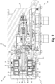
figure 1 est une vue en perspective d'une valve de frein de parking d'aéronef comprenant un actionneur selon un mode de réalisation particulier de l'invention ; - la
figure 2 est une vue en coupe de la valve illustrée à lafigure 1 selon un plan passant par un axe d'effort de l'actionneur ; - la
figure 3 est une vue en coupe simplifiée de l'actionneur illustré à lafigure 2 , dans un de ses états stables ; - la
figure 4 est une vue identique à lafigure 3 , dans laquelle l'actionneur est dans l'autre de ses états stables. - En référence aux
figures 1 et2 , l'invention concerne un actionneur électromagnétique bistable, généralement désigné en 1, commandant ici le déplacement d'un élément de distribution 2 d'une valve V de frein de parking d'aéronef entre deux positions de service. - L'actionneur 1 comprend, selon un mode de réalisation particulier de l'invention, un ensemble fixe désigné de façon générale par la référence 10, ainsi qu'un ensemble mobile désigné de façon générale par la référence 20.
- L'ensemble fixe 10 a une forme globalement cylindrique autour d'un axe X longitudinal et comprend, en allant de l'extérieur vers l'intérieur, une carcasse 11, un support 12 d'aimants permanents, deux bobines 13 d'excitation électromagnétiques, un ensemble de quatre aimants permanents 14, deux embouts 15.1, 15.2 magnétiques et un tube 16 en matériau non magnétique.
- La carcasse 11 est réalisée en matériau ferromagnétique et comporte un corps tubulaire en deux parties 11.1, 11.2 s'étendant successivement suivant l'axe X. Chacune des parties 11.1, 11.2 de corps est pourvue à son extrémité libre d'un rebord 11.3, 11.4 perpendiculaire à l'axe X définissant chacun une ouverture d'extrémité de la carcasse 11.
- Les deux bobines 13 sont chacune logées dans un volume interne du support 12 d'aimants permanents et sont portées par ledit support pour être centrées sur l'axe X. Chaque bobine 13 comprend deux enroulements 13.1 respectifs.
- Le support 12 d'aimants permanents maintient les bobines 13 espacées l'une de l'autre et est prisonnier des parties de corps 11.1, 11.2. Le support d'aimants permanents 12 est réalisée en matériau ferromagnétique.
- Les aimants permanents 14 sont symétriquement répartis autour de l'axe X entre les bobines 13 et sont collés à l'intérieur du support 12 pour générer un flux magnétique permanent en l'absence de courant dans lesdites bobines 13.
- Les embouts 15.1, 15.2 magnétiques sont coaxiaux par rapport à l'axe X et sont positionnés dans la carcasse 11 au contact des bobines voisines des extrémités longitudinales de ladite carcasse 11. L'embout 15.1 obture l'ouverture d'extrémité définie par le rebord 11.3. L'embout 15.2 comprend une partie s'étendant en saillie de l'ouverture d'extrémité définie par le rebord 11.4. Chaque embout 15.1, 15.2 présente une forme tubulaire centrée sur l'axe X et forme une butée au coulissement de l'ensemble mobile 20. Les embouts 15.1, 15.2 sont réalisés en matériau ferromagnétique afin de guider le flux magnétique produit par les bobines 13 et guidé par la carcasse 11 et le support 12 d'aimants permanents.
- Le tube 16 est centré sur l'axe X et s'étend entre les embouts 15.1, 15.2 à l'intérieur du support 12 d'aimants permanents pour former un organe de guidage de l'ensemble mobile 20.
- L'ensemble mobile 20 comprend un noyau 21 réalisé en matériau ferromagnétique et une tige 22 non magnétique couplée au noyau 21 pour former un organe d'actionnement.
- Le noyau 21 comprend un anneau périphérique à l'intérieur duquel s'étend radialement un voile de liaison avec la tige 22. Le noyau 21 est apte à coulisser suivant l'axe X à l'intérieur du tube 16 entre deux positions extrêmes dans lesquelles ledit noyau 21 est partiellement en regard des bobines 13 et est en appui contre l'un des embouts 15.1, 15.2. Les embouts 15.1, 15.2 forment ainsi des butées et permettent également de refermer le flux magnétique des bobines 13 vers le noyau 21.
- La tige 22 présente une forme globalement cylindrique suivant l'axe X. Une extrémité proximale de la tige est fixée solidairement au voile du noyau 21 par une vis 23 traversant ledit voile en son centre. La tige 22 est ainsi mobile suivant l'axe X entre une position rétractée (
figure 3 ) et une position sortie (figure 4 ) correspondants aux positions extrêmes du noyau 21. - La tige 22 traverse axialement une ouverture pratiquée dans l'embout 15.2 de sorte qu'une extrémité distale de la tige 22 s'étend en saillie de l'ensemble fixe 10. L'extrémité distale de la tige 22 comporte une interface de liaison pour être couplée à l'élément de distribution 2, et est extérieurement pourvue d'une première gorge 22.1 et une deuxième gorge 22.2 annulaires.
- L'ensemble fixe 10 de l'actionneur est fixé solidairement à un carter C de la valve V, via une interface de fixation I réalisée en matériau non magnétique dans laquelle la carcasse 11 est logée, de sorte que l'extrémité proximale de la tige 22 s'étende à l'intérieur d'un volume L de réception délimité par des parois internes du carter C. L'ensemble fixe 10 s'étend en partie en saillie de l'interface de fixation, qui est elle-même partiellement en saillie du carter C, et est coiffé par un capot K qui est fixé à l'interface de fixation en s'étendant en saillie du carter C.
- L'actionneur 1 comprend également un dispositif de commande manuelle 30 pour déplacer manuellement la tige 22 entre la position rétractée et la position sortie. Le dispositif de commande comporte un arbre d'entraînement 31 mobile en rotation autour d'un axe Y1 orthogonal à l'axe X. L'arbre d'entraînement 31 traverse une paroi latérale du carter C et possède une extrémité en saillie à l'extérieur du carter C. L'extrémité de l'arbre d'entraînement 31 est pourvue d'une manette 32 (visible sur la
figure 1 ) pour entraîner en rotation l'arbre d'entraînement 31. La manette 32, ici de forme couramment nommée « papillon », comprend deux oreilles 32.1, 32.2 identiques qui s'étendent symétriquement de part et d'autre de l'axe Y1 et dans un plan passant par ledit axe Y1. Les oreilles 32.1, 32.2 forment des moyens de préhension pour entraîner en rotation l'arbre d'entraînement 31. - Comme cela est visible sur la
figure 2 , l'arbre d'entraînement 31 comprend une dent 31.1 engagée dans la première gorge 22.1 de la tige 22 de sorte qu'une rotation de l'arbre d'entraînement 31 autour de l'axe Y1 entraîne un coulissement de la tige 22 suivant l'axe X vers la position sortie ou la position rétractée en fonction du sens de la rotation dudit arbre d'entraînement 31. Puisque la tige 22 est solidairement fixée au noyau 21, une rotation de l'arbre d'entraînement 31 provoque également un déplacement du noyau 21 vers l'une ou l'autre de ses positions extrêmes. - La dent 31.1 a une forme arrondie et s'inscrit, lorsque l'arbre d'entrainement 31 pivote, dans un cylindre centré sur l'axe Y1 et de diamètre égal à un diamètre extérieur de l'arbre d'entraînement 31.
- La manette 32 a un débattement angulaire défini directement par la position rétractée et la position de la tige 22, et indirectement par les positions extrêmes du noyau 21. Comme illustré sur la
figure 1 , ce débattement angulaire est matérialisé par un premier trait T1 suivi de l'inscription « ON » et par un deuxième trait T2 suivi de l'inscription « OFF ». Le premier trait T1 correspond à une position angulaire extrême de la manette 32 dans laquelle l'oreille 32.1 est dans le prolongement dudit premier trait T1 et la tige 22 est dans la position sortie. Le deuxième trait T2 correspond à une position angulaire extrême de la manette 32 dans laquelle l'oreille 32.1 est dans le prolongement dudit deuxième trait T2 et la tige 22 est dans la position sortie. La manette 32 permet ainsi d'avoir une indication visuelle sur la position de la tige 22. - L'actionneur 1 comprend en outre un arbre de recopie 33 monté dans une paroi du carter C pour avoir une extrémité mobile en rotation à l'intérieur du volume L autour d'un axe Y2 orthogonal à l'axe X. Les axes Y1, Y2 sont parallèles. L'arbre de recopie 33 et l'arbre d'entraînement 31 s'étendent de part et d'autre de la tige 22.
- L'extrémité de l'arbre de recopie 33 comporte une dent 33.1 engagée dans la deuxième gorge 22.2 de la tige 22 de sorte qu'un coulissement de la tige 22 selon l'axe X entraîne une rotation de l'arbre de recopie 33 autour de l'axe Y2. La dent 33.1 a une forme arrondie et s'inscrit, lors de la rotation de l'arbre de recopie 33, dans un cylindre centré sur l'axe Y2 et de diamètre égal à un diamètre extérieur de l'arbre de recopie 33.
- Par ailleurs, un aimant 34 permanent est fixé sur une surface externe de l'arbre de recopie 33 qui est opposée à la dent 33.1, et un capteur 35 à effet Hall est agencé à l'intérieur du carter C de sorte que le capteur 35 détecte un champ magnétique émis par l'aimant 34 lorsque l'arbre de recopie 33 est dans une position angulaire correspondant à la position sortie de la tige 22. Le capteur 35 est relié à une unité électronique (non représentée ici) permettant, par exemple, de remonter au niveau du cockpit de l'aéronef une information relative à la position de la tige 22, et donc à un état de la valve V.
- Le fonctionnement de l'actionneur va maintenant être décrit.
- Pour déplacer le noyau 21 vers l'une ou l'autre de ses positions extrêmes, l'une des deux bobines 13 électromagnétiques est alimentée électriquement de manière à générer un champ magnétique d'attraction du noyau 21. L'autre bobine 13 électromagnétique n'est pas alimentée électriquement.
- Le champ magnétique généré par la bobine 13 produit un flux magnétique qui est guidé par les parties ferromagnétiques de l'actionneur 1. Le flux magnétique forme une boucle et traverse successivement l'embout 15.1, 15.2 au contact de la bobine 13 alimentée électriquement, la partie 11.1, 11.2 de la carcasse 11 en contact avec ledit embout 15.1, 15.2, le support d'aimants permanents 12, les aimants permanents 14 et le noyau 21. Le noyau 21 se déplace alors à l'intérieur du tube 16 et est plaqué contre l'embout 15.1, 15.2 correspondant de l'ensemble fixe 10. Le noyau 21 se trouve alors écarté de l'autre embout 15.1, 15.2.
- Le passage du noyau 21 vers l'une ou l'autre de ses positions extrêmes engendre un coulissement de la tige 22 vers la position rétractée ou la position sortie, et donc un déplacement de l'élément de distribution 2 de la valve V entre deux positions en service. Le coulissement de la tige 22 entraîne à son tour une rotation de l'arbre d'entraînement 31 et une rotation de l'arbre de recopie 33.
- Lorsque que la tige 22 est dans la position sortie, la position angulaire de l'arbre de recopie 33 est telle que l'aimant 34 permanent est en regard du capteur 35. Le capteur 35 détecte alors le champ magnétique émis par l'aimant 34, ce qui permet à l'unité électronique d'informer le pilote de l'aéronef que la valve V est dans un état correspondant à la position sortie de la tige 22.
- Lorsque que la tige 22 est dans sa position rétractée, la position angulaire de l'arbre de recopie 33 est telle que l'aimant 34 permanent n'est pas en regard du capteur 35. Le capteur 35 ne détecte alors pas le champ magnétique émis par l'aimant 34.
- Il est aussi possible de commander manuellement le déplacement de l'élément de distribution 2 en tournant la manette 32 de façon à réaliser une rotation de l'arbre d'entraînement 31. La rotation de l'arbre d'entraînement 31 engendre un coulissement de la tige 22 vers la position sortie ou la position rétractée en fonction du sens de la rotation de la manette 32, ce qui entraîne un coulissement de l'élément de distribution 2 selon l'axe X vers l'une ou l'autre de ses positions de service.
- Bien entendu, l'invention n'est pas limitée aux modes de réalisation décrits mais englobe toute variante entrant dans le champ de l'invention telle que définie par les revendications.
- L'arbre d'entraînement 31 et l'arbre de recopie 33 ne s'étendent pas forcément parallèlement l'un par rapport l'autre.
- Bien qu'ici l'arbre d'entrainement 31 et l'arbre de recopie 33 s'entendent de part et d'autre de la tige 22, ils peuvent aussi s'étendre du même côté de la tige 22.
- La dent 31.1 de l'arbre d'entraînement 31 et la dent 33.1 de l'arbre de recopie 33 peuvent être engagées dans une seule et même gorge 22.1.
- L'élément de distribution 2 peut par exemple être un clapet ou un tiroir.
- La forme et les dimensions de la tige 22 peuvent être différentes de celle décrites et illustrées.
- Chacune des gorges peut être remplacée par au moins un relief. On peut par exemple prévoir une crémaillère sur la tige 22 et des roues dentées sur l'arbre d'entraînement et l'arbre de recopie.
- Chacune des gorges peut être ménagée sur l'organe d'actionnement, le noyau ou tout autre pièce liée en translation à l'organe d'actionnement.
- L'arbre d'entraînement peut lui-même être pourvu d'un aimant pour faire office également d'arbre de recopie.
- L'invention est utilisable pour tout type d'actionneur quel que soit le dispositif actionné.
Claims (7)
- Actionneur (1) électromagnétique bistable comprenant :- une carcasse (11) s'étendant suivant un axe d'effort (X) de l'actionneur ;- deux bobines (13) d'excitation disposées à l'intérieur de la carcasse et comportant chacune au moins un enroulement (13.1) autour de l'axe d'effort pour générer un flux magnétique de commande ;- un noyau (21) mobile suivant l'axe d'effort et apte à être immobilisé selon deux positions extrêmes en fonction du flux magnétique généré par les bobines ;- un organe d'actionnement (22) couplé au noyau pour former un ensemble mobile (20) ; et- un dispositif de commande (30) manuelle,l'actionneur étant caractérisé en ce que le dispositif de commande comporte un arbre d'entraînement (31) mobile en rotation autour d'un premier axe (Y1) orthogonal à l'axe d'effort, l'arbre d'entraînement comportant au moins une dent (31.1) coopérant avec au moins un premier relief (22.1) lié en translation à l'organe d'actionnement de sorte qu'une rotation de l'arbre d'entraînement engendre une translation de l'ensemble mobile.
- Actionneur (1) selon la revendication 1, dans lequel l'organe d'actionnement comprend une tige s'étendant suivant l'axe d'effort.
- Actionneur (1) selon l'une quelconque des revendications précédentes, dans lequel le dispositif de commande (30) comprend une manette (32) agencée à une extrémité de l'arbre d'entraînement (31) pour entraîner en rotation ledit arbre d'entraînement.
- Actionneur (1) selon l'une quelconque des revendications précédentes, comprenant en outre un arbre de recopie (33) monté mobile en rotation autour d'un deuxième axe (Y2) orthogonal à l'axe d'effort (X), l'arbre de recopie comportant une dent (33.1) coopérant avec le au moins un premier relief (22.1) ou avec au moins un deuxième relief (22.2) de l'organe d'actionnement (22) de sorte qu'une translation de l'ensemble mobile entraîne une rotation de l'arbre de recopie.
- Actionneur (1) selon la revendication 4, comprenant un aimant (34) permanent porté par l'arbre de recopie (33), et un capteur (35) à effet Hall agencé pour détecter un champ magnétique émis par l'aimant lorsque l'arbre de recopie est dans une position angulaire correspondant à l'une des positions extrêmes du noyau (21).
- Valve (V) de frein de parking d'aéronef comprenant un actionneur (1) selon l'une quelconque des revendications précédentes et un élément de distribution mobile (2) entre deux positions de service, l'organe d'actionnement (22) étant relié à l'élément de distribution pour commander un déplacement dudit élément de distribution entre deux positions de service.
- Valve (V) selon la revendication 6, dans laquelle l'élément de distribution (2) est un clapet ou un tiroir.
Applications Claiming Priority (2)
| Application Number | Priority Date | Filing Date | Title |
|---|---|---|---|
| FR2004471A FR3110025B1 (fr) | 2020-05-05 | 2020-05-05 | Actionneur électromagnétique à commande manuelle et valve de frein de parking équipée d’un tel actionneur |
| PCT/EP2021/061702 WO2021224241A1 (fr) | 2020-05-05 | 2021-05-04 | Actionneur electromagnetique a commande manuelle et valve de frein de parking equipee d'un tel actionneur |
Publications (2)
| Publication Number | Publication Date |
|---|---|
| EP4146509A1 EP4146509A1 (fr) | 2023-03-15 |
| EP4146509B1 true EP4146509B1 (fr) | 2024-07-17 |
Family
ID=72356074
Family Applications (1)
| Application Number | Title | Priority Date | Filing Date |
|---|---|---|---|
| EP21722893.1A Active EP4146509B1 (fr) | 2020-05-05 | 2021-05-04 | Actionneur électromagnétique à commande manuelle et valve de frein de stationnement équipée d'un tel actionneur |
Country Status (5)
| Country | Link |
|---|---|
| US (1) | US12038098B2 (fr) |
| EP (1) | EP4146509B1 (fr) |
| ES (1) | ES2989798T3 (fr) |
| FR (1) | FR3110025B1 (fr) |
| WO (1) | WO2021224241A1 (fr) |
Cited By (1)
| Publication number | Priority date | Publication date | Assignee | Title |
|---|---|---|---|---|
| FR3168092A1 (fr) * | 2024-10-28 | 2026-05-01 | Safran Landing Systems | Procédé de contrôle d’un actionneur électromagnétique bistable |
Family Cites Families (11)
| Publication number | Priority date | Publication date | Assignee | Title |
|---|---|---|---|---|
| US255162A (en) * | 1882-03-21 | Faucet | ||
| US780929A (en) * | 1904-03-18 | 1905-01-24 | William Angehr | Self-closing faucet. |
| US1177761A (en) * | 1914-11-18 | 1916-04-04 | James H Clemmer | Electrically-operated valve. |
| US1384443A (en) * | 1920-05-08 | 1921-07-12 | Brown Instr Co | Electro valve mechanism |
| US1822388A (en) * | 1929-07-15 | 1931-09-08 | Herbert G Beede | Steaming valve for garment presses |
| US3052828A (en) * | 1959-08-05 | 1962-09-04 | P S P Engineering Co | Rotary electromagnetic actuator |
| US5365210A (en) * | 1993-09-21 | 1994-11-15 | Alliedsignal Inc. | Latching solenoid with manual override |
| US5504468A (en) * | 1994-05-16 | 1996-04-02 | Kabushiki Kaisha Tokai Rika Denki Seisakusho | Electromagnetic solenoid |
| TW502096B (en) * | 2001-12-28 | 2002-09-11 | Ind Tech Res Inst | One-way returning electromagnetic valve |
| DE102010000737A1 (de) * | 2009-02-18 | 2010-08-19 | Continental Teves Ag & Co. Ohg | Elektromechanisch betätigbare Bremse |
| FR3116165A1 (fr) * | 2020-11-12 | 2022-05-13 | Safran Landing Systems | Actionneur électromagnétique rotatif à commande manuelle et valve de frein de parking équipée d’un tel actionneur |
-
2020
- 2020-05-05 FR FR2004471A patent/FR3110025B1/fr active Active
-
2021
- 2021-05-04 US US17/997,945 patent/US12038098B2/en active Active
- 2021-05-04 ES ES21722893T patent/ES2989798T3/es active Active
- 2021-05-04 EP EP21722893.1A patent/EP4146509B1/fr active Active
- 2021-05-04 WO PCT/EP2021/061702 patent/WO2021224241A1/fr not_active Ceased
Cited By (2)
| Publication number | Priority date | Publication date | Assignee | Title |
|---|---|---|---|---|
| FR3168092A1 (fr) * | 2024-10-28 | 2026-05-01 | Safran Landing Systems | Procédé de contrôle d’un actionneur électromagnétique bistable |
| WO2026093672A1 (fr) * | 2024-10-28 | 2026-05-07 | Safran Landing Systems | Procédé de contrôle d'un actionneur électromagnétique bistable |
Also Published As
| Publication number | Publication date |
|---|---|
| EP4146509A1 (fr) | 2023-03-15 |
| US12038098B2 (en) | 2024-07-16 |
| ES2989798T3 (es) | 2024-11-27 |
| WO2021224241A1 (fr) | 2021-11-11 |
| FR3110025A1 (fr) | 2021-11-12 |
| FR3110025B1 (fr) | 2022-05-06 |
| US20230175606A1 (en) | 2023-06-08 |
Similar Documents
| Publication | Publication Date | Title |
|---|---|---|
| EP1496601B1 (fr) | Système de freinage à reprise de couple sécurisée | |
| WO1998013614A1 (fr) | Embrayage a friction a actionneur electromecanique, notamment pour vehicule automobile | |
| FR3115579A1 (fr) | Système d’entrainement différentiel, plus particulièrement destiné à être utilisé dans un groupe motopropulseur d'un véhicule automobile | |
| WO2019058044A1 (fr) | Module de détection d'une poignée rotative d'un véhicule motorise | |
| EP2148413B1 (fr) | Actionneur électrique linéaire intégré | |
| EP3099572B1 (fr) | Dispositif de blocage en rotation a structure simplifiee et actionneur comprenant un tel dispositif | |
| EP4146509A1 (fr) | Actionneur electromagnetique a commande manuelle et valve de frein de parking equipee d'un tel actionneur | |
| EP2475557B1 (fr) | Piston d'actionneur de servofrein et servofrein equipe d'un tel piston. | |
| EP1709655B1 (fr) | Dispositif de manoeuvre bistable d'un arbre mobile non traversant et coupe-circuit de batterie comprenant un tel dispositif | |
| EP4244962A1 (fr) | Actionneur electromagnetique bistable et valve de frein d'aeronef equipee d'un tel actionneur | |
| EP4259493B1 (fr) | Actionneur a frein de parking integre | |
| EP1715564A2 (fr) | Dispositif de freinage d'un arbre rotatif d'une source d'entraînement, telle qu'un moteur électrique | |
| EP2168867A1 (fr) | Actionneur télescopique à tige principale et à tige auxiliaire | |
| EP1555463B1 (fr) | Dispositif de commande d'une boîte de vitesses, en particulier pour véhicule automobile | |
| EP4356023A1 (fr) | Dispositif d'actionnement électromagnétique et système de transmission équipé de ce dispositif d'actionnement électromagnétique | |
| EP4253786B1 (fr) | Dispositif de freinage électromagnétique configuré pour bloquer un arbre rotatif et système de mobilité comportant le dispositif et l'arbre rotatif | |
| FR2853762A1 (fr) | Dispositif de manoeuvre bistable d'un arbre mobile en translation | |
| EP3569552B1 (fr) | Dispositif de commande d'un organe de verrouillage/ deverrouillage d'un ouvrant sur un dormant, tel qu'un pene, et serrure l'incorporant | |
| EP1845546A2 (fr) | Dispositif de manoeuvre bistable d'un arbre mobile et coupe-circuit de batterie comprenant un tel dispositif | |
| FR3157490A1 (fr) | Frein magnétique à hystérésis à rappel élastique réduit | |
| WO2024236069A1 (fr) | Ensemble d'une roue et d'un arbre portant la roue, vehicule equipe d'un tel ensemble | |
| FR3133895A1 (fr) | Dispositif de freinage électromagnétique configuré pour bloquer un arbre rotatif et système de mobilité comportant le dispositif et l’arbre rotatif | |
| FR2877756A1 (fr) | Dispositif indicateur d'une manoeuvre aller et retour d'un element mobile, et dispositif de verrouillage equipe d'un tel dispositif indicateur | |
| WO2004088188A2 (fr) | Dispositif d'actionnement electromagnetique | |
| FR2828443A1 (fr) | Volant pour vehicule automobile |
Legal Events
| Date | Code | Title | Description |
|---|---|---|---|
| STAA | Information on the status of an ep patent application or granted ep patent |
Free format text: STATUS: UNKNOWN |
|
| STAA | Information on the status of an ep patent application or granted ep patent |
Free format text: STATUS: THE INTERNATIONAL PUBLICATION HAS BEEN MADE |
|
| PUAI | Public reference made under article 153(3) epc to a published international application that has entered the european phase |
Free format text: ORIGINAL CODE: 0009012 |
|
| STAA | Information on the status of an ep patent application or granted ep patent |
Free format text: STATUS: REQUEST FOR EXAMINATION WAS MADE |
|
| 17P | Request for examination filed |
Effective date: 20221107 |
|
| AK | Designated contracting states |
Kind code of ref document: A1 Designated state(s): AL AT BE BG CH CY CZ DE DK EE ES FI FR GB GR HR HU IE IS IT LI LT LU LV MC MK MT NL NO PL PT RO RS SE SI SK SM TR |
|
| DAV | Request for validation of the european patent (deleted) | ||
| DAX | Request for extension of the european patent (deleted) | ||
| GRAP | Despatch of communication of intention to grant a patent |
Free format text: ORIGINAL CODE: EPIDOSNIGR1 |
|
| STAA | Information on the status of an ep patent application or granted ep patent |
Free format text: STATUS: GRANT OF PATENT IS INTENDED |
|
| GRAJ | Information related to disapproval of communication of intention to grant by the applicant or resumption of examination proceedings by the epo deleted |
Free format text: ORIGINAL CODE: EPIDOSDIGR1 |
|
| STAA | Information on the status of an ep patent application or granted ep patent |
Free format text: STATUS: REQUEST FOR EXAMINATION WAS MADE |
|
| INTG | Intention to grant announced |
Effective date: 20231219 |
|
| INTC | Intention to grant announced (deleted) | ||
| GRAP | Despatch of communication of intention to grant a patent |
Free format text: ORIGINAL CODE: EPIDOSNIGR1 |
|
| STAA | Information on the status of an ep patent application or granted ep patent |
Free format text: STATUS: GRANT OF PATENT IS INTENDED |
|
| INTG | Intention to grant announced |
Effective date: 20240213 |
|
| GRAS | Grant fee paid |
Free format text: ORIGINAL CODE: EPIDOSNIGR3 |
|
| GRAA | (expected) grant |
Free format text: ORIGINAL CODE: 0009210 |
|
| STAA | Information on the status of an ep patent application or granted ep patent |
Free format text: STATUS: THE PATENT HAS BEEN GRANTED |
|
| AK | Designated contracting states |
Kind code of ref document: B1 Designated state(s): AL AT BE BG CH CY CZ DE DK EE ES FI FR GB GR HR HU IE IS IT LI LT LU LV MC MK MT NL NO PL PT RO RS SE SI SK SM TR |
|
| REG | Reference to a national code |
Ref country code: CH Ref legal event code: EP |
|
| REG | Reference to a national code |
Ref country code: DE Ref legal event code: R096 Ref document number: 602021015838 Country of ref document: DE |
|
| REG | Reference to a national code |
Ref country code: IE Ref legal event code: FG4D Free format text: LANGUAGE OF EP DOCUMENT: FRENCH |
|
| REG | Reference to a national code |
Ref country code: LT Ref legal event code: MG9D |
|
| REG | Reference to a national code |
Ref country code: NL Ref legal event code: MP Effective date: 20240717 |
|
| REG | Reference to a national code |
Ref country code: ES Ref legal event code: FG2A Ref document number: 2989798 Country of ref document: ES Kind code of ref document: T3 Effective date: 20241127 |
|
| PG25 | Lapsed in a contracting state [announced via postgrant information from national office to epo] |
Ref country code: PT Free format text: LAPSE BECAUSE OF FAILURE TO SUBMIT A TRANSLATION OF THE DESCRIPTION OR TO PAY THE FEE WITHIN THE PRESCRIBED TIME-LIMIT Effective date: 20241118 |
|
| REG | Reference to a national code |
Ref country code: AT Ref legal event code: MK05 Ref document number: 1703838 Country of ref document: AT Kind code of ref document: T Effective date: 20240717 |
|
| PG25 | Lapsed in a contracting state [announced via postgrant information from national office to epo] |
Ref country code: NL Free format text: LAPSE BECAUSE OF FAILURE TO SUBMIT A TRANSLATION OF THE DESCRIPTION OR TO PAY THE FEE WITHIN THE PRESCRIBED TIME-LIMIT Effective date: 20240717 |
|
| PG25 | Lapsed in a contracting state [announced via postgrant information from national office to epo] |
Ref country code: PT Free format text: LAPSE BECAUSE OF FAILURE TO SUBMIT A TRANSLATION OF THE DESCRIPTION OR TO PAY THE FEE WITHIN THE PRESCRIBED TIME-LIMIT Effective date: 20241118 Ref country code: NL Free format text: LAPSE BECAUSE OF FAILURE TO SUBMIT A TRANSLATION OF THE DESCRIPTION OR TO PAY THE FEE WITHIN THE PRESCRIBED TIME-LIMIT Effective date: 20240717 |
|
| PG25 | Lapsed in a contracting state [announced via postgrant information from national office to epo] |
Ref country code: NO Free format text: LAPSE BECAUSE OF FAILURE TO SUBMIT A TRANSLATION OF THE DESCRIPTION OR TO PAY THE FEE WITHIN THE PRESCRIBED TIME-LIMIT Effective date: 20241017 |
|
| PG25 | Lapsed in a contracting state [announced via postgrant information from national office to epo] |
Ref country code: GR Free format text: LAPSE BECAUSE OF FAILURE TO SUBMIT A TRANSLATION OF THE DESCRIPTION OR TO PAY THE FEE WITHIN THE PRESCRIBED TIME-LIMIT Effective date: 20241018 Ref country code: FI Free format text: LAPSE BECAUSE OF FAILURE TO SUBMIT A TRANSLATION OF THE DESCRIPTION OR TO PAY THE FEE WITHIN THE PRESCRIBED TIME-LIMIT Effective date: 20240717 Ref country code: PL Free format text: LAPSE BECAUSE OF FAILURE TO SUBMIT A TRANSLATION OF THE DESCRIPTION OR TO PAY THE FEE WITHIN THE PRESCRIBED TIME-LIMIT Effective date: 20240717 |
|
| PG25 | Lapsed in a contracting state [announced via postgrant information from national office to epo] |
Ref country code: BG Free format text: LAPSE BECAUSE OF FAILURE TO SUBMIT A TRANSLATION OF THE DESCRIPTION OR TO PAY THE FEE WITHIN THE PRESCRIBED TIME-LIMIT Effective date: 20240717 |
|
| PG25 | Lapsed in a contracting state [announced via postgrant information from national office to epo] |
Ref country code: LV Free format text: LAPSE BECAUSE OF FAILURE TO SUBMIT A TRANSLATION OF THE DESCRIPTION OR TO PAY THE FEE WITHIN THE PRESCRIBED TIME-LIMIT Effective date: 20240717 |
|
| PG25 | Lapsed in a contracting state [announced via postgrant information from national office to epo] |
Ref country code: IS Free format text: LAPSE BECAUSE OF FAILURE TO SUBMIT A TRANSLATION OF THE DESCRIPTION OR TO PAY THE FEE WITHIN THE PRESCRIBED TIME-LIMIT Effective date: 20241117 Ref country code: AT Free format text: LAPSE BECAUSE OF FAILURE TO SUBMIT A TRANSLATION OF THE DESCRIPTION OR TO PAY THE FEE WITHIN THE PRESCRIBED TIME-LIMIT Effective date: 20240717 |
|
| PG25 | Lapsed in a contracting state [announced via postgrant information from national office to epo] |
Ref country code: HR Free format text: LAPSE BECAUSE OF FAILURE TO SUBMIT A TRANSLATION OF THE DESCRIPTION OR TO PAY THE FEE WITHIN THE PRESCRIBED TIME-LIMIT Effective date: 20240717 |
|
| PG25 | Lapsed in a contracting state [announced via postgrant information from national office to epo] |
Ref country code: RS Free format text: LAPSE BECAUSE OF FAILURE TO SUBMIT A TRANSLATION OF THE DESCRIPTION OR TO PAY THE FEE WITHIN THE PRESCRIBED TIME-LIMIT Effective date: 20241017 |
|
| PG25 | Lapsed in a contracting state [announced via postgrant information from national office to epo] |
Ref country code: RS Free format text: LAPSE BECAUSE OF FAILURE TO SUBMIT A TRANSLATION OF THE DESCRIPTION OR TO PAY THE FEE WITHIN THE PRESCRIBED TIME-LIMIT Effective date: 20241017 Ref country code: PL Free format text: LAPSE BECAUSE OF FAILURE TO SUBMIT A TRANSLATION OF THE DESCRIPTION OR TO PAY THE FEE WITHIN THE PRESCRIBED TIME-LIMIT Effective date: 20240717 Ref country code: NO Free format text: LAPSE BECAUSE OF FAILURE TO SUBMIT A TRANSLATION OF THE DESCRIPTION OR TO PAY THE FEE WITHIN THE PRESCRIBED TIME-LIMIT Effective date: 20241017 Ref country code: LV Free format text: LAPSE BECAUSE OF FAILURE TO SUBMIT A TRANSLATION OF THE DESCRIPTION OR TO PAY THE FEE WITHIN THE PRESCRIBED TIME-LIMIT Effective date: 20240717 Ref country code: IS Free format text: LAPSE BECAUSE OF FAILURE TO SUBMIT A TRANSLATION OF THE DESCRIPTION OR TO PAY THE FEE WITHIN THE PRESCRIBED TIME-LIMIT Effective date: 20241117 Ref country code: HR Free format text: LAPSE BECAUSE OF FAILURE TO SUBMIT A TRANSLATION OF THE DESCRIPTION OR TO PAY THE FEE WITHIN THE PRESCRIBED TIME-LIMIT Effective date: 20240717 Ref country code: GR Free format text: LAPSE BECAUSE OF FAILURE TO SUBMIT A TRANSLATION OF THE DESCRIPTION OR TO PAY THE FEE WITHIN THE PRESCRIBED TIME-LIMIT Effective date: 20241018 Ref country code: FI Free format text: LAPSE BECAUSE OF FAILURE TO SUBMIT A TRANSLATION OF THE DESCRIPTION OR TO PAY THE FEE WITHIN THE PRESCRIBED TIME-LIMIT Effective date: 20240717 Ref country code: BG Free format text: LAPSE BECAUSE OF FAILURE TO SUBMIT A TRANSLATION OF THE DESCRIPTION OR TO PAY THE FEE WITHIN THE PRESCRIBED TIME-LIMIT Effective date: 20240717 Ref country code: AT Free format text: LAPSE BECAUSE OF FAILURE TO SUBMIT A TRANSLATION OF THE DESCRIPTION OR TO PAY THE FEE WITHIN THE PRESCRIBED TIME-LIMIT Effective date: 20240717 |
|
| PG25 | Lapsed in a contracting state [announced via postgrant information from national office to epo] |
Ref country code: SM Free format text: LAPSE BECAUSE OF FAILURE TO SUBMIT A TRANSLATION OF THE DESCRIPTION OR TO PAY THE FEE WITHIN THE PRESCRIBED TIME-LIMIT Effective date: 20240717 Ref country code: RO Free format text: LAPSE BECAUSE OF FAILURE TO SUBMIT A TRANSLATION OF THE DESCRIPTION OR TO PAY THE FEE WITHIN THE PRESCRIBED TIME-LIMIT Effective date: 20240717 Ref country code: DK Free format text: LAPSE BECAUSE OF FAILURE TO SUBMIT A TRANSLATION OF THE DESCRIPTION OR TO PAY THE FEE WITHIN THE PRESCRIBED TIME-LIMIT Effective date: 20240717 |
|
| REG | Reference to a national code |
Ref country code: DE Ref legal event code: R097 Ref document number: 602021015838 Country of ref document: DE |
|
| PG25 | Lapsed in a contracting state [announced via postgrant information from national office to epo] |
Ref country code: EE Free format text: LAPSE BECAUSE OF FAILURE TO SUBMIT A TRANSLATION OF THE DESCRIPTION OR TO PAY THE FEE WITHIN THE PRESCRIBED TIME-LIMIT Effective date: 20240717 |
|
| PG25 | Lapsed in a contracting state [announced via postgrant information from national office to epo] |
Ref country code: CZ Free format text: LAPSE BECAUSE OF FAILURE TO SUBMIT A TRANSLATION OF THE DESCRIPTION OR TO PAY THE FEE WITHIN THE PRESCRIBED TIME-LIMIT Effective date: 20240717 |
|
| PG25 | Lapsed in a contracting state [announced via postgrant information from national office to epo] |
Ref country code: SK Free format text: LAPSE BECAUSE OF FAILURE TO SUBMIT A TRANSLATION OF THE DESCRIPTION OR TO PAY THE FEE WITHIN THE PRESCRIBED TIME-LIMIT Effective date: 20240717 |
|
| PLBE | No opposition filed within time limit |
Free format text: ORIGINAL CODE: 0009261 |
|
| STAA | Information on the status of an ep patent application or granted ep patent |
Free format text: STATUS: NO OPPOSITION FILED WITHIN TIME LIMIT |
|
| 26N | No opposition filed |
Effective date: 20250422 |
|
| PGFP | Annual fee paid to national office [announced via postgrant information from national office to epo] |
Ref country code: DE Payment date: 20250519 Year of fee payment: 5 |
|
| PGFP | Annual fee paid to national office [announced via postgrant information from national office to epo] |
Ref country code: GB Payment date: 20250527 Year of fee payment: 5 Ref country code: ES Payment date: 20250616 Year of fee payment: 5 |
|
| PGFP | Annual fee paid to national office [announced via postgrant information from national office to epo] |
Ref country code: FR Payment date: 20250526 Year of fee payment: 5 |
|
| PG25 | Lapsed in a contracting state [announced via postgrant information from national office to epo] |
Ref country code: SE Free format text: LAPSE BECAUSE OF FAILURE TO SUBMIT A TRANSLATION OF THE DESCRIPTION OR TO PAY THE FEE WITHIN THE PRESCRIBED TIME-LIMIT Effective date: 20240717 |
|
| REG | Reference to a national code |
Ref country code: CH Ref legal event code: H13 Free format text: ST27 STATUS EVENT CODE: U-0-0-H10-H13 (AS PROVIDED BY THE NATIONAL OFFICE) Effective date: 20251223 |
|
| PG25 | Lapsed in a contracting state [announced via postgrant information from national office to epo] |
Ref country code: LU Free format text: LAPSE BECAUSE OF NON-PAYMENT OF DUE FEES Effective date: 20250504 |
|
| PG25 | Lapsed in a contracting state [announced via postgrant information from national office to epo] |
Ref country code: CH Free format text: LAPSE BECAUSE OF NON-PAYMENT OF DUE FEES Effective date: 20250531 |
|
| PG25 | Lapsed in a contracting state [announced via postgrant information from national office to epo] |
Ref country code: IT Free format text: LAPSE BECAUSE OF FAILURE TO SUBMIT A TRANSLATION OF THE DESCRIPTION OR TO PAY THE FEE WITHIN THE PRESCRIBED TIME-LIMIT Effective date: 20240717 |
|
| REG | Reference to a national code |
Ref country code: BE Ref legal event code: MM Effective date: 20250531 |
|
| PG25 | Lapsed in a contracting state [announced via postgrant information from national office to epo] |
Ref country code: MC Free format text: LAPSE BECAUSE OF FAILURE TO SUBMIT A TRANSLATION OF THE DESCRIPTION OR TO PAY THE FEE WITHIN THE PRESCRIBED TIME-LIMIT Effective date: 20240717 |
|
| PG25 | Lapsed in a contracting state [announced via postgrant information from national office to epo] |
Ref country code: IE Free format text: LAPSE BECAUSE OF NON-PAYMENT OF DUE FEES Effective date: 20250504 |
|
| PG25 | Lapsed in a contracting state [announced via postgrant information from national office to epo] |
Ref country code: BE Free format text: LAPSE BECAUSE OF NON-PAYMENT OF DUE FEES Effective date: 20250531 |