EP4146119B1 - Twist-lock orthodontic post - Google Patents
Twist-lock orthodontic post Download PDFInfo
- Publication number
- EP4146119B1 EP4146119B1 EP21799698.2A EP21799698A EP4146119B1 EP 4146119 B1 EP4146119 B1 EP 4146119B1 EP 21799698 A EP21799698 A EP 21799698A EP 4146119 B1 EP4146119 B1 EP 4146119B1
- Authority
- EP
- European Patent Office
- Prior art keywords
- post
- flange
- opposing
- alignment wire
- fastener
- Prior art date
- Legal status (The legal status is an assumption and is not a legal conclusion. Google has not performed a legal analysis and makes no representation as to the accuracy of the status listed.)
- Active
Links
Images





Classifications
-
- A—HUMAN NECESSITIES
- A61—MEDICAL OR VETERINARY SCIENCE; HYGIENE
- A61C—DENTISTRY; APPARATUS OR METHODS FOR ORAL OR DENTAL HYGIENE
- A61C7/00—Orthodontics, i.e. obtaining or maintaining the desired position of teeth, e.g. by straightening, evening, regulating, separating, or by correcting malocclusions
- A61C7/12—Brackets; Arch wires; Combinations thereof; Accessories therefor
- A61C7/20—Arch wires
- A61C7/22—Tension adjusting means
-
- A—HUMAN NECESSITIES
- A61—MEDICAL OR VETERINARY SCIENCE; HYGIENE
- A61C—DENTISTRY; APPARATUS OR METHODS FOR ORAL OR DENTAL HYGIENE
- A61C7/00—Orthodontics, i.e. obtaining or maintaining the desired position of teeth, e.g. by straightening, evening, regulating, separating, or by correcting malocclusions
- A61C7/12—Brackets; Arch wires; Combinations thereof; Accessories therefor
- A61C7/28—Securing arch wire to bracket
-
- A—HUMAN NECESSITIES
- A61—MEDICAL OR VETERINARY SCIENCE; HYGIENE
- A61C—DENTISTRY; APPARATUS OR METHODS FOR ORAL OR DENTAL HYGIENE
- A61C7/00—Orthodontics, i.e. obtaining or maintaining the desired position of teeth, e.g. by straightening, evening, regulating, separating, or by correcting malocclusions
- A61C7/12—Brackets; Arch wires; Combinations thereof; Accessories therefor
- A61C7/28—Securing arch wire to bracket
- A61C7/285—Locking by rotation
-
- A—HUMAN NECESSITIES
- A61—MEDICAL OR VETERINARY SCIENCE; HYGIENE
- A61C—DENTISTRY; APPARATUS OR METHODS FOR ORAL OR DENTAL HYGIENE
- A61C7/00—Orthodontics, i.e. obtaining or maintaining the desired position of teeth, e.g. by straightening, evening, regulating, separating, or by correcting malocclusions
- A61C7/36—Devices acting between upper and lower teeth
Definitions
- This disclosure is related to the field of orthodontic appliances.
- it relates to a twist-lock pin and post system that facilitates quick and easy installation, adjustment, and removal.
- Orthodontics is a dentistry specialty focused on the treatment of medical conditions related to the placement and orientation of teeth. Human teeth often grow into misaligned positions and orientations, which can result in an unattractive, jagged appearance. Additionally, jaw misalignment can result in overbites, underbites, and other conditions. Serious cases can impact function and present negative health consequences. In severe instances, facial surgery may be required. However, most cases are addressed by mechanical correction using an orthodontic or dental appliance, known colloquially as "braces.”
- Orthodontic braces are mechanical devices affixed to the teeth and tensioned to apply consistent pressure over a long period of time to gradually realign the teeth or jaw.
- Braces have a number of components.
- braces include a set of brackets, which are small squares bonded directly to the teeth, such as by using a dental bonding agent and/or by attaching an orthodontic band.
- the bonding agent is a strong adhesive suitable for exposure to the environment of the mouth.
- Orthodontic bands typically wrap around the tooth and provide an anchor for the brackets. In some applications, the patient may have brackets but no bands.
- dental braces Another significant component of dental braces is the guide wire, sometimes also known as an arch wire or an alignment wire. Such wires are usually anchored to the backmost teeth and attached to each bracket. The wire provides the movement path desired for correction. Many dental brace systems include other appliances, such as rubber bands, springs, and headgear, which can be used to apply additional pressure to facilitate alignment correction.
- the bracket/alignment wire components are typically connected directly to the teeth, and can then support other parts of the appliance, such as biasing springs or a Herbst appliance.
- brace system and certain appliances used therewith need to be partially or fully disassembled. This involves removing springs and other components mounted to the wire, disconnecting the wire, and, in some cases, possibly removing one or more of the brackets. This may be done, for example, to install a larger or smaller appliance, or for final finishing for tooth or jaw movement.
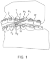
- FIG. 1 depicts a prior art example of an orthodontic appliance used for a brace system.
- a bracket having a wire clasp (C) is cemented to each tooth (T) and an alignment wire (W) is applied through each clasp (C), providing support for an orthodontic appliance (A), secured to the top and bottom wires at pivots (P1) and (P2). These pivots have an aperture (not shown) through which the wire (W) passes when the appliance (A) is installed.
- the depicted appliance (A) is a spring, which may facilitate lower jaw movement. When the appliance (A) must be changed, it is desirable to remove the appliance (A) quickly and easily, and without having to remove the other components.
- US-A-2006/046225 discloses an orthodontic device allows direct attachment to orthodontic wires.
- the device has clip members that permit direct clipping onto the orthodontic wires to thereby retain the device on the orthodontic wires.
- GB-A-2 575 488 discloses a device for securing articles to a surface.
- the device has an anchor pad for engaging with the surface, a cylindrical base on the anchor pad, and a screw cap rotatably mountable on the base via a screw mounting.
- the screw cap is moveable between an article receiving position and an article gripping position.
- US-A-2011575 discloses a stud for attachment to a tooth, the stud for attaching and detaching tooth band around the teeth of the user.
- a post for attaching to an alignment wire comprising: a cylindrical body having first end and an opposing second end, the body having a center axis and a radius; a bore coaxially disposed through the body from the first end to the second end; a pair of generally L-shaped locking elements attached to the second end, each of the locking elements comprising: a flange arm attached to and extending perpendicularly from the second end, the flange arm having a generally arcuate exterior surface coaxial and co-radial with the body, and an opposing planar interior surface; and a flange attached to and extending perpendicularly from the flange arm, the flange having an arcuate exterior surface coaxial and co-radial with the body, the arcuate exterior surface having opposing ends connected by a planar chord surface, and the flange having a planar surface distal the second end and an opposing surface proximal the second end; wherein each
- the alignment wire is adjacent each of the flange arm interior surfaces.
- each of the proximal surfaces of the flanges comprises a detent adjacent the each flange arm.
- each of the detents is sized and shaped to receive and retain an alignment wire.
- each of the detents is sized and shaped to inhibit the movement of an alignment wire retained in the detent.
- the bore is sized and shaped to receive a fastener.
- the bore is sized and shaped to receive a threaded fastener.
- the alignment wire when an alignment wire is captured in the locking recesses, the alignment wire intersects the center axis, and when a fastener is received in the bore, the fastener holds the alignment wire against the proximal surfaces of the flanges.
- the post further comprises an annular gripping element coaxial with the body and having a radius larger than the body such that the gripping element circumscribes the body, the gripping element truncated at opposing sides by two parallel chords.
- the truncated chords are sized and shaped to receive torque from an orthodontic wrench.
- a method of interfacing a post and an alignment wire comprising: providing an alignment wire; providing a fastener; providing a post comprising: a cylindrical body having first end and an opposing second end, the body having a center axis and a radius; a bore coaxially disposed through the body from the first end to the second end, the hollow interior bore sized and shaped to receive the fastener; a pair of generally L-shaped locking elements attached to the distal end, each of the locking elements comprising: a flange arm attached to and extending perpendicularly from the second end, the flange arm having a generally arcuate exterior surface coaxial and co-radial with the body, and an opposing planar interior surface; and a flange attached to and extending perpendicularly from the flange arm, the flange having an arcuate exterior surface coaxial and co-radial with the body, the arcuate exterior surface having opposing ends connected by a planar surface, and the
- the method further comprises: in the providing a post, the post further comprising an annular gripping element coaxial with the body and having a radius larger than the radius of the body such that the gripping element circumscribes the body, the gripping element truncated at opposing sides by two parallel chords; the rotating further comprises rotating the body by applying an orthodontic wrench to the truncated chords.
Landscapes
- Health & Medical Sciences (AREA)
- Oral & Maxillofacial Surgery (AREA)
- Dentistry (AREA)
- Epidemiology (AREA)
- Life Sciences & Earth Sciences (AREA)
- Animal Behavior & Ethology (AREA)
- General Health & Medical Sciences (AREA)
- Public Health (AREA)
- Veterinary Medicine (AREA)
- Dental Tools And Instruments Or Auxiliary Dental Instruments (AREA)
Description
- This application claims priority from
United States Utility Application No. 16/866,586 filed May 5, 2020 - This disclosure is related to the field of orthodontic appliances. In particular, it relates to a twist-lock pin and post system that facilitates quick and easy installation, adjustment, and removal.
- Orthodontics is a dentistry specialty focused on the treatment of medical conditions related to the placement and orientation of teeth. Human teeth often grow into misaligned positions and orientations, which can result in an unattractive, jagged appearance. Additionally, jaw misalignment can result in overbites, underbites, and other conditions. Serious cases can impact function and present negative health consequences. In severe instances, facial surgery may be required. However, most cases are addressed by mechanical correction using an orthodontic or dental appliance, known colloquially as "braces."
- Orthodontic braces are mechanical devices affixed to the teeth and tensioned to apply consistent pressure over a long period of time to gradually realign the teeth or jaw. Braces have a number of components. First, braces include a set of brackets, which are small squares bonded directly to the teeth, such as by using a dental bonding agent and/or by attaching an orthodontic band. The bonding agent is a strong adhesive suitable for exposure to the environment of the mouth. Orthodontic bands typically wrap around the tooth and provide an anchor for the brackets. In some applications, the patient may have brackets but no bands.
- Another significant component of dental braces is the guide wire, sometimes also known as an arch wire or an alignment wire. Such wires are usually anchored to the backmost teeth and attached to each bracket. The wire provides the movement path desired for correction. Many dental brace systems include other appliances, such as rubber bands, springs, and headgear, which can be used to apply additional pressure to facilitate alignment correction. The bracket/alignment wire components are typically connected directly to the teeth, and can then support other parts of the appliance, such as biasing springs or a Herbst appliance.
- It is often the case that, over the course of treatments, the brace system and certain appliances used therewith need to be partially or fully disassembled. This involves removing springs and other components mounted to the wire, disconnecting the wire, and, in some cases, possibly removing one or more of the brackets. This may be done, for example, to install a larger or smaller appliance, or for final finishing for tooth or jaw movement.
-
FIG. 1 depicts a prior art example of an orthodontic appliance used for a brace system. As depicted, a bracket having a wire clasp (C) is cemented to each tooth (T) and an alignment wire (W) is applied through each clasp (C), providing support for an orthodontic appliance (A), secured to the top and bottom wires at pivots (P1) and (P2). These pivots have an aperture (not shown) through which the wire (W) passes when the appliance (A) is installed. The depicted appliance (A) is a spring, which may facilitate lower jaw movement. When the appliance (A) must be changed, it is desirable to remove the appliance (A) quickly and easily, and without having to remove the other components. - However, structures which facilitate easy removal of the appliance (A) present difficulties because it is desirable that the appliance (A) only be removed by the orthodontist for therapeutic purposes. If the connection between the appliance (A) and the wire (W) is not firm enough, the appliance (A) may become unintentionally disconnected. This can result in injury to the patient or damage to the appliance (A). It is thus desirable to have a strong connection that is easy to intentionally remove, but hard to unintentionally remove.
-
US-A-2006/046225 discloses an orthodontic device allows direct attachment to orthodontic wires. The device has clip members that permit direct clipping onto the orthodontic wires to thereby retain the device on the orthodontic wires. -
GB-A-2 575 488 -
US-A-2011575 discloses a stud for attachment to a tooth, the stud for attaching and detaching tooth band around the teeth of the user. - The following is a summary of the invention in order to provide a basic understanding of some aspects of the invention. This summary is not intended to identify key or critical elements of the invention or to delineate the scope of the invention. The sole purpose of this section is to present some concepts of the invention in a simplified form as a prelude to the more detailed description that is presented later.
- Because of these and other problems in the art, described herein, among other things, is a post for attaching to an alignment wire comprising: a cylindrical body having first end and an opposing second end, the body having a center axis and a radius; a bore coaxially disposed through the body from the first end to the second end; a pair of generally L-shaped locking elements attached to the second end, each of the locking elements comprising: a flange arm attached to and extending perpendicularly from the second end, the flange arm having a generally arcuate exterior surface coaxial and co-radial with the body, and an opposing planar interior surface; and a flange attached to and extending perpendicularly from the flange arm, the flange having an arcuate exterior surface coaxial and co-radial with the body, the arcuate exterior surface having opposing ends connected by a planar chord surface, and the flange having a planar surface distal the second end and an opposing surface proximal the second end; wherein each of the flange arms is attached to the second end at opposing sides of the center axis; wherein the planar surfaces are in an opposing parallel configuration defining a center channel extending from the distal surfaces to the proximal surfaces of the flanges, the center channel perpendicular to and passing through the center axis; and wherein a gap between the second end of the body and each of the flange proximal surfaces defines a pair of opposing locking recesses having a first end in communication with the center channel and an opposing second end adjacent the interior surface of the each flange arm; and wherein, when an alignment wire is passed through the center channel, the alignment wire is disposed at the second end such that rotating the body causes the flanges to capture the alignment wire in the locking recesses.
- On an embodiment of the post, when an alignment wire is passed through the center channel and the body is rotated to cause the flanges to capture the alignment wire in the locking recesses, the alignment wire is adjacent each of the flange arm interior surfaces.
- In another embodiment of the post, each of the proximal surfaces of the flanges comprises a detent adjacent the each flange arm.
- In another embodiment of the post, each of the detents is sized and shaped to receive and retain an alignment wire.
- In another embodiment of the post, each of the detents is sized and shaped to inhibit the movement of an alignment wire retained in the detent.
- In another embodiment of the post, the bore is sized and shaped to receive a fastener.
- In another embodiment of the post, the bore is sized and shaped to receive a threaded fastener.
- In another embodiment of the post, when an alignment wire is captured in the locking recesses, the alignment wire intersects the center axis, and when a fastener is received in the bore, the fastener holds the alignment wire against the proximal surfaces of the flanges.
- In another embodiment of the post, the post further comprises an annular gripping element coaxial with the body and having a radius larger than the body such that the gripping element circumscribes the body, the gripping element truncated at opposing sides by two parallel chords.
- In another embodiment of the post, the truncated chords are sized and shaped to receive torque from an orthodontic wrench.
- Also described herein, among other things, is a method of interfacing a post and an alignment wire comprising: providing an alignment wire; providing a fastener; providing a post comprising: a cylindrical body having first end and an opposing second end, the body having a center axis and a radius; a bore coaxially disposed through the body from the first end to the second end, the hollow interior bore sized and shaped to receive the fastener; a pair of generally L-shaped locking elements attached to the distal end, each of the locking elements comprising: a flange arm attached to and extending perpendicularly from the second end, the flange arm having a generally arcuate exterior surface coaxial and co-radial with the body, and an opposing planar interior surface; and a flange attached to and extending perpendicularly from the flange arm, the flange having an arcuate exterior surface coaxial and co-radial with the body, the arcuate exterior surface having opposing ends connected by a planar surface, and the flange having a planar surface distal the second end and an opposing surface proximal the second end; wherein each of the flange arms is attached to the second end at opposing sides of the center axis; wherein the planar surfaces are in an opposing parallel configuration defining a center channel extending from the distal surfaces to the proximal surfaces of the flanges, the center channel perpendicular to and passing through the center axis; and wherein a gap between the second end of the body and each of the flange proximal surfaces defines a pair of opposing locking recesses having a first end in communication with the center channel and an opposing second end adjacent the interior surface of the each flange arm; passing the alignment wire through the center channel until the alignment wire is disposed at the second end; rotating the body to cause the flanges to capture the alignment wire in the locking recesses; and inserting the fastener through the bore until the fastener holds the alignment wire against the proximal surfaces of the flanges.
- In an embodiment of the method, the rotating further comprises rotating the body to cause the wire to be adjacent each of the flange arm interior surfaces.
- In another embodiment of the method, the method further comprises: in the providing a post, each of the proximal surfaces of the flanges comprises a detent adjacent the each flange arm; and the rotating further comprises rotating the body to cause the alignment wire to be received by each of the detents.
- In another embodiment of the method, the method further comprises: in the providing a post, the post further comprising an annular gripping element coaxial with the body and having a radius larger than the radius of the body such that the gripping element circumscribes the body, the gripping element truncated at opposing sides by two parallel chords; the rotating further comprises rotating the body by applying an orthodontic wrench to the truncated chords.
- In another embodiment of the method, the method further comprises: after the inserting the fastener, removing the fastener from the bore; after the rotating, counter-rotating the body until the alignment wire is not disposed in the locking recesses and is generally parallel with the channel; and removing the post from the alignment wire.
- Also described herein, among other things, is an orthodontic post and pin system comprising: a fastener; a post comprising: a cylindrical body having first end and an opposing second end, the body having a center axis and a radius; a bore coaxially disposed through the body from the first end to the second end and sized and shaped to receive the fastener; a pair of generally L-shaped locking elements attached to the distal end, each of the locking elements comprising: a flange arm attached to and extending perpendicularly from the second end, the flange arm having a generally arcuate exterior surface coaxial and co-radial with the body, and an opposing planar interior surface; and a flange attached to and extending perpendicularly from the flange arm, the flange having an arcuate exterior surface coaxial and co-radial with the body, the arcuate exterior surface having opposing ends connected by a planar surface, and the flange having a planar surface distal the second end and an opposing surface proximal the second end; wherein each of the flange arms is attached to the second end at opposing sides of the center axis; wherein the planar surfaces are in an opposing parallel configuration defining a center channel extending from the distal surfaces to the proximal surfaces of the flanges, the center channel perpendicular to and passing through the center axis; and wherein a gap between the second end of the body and each of the flange proximal surfaces defines a pair of opposing locking recesses having a first end in communication with the center channel and an opposing second end adjacent the interior surface of the each of the flange arms; wherein, when an alignment wire is passed through the center channel, the alignment wire is disposed at the second end such that rotating the body causes the flanges to capture the alignment wire in the locking recesses, and if the fastener is inserted through the center bore, the fastener holds the alignment wire against the proximal surfaces of the flanges.
-
-
FIG. 1 depicts an embodiment of a prior art dental appliance. -
FIG. 2 depicts an embodiment of a twist-lock orthodontic post from a top side perspective view. -
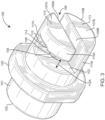
FIG. 3 depicts the embodiment ofFIG. 2 from a bottom side perspective view. -
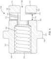
FIG. 4 provides a cutaway side view of the embodiment ofFIG. 2 . -
FIG. 5 provides an embodiment of a twist-lock post installed on a dental appliance. -
FIG. 6 provides a top side perspective view of an embodiment of an orthodontic post. -
FIG. 7 provides a back side perspective view of an embodiment of an orthodontic post. -
FIG. 8 provides a top elevation view of an embodiment of an orthodontic post. -
FIG. 9 provides a bottom elevation view of an embodiment of an orthodontic post. -
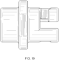
FIG. 10 provides a right side elevation view of an embodiment of an embodiment of an orthodotic post. -
FIG. 11 provides a left side elevation view of an orthodontic post. -
FIG. 12 provides a front elevation view of an embodiment of an orthodontic post. -
FIG. 13 provides a back elevation view of an embodiment of an orthodontic post. -
FIG. 14 provides a right side elevation cutaway view of an embodiment of an orthodontic post, the left side elevation cutaway view being a mirror image. - The following detailed description and disclosure illustrates by way of example and not by way of limitation. This description will clearly enable one skilled in the art to make and use the disclosed systems and methods, and describes several embodiments, adaptations, variations, alternatives and uses of the disclosed systems and methods. As various changes could be made in the above constructions without departing from the scope of the disclosures, it is intended that all matter contained in the description or shown in the accompanying drawings shall be interpreted as illustrative and not in a limiting sense.
- Described herein, among other things, is an orthodontic post and pin system for secure attachment of a dental appliance to an alignment wire, which also facilitates quick and easy removal and replacement. At a high level of generality, the system described herein uses a "twist-lock" dental post that is rotated onto, and counter-rotated off of, an alignment wire. The dental post includes structural elements to facilitate the twist-lock functionality, as well as structures for accepting a fastener to secure the alignment wire in place and inhibit unintentional or undesired dislodging.
-
FIG. 2 depicts an exemplary embodiment of a dental post as described herein. In the depicted embodiment, the post (100) is generally in the configuration of a cylinder. The depicted post (100) comprises a main body (101) having a first end (102) and an opposing second end (103). In the depicted embodiment, the first end (102) includes a receiving element, which has an aperture (104) providing access to a hollow interior bore (105). In the depicted embodiment, the hollow interior bore (105) is coaxial with the post (100) and extends axially from the outside surface of the first end (102) to the outside surface of the second end (103). The depicted hollow interior bore (105) is sized and shaped to accept a fastener, sometimes also referred to as a pin. In the depicted embodiment, the pin is a screw or threaded element, and, accordingly, the hollow interior bore (105) comprises corresponding threads around the interior circumference to accommodate the corresponding threads of the pin. By way of example, and not limitation. in an embodiment, the hollow interior bore (105) may be sized and shaped to accept the fastener described inU.S. Pat. No. D749,737 . This is not limiting, and in an alternative embodiment, a different configuration of fastener may be used. - In the depicted embodiment of
FIG. 2 , the hollow interior bore (105) has a variable radius, being narrower along the main length and having a wider radius at the first end (102). This facilitates the use of a pin having a wider head than body, which may be screwed into the hollow interior bore (105), recessing the head within the post (100) interior volume and allowing for a flush installation. -
FIG. 3 depicts the embodiment ofFIG. 2 from the bottom, showing the "twist-lock" structure. In the depicted embodiment ofFIG. 3 , the second end (103) can be seen, including a corresponding aperture (106) for the hollow interior bore (105). As described in further detail elsewhere herein, this facilitates the use of the fastener to pin the alignment wire in place. - As shown in the depicted embodiment of
FIG. 3 , "twist-lock" elements are affixed to the second end (103). In the depicted embodiment, the twist-lock. elements comprise a pair of opposing flanges (107). The depicted flanges (107) are disposed so as to create a central channel (108) formed by opposing faces (109) of the flanges (107). These faces (109) are generally planar surfaces opposing one another in a parallel arrangement. In the depicted embodiment, the channel (108) extends perpendicularly with respect to the main axis of the post (100), and intersects the center axis of the post (100). The depicted flanges (109) are in the configuration of geometric segments of the cylindrical body (101), and have an opposing exterior, arcuate surface (110) connected at the ends by a planar chord surface. These arcuate surfaces (110) are sized, shaped, and dimensioned so as to create the effect of a continuous cylindrical form with the main body (101). That is, they are coaxial and co-radial with the main body (101). In the depicted embodiment, the distal surfaces of the flanges (113) are generally co-planar. This has the overall effect of causing a combination of the main body (101) and the twist-lock elements to appear as a cylinder with the channel (108) and locking recess (112) removed therefrom. - The channel (108) is sized, shaped, and dimensioned to facilitate the passage of an alignment wire. Thus, the thickness of the flanges (107) will be determined generally based upon the dimensions of the alignment wire that will pass between the faces (109) defining the channel (108).
- As may be seen in the depicted embodiment of
FIG. 3 , each of the flanges (107) is attached to the second end (103) by a flange arm (111). The depicted flange arms (111) are generally perpendicularly attached to the second end (103) at opposing positions across the center axis. The depicted flanges (107) are generally attached perpendicularly to their respective flange arms (111). This causes the flanges (107) and flange arms (111) to each have the general configuration of an "L." The depicted flange arms (111) are also co-radial and coaxial with the main body (101). - As can be seen in the depicted embodiment, the depicted flanges (107) have generally the same configuration, but are disposed on opposing ends of the second end (103), causing each (107) to project from its respective flange arm (111) in opposing directions. This in turn causes each of the flanges (107) to define a locking recess (112) defined by the distance between the outside surface of the second end (103) and the proximal surface of each flange (107) the interior surfaces of the flange arms (111) at one end, and being in communication with the channel (108) of the opposing end. The locking recesses (112) are generally sized, shaped, and dimensioned to accept the passage of an alignment wire to facilitate the "twist-lock" function described elsewhere herein.
- In the depicted embodiment of
FIG 3 , each of the flanges (107) includes a detent (114) disposed along the proximal surface of the flange (113). This detent (114) provides for a wider gap near the interior surface (115) of the flange arm (111) than at the confluence of the locking recess (112)and the channel (108). This has the effect of providing a physical barrier to inhibit unintentional movement of an alignment wire. - To install and use the depicted post (100), the post (100) is placed over an alignment wire by passing the alignment wire through the channel (108) until it is at or near the second end (103) of the main body (101). This arrangement is depicted in FlG. 5. Next, the post (100) is rotated clockwise, causing the flanges (107) to rotate in opposing directions and pass beneath the alignment wire, which is then captured in the locking recess (112). Rotation continues until the adjustment is adjacent to the interior surfaces (115). In this configuration, the detent (114) assists to hold the wire in place. As can be seen in the depicted embodiment, in this configuration, the alignment wire is generally perpendicular to the major axis of the post (100) and intersects the central axis of the post (100).
- Next, a pin may be screwed into the post (100) from the first end (102). As the pin is screwed in, its distal end exits the aperture (106) in the second end (103), and contacts the wire. The pin is then tightened to hold the wire in place from the top. Once installed, the flanges (113) inhibit the wire from becoming disconnected from the post (100), and the pressure from the pin holds the wire against the proximal surface of the flanges (107). To remove the post (100), this process is simply reversed. The pin is counter-rotated to unscrew it from the post (100), which releases the pressure on the wire. The post (100) may then be counter-rotated to cause the channel (108) to become parallel with the wire, and the post (100) may then be simply lifted off the alignment wire.
- In an embodiment, the post (100) may comprise additional elements, such as, but not necessarily limited to, a gripping element (120) configured to facilitate twisting. Applying torque to a small cylindrical object can be difficult due to slippage and low contact surface area. To overcome this, the depicted embodiment includes a generally annular gripping element (120) which is generally coaxial with the post (100), but which has a larger radius. In the depicted embodiment, the gripping element (120) includes two opposing chords (121) arranged generally in parallel with each other and providing flat gripping services for a fastening tool.
- Throughout this disclosure, geometric terms, and relative qualifies such as "generally," "about," and "approximately" may be used, such as, but not necessarily limited to, with respect to shapes, sizes, dimensions, angles, and distances. One of ordinary skill in the art will understand that, in the context of this disclosure, these terms are used to describe an attempt by a person of ordinary skill in the art to cause the component in question to be recognizable as the term in question. By way of example and not limitation, components described as being "generally coplanar" will be recognized by one of ordinary skill in the art to not be actually coplanar in a strict geometric sense because a "plane" is a purely geometric construct that does not actually exist and no component is truly "planer" nor are two components ever truly coplanar.
- The use of geometric descriptions herein should be understood as encompassing a reasonable range of variations from the literal geometric meaning, and includes, but is not necessarily limited to, variations resulting from: manufacturing tolerances causing shape variations, deformations, and defects, natural imperfections; non-uniform thermal expansion; natural wear; and other deformations. Further, there exists for every object a level of magnification at which geometric descriptors no longer apply due to the nature of matter. One of ordinary skill in the art will understand how to apply geometric and relative terms in view of these and other context-specific considerations. Also, the use of the conjunctive and disjunctive should not necessarily be construed as limiting, and the conjunctive may include the disjunctive, and vice versa.
Claims (15)
- A post (100) for attaching to an alignment wire whereby said post comprises:a cylindrical body (101) having first end (102) and an opposing second end (103), said body having a center axis and a radius;a bore (105) coaxially disposed through said body (101) from said first end (102) to said second end (103);a pair of generally L-shaped locking elements (107) attached to said second end (103), each of said locking elements comprising:a flange arm (111) attached to and extending perpendicularly from said second end (103), said flange arm having a generally arcuate exterior surface coaxial and co-radial with said body (101), and an opposing planar interior surface (115); anda flange (113) attached to and extending perpendicularly from said flange arm (111), said flange (113) having an arcuate exterior surface (110) coaxial and co-radial with said body (101), said arcuate exterior surface having opposing ends connected by a planar surface 109), and said flange (113) having a planar surface distal said second end (103) and an opposing surface proximal said second end;wherein each of said flange arms (111) is attached to said second end (103) at opposing sides of said center axis;wherein said planar surfaces 109) are in an opposing parallel configuration defining a center channel (108) extending from said distal surfaces to said proximal surfaces of said flanges, said center channel (108) perpendicular to and passing through said center axis; andwherein a gap (112) between said second end (103) of said body (101) and each of said flange proximal surfaces defines a pair of opposing locking recesses (112) having a first end in communication with said center channel (104) and an opposing second end adjacent said interior surface of said each flange arm (111);wherein, when an alignment wire is passed through said center channel (108), said alignment wire is disposed at said second end (103) such that rotating said body (101) causes said flanges (113) to capture said alignment wire in said locking recesses (112).
- The post of claim 1, wherein when an alignment wire is passed through said center channel (108) and said body (101) is rotated to cause said flanges (113) to capture said alignment wire in said locking recesses (112), said alignment wire is adjacent each of said flange arm interior surfaces (115).
- The post of claim 2, wherein each of said proximal surfaces of said flanges (113) comprises a detent (114) adjacent said each flange arm (111);
optionally wherein each of said detents (114) is sized and shaped to receive and retain an alignment wire. - The post of claim 3, wherein each of said detents (114) is sized and shaped to inhibit the movement of an alignment wire retained in said detent.
- The post of claim 1, wherein said bore (105) is sized and shaped to receive a fastener.
- The post of claim 5, wherein said bore (105) is sized and shaped to receive a threaded fastener.
- The post of claim 5, wherein when an alignment wire is captured in said locking recesses (112), said alignment wire intersects said center axis, and when a fastener is received in said bore (105), said fastener holds said alignment wire against said proximal surfaces of said flanges (113).
- The post of claim 1, further comprising an annular gripping element (120) coaxial with said body (101) and having a radius larger than said body such that said gripping element circumscribes said body, said gripping element truncated at opposing sides by two parallel surfaces (121).
- The post of claim 8, wherein said truncated surfaces (121) are sized and shaped to receive torque from an orthodontic wrench.
- A method of interfacing a post and an alignment wire comprising:providing an alignment wire (A);providing a fastener;providing a post (100) comprising:a cylindrical body (101) having first end (102) and an opposing second end (103), said body (101) having a center axis and a radius;a bore (105) coaxially disposed through said body (101) from said first end (102) to said second end (103), said bore sized and shaped to receive said fastener;a pair of generally L-shaped locking elements (107) attached to said distal end, each of said locking elements comprising:a flange arm (111) attached to and extending perpendicularly from said second end (103), said flange arm having a generally arcuate exterior surface coaxial and co-radial with said body (101), and an opposing planar interior surface (115); anda flange (113) attached to and extending perpendicularly from said flange arm (111), said flange (113) having an arcuate exterior surface (110) coaxial and co-radial with said body (101), said arcuate exterior surface having opposing ends connected by a planar surface (107, 109), and said flange (113) having a planar surface distal said second end (103) and an opposing surface proximal said second end;wherein each of said flange arms (111) is attached to said second end (103) at opposing sides of said center axis;wherein said planar surfaces 109) are in an opposing parallel configuration defining a center channel (108) extending from said distal surfaces to said proximal surfaces of said flanges, said center channel (108) perpendicular to and passing through said center axis; andwherein a gap (112) between said second end (103) of said body (101) and each of said flange proximal surfaces defines a pair of opposing locking recesses (112) having a first end in communication with said center channel (104) and an opposing second end adjacent said interior surface of said each flange arm;passing said alignment wire (A) through said center channel (104) until said alignment wire is disposed at said second end (103);rotating said body (101) to cause said flanges (107) to capture said alignment wire in said locking recesses; andinserting said fastener through said bore (105) until said fastener holds said alignment wire against said proximal surfaces of said flanges (113).
- The method of claim 10, said rotating further comprises rotating said body (101) to cause said wire to be adjacent each of said flange arm interior surfaces.
- The method of claim 11, further comprising:in said providing a post (100), each of said proximal surfaces of said flanges comprises a detent (113) adjacent said each flange arm (111); andsaid rotating further comprises rotating said body (101) to cause said alignment wire to be received by each of said detents (114).
- The method of claim 10, further comprising:in said providing a post, said post further comprising an annular gripping element (120) coaxial with said body (101) and having a radius larger than said radius of said body such that said gripping element circumscribes said body, said gripping element truncated at opposing sides by two parallel surfaces (121);said rotating further comprises rotating said body (101) by applying an orthodontic wrench to said parallel surfaces (121).
- The method of claim 10, further comprising:after said inserting said fastener, removing said fastener from said bore (105);after said rotating, counter-rotating said body (101) until said alignment wire is not disposed in said locking recesses and is generally parallel with said channel; andremoving said post from said alignment wire.
- An orthodontic post and pin system comprising:a fastener;a post (100) comprising the features of any of claims 1-9, wherein if said fastener is inserted through said bore (105), said fastener holds said alignment wire (A) against said proximal surfaces of said flanges.
Applications Claiming Priority (2)
| Application Number | Priority Date | Filing Date | Title |
|---|---|---|---|
| US16/866,586 US11273013B2 (en) | 2020-05-05 | 2020-05-05 | Twist-lock orthodontic post |
| PCT/US2021/030893 WO2021226239A1 (en) | 2020-05-05 | 2021-05-05 | Twist-lock orthodontic post |
Publications (3)
| Publication Number | Publication Date |
|---|---|
| EP4146119A1 EP4146119A1 (en) | 2023-03-15 |
| EP4146119A4 EP4146119A4 (en) | 2023-08-23 |
| EP4146119B1 true EP4146119B1 (en) | 2025-06-25 |
Family
ID=78412051
Family Applications (1)
| Application Number | Title | Priority Date | Filing Date |
|---|---|---|---|
| EP21799698.2A Active EP4146119B1 (en) | 2020-05-05 | 2021-05-05 | Twist-lock orthodontic post |
Country Status (3)
| Country | Link |
|---|---|
| US (3) | US11273013B2 (en) |
| EP (1) | EP4146119B1 (en) |
| WO (1) | WO2021226239A1 (en) |
Families Citing this family (1)
| Publication number | Priority date | Publication date | Assignee | Title |
|---|---|---|---|---|
| US11273013B2 (en) * | 2020-05-05 | 2022-03-15 | Ortho Solutions, LC | Twist-lock orthodontic post |
Family Cites Families (54)
| Publication number | Priority date | Publication date | Assignee | Title |
|---|---|---|---|---|
| US2011575A (en) | 1933-01-28 | 1935-08-20 | James W Ford | Orthodontic appliance |
| US2104192A (en) * | 1935-08-19 | 1938-01-04 | James W Ford | Orthodontic appliance |
| US2926422A (en) * | 1959-01-06 | 1960-03-01 | Wallshein Melvin | Orthodontic brackets |
| US3238619A (en) | 1963-04-29 | 1966-03-08 | Rocky Mouutain Dental Products | Arch wire locking device for orthodontic bracket |
| US3798773A (en) * | 1972-05-08 | 1974-03-26 | M Northcutt | Device for improving the alignment of the upper and lower sets of teeth with each other |
| DE3423106C2 (en) | 1983-07-06 | 1985-09-19 | OBO Bettermann oHG, 5750 Menden | Spacers for electrical conductors, in particular for lightning protection conductors |
| NO891420D0 (en) * | 1989-04-06 | 1989-04-06 | Swadesh Kumar | ORTHODONTIC HANGING. |
| US6402510B1 (en) | 1998-04-23 | 2002-06-11 | Michael O. Williams | Buccal tipping-resistant mandibular and maxillary arch expander |
| US20110287378A1 (en) | 2002-10-29 | 2011-11-24 | Rmo, Inc. | Orthodontic appliance with encoded information formed in the base |
| ITPD20030278A1 (en) * | 2003-11-20 | 2005-05-21 | Valter Vigolo | SELF-LOCKING ORTHODONTIC ATTACK AND METHOD |
| US7070410B2 (en) * | 2004-09-02 | 2006-07-04 | Cacchiotti Dino A | Orthodontic device for attachment to orthodontic wire |
| ITME20040007A1 (en) | 2004-09-16 | 2004-12-16 | Riccardo Nucera | ORTHODONTIC ATTACHMENT WITH SCREW. |
| DE102004046414B4 (en) * | 2004-09-24 | 2006-10-12 | Stryker Leibinger Gmbh & Co. Kg | Surgical anchoring device |
| FR2882918B1 (en) * | 2005-03-14 | 2008-02-22 | Charles Clor | ORTHODONTIC CORRECTION DEVICE |
| DE102005016736A1 (en) | 2005-04-11 | 2006-10-12 | Bredent Dentalgeräte u. Materialien Fach- u. Organisationsberatung Peter Brehm | Orthopaedic dental frame for moving the lower mandible forward has upper and lower links to connect telescopic bar to upper and lower jaws via ball joints |
| US20060234180A1 (en) * | 2005-04-18 | 2006-10-19 | Specialty Appliance Works, Inc. | Herbst orthodontic appliance with improved pivot |
| US8979528B2 (en) | 2006-09-07 | 2015-03-17 | Rmo, Inc. | Customized orthodontic appliance method and system |
| DE102007039761B4 (en) | 2007-08-22 | 2012-06-06 | Enrico Pasin | Orthodontic appliance and fastening device for fastening an orthodontic appliance |
| IT1392605B1 (en) * | 2008-12-31 | 2012-03-09 | Hdc S R L | FIXING DEVICE FOR ORTHODONTIC APPLIANCES |
| WO2010120580A1 (en) * | 2009-04-14 | 2010-10-21 | 3M Innovative Properties Company | Orthodontic connector providing controlled engagement with an orthodontic wire |
| US8257080B2 (en) | 2009-05-05 | 2012-09-04 | 3M Innovative Properties Company | Low profile orthodontic bite corrector |
| US8162660B2 (en) | 2009-11-20 | 2012-04-24 | Robert T Rudman | Rotating clip orthodontic bracket |
| FR2962897B1 (en) | 2010-07-20 | 2013-12-13 | Dominico Klein | ORTHOSIS COMPRISING A SUPERIOR GUTTER AND A LOWER GUTTER, AND CONNECTING MEANS ADJUSTABLE IN POSITION |
| US20130280670A1 (en) * | 2010-09-22 | 2013-10-24 | Rmo, Inc. | Orthodontic Appliance and Method for Class II and Class III Malocclusion and Dental Asymmetric Correction |
| US20170296306A1 (en) * | 2010-09-22 | 2017-10-19 | Rmo, Inc. | Orthodontic appliance and method for class ii and class iii malocclusion and dental asymmetric correction |
| US20140045137A1 (en) | 2010-11-25 | 2014-02-13 | José Enrique SOLANO REINA | Orthodontic archwire bracket |
| US9237941B2 (en) * | 2011-12-22 | 2016-01-19 | Andrew Hayes | Orthodontic appliance and system |
| US20140020691A1 (en) | 2012-07-18 | 2014-01-23 | Rest Assured Technologies | Oral appliance for treatment of medical conditions such as obstructive sleep apnea and snoring and for improving athletic performance and method of optimizing same |
| EP3545901B1 (en) | 2012-10-30 | 2021-03-03 | University of Southern California | Orthodontic appliance with snap fitted, non-sliding archwire |
| US9393085B2 (en) * | 2012-12-07 | 2016-07-19 | Ormco Corporation | Connector for coupling an orthodontic appliance to a patient and associated methods |
| US20140224257A1 (en) | 2013-02-12 | 2014-08-14 | Mark Abramson | Adjustable telescopic hinge system for relative positioning of the upper and lower jaw |
| RU2664158C2 (en) | 2013-06-14 | 2018-08-15 | Ормко Корпорейшн | Self-ligating orthodontic bracket with rotatable closure member |
| US10456219B2 (en) * | 2014-01-09 | 2019-10-29 | Ortho Solutions, LC | Orthodonic post and pin assembly |
| USD848001S1 (en) * | 2016-10-05 | 2019-05-07 | OrthoSolutions, LC | Orthodontic post and pin assembly |
| USD749737S1 (en) * | 2014-01-09 | 2016-02-16 | Ortho Solutions, LC | Hybrid screw for orthodontic appliance |
| US9827138B2 (en) | 2014-01-27 | 2017-11-28 | Bruce W. Hultgren | Fabrication of maxillofacial splints |
| US9901420B2 (en) | 2014-02-25 | 2018-02-27 | Ormco Corporation | Orthodontic appliances including ferromagnetic shape memory alloys and methods of orthodontic treatment using same |
| US10716646B2 (en) * | 2014-03-13 | 2020-07-21 | Terry G. Dischinger | Method and apparatus for treating malocclusions and teeth alignment |
| CA2950063C (en) | 2014-07-11 | 2022-07-12 | Cooper Technologies Company | Pipe restraint |
| US9987107B2 (en) * | 2014-10-10 | 2018-06-05 | Ortho Solutions, LC | Mandibular repositioning device |
| US20160175072A1 (en) | 2014-12-19 | 2016-06-23 | Ormco Corporation | Self-ligating orthodontic bracket with rotatable closure member |
| US20170000588A1 (en) | 2015-07-01 | 2017-01-05 | Ormco Corporation | Self-ligating orthodontic bracket with an external rotatable closure member |
| CN108348306B (en) | 2015-11-02 | 2021-01-15 | 3M创新有限公司 | Orthodontic appliance with continuous shape memory |
| EP3527177A4 (en) | 2016-10-17 | 2020-10-14 | Mitsui Chemicals, Inc. | Dental coupling member, mouthpiece, and orthodontic tool |
| US10368962B2 (en) | 2016-11-21 | 2019-08-06 | James Joseph Jasper | Method and apparatus for orthodontic corrections |
| ES2957272T3 (en) | 2017-05-02 | 2024-01-16 | Tp Orthodontics Inc | Orthodontic bracket that has fixed ligating tabs |
| US11224500B2 (en) | 2018-03-14 | 2022-01-18 | James R. Glidewell Dental Ceramics, Inc. | Oral device, manufacturing apparatus and methods of making the same |
| US20210186663A1 (en) | 2018-06-15 | 2021-06-24 | 3M Innovative Properties Company | Orthodontic Appliance for Malocclusion Correction |
| GB2575488A (en) | 2018-07-12 | 2020-01-15 | Univ Limerick | A securement device |
| CN210114519U (en) * | 2019-02-27 | 2020-02-28 | 浙江普特医疗器械有限公司 | Annular double sliding cover double bearing self-locking bracket |
| US11786339B2 (en) | 2019-11-11 | 2023-10-17 | Smylio Inc. | Systems and methods for customizing oral appliance appearance |
| USD940878S1 (en) * | 2020-05-05 | 2022-01-11 | Ortho Solutions, LC | Orthodontic post |
| US11273013B2 (en) * | 2020-05-05 | 2022-03-15 | Ortho Solutions, LC | Twist-lock orthodontic post |
| CN112545687B (en) | 2020-12-02 | 2022-06-28 | 哈尔滨工业大学 | Double pressure sleeve guide rod compression spring dental appliance |
-
2020
- 2020-05-05 US US16/866,586 patent/US11273013B2/en active Active
-
2021
- 2021-05-05 EP EP21799698.2A patent/EP4146119B1/en active Active
- 2021-05-05 WO PCT/US2021/030893 patent/WO2021226239A1/en not_active Ceased
-
2022
- 2022-03-11 US US17/692,968 patent/US11826222B2/en active Active
-
2023
- 2023-11-08 US US18/504,903 patent/US12268572B2/en active Active
Also Published As
| Publication number | Publication date |
|---|---|
| EP4146119A1 (en) | 2023-03-15 |
| WO2021226239A1 (en) | 2021-11-11 |
| US20240074837A1 (en) | 2024-03-07 |
| US20210346128A1 (en) | 2021-11-11 |
| EP4146119A4 (en) | 2023-08-23 |
| US11826222B2 (en) | 2023-11-28 |
| US20220233278A1 (en) | 2022-07-28 |
| US11273013B2 (en) | 2022-03-15 |
| US12268572B2 (en) | 2025-04-08 |
Similar Documents
| Publication | Publication Date | Title |
|---|---|---|
| JP3471805B2 (en) | Orthodontic appliance | |
| US20120070797A1 (en) | Orthodontic Appliance and Method for Class II and Class III Malocclusion and Dental Asymmetric Correction | |
| ES2959932T3 (en) | Orthodontic holding device | |
| US11654000B2 (en) | Anteroposterior correction devices | |
| US9237941B2 (en) | Orthodontic appliance and system | |
| US20090105547A1 (en) | Adjustable Retractor Blade | |
| US7387633B2 (en) | Cranial flap fixation system and method | |
| US20130280670A1 (en) | Orthodontic Appliance and Method for Class II and Class III Malocclusion and Dental Asymmetric Correction | |
| US9393085B2 (en) | Connector for coupling an orthodontic appliance to a patient and associated methods | |
| US20050227197A1 (en) | Screw device for orthodontic treatment | |
| US5328364A (en) | Dental clamp | |
| EP3572031B1 (en) | Base member for orthodontic implant device | |
| US20170296306A1 (en) | Orthodontic appliance and method for class ii and class iii malocclusion and dental asymmetric correction | |
| JP3264924B2 (en) | Disposable dental matrix holding clamp | |
| US12318262B2 (en) | Force applying device for orthodontic treatment | |
| US12268572B2 (en) | Twist-lock orthodontic post | |
| WO2008045906A2 (en) | Orthodontic eyelet with crimpable portions and related methods | |
| US3497954A (en) | Bypass clamp for orthodontic bracket | |
| US20220087780A1 (en) | Archwire hooks, stops, and methods of using same | |
| US20150250567A1 (en) | Orthodontic anchor screw device | |
| EP4454599A1 (en) | Bondable orthodontic post and alignment system | |
| KR20220033936A (en) | Impalnt assembly | |
| WO2017207741A1 (en) | Connection device between a dental appliance and its anchorage |
Legal Events
| Date | Code | Title | Description |
|---|---|---|---|
| STAA | Information on the status of an ep patent application or granted ep patent |
Free format text: STATUS: THE INTERNATIONAL PUBLICATION HAS BEEN MADE |
|
| PUAI | Public reference made under article 153(3) epc to a published international application that has entered the european phase |
Free format text: ORIGINAL CODE: 0009012 |
|
| STAA | Information on the status of an ep patent application or granted ep patent |
Free format text: STATUS: REQUEST FOR EXAMINATION WAS MADE |
|
| 17P | Request for examination filed |
Effective date: 20221202 |
|
| AK | Designated contracting states |
Kind code of ref document: A1 Designated state(s): AL AT BE BG CH CY CZ DE DK EE ES FI FR GB GR HR HU IE IS IT LI LT LU LV MC MK MT NL NO PL PT RO RS SE SI SK SM TR |
|
| RAP3 | Party data changed (applicant data changed or rights of an application transferred) |
Owner name: ORTHO SOLUTIONS, LC DBA DYNAFLEX |
|
| P01 | Opt-out of the competence of the unified patent court (upc) registered |
Effective date: 20230614 |
|
| DAV | Request for validation of the european patent (deleted) | ||
| DAX | Request for extension of the european patent (deleted) | ||
| A4 | Supplementary search report drawn up and despatched |
Effective date: 20230721 |
|
| RIC1 | Information provided on ipc code assigned before grant |
Ipc: A61C 7/36 20060101ALI20230717BHEP Ipc: A61C 7/22 20060101ALI20230717BHEP Ipc: A61C 7/34 20060101AFI20230717BHEP |
|
| GRAP | Despatch of communication of intention to grant a patent |
Free format text: ORIGINAL CODE: EPIDOSNIGR1 |
|
| STAA | Information on the status of an ep patent application or granted ep patent |
Free format text: STATUS: GRANT OF PATENT IS INTENDED |
|
| INTG | Intention to grant announced |
Effective date: 20241223 |
|
| GRAS | Grant fee paid |
Free format text: ORIGINAL CODE: EPIDOSNIGR3 |
|
| GRAA | (expected) grant |
Free format text: ORIGINAL CODE: 0009210 |
|
| STAA | Information on the status of an ep patent application or granted ep patent |
Free format text: STATUS: THE PATENT HAS BEEN GRANTED |
|
| AK | Designated contracting states |
Kind code of ref document: B1 Designated state(s): AL AT BE BG CH CY CZ DE DK EE ES FI FR GB GR HR HU IE IS IT LI LT LU LV MC MK MT NL NO PL PT RO RS SE SI SK SM TR |
|
| REG | Reference to a national code |
Ref country code: GB Ref legal event code: FG4D |
|
| REG | Reference to a national code |
Ref country code: CH Ref legal event code: EP |
|
| REG | Reference to a national code |
Ref country code: CH Ref legal event code: EP |
|
| REG | Reference to a national code |
Ref country code: IE Ref legal event code: FG4D |
|
| REG | Reference to a national code |
Ref country code: DE Ref legal event code: R096 Ref document number: 602021032981 Country of ref document: DE |
|
| PG25 | Lapsed in a contracting state [announced via postgrant information from national office to epo] |
Ref country code: FI Free format text: LAPSE BECAUSE OF FAILURE TO SUBMIT A TRANSLATION OF THE DESCRIPTION OR TO PAY THE FEE WITHIN THE PRESCRIBED TIME-LIMIT Effective date: 20250625 |
|
| REG | Reference to a national code |
Ref country code: LT Ref legal event code: MG9D |
|
| PG25 | Lapsed in a contracting state [announced via postgrant information from national office to epo] |
Ref country code: NO Free format text: LAPSE BECAUSE OF FAILURE TO SUBMIT A TRANSLATION OF THE DESCRIPTION OR TO PAY THE FEE WITHIN THE PRESCRIBED TIME-LIMIT Effective date: 20250925 Ref country code: GR Free format text: LAPSE BECAUSE OF FAILURE TO SUBMIT A TRANSLATION OF THE DESCRIPTION OR TO PAY THE FEE WITHIN THE PRESCRIBED TIME-LIMIT Effective date: 20250926 |
|
| PG25 | Lapsed in a contracting state [announced via postgrant information from national office to epo] |
Ref country code: BG Free format text: LAPSE BECAUSE OF FAILURE TO SUBMIT A TRANSLATION OF THE DESCRIPTION OR TO PAY THE FEE WITHIN THE PRESCRIBED TIME-LIMIT Effective date: 20250625 |
|
| PG25 | Lapsed in a contracting state [announced via postgrant information from national office to epo] |
Ref country code: HR Free format text: LAPSE BECAUSE OF FAILURE TO SUBMIT A TRANSLATION OF THE DESCRIPTION OR TO PAY THE FEE WITHIN THE PRESCRIBED TIME-LIMIT Effective date: 20250625 |
|
| PG25 | Lapsed in a contracting state [announced via postgrant information from national office to epo] |
Ref country code: RS Free format text: LAPSE BECAUSE OF FAILURE TO SUBMIT A TRANSLATION OF THE DESCRIPTION OR TO PAY THE FEE WITHIN THE PRESCRIBED TIME-LIMIT Effective date: 20250925 |
|
| PG25 | Lapsed in a contracting state [announced via postgrant information from national office to epo] |
Ref country code: LV Free format text: LAPSE BECAUSE OF FAILURE TO SUBMIT A TRANSLATION OF THE DESCRIPTION OR TO PAY THE FEE WITHIN THE PRESCRIBED TIME-LIMIT Effective date: 20250625 |
|
| REG | Reference to a national code |
Ref country code: NL Ref legal event code: MP Effective date: 20250625 |
|
| PG25 | Lapsed in a contracting state [announced via postgrant information from national office to epo] |
Ref country code: NL Free format text: LAPSE BECAUSE OF FAILURE TO SUBMIT A TRANSLATION OF THE DESCRIPTION OR TO PAY THE FEE WITHIN THE PRESCRIBED TIME-LIMIT Effective date: 20250625 |
|
| PG25 | Lapsed in a contracting state [announced via postgrant information from national office to epo] |
Ref country code: PT Free format text: LAPSE BECAUSE OF FAILURE TO SUBMIT A TRANSLATION OF THE DESCRIPTION OR TO PAY THE FEE WITHIN THE PRESCRIBED TIME-LIMIT Effective date: 20251027 |
|
| REG | Reference to a national code |
Ref country code: AT Ref legal event code: MK05 Ref document number: 1805674 Country of ref document: AT Kind code of ref document: T Effective date: 20250625 |
|
| PG25 | Lapsed in a contracting state [announced via postgrant information from national office to epo] |
Ref country code: IS Free format text: LAPSE BECAUSE OF FAILURE TO SUBMIT A TRANSLATION OF THE DESCRIPTION OR TO PAY THE FEE WITHIN THE PRESCRIBED TIME-LIMIT Effective date: 20251025 |
|
| PG25 | Lapsed in a contracting state [announced via postgrant information from national office to epo] |
Ref country code: AT Free format text: LAPSE BECAUSE OF FAILURE TO SUBMIT A TRANSLATION OF THE DESCRIPTION OR TO PAY THE FEE WITHIN THE PRESCRIBED TIME-LIMIT Effective date: 20250625 Ref country code: SM Free format text: LAPSE BECAUSE OF FAILURE TO SUBMIT A TRANSLATION OF THE DESCRIPTION OR TO PAY THE FEE WITHIN THE PRESCRIBED TIME-LIMIT Effective date: 20250625 |
|
| PG25 | Lapsed in a contracting state [announced via postgrant information from national office to epo] |
Ref country code: CZ Free format text: LAPSE BECAUSE OF FAILURE TO SUBMIT A TRANSLATION OF THE DESCRIPTION OR TO PAY THE FEE WITHIN THE PRESCRIBED TIME-LIMIT Effective date: 20250625 |
|
| PG25 | Lapsed in a contracting state [announced via postgrant information from national office to epo] |
Ref country code: PL Free format text: LAPSE BECAUSE OF FAILURE TO SUBMIT A TRANSLATION OF THE DESCRIPTION OR TO PAY THE FEE WITHIN THE PRESCRIBED TIME-LIMIT Effective date: 20250625 |
|
| PG25 | Lapsed in a contracting state [announced via postgrant information from national office to epo] |
Ref country code: EE Free format text: LAPSE BECAUSE OF FAILURE TO SUBMIT A TRANSLATION OF THE DESCRIPTION OR TO PAY THE FEE WITHIN THE PRESCRIBED TIME-LIMIT Effective date: 20250625 |
|
| PG25 | Lapsed in a contracting state [announced via postgrant information from national office to epo] |
Ref country code: SK Free format text: LAPSE BECAUSE OF FAILURE TO SUBMIT A TRANSLATION OF THE DESCRIPTION OR TO PAY THE FEE WITHIN THE PRESCRIBED TIME-LIMIT Effective date: 20250625 |
|
| PG25 | Lapsed in a contracting state [announced via postgrant information from national office to epo] |
Ref country code: ES Free format text: LAPSE BECAUSE OF FAILURE TO SUBMIT A TRANSLATION OF THE DESCRIPTION OR TO PAY THE FEE WITHIN THE PRESCRIBED TIME-LIMIT Effective date: 20250625 |
|
| PG25 | Lapsed in a contracting state [announced via postgrant information from national office to epo] |
Ref country code: DK Free format text: LAPSE BECAUSE OF FAILURE TO SUBMIT A TRANSLATION OF THE DESCRIPTION OR TO PAY THE FEE WITHIN THE PRESCRIBED TIME-LIMIT Effective date: 20250625 |
|
| PG25 | Lapsed in a contracting state [announced via postgrant information from national office to epo] |
Ref country code: IT Free format text: LAPSE BECAUSE OF FAILURE TO SUBMIT A TRANSLATION OF THE DESCRIPTION OR TO PAY THE FEE WITHIN THE PRESCRIBED TIME-LIMIT Effective date: 20250625 |
|
| PLBE | No opposition filed within time limit |
Free format text: ORIGINAL CODE: 0009261 |
|
| STAA | Information on the status of an ep patent application or granted ep patent |
Free format text: STATUS: NO OPPOSITION FILED WITHIN TIME LIMIT |
|
| REG | Reference to a national code |
Ref country code: CH Ref legal event code: L10 Free format text: ST27 STATUS EVENT CODE: U-0-0-L10-L00 (AS PROVIDED BY THE NATIONAL OFFICE) Effective date: 20260507 |