EP4145852A1 - Electronic device - Google Patents
Electronic device Download PDFInfo
- Publication number
- EP4145852A1 EP4145852A1 EP21797140.7A EP21797140A EP4145852A1 EP 4145852 A1 EP4145852 A1 EP 4145852A1 EP 21797140 A EP21797140 A EP 21797140A EP 4145852 A1 EP4145852 A1 EP 4145852A1
- Authority
- EP
- European Patent Office
- Prior art keywords
- sound cavity
- sound
- camera apparatus
- device body
- baffle
- Prior art date
- Legal status (The legal status is an assumption and is not a legal conclusion. Google has not performed a legal analysis and makes no representation as to the accuracy of the status listed.)
- Pending
Links
Images


Classifications
-
- H—ELECTRICITY
- H04—ELECTRIC COMMUNICATION TECHNIQUE
- H04R—LOUDSPEAKERS, MICROPHONES, GRAMOPHONE PICK-UPS OR LIKE ACOUSTIC ELECTROMECHANICAL TRANSDUCERS; ELECTRIC HEARING AIDS; PUBLIC ADDRESS SYSTEMS
- H04R1/00—Details of transducers, loudspeakers or microphones
- H04R1/20—Arrangements for obtaining desired frequency or directional characteristics
- H04R1/22—Arrangements for obtaining desired frequency or directional characteristics for obtaining desired frequency characteristic only
-
- H—ELECTRICITY
- H04—ELECTRIC COMMUNICATION TECHNIQUE
- H04R—LOUDSPEAKERS, MICROPHONES, GRAMOPHONE PICK-UPS OR LIKE ACOUSTIC ELECTROMECHANICAL TRANSDUCERS; ELECTRIC HEARING AIDS; PUBLIC ADDRESS SYSTEMS
- H04R1/00—Details of transducers, loudspeakers or microphones
- H04R1/20—Arrangements for obtaining desired frequency or directional characteristics
- H04R1/22—Arrangements for obtaining desired frequency or directional characteristics for obtaining desired frequency characteristic only
- H04R1/28—Transducer mountings or enclosures modified by provision of mechanical or acoustic impedances, e.g. resonator, damping means
- H04R1/2807—Enclosures comprising vibrating or resonating arrangements
- H04R1/2811—Enclosures comprising vibrating or resonating arrangements for loudspeaker transducers
-
- H—ELECTRICITY
- H04—ELECTRIC COMMUNICATION TECHNIQUE
- H04M—TELEPHONIC COMMUNICATION
- H04M1/00—Substation equipment, e.g. for use by subscribers
- H04M1/02—Constructional features of telephone sets
- H04M1/0202—Portable telephone sets, e.g. cordless phones, mobile phones or bar type handsets
- H04M1/026—Details of the structure or mounting of specific components
- H04M1/0264—Details of the structure or mounting of specific components for a camera module assembly
-
- H—ELECTRICITY
- H04—ELECTRIC COMMUNICATION TECHNIQUE
- H04M—TELEPHONIC COMMUNICATION
- H04M1/00—Substation equipment, e.g. for use by subscribers
- H04M1/02—Constructional features of telephone sets
- H04M1/0202—Portable telephone sets, e.g. cordless phones, mobile phones or bar type handsets
- H04M1/0254—Portable telephone sets, e.g. cordless phones, mobile phones or bar type handsets comprising one or a plurality of mechanically detachable modules
-
- H—ELECTRICITY
- H04—ELECTRIC COMMUNICATION TECHNIQUE
- H04M—TELEPHONIC COMMUNICATION
- H04M1/00—Substation equipment, e.g. for use by subscribers
- H04M1/02—Constructional features of telephone sets
- H04M1/03—Constructional features of telephone transmitters or receivers, e.g. telephone hand-sets
-
- H—ELECTRICITY
- H04—ELECTRIC COMMUNICATION TECHNIQUE
- H04M—TELEPHONIC COMMUNICATION
- H04M2250/00—Details of telephonic subscriber devices
- H04M2250/52—Details of telephonic subscriber devices including functional features of a camera
-
- H—ELECTRICITY
- H04—ELECTRIC COMMUNICATION TECHNIQUE
- H04N—PICTORIAL COMMUNICATION, e.g. TELEVISION
- H04N23/00—Cameras or camera modules comprising electronic image sensors; Control thereof
- H04N23/50—Constructional details
-
- H—ELECTRICITY
- H04—ELECTRIC COMMUNICATION TECHNIQUE
- H04N—PICTORIAL COMMUNICATION, e.g. TELEVISION
- H04N23/00—Cameras or camera modules comprising electronic image sensors; Control thereof
- H04N23/57—Mechanical or electrical details of cameras or camera modules specially adapted for being embedded in other devices
-
- H—ELECTRICITY
- H04—ELECTRIC COMMUNICATION TECHNIQUE
- H04R—LOUDSPEAKERS, MICROPHONES, GRAMOPHONE PICK-UPS OR LIKE ACOUSTIC ELECTROMECHANICAL TRANSDUCERS; ELECTRIC HEARING AIDS; PUBLIC ADDRESS SYSTEMS
- H04R1/00—Details of transducers, loudspeakers or microphones
- H04R1/02—Casings; Cabinets ; Supports therefor; Mountings therein
- H04R1/025—Arrangements for fixing loudspeaker transducers, e.g. in a box, furniture
-
- H—ELECTRICITY
- H04—ELECTRIC COMMUNICATION TECHNIQUE
- H04R—LOUDSPEAKERS, MICROPHONES, GRAMOPHONE PICK-UPS OR LIKE ACOUSTIC ELECTROMECHANICAL TRANSDUCERS; ELECTRIC HEARING AIDS; PUBLIC ADDRESS SYSTEMS
- H04R2499/00—Aspects covered by H04R or H04S not otherwise provided for in their subgroups
- H04R2499/10—General applications
- H04R2499/11—Transducers incorporated or for use in hand-held devices, e.g. mobile phones, PDA's, camera's
Definitions
- the present application relates to the technical field of electronic devices, and in particular, to an electronic device.
- the photographing function is one of important functions of an electronic device.
- the traditional electronic device is usually equipped with a camera apparatus, which is usually fixed on the electronic device.
- the camera apparatus usually needs to occupy an independent space in the electronic device.
- the volume of the electronic device is large, which is not conducive to miniaturization design of the electronic device.
- the embodiments of the present application provide an electronic device to solve the problem that the independent space occupied by a camera apparatus increases the volume of the electronic device, which is not conducive to miniaturization design of the electronic device.
- the embodiments of the present application provide an electronic device, including:
- the camera apparatus is detachably installed in the first sound cavity, so that when the camera apparatus needs to be installed and used, the camera apparatus is installed in the first sound cavity, and when a larger sound cavity needs to be used, the camera apparatus can be separated from the device body. In this way, sound cavity reuse is realized, so that the volume of the electronic device can be reduced, which is beneficial to miniaturized design of the electronic device.
- an electronic device including:
- the first sound cavity 102 may be a groove structure formed when one side of the device body 10 is sunken inwards, an opening is formed on the device body 10, and the camera apparatus 20 can be inserted into the first sound cavity 102 through the opening and is installed fixedly in the first sound cavity 102 to fasten the camera apparatus 20 on the device body 10.
- the camera apparatus 20 can also be disassembled from the first sound cavity 102 through the opening, to separate the camera apparatus 20 from the device body 10.
- the fastening method of the camera apparatus 20 and the device body 10 can be set according to actual needs, for example, the fastening can be achieved by means of snapping, or the fastening can be achieved by means of screws, which is not limited herein, as long as the detachable connection between the camera apparatus 20 and the device body 10 can be realized.
- the camera apparatus 20 can be separated from the device body 10, so that the sound cavity of the sound-emitting device extends toward the first sound cavity and has a second volume value.
- the camera apparatus 20 needs to be installed on the device body 10 for use, such as charging or data transmission, the camera apparatus 20 can be installed in the first sound cavity 102, and the sound cavity of the sound-emitting device is reduced to the first volume.
- the camera apparatus 20 is detachably installed in the first sound cavity 102, so that when the camera apparatus 20 needs to be installed and used, the camera apparatus 20 is installed in the first sound cavity 102, and when a larger sound cavity needs to be used, the camera apparatus 20 can be separated from the device body 10. In this way, sound cavity reuse is realized, so that the volume of the electronic device can be reduced, which is beneficial to miniaturized design of the electronic device.
- the volume of the camera apparatus can be appropriately increased, thereby improving the resolution and zoom factor of the camera apparatus.
- the sound cavity can be appropriately increased, so that an ultra-low frequency and high-fidelity electro-acoustic system can be realized for the sound-emitting device.
- the sound-emitting device has a second sound cavity 1011, the second sound cavity 1011 communicates with the first sound cavity 102, and the device body 10 further includes a baffle 103 adapted to the opening.
- the baffle 103 covers the opening, and the sound cavity of the sound-emitting device is formed by the combination of the first sound cavity 102 and the second sound cavity 1011.
- the camera apparatus 20 when the camera apparatus 20 is located in the first sound cavity 102, the camera apparatus 20 seals the second sound cavity, and the second sound cavity forms the sound cavity of the sound-emitting device.
- the baffle 103 is slidably connected with the device body 10 to move between a first position and a second position, in a case that the baffle is in the first position, the baffle opens the opening, and in a case that the baffle is in the second position, the baffle 103 covers the opening.
- the camera apparatus 20 can be installed on the device body 10, or the camera apparatus 20 can be separated from the device body 10. Specifically, the movement of the baffle 103 can be manually controlled, or the movement of the baffle 103 can be driven through setting.
- a drive assembly and a control chip are further provided in the device body 10, the drive assembly is connected with the baffle 103, and the control chip is connected with the drive assembly and is configured to control the drive assembly to drive the baffle 103 to move between the first position and the second position.
- the drive assembly includes a motor and a drive circuit adapted to the motor.
- the rotating shaft of the motor can be connected with the baffle 103.
- the control chip can output a corresponding control instruction to the drive circuit when an operation command is received from the user, thereby controlling the movement of the baffle 103.
- the movement of the baffle 103 may be rotational movement or linear movement, which is not further limited herein.
- physical or virtual buttons may be provided for the user to input the operation instruction.
- the movement of the baffle 103 may also be controlled manually.
- the baffle 103 may use a push-pull design, as shown in FIG. 2 .
- the baffle 103 is provided with a handle portion 1031, and at least a part of the handle portion 1031 protrudes from the device body 10.
- a block can also be designed to be detachably connected with the device body 10, and when the block is installed on the device body 10, the block can cover the opening, so that the first sound cavity 102 and the second sound cavity 1011 are combined to form the sound cavity of the sound-emitting device.
- the device body 10 may be provided with a notch adapted to the handle portion 103 at the opening, and when the baffle 103 is in the first position, the handle portion 103 is located in the notch. Since the notch is provided to accommodate the handle portion 103, the baffle 103 can be prevented from occupying the opening, so that the size of the opening can be reduced.
- the sound cavity of the sound-emitting device is a second sound cavity 1011
- the second sound cavity 1011 is made of a deformable material, in a case that the camera apparatus 20 is installed in the first sound cavity 102, the second sound cavity 1011 is squeezed by the camera apparatus 20 to have the first volume value, and in a case that the camera apparatus 20 is separated from the device body 10, the second sound cavity 1011 extends towards the first sound cavity 102 and changes from the first volume value to the second volume value.
- the second sound cavity 1011 is a sealed hollow cavity, and the size of the second sound cavity 1011 can be elastically changed.
- FIG. 4 when the camera apparatus 20 is separated from the device body 10, a part of the second sound cavity 1011 is located in the first sound cavity 102.
- FIG. 5 when the camera apparatus 20 is located in the first sound cavity 102, the camera apparatus 20 squeezes the first sound cavity 102, so that the volume of the first sound cavity 102 is reduced.
- a part of the second sound cavity 1011 can be located in the first sound cavity 102, or the entire second sound cavity 1011 may not be located in the first sound cavity 102.
- the positional relationship between the first sound cavity 102 and the second sound cavity 1011 can be set according to actual needs, which is not further limited here.
- the opening may be provided on the back of the device body.
- the device body is provided with a display screen, and the back specifically refers to a side of the device body away from the display screen.
- the device body 10 controls the camera apparatus 20 to work
- the camera apparatus 20 works independent of the device body 10, or the device body 10 controls the camera apparatus 20 to work. Therefore, the camera apparatus 20 can optionally work independent of the device body 10 or work under the control of the device body 10, which is more flexible and convenient to use.
- the sound-emitting device may include a coil diaphragm and a magnet, where the coil diaphragm vibrates under the action of the magnetic force of the magnet to generate sound.
- the size of the sound cavity of the sound-emitting device affects the sound-emitting effect of the sound-emitting component. For example, as the volume of the rear sound cavity constantly increases, the low-frequency peak of the frequency response curve of the sound constantly moves toward the low frequency, so that the low-frequency characteristics can be improved.
- the installation space of the camera apparatus 20 and the sound cavity of the sound-emitting device share space, thereby improving the space utilization of the electronic device, and providing a solution to the problem of insufficient internal space of the electronic device.
- a camera with a higher resolution and a higher zoom factor can be used, so that the resolution and the zoom factor of the electronic device are not limited, to improve the performance of the camera apparatus 20.
- the space of the sound cavity of the sound-emitting device is increased, so that an ultra-low frequency and high-fidelity electro-acoustic system can be realized.
Landscapes
- Engineering & Computer Science (AREA)
- Signal Processing (AREA)
- Physics & Mathematics (AREA)
- Acoustics & Sound (AREA)
- Health & Medical Sciences (AREA)
- Otolaryngology (AREA)
- Multimedia (AREA)
- Studio Devices (AREA)
- Lens Barrels (AREA)
- Camera Bodies And Camera Details Or Accessories (AREA)
- Details Of Audible-Bandwidth Transducers (AREA)
- Obtaining Desirable Characteristics In Audible-Bandwidth Transducers (AREA)
Abstract
Description
- The present application claims priority to
Chinese Patent Application No. 202010338949.8 filed in China in April 26, 2020 - The present application relates to the technical field of electronic devices, and in particular, to an electronic device.
- With the development of communication technologies, intelligent electronic devices have become popular. The photographing function is one of important functions of an electronic device. The traditional electronic device is usually equipped with a camera apparatus, which is usually fixed on the electronic device. The camera apparatus usually needs to occupy an independent space in the electronic device. As a result, the volume of the electronic device is large, which is not conducive to miniaturization design of the electronic device.
- The embodiments of the present application provide an electronic device to solve the problem that the independent space occupied by a camera apparatus increases the volume of the electronic device, which is not conducive to miniaturization design of the electronic device.
- The embodiments of the present application provide an electronic device, including:
- a device body, where a sound-emitting device is installed in the device body, a first sound cavity is provided on the device body, and the first sound cavity has an opening that communicates with the outside; and
- a camera apparatus, where the camera apparatus is detachably installed in the first sound cavity;
- wherein in a case that the camera apparatus is installed in the first sound cavity, the sound cavity of the sound-emitting device has a first volume value, in a case that the camera apparatus is separated from the device body, the sound cavity of the sound-emitting device extends toward the first sound cavity and has a second volume value, and the first volume value is smaller than the second volume value.
- In the embodiments of the present application, the camera apparatus is detachably installed in the first sound cavity, so that when the camera apparatus needs to be installed and used, the camera apparatus is installed in the first sound cavity, and when a larger sound cavity needs to be used, the camera apparatus can be separated from the device body. In this way, sound cavity reuse is realized, so that the volume of the electronic device can be reduced, which is beneficial to miniaturized design of the electronic device.
- To describe the technical solutions in the embodiments of the present application more clearly, the following briefly describes the accompanying drawings required in the embodiments of the present application. Apparently, the accompanying drawings in the following descriptions show merely some embodiments of the present application, and a person of ordinary skill in the art may still derive other drawings from these accompanying drawings without creative efforts.
-
FIG. 1 is a structural diagram of an electronic device according to an embodiment of the present application; -
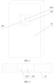
FIG. 2 is a structural diagram of a device body in an electronic device according to an embodiment of the present application; -
FIG. 3 is a schematic cross-sectional structural diagram 1 of a device body in an electronic device according to an embodiment of the present application; -
FIG. 4 is a schematic cross-sectional structural diagram 2 of a device body in an electronic device according to an embodiment of the present application; and -
FIG. 5 is a schematic cross-sectional structural diagram 3 of a device body in an electronic device according to an embodiment of the present application. - The following clearly and completely describes the technical solutions in the embodiments of the present application with reference to the accompanying drawings in the embodiments of the present application. Apparently, the described embodiments are some but not all of the embodiments of the present application. All other embodiments obtained by a person of ordinary skill in the art based on the embodiments of the present application without creative efforts shall fall within the protection scope of the present application.
- Unless otherwise defined, the technical terms or scientific terms used in the present application shall have the general meanings understood by a person of ordinary skill in the field of the present application. The "first", "second" and similar words used in the present application are only intended to distinguish different components, rather than to indicate any order, quantity or importance. Similarly, similar words such as "one piece" or "one" indicates the presence of at least one, rather than indicating a quantity limit. Similar words such as "connect" or "connection" are not limited to physical or mechanical connections, but may include electrical connections, no matter it is direct or indirect. "Upper", "lower", "left", "right", and the like are only intended to indicate a relative positional relationship. When absolute positions of the described object change, the relative positional relationship changes accordingly as well.
- As shown in
FIG. 1 to FIG. 5 , the embodiments of the present application provide an electronic device, including: - a
device body 10, where a sound-emitting device is installed in the device body, afirst sound cavity 102 is provided on thedevice body 10, and thefirst sound cavity 102 has an opening that communicates with the outside; and - a
camera apparatus 20, where thecamera apparatus 20 is detachably installed in thefirst sound cavity 102; - where in a case that the
camera apparatus 20 is installed in thefirst sound cavity 102, the sound cavity of the sound-emitting device has a first volume value, in a case that the camera apparatus is separated from the device body, the sound cavity of the sound-emitting device extends toward the first sound cavity and has a second volume value, and the first volume value is smaller than the second volume value. - In the embodiments of the present application, the
first sound cavity 102 may be a groove structure formed when one side of thedevice body 10 is sunken inwards, an opening is formed on thedevice body 10, and thecamera apparatus 20 can be inserted into thefirst sound cavity 102 through the opening and is installed fixedly in thefirst sound cavity 102 to fasten thecamera apparatus 20 on thedevice body 10. At the same time, thecamera apparatus 20 can also be disassembled from thefirst sound cavity 102 through the opening, to separate thecamera apparatus 20 from thedevice body 10. - Optionally, the fastening method of the
camera apparatus 20 and thedevice body 10 can be set according to actual needs, for example, the fastening can be achieved by means of snapping, or the fastening can be achieved by means of screws, which is not limited herein, as long as the detachable connection between thecamera apparatus 20 and thedevice body 10 can be realized. - When a larger sound cavity is required, the
camera apparatus 20 can be separated from thedevice body 10, so that the sound cavity of the sound-emitting device extends toward the first sound cavity and has a second volume value. When thecamera apparatus 20 needs to be installed on thedevice body 10 for use, such as charging or data transmission, thecamera apparatus 20 can be installed in thefirst sound cavity 102, and the sound cavity of the sound-emitting device is reduced to the first volume. - In the embodiments of the present application, the
camera apparatus 20 is detachably installed in thefirst sound cavity 102, so that when thecamera apparatus 20 needs to be installed and used, thecamera apparatus 20 is installed in thefirst sound cavity 102, and when a larger sound cavity needs to be used, thecamera apparatus 20 can be separated from thedevice body 10. In this way, sound cavity reuse is realized, so that the volume of the electronic device can be reduced, which is beneficial to miniaturized design of the electronic device. - It should be understood that, for the camera apparatus, by sharing space, the volume of the camera apparatus can be appropriately increased, thereby improving the resolution and zoom factor of the camera apparatus. For the sound-emitting device, by sharing space, the sound cavity can be appropriately increased, so that an ultra-low frequency and high-fidelity electro-acoustic system can be realized for the sound-emitting device.
- Optionally, in an embodiment, the sound-emitting device has a
second sound cavity 1011, thesecond sound cavity 1011 communicates with thefirst sound cavity 102, and thedevice body 10 further includes abaffle 103 adapted to the opening. - In a case that the
camera apparatus 20 is separated from thedevice body 10, thebaffle 103 covers the opening, and the sound cavity of the sound-emitting device is formed by the combination of thefirst sound cavity 102 and thesecond sound cavity 1011. - In this embodiment, when the
camera apparatus 20 is located in thefirst sound cavity 102, thecamera apparatus 20 seals the second sound cavity, and the second sound cavity forms the sound cavity of the sound-emitting device. - Optionally, in an embodiment, the
baffle 103 is slidably connected with thedevice body 10 to move between a first position and a second position, in a case that the baffle is in the first position, the baffle opens the opening, and in a case that the baffle is in the second position, thebaffle 103 covers the opening. - When the
baffle 103 is in the first position, thecamera apparatus 20 can be installed on thedevice body 10, or thecamera apparatus 20 can be separated from thedevice body 10. Specifically, the movement of thebaffle 103 can be manually controlled, or the movement of thebaffle 103 can be driven through setting. - For example, in an embodiment, a drive assembly and a control chip are further provided in the
device body 10, the drive assembly is connected with thebaffle 103, and the control chip is connected with the drive assembly and is configured to control the drive assembly to drive thebaffle 103 to move between the first position and the second position. - Optionally, in an embodiment, the drive assembly includes a motor and a drive circuit adapted to the motor. The rotating shaft of the motor can be connected with the
baffle 103. Specifically, the control chip can output a corresponding control instruction to the drive circuit when an operation command is received from the user, thereby controlling the movement of thebaffle 103. The movement of thebaffle 103 may be rotational movement or linear movement, which is not further limited herein. For example, in an embodiment, physical or virtual buttons may be provided for the user to input the operation instruction. - Of course, in other embodiments, the movement of the
baffle 103 may also be controlled manually. Thebaffle 103 may use a push-pull design, as shown inFIG. 2 . In this case, to facilitate the user to exert force to control the movement of thebaffle 103, in an embodiment, thebaffle 103 is provided with ahandle portion 1031, and at least a part of thehandle portion 1031 protrudes from thedevice body 10. - Optionally, in other embodiments, a block can also be designed to be detachably connected with the
device body 10, and when the block is installed on thedevice body 10, the block can cover the opening, so that thefirst sound cavity 102 and thesecond sound cavity 1011 are combined to form the sound cavity of the sound-emitting device. - In this embodiment, the
device body 10 may be provided with a notch adapted to thehandle portion 103 at the opening, and when thebaffle 103 is in the first position, thehandle portion 103 is located in the notch. Since the notch is provided to accommodate thehandle portion 103, thebaffle 103 can be prevented from occupying the opening, so that the size of the opening can be reduced. - Further, in an embodiment, the sound cavity of the sound-emitting device is a
second sound cavity 1011, thesecond sound cavity 1011 is made of a deformable material, in a case that thecamera apparatus 20 is installed in thefirst sound cavity 102, thesecond sound cavity 1011 is squeezed by thecamera apparatus 20 to have the first volume value, and in a case that thecamera apparatus 20 is separated from thedevice body 10, thesecond sound cavity 1011 extends towards thefirst sound cavity 102 and changes from the first volume value to the second volume value. - In this embodiment, the
second sound cavity 1011 is a sealed hollow cavity, and the size of thesecond sound cavity 1011 can be elastically changed. As shown inFIG. 4 , when thecamera apparatus 20 is separated from thedevice body 10, a part of thesecond sound cavity 1011 is located in thefirst sound cavity 102. As shown inFIG. 5 , when thecamera apparatus 20 is located in thefirst sound cavity 102, thecamera apparatus 20 squeezes thefirst sound cavity 102, so that the volume of thefirst sound cavity 102 is reduced. In this case, a part of thesecond sound cavity 1011 can be located in thefirst sound cavity 102, or the entiresecond sound cavity 1011 may not be located in thefirst sound cavity 102. - It should be noted that, the positional relationship between the
first sound cavity 102 and thesecond sound cavity 1011 can be set according to actual needs, which is not further limited here. - Optionally, the opening may be provided on the back of the device body. Specifically, the device body is provided with a display screen, and the back specifically refers to a side of the device body away from the display screen.
- Further, in a case that the
camera apparatus 20 is installed in thefirst sound cavity 102, thedevice body 10 controls thecamera apparatus 20 to work, and in a case that thecamera apparatus 20 is separated from the device body, thecamera apparatus 20 works independent of thedevice body 10, or thedevice body 10 controls thecamera apparatus 20 to work. Therefore, thecamera apparatus 20 can optionally work independent of thedevice body 10 or work under the control of thedevice body 10, which is more flexible and convenient to use. - It should be noted that the sound-emitting device may include a coil diaphragm and a magnet, where the coil diaphragm vibrates under the action of the magnetic force of the magnet to generate sound. The size of the sound cavity of the sound-emitting device affects the sound-emitting effect of the sound-emitting component. For example, as the volume of the rear sound cavity constantly increases, the low-frequency peak of the frequency response curve of the sound constantly moves toward the low frequency, so that the low-frequency characteristics can be improved.
- In the embodiments of the present application, the installation space of the
camera apparatus 20 and the sound cavity of the sound-emitting device share space, thereby improving the space utilization of the electronic device, and providing a solution to the problem of insufficient internal space of the electronic device. Due to space sharing, a camera with a higher resolution and a higher zoom factor can be used, so that the resolution and the zoom factor of the electronic device are not limited, to improve the performance of thecamera apparatus 20. Further, through space sharing, the space of the sound cavity of the sound-emitting device is increased, so that an ultra-low frequency and high-fidelity electro-acoustic system can be realized. - The foregoing descriptions are merely specific implementations of the present application, but are not intended to limit the protection scope of the present application. Any variation or replacement readily figured out by a person skilled in the art within the technical scope disclosed in the present application shall fall within the protection scope of the present application. Therefore, the protection scope of the present application shall be subject to the protection scope of the claims.
Claims (9)
- An electronic device, comprising:a device body, wherein a sound-emitting device is installed in the device body, a first sound cavity is provided on the device body, and the first sound cavity has an opening that communicates with the outside; anda camera apparatus, wherein the camera apparatus is detachably installed in the first sound cavity;wherein in a case that the camera apparatus is installed in the first sound cavity, the sound cavity of the sound-emitting device has a first volume value, in a case that the camera apparatus is separated from the device body, the sound cavity of the sound-emitting device extends toward the first sound cavity and has a second volume value, and the first volume value is smaller than the second volume value.
- The electronic device according to claim 1, wherein the sound-emitting device has a second sound cavity, the second sound cavity communicates with the first sound cavity, and the device body further comprises a baffle adapted to the opening;
wherein in a case that the camera apparatus is separated from the device body, the baffle covers the opening, and the sound cavity of the sound-emitting device is formed by the combination of the first sound cavity and the second sound cavity. - The electronic device according to claim 2, wherein the baffle is slidably connected with the device body to move between a first position and a second position, in a case that the baffle is in the first position, the baffle opens the opening, and in a case that the baffle is in the second position, the baffle covers the opening.
- The electronic device according to claim 3, wherein a drive assembly and a control chip are further provided in the device body, the drive assembly is connected with the baffle, and the control chip is connected with the drive assembly and is configured to control the drive assembly to drive the baffle to move between the first position and the second position.
- The electronic device according to claim 4, wherein the drive assembly comprises a motor and a drive circuit adapted to the motor.
- The electronic device according to claim 3, wherein the baffle is provided with a handle portion, and at least a part of the handle portion protrudes from the device body.
- The electronic device according to claim 1, wherein the sound cavity of the sound-emitting device is a second sound cavity, the second sound cavity is made of a deformable material, in a case that the camera apparatus is installed in the first sound cavity, the second sound cavity is squeezed by the camera apparatus to have the first volume value, and in a case that the camera apparatus is separated from the device body, the second sound cavity extends towards the first sound cavity and changes from the first volume value to the second volume value.
- The electronic device according to claim 1, wherein the opening is provided on the back of the device body.
- The electronic device according to any one of claims 1 to 8, wherein in a case that the camera apparatus is installed in the first sound cavity, the device body controls the camera apparatus to work, and in a case that the camera apparatus is separated from the device body, the camera apparatus works independent of the device body, or the device body controls the camera apparatus to work.
Applications Claiming Priority (2)
| Application Number | Priority Date | Filing Date | Title |
|---|---|---|---|
| CN202010338949.8A CN111526453B (en) | 2020-04-26 | 2020-04-26 | Electronic device |
| PCT/CN2021/089223 WO2021218796A1 (en) | 2020-04-26 | 2021-04-23 | Electronic device |
Publications (2)
| Publication Number | Publication Date |
|---|---|
| EP4145852A1 true EP4145852A1 (en) | 2023-03-08 |
| EP4145852A4 EP4145852A4 (en) | 2023-11-01 |
Family
ID=71903540
Family Applications (1)
| Application Number | Title | Priority Date | Filing Date |
|---|---|---|---|
| EP21797140.7A Pending EP4145852A4 (en) | 2020-04-26 | 2021-04-23 | ELECTRONIC DEVICE |
Country Status (5)
| Country | Link |
|---|---|
| US (1) | US12095937B2 (en) |
| EP (1) | EP4145852A4 (en) |
| JP (1) | JP7459294B2 (en) |
| CN (1) | CN111526453B (en) |
| WO (1) | WO2021218796A1 (en) |
Families Citing this family (5)
| Publication number | Priority date | Publication date | Assignee | Title |
|---|---|---|---|---|
| CN111526453B (en) | 2020-04-26 | 2022-01-07 | 维沃移动通信有限公司 | Electronic device |
| CN112073858B (en) * | 2020-09-09 | 2022-08-26 | 维沃移动通信有限公司 | Audio output device, electronic apparatus, control method, and control device |
| CN112600963B (en) * | 2020-12-11 | 2023-03-21 | 维沃移动通信有限公司 | Electronic equipment |
| CN113099014B (en) * | 2021-04-26 | 2023-03-21 | 维沃移动通信有限公司 | Electronic device |
| CN115623330B (en) * | 2022-10-10 | 2025-02-07 | 维沃移动通信有限公司 | Electronic device and control method |
Family Cites Families (12)
| Publication number | Priority date | Publication date | Assignee | Title |
|---|---|---|---|---|
| JP2002152357A (en) * | 2000-11-07 | 2002-05-24 | Kyocera Corp | Mobile communication terminal, mobile camera, and mobile communication terminal with mobile camera |
| JP2002374447A (en) * | 2001-04-12 | 2002-12-26 | Fuji Photo Film Co Ltd | Cradle for information equipment, cradle for digital camera and camera system |
| US6980828B2 (en) * | 2002-12-03 | 2005-12-27 | Nokia Corporation | Multi-media mobile communication device and related construction method |
| US20090169040A1 (en) * | 2007-12-27 | 2009-07-02 | Motorola Inc | Devices and methods for enhancing the frequency output of a portable audio device |
| CN203219475U (en) * | 2013-05-03 | 2013-09-25 | 广东欧珀移动通信有限公司 | Loudspeaker structures and mobile devices with expandable sound chambers |
| CN103596102A (en) * | 2013-09-24 | 2014-02-19 | 小米科技有限责任公司 | Device for regulating tone quality and terminal equipment |
| CN205921740U (en) * | 2016-07-15 | 2017-02-01 | 珠海市魅族科技有限公司 | Mobile terminal and sound cavity structure thereof |
| CN208353378U (en) * | 2018-05-31 | 2019-01-08 | 上海爱优威软件开发有限公司 | The terminal for having detachable abnormity screen |
| CN109324780B (en) * | 2018-09-27 | 2021-01-15 | 联想(北京)有限公司 | Method for improving sound output effect and electronic equipment |
| US11476883B2 (en) * | 2019-02-14 | 2022-10-18 | Apple Inc. | Electronic devices having optical and audio components |
| CN111526453B (en) * | 2020-04-26 | 2022-01-07 | 维沃移动通信有限公司 | Electronic device |
| CN112600963B (en) * | 2020-12-11 | 2023-03-21 | 维沃移动通信有限公司 | Electronic equipment |
-
2020
- 2020-04-26 CN CN202010338949.8A patent/CN111526453B/en active Active
-
2021
- 2021-04-23 WO PCT/CN2021/089223 patent/WO2021218796A1/en not_active Ceased
- 2021-04-23 JP JP2022562450A patent/JP7459294B2/en active Active
- 2021-04-23 EP EP21797140.7A patent/EP4145852A4/en active Pending
-
2022
- 2022-10-21 US US17/971,144 patent/US12095937B2/en active Active
Also Published As
| Publication number | Publication date |
|---|---|
| WO2021218796A1 (en) | 2021-11-04 |
| US12095937B2 (en) | 2024-09-17 |
| CN111526453B (en) | 2022-01-07 |
| US20230041843A1 (en) | 2023-02-09 |
| JP2023522633A (en) | 2023-05-31 |
| CN111526453A (en) | 2020-08-11 |
| EP4145852A4 (en) | 2023-11-01 |
| JP7459294B2 (en) | 2024-04-01 |
Similar Documents
| Publication | Publication Date | Title |
|---|---|---|
| US12095937B2 (en) | Electronic device | |
| US11108902B2 (en) | Camera assembly and terminal | |
| CN112073858B (en) | Audio output device, electronic apparatus, control method, and control device | |
| EP4184284A1 (en) | Electronic device including camera module and operation method of same electronic device | |
| CN111083259A (en) | Electronic device, control method thereof, control device thereof, and computer-readable storage medium | |
| EP3809679B1 (en) | Receiver module and terminal device | |
| CN209488641U (en) | Camera modules and electronics | |
| CN108769328B (en) | Combined device of receiver and camera and mobile terminal | |
| WO2019096125A1 (en) | Housing assembly, functional assembly and mobile terminal | |
| CN108322581A (en) | Electronic component and electronic equipment | |
| CN209283475U (en) | A kind of electronic equipment | |
| CN111327986B (en) | Electronic equipment and earphone | |
| CN113873407B (en) | Speaker control method, speaker module and electronic device | |
| WO2019228206A1 (en) | Circuit control method and mobile terminal | |
| CN210469392U (en) | Electronic device | |
| CN208596282U (en) | Intelligent watch with toggle switching function | |
| CN221748590U (en) | Speaker unit | |
| CN212324196U (en) | Electronic equipment | |
| CN218446948U (en) | Remote controller and communication system | |
| CN221748586U (en) | Speaker unit | |
| CN221748588U (en) | A speaker unit | |
| CN222089755U (en) | Miniature loudspeaker | |
| CN218788132U (en) | Internet of things monitoring system | |
| CN210899446U (en) | Linkage system of projector | |
| CN216600059U (en) | Flat panel loudspeaker based on flat panel spring |
Legal Events
| Date | Code | Title | Description |
|---|---|---|---|
| STAA | Information on the status of an ep patent application or granted ep patent |
Free format text: STATUS: THE INTERNATIONAL PUBLICATION HAS BEEN MADE |
|
| PUAI | Public reference made under article 153(3) epc to a published international application that has entered the european phase |
Free format text: ORIGINAL CODE: 0009012 |
|
| STAA | Information on the status of an ep patent application or granted ep patent |
Free format text: STATUS: REQUEST FOR EXAMINATION WAS MADE |
|
| 17P | Request for examination filed |
Effective date: 20221115 |
|
| AK | Designated contracting states |
Kind code of ref document: A1 Designated state(s): AL AT BE BG CH CY CZ DE DK EE ES FI FR GB GR HR HU IE IS IT LI LT LU LV MC MK MT NL NO PL PT RO RS SE SI SK SM TR |
|
| DAV | Request for validation of the european patent (deleted) | ||
| DAX | Request for extension of the european patent (deleted) | ||
| REG | Reference to a national code |
Ref country code: DE Ref legal event code: R079 Free format text: PREVIOUS MAIN CLASS: H04R0001220000 Ipc: H04R0001280000 |
|
| A4 | Supplementary search report drawn up and despatched |
Effective date: 20230929 |
|
| RIC1 | Information provided on ipc code assigned before grant |
Ipc: H04N 23/57 20230101ALN20230925BHEP Ipc: H04N 23/50 20230101ALN20230925BHEP Ipc: H04M 1/03 20060101ALN20230925BHEP Ipc: H04R 1/02 20060101ALN20230925BHEP Ipc: H04M 1/02 20060101ALI20230925BHEP Ipc: H04R 1/28 20060101AFI20230925BHEP |
|
| STAA | Information on the status of an ep patent application or granted ep patent |
Free format text: STATUS: EXAMINATION IS IN PROGRESS |
|
| 17Q | First examination report despatched |
Effective date: 20250606 |