EP4145604A1 - Battery pack and vehicle - Google Patents
Battery pack and vehicle Download PDFInfo
- Publication number
- EP4145604A1 EP4145604A1 EP21823055.5A EP21823055A EP4145604A1 EP 4145604 A1 EP4145604 A1 EP 4145604A1 EP 21823055 A EP21823055 A EP 21823055A EP 4145604 A1 EP4145604 A1 EP 4145604A1
- Authority
- EP
- European Patent Office
- Prior art keywords
- edge
- battery pack
- vapor chamber
- receiving space
- tray
- Prior art date
- Legal status (The legal status is an assumption and is not a legal conclusion. Google has not performed a legal analysis and makes no representation as to the accuracy of the status listed.)
- Granted
Links
Images


Classifications
-
- H—ELECTRICITY
- H01—ELECTRIC ELEMENTS
- H01M—PROCESSES OR MEANS, e.g. BATTERIES, FOR THE DIRECT CONVERSION OF CHEMICAL ENERGY INTO ELECTRICAL ENERGY
- H01M10/00—Secondary cells; Manufacture thereof
- H01M10/60—Heating or cooling; Temperature control
- H01M10/61—Types of temperature control
- H01M10/617—Types of temperature control for achieving uniformity or desired distribution of temperature
-
- H—ELECTRICITY
- H01—ELECTRIC ELEMENTS
- H01M—PROCESSES OR MEANS, e.g. BATTERIES, FOR THE DIRECT CONVERSION OF CHEMICAL ENERGY INTO ELECTRICAL ENERGY
- H01M10/00—Secondary cells; Manufacture thereof
- H01M10/60—Heating or cooling; Temperature control
- H01M10/61—Types of temperature control
- H01M10/615—Heating or keeping warm
-
- H—ELECTRICITY
- H01—ELECTRIC ELEMENTS
- H01M—PROCESSES OR MEANS, e.g. BATTERIES, FOR THE DIRECT CONVERSION OF CHEMICAL ENERGY INTO ELECTRICAL ENERGY
- H01M10/00—Secondary cells; Manufacture thereof
- H01M10/60—Heating or cooling; Temperature control
- H01M10/61—Types of temperature control
- H01M10/613—Cooling or keeping cold
-
- H—ELECTRICITY
- H01—ELECTRIC ELEMENTS
- H01M—PROCESSES OR MEANS, e.g. BATTERIES, FOR THE DIRECT CONVERSION OF CHEMICAL ENERGY INTO ELECTRICAL ENERGY
- H01M10/00—Secondary cells; Manufacture thereof
- H01M10/60—Heating or cooling; Temperature control
- H01M10/62—Heating or cooling; Temperature control specially adapted for specific applications
- H01M10/625—Vehicles
-
- H—ELECTRICITY
- H01—ELECTRIC ELEMENTS
- H01M—PROCESSES OR MEANS, e.g. BATTERIES, FOR THE DIRECT CONVERSION OF CHEMICAL ENERGY INTO ELECTRICAL ENERGY
- H01M10/00—Secondary cells; Manufacture thereof
- H01M10/60—Heating or cooling; Temperature control
- H01M10/64—Heating or cooling; Temperature control characterised by the shape of the cells
- H01M10/647—Prismatic or flat cells, e.g. pouch cells
-
- H—ELECTRICITY
- H01—ELECTRIC ELEMENTS
- H01M—PROCESSES OR MEANS, e.g. BATTERIES, FOR THE DIRECT CONVERSION OF CHEMICAL ENERGY INTO ELECTRICAL ENERGY
- H01M10/00—Secondary cells; Manufacture thereof
- H01M10/60—Heating or cooling; Temperature control
- H01M10/65—Means for temperature control structurally associated with the cells
- H01M10/655—Solid structures for heat exchange or heat conduction
- H01M10/6552—Closed pipes transferring heat by thermal conductivity or phase transition, e.g. heat pipes
-
- H—ELECTRICITY
- H01—ELECTRIC ELEMENTS
- H01M—PROCESSES OR MEANS, e.g. BATTERIES, FOR THE DIRECT CONVERSION OF CHEMICAL ENERGY INTO ELECTRICAL ENERGY
- H01M10/00—Secondary cells; Manufacture thereof
- H01M10/60—Heating or cooling; Temperature control
- H01M10/65—Means for temperature control structurally associated with the cells
- H01M10/655—Solid structures for heat exchange or heat conduction
- H01M10/6554—Rods or plates
-
- H—ELECTRICITY
- H01—ELECTRIC ELEMENTS
- H01M—PROCESSES OR MEANS, e.g. BATTERIES, FOR THE DIRECT CONVERSION OF CHEMICAL ENERGY INTO ELECTRICAL ENERGY
- H01M10/00—Secondary cells; Manufacture thereof
- H01M10/60—Heating or cooling; Temperature control
- H01M10/65—Means for temperature control structurally associated with the cells
- H01M10/655—Solid structures for heat exchange or heat conduction
- H01M10/6556—Solid parts with flow channel passages or pipes for heat exchange
-
- H—ELECTRICITY
- H01—ELECTRIC ELEMENTS
- H01M—PROCESSES OR MEANS, e.g. BATTERIES, FOR THE DIRECT CONVERSION OF CHEMICAL ENERGY INTO ELECTRICAL ENERGY
- H01M10/00—Secondary cells; Manufacture thereof
- H01M10/60—Heating or cooling; Temperature control
- H01M10/65—Means for temperature control structurally associated with the cells
- H01M10/656—Means for temperature control structurally associated with the cells characterised by the type of heat-exchange fluid
- H01M10/6567—Liquids
- H01M10/6568—Liquids characterised by flow circuits, e.g. loops, located externally to the cells or cell casings
-
- H—ELECTRICITY
- H01—ELECTRIC ELEMENTS
- H01M—PROCESSES OR MEANS, e.g. BATTERIES, FOR THE DIRECT CONVERSION OF CHEMICAL ENERGY INTO ELECTRICAL ENERGY
- H01M50/00—Constructional details or processes of manufacture of the non-active parts of electrochemical cells other than fuel cells, e.g. hybrid cells
- H01M50/20—Mountings; Secondary casings or frames; Racks, modules or packs; Suspension devices; Shock absorbers; Transport or carrying devices; Holders
- H01M50/204—Racks, modules or packs for multiple batteries or multiple cells
-
- H—ELECTRICITY
- H01—ELECTRIC ELEMENTS
- H01M—PROCESSES OR MEANS, e.g. BATTERIES, FOR THE DIRECT CONVERSION OF CHEMICAL ENERGY INTO ELECTRICAL ENERGY
- H01M50/00—Constructional details or processes of manufacture of the non-active parts of electrochemical cells other than fuel cells, e.g. hybrid cells
- H01M50/20—Mountings; Secondary casings or frames; Racks, modules or packs; Suspension devices; Shock absorbers; Transport or carrying devices; Holders
- H01M50/204—Racks, modules or packs for multiple batteries or multiple cells
- H01M50/207—Racks, modules or packs for multiple batteries or multiple cells characterised by their shape
- H01M50/209—Racks, modules or packs for multiple batteries or multiple cells characterised by their shape adapted for prismatic or rectangular cells
-
- H—ELECTRICITY
- H01—ELECTRIC ELEMENTS
- H01M—PROCESSES OR MEANS, e.g. BATTERIES, FOR THE DIRECT CONVERSION OF CHEMICAL ENERGY INTO ELECTRICAL ENERGY
- H01M50/00—Constructional details or processes of manufacture of the non-active parts of electrochemical cells other than fuel cells, e.g. hybrid cells
- H01M50/20—Mountings; Secondary casings or frames; Racks, modules or packs; Suspension devices; Shock absorbers; Transport or carrying devices; Holders
- H01M50/218—Mountings; Secondary casings or frames; Racks, modules or packs; Suspension devices; Shock absorbers; Transport or carrying devices; Holders characterised by the material
- H01M50/22—Mountings; Secondary casings or frames; Racks, modules or packs; Suspension devices; Shock absorbers; Transport or carrying devices; Holders characterised by the material of the casings or racks
- H01M50/222—Inorganic material
- H01M50/224—Metals
-
- H—ELECTRICITY
- H01—ELECTRIC ELEMENTS
- H01M—PROCESSES OR MEANS, e.g. BATTERIES, FOR THE DIRECT CONVERSION OF CHEMICAL ENERGY INTO ELECTRICAL ENERGY
- H01M50/00—Constructional details or processes of manufacture of the non-active parts of electrochemical cells other than fuel cells, e.g. hybrid cells
- H01M50/20—Mountings; Secondary casings or frames; Racks, modules or packs; Suspension devices; Shock absorbers; Transport or carrying devices; Holders
- H01M50/233—Mountings; Secondary casings or frames; Racks, modules or packs; Suspension devices; Shock absorbers; Transport or carrying devices; Holders characterised by physical properties of casings or racks, e.g. dimensions
- H01M50/24—Mountings; Secondary casings or frames; Racks, modules or packs; Suspension devices; Shock absorbers; Transport or carrying devices; Holders characterised by physical properties of casings or racks, e.g. dimensions adapted for protecting batteries from their environment, e.g. from corrosion
-
- H—ELECTRICITY
- H01—ELECTRIC ELEMENTS
- H01M—PROCESSES OR MEANS, e.g. BATTERIES, FOR THE DIRECT CONVERSION OF CHEMICAL ENERGY INTO ELECTRICAL ENERGY
- H01M50/00—Constructional details or processes of manufacture of the non-active parts of electrochemical cells other than fuel cells, e.g. hybrid cells
- H01M50/20—Mountings; Secondary casings or frames; Racks, modules or packs; Suspension devices; Shock absorbers; Transport or carrying devices; Holders
- H01M50/233—Mountings; Secondary casings or frames; Racks, modules or packs; Suspension devices; Shock absorbers; Transport or carrying devices; Holders characterised by physical properties of casings or racks, e.g. dimensions
- H01M50/242—Mountings; Secondary casings or frames; Racks, modules or packs; Suspension devices; Shock absorbers; Transport or carrying devices; Holders characterised by physical properties of casings or racks, e.g. dimensions adapted for protecting batteries against vibrations, collision impact or swelling
-
- H—ELECTRICITY
- H01—ELECTRIC ELEMENTS
- H01M—PROCESSES OR MEANS, e.g. BATTERIES, FOR THE DIRECT CONVERSION OF CHEMICAL ENERGY INTO ELECTRICAL ENERGY
- H01M50/00—Constructional details or processes of manufacture of the non-active parts of electrochemical cells other than fuel cells, e.g. hybrid cells
- H01M50/20—Mountings; Secondary casings or frames; Racks, modules or packs; Suspension devices; Shock absorbers; Transport or carrying devices; Holders
- H01M50/244—Secondary casings; Racks; Suspension devices; Carrying devices; Holders characterised by their mounting method
-
- H—ELECTRICITY
- H01—ELECTRIC ELEMENTS
- H01M—PROCESSES OR MEANS, e.g. BATTERIES, FOR THE DIRECT CONVERSION OF CHEMICAL ENERGY INTO ELECTRICAL ENERGY
- H01M50/00—Constructional details or processes of manufacture of the non-active parts of electrochemical cells other than fuel cells, e.g. hybrid cells
- H01M50/20—Mountings; Secondary casings or frames; Racks, modules or packs; Suspension devices; Shock absorbers; Transport or carrying devices; Holders
- H01M50/249—Mountings; Secondary casings or frames; Racks, modules or packs; Suspension devices; Shock absorbers; Transport or carrying devices; Holders specially adapted for aircraft or vehicles, e.g. cars or trains
-
- H—ELECTRICITY
- H01—ELECTRIC ELEMENTS
- H01M—PROCESSES OR MEANS, e.g. BATTERIES, FOR THE DIRECT CONVERSION OF CHEMICAL ENERGY INTO ELECTRICAL ENERGY
- H01M50/00—Constructional details or processes of manufacture of the non-active parts of electrochemical cells other than fuel cells, e.g. hybrid cells
- H01M50/20—Mountings; Secondary casings or frames; Racks, modules or packs; Suspension devices; Shock absorbers; Transport or carrying devices; Holders
- H01M50/262—Mountings; Secondary casings or frames; Racks, modules or packs; Suspension devices; Shock absorbers; Transport or carrying devices; Holders with fastening means, e.g. locks
- H01M50/264—Mountings; Secondary casings or frames; Racks, modules or packs; Suspension devices; Shock absorbers; Transport or carrying devices; Holders with fastening means, e.g. locks for cells or batteries, e.g. straps, tie rods or peripheral frames
-
- H—ELECTRICITY
- H01—ELECTRIC ELEMENTS
- H01M—PROCESSES OR MEANS, e.g. BATTERIES, FOR THE DIRECT CONVERSION OF CHEMICAL ENERGY INTO ELECTRICAL ENERGY
- H01M50/00—Constructional details or processes of manufacture of the non-active parts of electrochemical cells other than fuel cells, e.g. hybrid cells
- H01M50/20—Mountings; Secondary casings or frames; Racks, modules or packs; Suspension devices; Shock absorbers; Transport or carrying devices; Holders
- H01M50/271—Lids or covers for the racks or secondary casings
-
- H—ELECTRICITY
- H01—ELECTRIC ELEMENTS
- H01M—PROCESSES OR MEANS, e.g. BATTERIES, FOR THE DIRECT CONVERSION OF CHEMICAL ENERGY INTO ELECTRICAL ENERGY
- H01M2220/00—Batteries for particular applications
- H01M2220/20—Batteries in motive systems, e.g. vehicle, ship, plane
-
- Y—GENERAL TAGGING OF NEW TECHNOLOGICAL DEVELOPMENTS; GENERAL TAGGING OF CROSS-SECTIONAL TECHNOLOGIES SPANNING OVER SEVERAL SECTIONS OF THE IPC; TECHNICAL SUBJECTS COVERED BY FORMER USPC CROSS-REFERENCE ART COLLECTIONS [XRACs] AND DIGESTS
- Y02—TECHNOLOGIES OR APPLICATIONS FOR MITIGATION OR ADAPTATION AGAINST CLIMATE CHANGE
- Y02E—REDUCTION OF GREENHOUSE GAS [GHG] EMISSIONS, RELATED TO ENERGY GENERATION, TRANSMISSION OR DISTRIBUTION
- Y02E60/00—Enabling technologies; Technologies with a potential or indirect contribution to GHG emissions mitigation
- Y02E60/10—Energy storage using batteries
Definitions
- the present disclosure relates to the field of batteries, and more particularly to a battery pack and vehicle.
- a tray is generally used to load a power battery and is sealed by a tray cover to form a battery pack, and the battery pack is mounted on an electric vehicle.
- an edge beam of a tray is designed to be light in weight and cost reductive, but there is a problem of strength of the tray.
- the edge beam of the tray is easily extruded to be deformed, so that a battery pole in the tray is extruded, and safety accidents such as battery short circuit are caused.
- the present disclosure is to resolve at least one of the technical problems in the related art.
- the present disclosure provides a battery pack to prevent the battery pack from being extruded to be deformed.
- the present disclosure also provides a vehicle having the above battery pack.
- a battery pack for powering a vehicle includes a tray and a vapor chamber; the tray includes first edge beams for enclosing a receiving space having a top opening; the vapor chamber is provided at the top opening of the tray and includes two opposite first edge portions, and both of the first edge portions are mounted on the first edge beams; and a clamping slot is provided on an inner surface of one of the first edge beam and the first edge portion facing the receiving space, and the other of the first edge beam and the first edge portion is inserted into the clamping slot.
- the vapor chamber supports the first edge beams, and when the tray is extruded or collided, the tray can transmit a force to the vapor chamber, thereby increasing the structural strength of the tray and preventing the first edge beams from deforming to extrude the battery module in the receiving space after being extruded to achieve the purpose of protecting the battery module in the receiving space, so that the operation of the battery module is safe and reliable.
- the tray has two first edge beams spaced apart, and the two first edge beams respectively cooperate with two first edge portions.
- the clamping slot is provided on an inner surface of the first edge beam facing the receiving space, and the first edge portion is inserted into the clamping slot of the first edge beam.
- the first edge portion contacts with or abuts against a bottom wall of the clamping slot, and the first edge portion is adhered to a side wall of the clamping slot.
- the battery pack further includes a number of cooling tubes provided in sequence on an outer surface of the vapor chamber facing away from the receiving space, and a heater provided between every two adjacent cooling tubes.
- the cooling tubes are integrally aluminum-extruded with the vapor chamber, and the heaters are heating films.
- a thickness of the cooling tubes is greater than a thickness of the heating film.
- the tray further includes two second edge beams provided opposite to each other and a reinforcing beam, the first edge beams and the two second edge beams together enclose the receiving space, and the reinforcing beam is parallel with the second edge beams.
- the vapor chamber includes a connecting region and a bearing region other than the connecting region, a thickness of the connecting region is greater than a thickness of the bearing region, and the connecting region is connected to the reinforcing beam.
- the connecting region of the vapor chamber is riveted or screwed to the reinforcing beam.
- a parallel direction of the reinforcing beam and the second edge beam is a lengthwise extension direction of the reinforcing beam
- two bosses are provided on the inner surface of the vapor chamber facing the receiving space, and the two bosses respectively abut against two end faces of the reinforcing beam along the parallel direction.
- the vapor chamber is provided with a connecting member for connection to a vehicle.
- the battery pack further includes a battery module placed in the receiving space, and the vapor chamber is bonded to the battery module.
- the battery pack further includes a cover plate, where the cover plate is located on the vapor chamber and covers the top opening of the receiving space, and a sealing cushion is provided between the cover plate and the vapor chamber.
- the vehicle according to an embodiment of the present disclosure includes the battery pack according to the above embodiment of the present disclosure.
- the vehicle according to an embodiment of the present disclosure operates safely and reliably.
- orientations or position relationships indicated by terms such as “center”, “longitudinal”, “transverse”, “length”, “width”, “thickness”, “up”, “down”, “front”, “back”, “left”, “right”, “vertical”, “horizontal”, “top”, “bottom”, “inner”, “outer”, “clockwise”, “counterclockwise”, “axial”, “radial”, and “circumferential” are orientations or position relationship shown based on the accompanying drawings, and are merely used for describing the present disclosure and simplifying the description, rather than indicating or implying that the apparatus or element should have a particular orientation or be constructed and operated in a particular orientation, and therefore, should not be construed as a limitation on the present disclosure.
- a feature defined to be “first” or “second” may explicitly or implicitly include one or more features. In the description of the present disclosure, unless stated otherwise, the meaning of "a number of" is two or more than two.
- connection may be a fixed connection, a detachable connection, or an integral connection; or the connection may be a mechanical connection or an electrical connection; or the connection may be a direct connection, an indirect connection through an intermediary, or internal communication between two components.
- a battery pack 1000 that may be used to power a vehicle according to an embodiment of the present disclosure is described below with reference to FIGS. 1-10 .
- the battery pack 1000 includes a tray 2 and a vapor chamber 3, where the tray 2 includes first edge beams 21 for enclosing a receiving space 211 having a top opening, the vapor chamber 3 is provided at the top opening of the tray 2, the vapor chamber 3 includes two opposite first edge portions 32, and both of the two first edge portions 32 are mounted on the first edge beams 21; where one of the first edge beam 21 and the first edge portion 32 is provided with a clamping slot 212 on an inner surface facing the receiving space 211, and the other of the first edge beam 21 and the first edge portion 32 is inserted into the clamping slot 212.
- the other one of the first edge beam 21 and the first edge portion 32 is inserted into the clamping slot 212, so that both the first edge portions 32 of the vapor chamber 3 cooperate with the first edge beams 21 enclosing the receiving space 211, so that the vapor chamber 3 can support the first edge beams 21, and when the tray 2 is extruded or collided, the tray 2 can transmit a force to the vapor chamber 3, thereby increasing the structural strength of the tray 2 and preventing the first edge beams 21 from deforming after being extruded.
- the first edge beam 21 and the first edge portion 32 are fitted by snap-fitting a clamping slot 212, the reliability of the connection between the first edge beam 21 and the first edge portion 32 can be improved.
- the battery pack 1000 further includes a battery module 1 placed in the receiving space 211, and the vapor chamber 3 is located above the battery module 1.
- the battery module 1 can be provided in the receiving space 211, and by arranging the vapor chamber 3 at the top opening of the receiving space 211 and above the battery module 1, heat exchange can be performed between the vapor chamber 3 and the battery module 1 so as to heat and/or cool the battery module 1, thereby satisfying the cooling requirement of the battery module 1 during charging and discharging and/or satisfying the heating requirement of the battery module 1 in a low-temperature environment.
- the battery module 1 may be adhered to the vapor chamber 3, and more specifically, as shown in FIG. 1 , the vapor chamber 3 and the battery module 1 may be adhered by the thermally conductive structural adhesive 4, so that the heat exchange efficiency between the vapor chamber 3 and the battery module 1 may be improved.
- the present disclosure is not limited thereto, and for example, the battery module 1 and the vapor chamber 3 may not be connected to each other, or may be connected to each other by other means, which will not be described in detail herein.
- the vapor chamber 3 supports the first edge beams 21, and when the tray 2 is extruded or collided, the tray 2 can transmit a force to the vapor chamber 3, thereby increasing the structural strength of the tray 2 and preventing the first edge beams 21 from deforming after being extruded to achieve the purpose of protecting the battery module 1 in the receiving space 211, so that the operation of the battery module 1 is safe and reliable.
- the vapor chamber 3 is provided at the top opening of the tray 2 where the first edge beams 21 are easily deformed, the first edge beams 21 can be better prevented from being deformed to extrude the battery module 1.
- the tray 2 has two first edge beams 21 spaced apart that mate with two first edge portions 32, respectively. It can be appreciated that by respectively engaging the two first edge portions 32 of the vapor chamber 3 with the two first edge beams 21 of the tray 2, the vapor chamber 3 is supported between the two first edge beams 21 so as to prevent the receiving space 211 between the two first edge beams 21 from being deformed after being extruded, thereby serving the purpose of protecting the battery module 1 in the receiving space 211 to make the operation of the battery module 1 smooth and reliable.
- the clamping slot 212 is provided on an inner surface of the first edge beam 21 facing the receiving space 211, and the first edge portion 32 is inserted into the clamping slot 212 of the first edge beam 21.
- the stability of the vapor chamber 3 supporting the first edge beam 21 is thereby improved, and by machining the clamping slot 212 on the first edge beam 21, the machining of the vapor chamber 3 can be simplified, which better meets the practical production requirements.
- the first edge portion 32 contacts with or abuts against the bottom wall of the clamping slot 212, and the first edge portion 32 adheres to a side wall of the clamping slot 212, the stability and reliability of the vapor chamber 3 supporting the first edge beam 21 can thereby be improved, and thereby enabling the first edge portion 32 to be securely positioned within the clamping slot 212.
- the first edge portion 32 can be adhered to the side wall of the clamping slot 212 so as to further improve the connection strength between the vapor chamber 3 and the tray 2, thereby enabling the vapor chamber 3 to stably support the inside of the first edge beam 21.
- the tray 2 can transmit a force to the vapor chamber 3, thereby increasing the structural strength of the tray 2 and preventing the first edge beams 21 from deforming to extrude the battery module 1 after being extruded to protect the battery module 1 in the receiving space 211 to make the operation of the battery module 1 safe and reliable.
- the battery pack 1000 further includes a cover plate 22 located on the vapor chamber 3 and covers the top opening of the receiving space 211, and a sealing cushion 5 is provided between the cover plate 22 and the vapor chamber 3.
- the top opening of the receiving space 211 is sealed by the cover plate 22 to prevent external dust or liquid from entering the receiving space 211 to affect the operation of the battery module 1, thereby ensuring smooth and reliable operation of the battery module 1.
- a sealing cushion 5 is provided between the cover plate 22 and the vapor chamber 3, so that the top opening of the receiving space 211 can be better sealed by the sealing cushion 5, the sealing performance of the receiving space 211 can be improved, and the effects of vibration damping and noise reduction can be achieved.
- the cover plate 22 is connected to the tray 2 using bolts and extrudes the sealing cushion 5, and the receiving space 211 is sealed due to the resilient properties of the sealing cushion 5.
- the first edge portion 32 is located between the clamping slot 212 and the cover plate 22. Since both ends of the vapor chamber 3 are provided with the first edge portions 32, and the two first edge beams 21 of the tray 2 are provided with the clamping slots 212, the vapor chamber 3 can be stably supported between the two first edge beams 21 by extending the two first edge portions 32 of the vapor chamber 3 into the clamping slots 212 of the two first edge beams 21, thereby improving the structural strength of the tray 2.
- the vapor chamber 3 By covering the vapor chamber 3 with a cover plate 22 such that the first edge portion 32 of the vapor chamber 3 is provided between the clamping slot 212 and the cover plate 22, the vapor chamber 3 can be clamped by the cooperation of the cover plate 22 and the clamping slot 212 to improve the stability of the vapor chamber 3 in the receiving space 211, thereby enabling the vapor chamber 3 to be stably supported between the two first edge beams 21 of the tray 2.
- the battery pack further includes a number of cooling tubes 31 provided in sequence on the outer surface of the vapor chamber 3 facing away from the receiving space 211, and a heater provided between every two adjacent cooling tubes 31.
- the battery module 1 is heated by the heaters to satisfy the heating demand of the battery module 1 in a low-temperature environment to improve the service life of the battery module 1.
- the battery module 1 is cooled via the cooling tubes 31 to meet the cooling demand of the battery module 1 during charging and discharging, and to prevent the battery module 1 from being operated at a high temperature for a long time, thereby improving the service life of the battery module 1.
- the heaters are provided between every two adjacent cooling tubes 31 to make full use of the space between the two adjacent cooling tubes 31, so that the distribution of the heaters and the cooling tubes 31 is relatively uniform, and whether heating or cooling the battery module 1, heat can be relatively uniformly transferred, the efficiency of improving the temperature is improved, and the structure of the vapor chamber 3 is more compact.
- the cooling tubes 31 are integrally aluminium-extruded with the vapor chamber 3, and the heaters are heating films 311.
- the heating films 311 are provided on the vapor chamber 3, so that the connection structure between the heating films 311, the cooling tubes 31 and the vapor chamber 3 is more stable.
- a thickness of the cooling tube 31 is greater than a thickness of the heating film 311.
- the tray 2 further includes two second edge beams 29 provided opposite to each other and a reinforcing beam 23, the two first edge beams 21 and the two second edge beams 29 together enclose the receiving space 211, and the reinforcing beam 23 is provided in parallel with the second edge beams 29.
- the receiving space 211 is jointly enclosed by the two first edge beams 21 and the two oppositely provided second edge beams 29 to make the structure defining the receiving space 211 more stable, prevent the receiving space 211 from being deformed after being extruded to serve the purpose of protecting the battery module 1 in the receiving space 211, and make the operation of the battery module 1 safe and reliable.
- the stability in the receiving space 211 can be further improved, while the vapor chamber 3 can be supported on the reinforcing beam 23 in the receiving space 211.
- the vapor chamber 3 includes a connecting region 34 and a bearing region 35 other than the connecting region 34, a thickness of the connecting region 34 is greater than a thickness of the bearing region 35, and the connecting region 34 is connected to the reinforcing beam 23.
- the mounting stability of the vapor chamber 3 can be improved by connecting the connecting region 34 of the vapor chamber 3 to the reinforcing beam 23, and since the thickness of the connecting region 34 of the vapor chamber 3 is greater than that of the bearing region 35, the vapor chamber 3 can be firmly connected to the reinforcing beam 23.
- the connecting region 34 of the vapor chamber 3 is riveted or screwed to the reinforcing beam 23.
- the connecting region 34 of the vapor chamber 3 may be riveted or screwed to the reinforcing beam 23 to make the connection between the vapor chamber 3 and the reinforcing beam 23 more secure and convenient and easy to operate.
- a number of connecting regions 34 are provided at intervals on the vapor chamber 3 to improve the strength of the vapor chamber 3 and prevent the vapor chamber 3 from being bent.
- a parallel direction of the reinforcing beam 23 and the second edge beam 29 is a lengthwise extension direction of the reinforcing beam 23
- two bosses 33 are provided on the inner surface of the vapor chamber 3 facing the receiving space 211, and the two bosses 33 respectively abut against two end faces of the reinforcing beam 23 along the parallel direction.
- the vapor chamber 3 is provided with a connecting member 36 for connection to a vehicle.
- the connecting member 36 is connected to the vehicle body to stably mount the battery pack 1000 on the vehicle body to improve a vibration mode of the battery pack 1000.
- the connecting member 36 may be welded to the vapor chamber 3 to improve the connecting strength of the vapor chamber 3 and the connecting member 36.
- the number of the connecting members 36 on the vapor chamber 3 may be plural as long as the battery pack 1000 can be connected to the vehicle body, and the number of the connecting members 36 is not limited.
- the connecting member 36 may be a nut and is sleeved with a sealing ring 37, a cover plate 22 is provided with a through hole 221, the connecting member 36 passes through the through hole 221, and the sealing ring 37 seals between the cover plate 22 and the connecting member 36 so as to ensure the sealing between the connecting member 36 and the through hole 221, thereby further ensuring the sealing of the receiving space 211.
- the connecting member 36 may be a bolt or a snap as long as the battery pack 1000 can be connected to the vehicle body, and the specific structure of the connecting member 36 is not limited herein.
- a number of lugs 26 are provided on an outer surface of the tray 2, and a number of bolts are connected to the vehicle body after passing through the lugs 26, so that the battery pack 1000 is stably connected to the vehicle body, improving the vibration mode of the battery pack 1000.
- insulating guide plates 28 are provided in the receiving space 211, and the mounting of the battery module 1 in the receiving space 211 is guided by the insulating guide plates 28, so that the battery module 1 is mounted easier.
- the insulating guide plates 28 can ensure the insulation between the battery module 1 and the tray 2, so that the operation of the battery module 1 is smooth and reliable.
- the insulating guide plate 28 is a plastic piece.
- a bottom of the receiving space 211 is a bottom of receiving space 211
- the tray 2 further includes a base plate 25 placed on each support portion 24, and the battery module 1 is placed on the base plate 25.
- the base plate 25 is provided on the support portion 24 at the bottom of the receiving space 211
- the battery module 1 is provided on the base plate 25, so that the battery module 1 can be stably provided in the receiving space 211, and at the same time, when the tray 2 is extruded or collided, the structural strength of the tray 2 is increased by the cooperation of the base plate 25 and the support portion 24, so that the tray 2 is prevented from deforming, thereby protecting the battery module 1 in the receiving space 211.
- the base plate 25 may be connected to the housing of the battery module 1 by the first structural adhesive 6 to improve the connection strength between the base plate 25 and the battery module 1 so that the battery module 1 is stably provided in the receiving space 211. At the same time, even when the base plate 25 is extruded, since the base plate 25 is connected to the housing of the battery module 1, the base plate 25 merely transmits force to the housing of the battery module 1 to further improve the smoothness of the operation of the battery module 1.
- the bottom plate 25 may be connected to the support portion 24 via second structural adhesives 7 to ensure the tightness between the bottom plate 25 and the support portion 24, thereby further improving the tightness of the receiving space 211, and also improving the connection strength between the bottom plate 25 and the tray 2, further improving the structural strength of the tray 2 and preventing the tray 2 from deforming.
- the bottom of the tray 2 is further provided with a fender plate 27 to further increase the strength of the tray 2.
- a vehicle according to an embodiment of the present disclosure includes a battery pack 1000 according to the above embodiment of the present disclosure.
- the operation safety reliability of the battery module 1 can be improved, the operation safety and reliability of the vehicle can be improved.
Landscapes
- Chemical & Material Sciences (AREA)
- Chemical Kinetics & Catalysis (AREA)
- Electrochemistry (AREA)
- General Chemical & Material Sciences (AREA)
- Engineering & Computer Science (AREA)
- Manufacturing & Machinery (AREA)
- Aviation & Aerospace Engineering (AREA)
- Inorganic Chemistry (AREA)
- Battery Mounting, Suspending (AREA)
- Secondary Cells (AREA)
Abstract
Description
- The present disclosure claims priority to
Chinese Patent Application No. 202010517961.5 filed on June 09, 2020 - The present disclosure relates to the field of batteries, and more particularly to a battery pack and vehicle.
- As a main power source of new energy electric vehicles, battery pack directly affects the performance and safety of the electric vehicles. According to a battery pack structure, a tray is generally used to load a power battery and is sealed by a tray cover to form a battery pack, and the battery pack is mounted on an electric vehicle.
- In the related art, an edge beam of a tray is designed to be light in weight and cost reductive, but there is a problem of strength of the tray. When a battery pack collides, the edge beam of the tray is easily extruded to be deformed, so that a battery pole in the tray is extruded, and safety accidents such as battery short circuit are caused.
- The present disclosure is to resolve at least one of the technical problems in the related art.
- To this end, the present disclosure provides a battery pack to prevent the battery pack from being extruded to be deformed.
- The present disclosure also provides a vehicle having the above battery pack.
- A battery pack for powering a vehicle according to an embodiment of the present disclosure includes a tray and a vapor chamber; the tray includes first edge beams for enclosing a receiving space having a top opening; the vapor chamber is provided at the top opening of the tray and includes two opposite first edge portions, and both of the first edge portions are mounted on the first edge beams; and a clamping slot is provided on an inner surface of one of the first edge beam and the first edge portion facing the receiving space, and the other of the first edge beam and the first edge portion is inserted into the clamping slot.
- According to the battery pack of an embodiment of the present disclosure, by matching both first edge portions of the vapor chamber with the first edge beams enclosing the receiving space, the vapor chamber supports the first edge beams, and when the tray is extruded or collided, the tray can transmit a force to the vapor chamber, thereby increasing the structural strength of the tray and preventing the first edge beams from deforming to extrude the battery module in the receiving space after being extruded to achieve the purpose of protecting the battery module in the receiving space, so that the operation of the battery module is safe and reliable.
- In some embodiments of the present disclosure, the tray has two first edge beams spaced apart, and the two first edge beams respectively cooperate with two first edge portions.
- In some embodiments of the present disclosure, the clamping slot is provided on an inner surface of the first edge beam facing the receiving space, and the first edge portion is inserted into the clamping slot of the first edge beam.
- In some embodiments of the present disclosure, the first edge portion contacts with or abuts against a bottom wall of the clamping slot, and the first edge portion is adhered to a side wall of the clamping slot.
- In some embodiments of the present disclosure, the battery pack further includes a number of cooling tubes provided in sequence on an outer surface of the vapor chamber facing away from the receiving space, and a heater provided between every two adjacent cooling tubes.
- In some embodiments of the present disclosure, the cooling tubes are integrally aluminum-extruded with the vapor chamber, and the heaters are heating films.
- In some embodiments of the present disclosure, a thickness of the cooling tubes is greater than a thickness of the heating film.
- In some embodiments of the present disclosure, the tray further includes two second edge beams provided opposite to each other and a reinforcing beam, the first edge beams and the two second edge beams together enclose the receiving space, and the reinforcing beam is parallel with the second edge beams.
- In some embodiments of the present disclosure, the vapor chamber includes a connecting region and a bearing region other than the connecting region, a thickness of the connecting region is greater than a thickness of the bearing region, and the connecting region is connected to the reinforcing beam.
- In some embodiments of the present disclosure, the connecting region of the vapor chamber is riveted or screwed to the reinforcing beam.
- In some embodiments of the present disclosure, a parallel direction of the reinforcing beam and the second edge beam is a lengthwise extension direction of the reinforcing beam, and two bosses are provided on the inner surface of the vapor chamber facing the receiving space, and the two bosses respectively abut against two end faces of the reinforcing beam along the parallel direction.
- In some embodiments of the present disclosure, the vapor chamber is provided with a connecting member for connection to a vehicle.
- In some embodiments of the present disclosure, the battery pack further includes a battery module placed in the receiving space, and the vapor chamber is bonded to the battery module.
- In some embodiments of the present disclosure, the battery pack further includes a cover plate, where the cover plate is located on the vapor chamber and covers the top opening of the receiving space, and a sealing cushion is provided between the cover plate and the vapor chamber.
- The vehicle according to an embodiment of the present disclosure includes the battery pack according to the above embodiment of the present disclosure.
- The vehicle according to an embodiment of the present disclosure operates safely and reliably.
- Other aspects and advantages of the present disclosure are given in the following description, some of which become apparent from the following description or may be learned from practices of the present disclosure.
- The above and/or additional aspects and advantages of the present disclosure will become evident and easy to understand through embodiments described with reference with drawings outlined below:
-
FIG. 1 is an exploded view of a battery pack according to one embodiment of the present disclosure; -
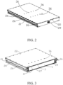
FIG. 2 is an assembly view of a battery pack according to one embodiment of the present disclosure; -
FIG. 3 is a cross-sectional view of a battery pack according to one embodiment of the present disclosure; -
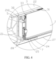
FIG. 4 is a partially enlarged view at A inFIG. 3 ; -
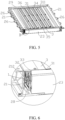
FIG. 5 is another cross-sectional view of a battery pack according to one embodiment of the present disclosure; -
FIG. 6 is a partially enlarged view at B inFIG. 5 ; -
FIG. 7 is a perspective view of a tray according to an embodiment of the present disclosure; -
FIG. 8 is a schematic perspective view of a vapor chamber according to an embodiment of the present disclosure; -
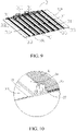
FIG. 9 is a cross-sectional view of a vapor chamber according to one embodiment of the present disclosure; -
FIG. 10 is a partially enlarged view at C inFIG. 9 . -
- 1000. battery pack;
- 1. battery module;
- 2. tray; 21 first edge beam; 211. receiving space; 212. clamping slot; 22. cover plate; 221. through hole; 23. reinforcing beam; 24. support portion; 25. base plate; 26. lug; 27. fender plate; 28. insulating guide plate; 29. second edge beam;
- 3. vapor chamber; 31. cooling tube; 311. heating film; 32. first edge portion; 33. boss; 34. connecting region; 35. bearing region; 36. connecting member; 37. sealing ring;
- 4. thermally conductive structural adhesive; 5. sealing cushion; 6. first structural adhesive; 7. second structural adhesive.
- Embodiments of the present disclosure are described in detail below, and examples of the embodiments are shown in accompanying drawings, where the same or similar elements or the elements having same or similar functions are denoted by the same or similar reference numerals throughout the description. The embodiments that are described below with reference to the accompanying drawings are exemplary, and are only used to interpret the present disclosure and cannot be understood as a limitation to the present disclosure.
- In the description of the present disclosure, it should be understood that, orientations or position relationships indicated by terms such as "center", "longitudinal", "transverse", "length", "width", "thickness", "up", "down", "front", "back", "left", "right", "vertical", "horizontal", "top", "bottom", "inner", "outer", "clockwise", "counterclockwise", "axial", "radial", and "circumferential" are orientations or position relationship shown based on the accompanying drawings, and are merely used for describing the present disclosure and simplifying the description, rather than indicating or implying that the apparatus or element should have a particular orientation or be constructed and operated in a particular orientation, and therefore, should not be construed as a limitation on the present disclosure. In addition, a feature defined to be "first" or "second" may explicitly or implicitly include one or more features. In the description of the present disclosure, unless stated otherwise, the meaning of "a number of" is two or more than two.
- In the description of the present disclosure, it should be noted that unless otherwise explicitly specified or defined, the terms such as "mount", "install", "connect", and "connection" should be understood in a broad sense. For example, the connection may be a fixed connection, a detachable connection, or an integral connection; or the connection may be a mechanical connection or an electrical connection; or the connection may be a direct connection, an indirect connection through an intermediary, or internal communication between two components. A person of ordinary skill in the art may understand the specific meanings of the foregoing terms in the present disclosure according to specific situations.
- A
battery pack 1000 that may be used to power a vehicle according to an embodiment of the present disclosure is described below with reference toFIGS. 1-10 . - The
battery pack 1000 according to an embodiment of the present disclosure includes atray 2 and avapor chamber 3, where thetray 2 includes first edge beams 21 for enclosing a receivingspace 211 having a top opening, thevapor chamber 3 is provided at the top opening of thetray 2, thevapor chamber 3 includes two oppositefirst edge portions 32, and both of the twofirst edge portions 32 are mounted on the first edge beams 21; where one of thefirst edge beam 21 and thefirst edge portion 32 is provided with aclamping slot 212 on an inner surface facing the receivingspace 211, and the other of thefirst edge beam 21 and thefirst edge portion 32 is inserted into theclamping slot 212. - By providing a
clamping slot 212 on one of thefirst edge beam 21 and thefirst edge portion 32, the other one of thefirst edge beam 21 and thefirst edge portion 32 is inserted into theclamping slot 212, so that both thefirst edge portions 32 of thevapor chamber 3 cooperate with the first edge beams 21 enclosing the receivingspace 211, so that thevapor chamber 3 can support the first edge beams 21, and when thetray 2 is extruded or collided, thetray 2 can transmit a force to thevapor chamber 3, thereby increasing the structural strength of thetray 2 and preventing the first edge beams 21 from deforming after being extruded. In addition, since thefirst edge beam 21 and thefirst edge portion 32 are fitted by snap-fitting aclamping slot 212, the reliability of the connection between thefirst edge beam 21 and thefirst edge portion 32 can be improved. - The
battery pack 1000 further includes abattery module 1 placed in the receivingspace 211, and thevapor chamber 3 is located above thebattery module 1. Thebattery module 1 can be provided in the receivingspace 211, and by arranging thevapor chamber 3 at the top opening of the receivingspace 211 and above thebattery module 1, heat exchange can be performed between thevapor chamber 3 and thebattery module 1 so as to heat and/or cool thebattery module 1, thereby satisfying the cooling requirement of thebattery module 1 during charging and discharging and/or satisfying the heating requirement of thebattery module 1 in a low-temperature environment. - For example, in some specific examples, the
battery module 1 may be adhered to thevapor chamber 3, and more specifically, as shown inFIG. 1 , thevapor chamber 3 and thebattery module 1 may be adhered by the thermally conductivestructural adhesive 4, so that the heat exchange efficiency between thevapor chamber 3 and thebattery module 1 may be improved. Of course, the present disclosure is not limited thereto, and for example, thebattery module 1 and thevapor chamber 3 may not be connected to each other, or may be connected to each other by other means, which will not be described in detail herein. - According to the
battery pack 1000 of an embodiment of the present disclosure, by matching bothfirst edge portions 32 of thevapor chamber 3 with the first edge beams 21 enclosing the receivingspace 211, thevapor chamber 3 supports the first edge beams 21, and when thetray 2 is extruded or collided, thetray 2 can transmit a force to thevapor chamber 3, thereby increasing the structural strength of thetray 2 and preventing the first edge beams 21 from deforming after being extruded to achieve the purpose of protecting thebattery module 1 in the receivingspace 211, so that the operation of thebattery module 1 is safe and reliable. In addition, since thevapor chamber 3 is provided at the top opening of thetray 2 where the first edge beams 21 are easily deformed, the first edge beams 21 can be better prevented from being deformed to extrude thebattery module 1. - As shown in
FIGS. 1 ,5 and7 , in some embodiments of the present disclosure, thetray 2 has two first edge beams 21 spaced apart that mate with twofirst edge portions 32, respectively. It can be appreciated that by respectively engaging the twofirst edge portions 32 of thevapor chamber 3 with the two first edge beams 21 of thetray 2, thevapor chamber 3 is supported between the two first edge beams 21 so as to prevent the receivingspace 211 between the two first edge beams 21 from being deformed after being extruded, thereby serving the purpose of protecting thebattery module 1 in the receivingspace 211 to make the operation of thebattery module 1 smooth and reliable. - As shown in
FIGS. 3 and4 , in some embodiments of the present disclosure, theclamping slot 212 is provided on an inner surface of thefirst edge beam 21 facing the receivingspace 211, and thefirst edge portion 32 is inserted into theclamping slot 212 of thefirst edge beam 21. The stability of thevapor chamber 3 supporting thefirst edge beam 21 is thereby improved, and by machining theclamping slot 212 on thefirst edge beam 21, the machining of thevapor chamber 3 can be simplified, which better meets the practical production requirements. - In some embodiments of the present disclosure, the
first edge portion 32 contacts with or abuts against the bottom wall of theclamping slot 212, and thefirst edge portion 32 adheres to a side wall of theclamping slot 212, the stability and reliability of thevapor chamber 3 supporting thefirst edge beam 21 can thereby be improved, and thereby enabling thefirst edge portion 32 to be securely positioned within theclamping slot 212. - The
first edge portion 32 can be adhered to the side wall of theclamping slot 212 so as to further improve the connection strength between thevapor chamber 3 and thetray 2, thereby enabling thevapor chamber 3 to stably support the inside of thefirst edge beam 21. When thetray 2 is extruded or collided, thetray 2 can transmit a force to thevapor chamber 3, thereby increasing the structural strength of thetray 2 and preventing the first edge beams 21 from deforming to extrude thebattery module 1 after being extruded to protect thebattery module 1 in the receivingspace 211 to make the operation of thebattery module 1 safe and reliable. - As shown in
FIGS. 1 to 4 , in some embodiments of the present disclosure, thebattery pack 1000 further includes acover plate 22 located on thevapor chamber 3 and covers the top opening of the receivingspace 211, and a sealingcushion 5 is provided between thecover plate 22 and thevapor chamber 3. The top opening of the receivingspace 211 is sealed by thecover plate 22 to prevent external dust or liquid from entering the receivingspace 211 to affect the operation of thebattery module 1, thereby ensuring smooth and reliable operation of thebattery module 1. - A sealing
cushion 5 is provided between thecover plate 22 and thevapor chamber 3, so that the top opening of the receivingspace 211 can be better sealed by the sealingcushion 5, the sealing performance of the receivingspace 211 can be improved, and the effects of vibration damping and noise reduction can be achieved. - In some embodiments of the present disclosure, the
cover plate 22 is connected to thetray 2 using bolts and extrudes the sealingcushion 5, and the receivingspace 211 is sealed due to the resilient properties of the sealingcushion 5. - As shown in
FIGS. 3 and4 , in some embodiments of the present disclosure, thefirst edge portion 32 is located between the clampingslot 212 and thecover plate 22. Since both ends of thevapor chamber 3 are provided with thefirst edge portions 32, and the two first edge beams 21 of thetray 2 are provided with the clampingslots 212, thevapor chamber 3 can be stably supported between the two first edge beams 21 by extending the twofirst edge portions 32 of thevapor chamber 3 into the clampingslots 212 of the two first edge beams 21, thereby improving the structural strength of thetray 2. - By covering the
vapor chamber 3 with acover plate 22 such that thefirst edge portion 32 of thevapor chamber 3 is provided between the clampingslot 212 and thecover plate 22, thevapor chamber 3 can be clamped by the cooperation of thecover plate 22 and theclamping slot 212 to improve the stability of thevapor chamber 3 in the receivingspace 211, thereby enabling thevapor chamber 3 to be stably supported between the two first edge beams 21 of thetray 2. - As shown in
FIGS. 1 and8-10 , in some embodiments of the present disclosure, the battery pack further includes a number ofcooling tubes 31 provided in sequence on the outer surface of thevapor chamber 3 facing away from the receivingspace 211, and a heater provided between every twoadjacent cooling tubes 31. As can be understood, thebattery module 1 is heated by the heaters to satisfy the heating demand of thebattery module 1 in a low-temperature environment to improve the service life of thebattery module 1. Thebattery module 1 is cooled via thecooling tubes 31 to meet the cooling demand of thebattery module 1 during charging and discharging, and to prevent thebattery module 1 from being operated at a high temperature for a long time, thereby improving the service life of thebattery module 1. - The heaters are provided between every two
adjacent cooling tubes 31 to make full use of the space between the twoadjacent cooling tubes 31, so that the distribution of the heaters and thecooling tubes 31 is relatively uniform, and whether heating or cooling thebattery module 1, heat can be relatively uniformly transferred, the efficiency of improving the temperature is improved, and the structure of thevapor chamber 3 is more compact. - In some embodiments of the present disclosure, the
cooling tubes 31 are integrally aluminium-extruded with thevapor chamber 3, and the heaters are heatingfilms 311. By making thecooling tubes 31 and thevapor chamber 3 as an integrally aluminium-extruded member, theheating films 311 are provided on thevapor chamber 3, so that the connection structure between theheating films 311, thecooling tubes 31 and thevapor chamber 3 is more stable. - As shown in
FIGS. 1 ,8 , and10 , in some embodiments of the present disclosure, a thickness of the coolingtube 31 is greater than a thickness of theheating film 311. - As shown in
FIGS. 1 to 7 , in some embodiments of the present disclosure, thetray 2 further includes two second edge beams 29 provided opposite to each other and a reinforcingbeam 23, the two first edge beams 21 and the two second edge beams 29 together enclose the receivingspace 211, and the reinforcingbeam 23 is provided in parallel with the second edge beams 29. The receivingspace 211 is jointly enclosed by the two first edge beams 21 and the two oppositely provided second edge beams 29 to make the structure defining the receivingspace 211 more stable, prevent the receivingspace 211 from being deformed after being extruded to serve the purpose of protecting thebattery module 1 in the receivingspace 211, and make the operation of thebattery module 1 safe and reliable. - By making the extending direction of the reinforcing
beam 23 parallel to the extending direction of thesecond edge beam 29 so that the reinforcingbeam 23 is supported in the receivingspace 211, the stability in the receivingspace 211 can be further improved, while thevapor chamber 3 can be supported on the reinforcingbeam 23 in the receivingspace 211. - In some embodiments of the present disclosure, as shown in
FIGS. 1 and8-10 , thevapor chamber 3 includes a connectingregion 34 and abearing region 35 other than the connectingregion 34, a thickness of the connectingregion 34 is greater than a thickness of thebearing region 35, and the connectingregion 34 is connected to the reinforcingbeam 23. The mounting stability of thevapor chamber 3 can be improved by connecting the connectingregion 34 of thevapor chamber 3 to the reinforcingbeam 23, and since the thickness of the connectingregion 34 of thevapor chamber 3 is greater than that of thebearing region 35, thevapor chamber 3 can be firmly connected to the reinforcingbeam 23. - In some embodiments of the present disclosure, the connecting
region 34 of thevapor chamber 3 is riveted or screwed to the reinforcingbeam 23. The connectingregion 34 of thevapor chamber 3 may be riveted or screwed to the reinforcingbeam 23 to make the connection between thevapor chamber 3 and the reinforcingbeam 23 more secure and convenient and easy to operate. - As shown in
FIGS. 1 and8-10 , in some embodiments of the present disclosure, a number of connectingregions 34 are provided at intervals on thevapor chamber 3 to improve the strength of thevapor chamber 3 and prevent thevapor chamber 3 from being bent. - As shown in
FIGS. 5 and 6 , in some embodiments of the present disclosure, a parallel direction of the reinforcingbeam 23 and thesecond edge beam 29 is a lengthwise extension direction of the reinforcingbeam 23, twobosses 33 are provided on the inner surface of thevapor chamber 3 facing the receivingspace 211, and the twobosses 33 respectively abut against two end faces of the reinforcingbeam 23 along the parallel direction. By bringing the twobosses 33 of thesecond edge beam 29 into contact with the two reinforcingbeams 23, respectively, thereby preventing thevapor chamber 3 from moving relative to the reinforcingbeams 23, and improving the mounting stability of thevapor chamber 3 and enabling thevapor chamber 3 to stably support thetray 2, thereby further improving the structural strength of thetray 2 and preventing deformation of thetray 2. - As shown in
FIGS. 1 and8-10 , in some embodiments of the present disclosure, thevapor chamber 3 is provided with a connectingmember 36 for connection to a vehicle. The connectingmember 36 is connected to the vehicle body to stably mount thebattery pack 1000 on the vehicle body to improve a vibration mode of thebattery pack 1000. Preferably, the connectingmember 36 may be welded to thevapor chamber 3 to improve the connecting strength of thevapor chamber 3 and the connectingmember 36. The number of the connectingmembers 36 on thevapor chamber 3 may be plural as long as thebattery pack 1000 can be connected to the vehicle body, and the number of the connectingmembers 36 is not limited. - As shown in
FIGS. 1 and8-10 , in some embodiments of the present disclosure, the connectingmember 36 may be a nut and is sleeved with a sealingring 37, acover plate 22 is provided with a throughhole 221, the connectingmember 36 passes through the throughhole 221, and the sealingring 37 seals between thecover plate 22 and the connectingmember 36 so as to ensure the sealing between the connectingmember 36 and the throughhole 221, thereby further ensuring the sealing of the receivingspace 211. The connectingmember 36 may be a bolt or a snap as long as thebattery pack 1000 can be connected to the vehicle body, and the specific structure of the connectingmember 36 is not limited herein. - As shown in
FIGS. 1 to 5 , in some embodiments of the present disclosure, a number oflugs 26 are provided on an outer surface of thetray 2, and a number of bolts are connected to the vehicle body after passing through thelugs 26, so that thebattery pack 1000 is stably connected to the vehicle body, improving the vibration mode of thebattery pack 1000. - As shown in
FIGS. 3 to 6 , in some embodiments of the present disclosure, insulatingguide plates 28 are provided in the receivingspace 211, and the mounting of thebattery module 1 in the receivingspace 211 is guided by the insulatingguide plates 28, so that thebattery module 1 is mounted easier. At the same time, the insulatingguide plates 28 can ensure the insulation between thebattery module 1 and thetray 2, so that the operation of thebattery module 1 is smooth and reliable. Preferably, the insulatingguide plate 28 is a plastic piece. - As shown in
FIG. 4 , in some embodiments of the present disclosure, a bottom of the receivingspace 211 is a bottom of receivingspace 211, thetray 2 further includes abase plate 25 placed on eachsupport portion 24, and thebattery module 1 is placed on thebase plate 25. It will be appreciated that thebase plate 25 is provided on thesupport portion 24 at the bottom of the receivingspace 211, and thebattery module 1 is provided on thebase plate 25, so that thebattery module 1 can be stably provided in the receivingspace 211, and at the same time, when thetray 2 is extruded or collided, the structural strength of thetray 2 is increased by the cooperation of thebase plate 25 and thesupport portion 24, so that thetray 2 is prevented from deforming, thereby protecting thebattery module 1 in the receivingspace 211. - As shown in
FIGS. 1 and4 , in some embodiments of the present disclosure, thebase plate 25 may be connected to the housing of thebattery module 1 by the firststructural adhesive 6 to improve the connection strength between thebase plate 25 and thebattery module 1 so that thebattery module 1 is stably provided in the receivingspace 211. At the same time, even when thebase plate 25 is extruded, since thebase plate 25 is connected to the housing of thebattery module 1, thebase plate 25 merely transmits force to the housing of thebattery module 1 to further improve the smoothness of the operation of thebattery module 1. - As shown in
FIGS. 1 and4 , in some embodiments of the present disclosure, thebottom plate 25 may be connected to thesupport portion 24 via second structural adhesives 7 to ensure the tightness between thebottom plate 25 and thesupport portion 24, thereby further improving the tightness of the receivingspace 211, and also improving the connection strength between thebottom plate 25 and thetray 2, further improving the structural strength of thetray 2 and preventing thetray 2 from deforming. In some embodiments of the present disclosure, the bottom of thetray 2 is further provided with afender plate 27 to further increase the strength of thetray 2. - As shown in
FIGS. 1 to 10 , a vehicle according to an embodiment of the present disclosure includes abattery pack 1000 according to the above embodiment of the present disclosure. - According to the vehicle of an embodiment of the present disclosure, since the operation safety reliability of the
battery module 1 can be improved, the operation safety and reliability of the vehicle can be improved. - In the descriptions of this specification, descriptions using reference terms "an embodiment", "some embodiments", "an exemplary embodiment", "an example", "a specific example", or "some examples" mean that specific characteristics, structures, materials, or features described with reference to the embodiment or example are included in at least one embodiment or example of the present disclosure. In this specification, schematic descriptions of the foregoing terms do not necessarily point at a same embodiment or example. Moreover, the specific features, structures, materials, or characteristics described may be combined in any one or more embodiments or examples in an appropriate manner.
- Although the embodiments of the present disclosure have been shown and described, a person of ordinary skill in the art should understand that various changes, modifications, replacements and variations may be made to the embodiments without departing from the principles and spirit of the present disclosure, and the scope of the present disclosure is as defined by the appended claims and their equivalents.
Claims (15)
- A battery pack for powering a vehicle, comprising a tray and a vapor chamber;wherein the tray comprises first edge beams for enclosing a receiving space having a top opening; the vapor chamber is provided at the top opening of the tray and comprises two opposite first edge portions, and both of the first edge portions are mounted on the first edge beams;and a clamping slot is provided on an inner surface of one of the first edge beam and the first edge portion facing the receiving space, and the other of the first edge beam and the first edge portion is inserted into the clamping slot.
- The battery pack according to claim 1, wherein the tray has two first edge beams spaced apart, and the two first edge beams respectively cooperate with two first edge portions.
- The battery pack according to claim 1 or 2, wherein the clamping slot is provided on an inner surface of the first edge beam facing the receiving space, and the first edge portion is inserted into the clamping slot of the first edge beam.
- The battery pack according to claim 3, wherein the first edge portion contacts with or abuts against bottom wall of the clamping slot, and the first edge portion is adhered to a side wall of the clamping slot.
- The battery pack according to any one of claims 1 to 4, wherein the battery pack further comprises a plurality of cooling tubes provided in sequence on an outer surface of the vapor chamber facing away from the receiving space, and a heater provided between every two adjacent cooling tubes.
- The battery pack according to claim 5, wherein the cooling tubes are integrally aluminum-extruded with the vapor chamber, and the heaters are heating films.
- The battery package according to claim 6, wherein a thickness of the cooling tubes is greater than a thickness of the heating film.
- The battery pack according to any one of claims 2-7, wherein the tray further comprises two second edge beams provided opposite to each other and a reinforcing beam, the first edge beam and the two second edge beams together enclose the receiving space, and the reinforcing beam is parallel with the second edge beams.
- The battery package according to claim 8, wherein the vapor chamber comprises a connecting region and a bearing region other than the connecting region, a thickness of the connecting region is greater than a thickness of the bearing region, and the connecting region is connected to the reinforcing beam.
- The battery pack according to claim 9, wherein the connecting region of the vapor chamber is riveted or screwed to the reinforcing beam.
- The battery pack according to any one of claims 8 to 10, wherein a parallel direction of the reinforcing beam and the second edge beam is a lengthwise extension direction of the reinforcing beam, and two bosses are provided on the inner surface of the vapor chamber facing the receiving space, and the two bosses respectively abut against two end faces of the reinforcing beam along the parallel direction.
- The battery pack according to any one of claims 1 to 11, wherein the vapor chamber is provided with a connecting member for connection to a vehicle.
- The battery pack according to any one of claims 1 to 12, wherein the battery pack further comprises a battery module placed in the receiving space, and the vapor chamber is bonded to the battery module.
- The battery pack according to any one of claims 1 to 13, wherein the battery pack further comprises a cover plate, the cover plate is located on the vapor chamber and covers the top opening of the receiving space, and a sealing cushion is provided between the cover plate and the vapor chamber.
- A vehicle comprising the battery pack according to any one of claims 1 to 14.
Applications Claiming Priority (2)
| Application Number | Priority Date | Filing Date | Title |
|---|---|---|---|
| CN202010517961.5A CN113851768B (en) | 2020-06-09 | 2020-06-09 | Battery Packs and Vehicles |
| PCT/CN2021/083924 WO2021248986A1 (en) | 2020-06-09 | 2021-03-30 | Battery pack and vehicle |
Publications (3)
| Publication Number | Publication Date |
|---|---|
| EP4145604A1 true EP4145604A1 (en) | 2023-03-08 |
| EP4145604A4 EP4145604A4 (en) | 2024-10-30 |
| EP4145604B1 EP4145604B1 (en) | 2026-05-06 |
Family
ID=78845179
Family Applications (1)
| Application Number | Title | Priority Date | Filing Date |
|---|---|---|---|
| EP21823055.5A Active EP4145604B1 (en) | 2020-06-09 | 2021-03-30 | Battery pack and vehicle |
Country Status (6)
| Country | Link |
|---|---|
| US (1) | US12603345B2 (en) |
| EP (1) | EP4145604B1 (en) |
| JP (1) | JP7579363B2 (en) |
| KR (1) | KR102824881B1 (en) |
| CN (1) | CN113851768B (en) |
| WO (1) | WO2021248986A1 (en) |
Cited By (1)
| Publication number | Priority date | Publication date | Assignee | Title |
|---|---|---|---|---|
| EP4478506A1 (en) * | 2023-06-12 | 2024-12-18 | Hyundai Mobis Co., Ltd. | Watertight battery lower case and manufacturing method thereof |
Families Citing this family (10)
| Publication number | Priority date | Publication date | Assignee | Title |
|---|---|---|---|---|
| US11996576B2 (en) * | 2020-07-03 | 2024-05-28 | Teijin Automotive Technologies, Inc. | Impact resistant frame of battery containment system |
| CN116766935A (en) * | 2022-03-11 | 2023-09-19 | 宇通客车股份有限公司 | Passenger car with battery compartment bottom collision protection structure |
| KR20240119089A (en) * | 2022-03-14 | 2024-08-06 | 비와이디 컴퍼니 리미티드 | Battery trays, battery packs and vehicles |
| CN217158490U (en) * | 2022-03-14 | 2022-08-09 | 比亚迪股份有限公司 | Battery pack and vehicle |
| CN217134566U (en) * | 2022-03-14 | 2022-08-05 | 比亚迪股份有限公司 | Battery trays, battery packs and vehicles |
| EP4456265A4 (en) * | 2022-07-29 | 2025-05-14 | Contemporary Amperex Technology (Hong Kong) Limited | BATTERY AND ELECTRICAL DEVICE |
| CN118572280A (en) * | 2023-02-28 | 2024-08-30 | 比亚迪股份有限公司 | Battery box, battery pack and vehicle |
| KR102628969B1 (en) * | 2023-09-27 | 2024-01-24 | 주식회사케이에스엠 | Electric vehicle battery case manufacturing method |
| CN118231923B (en) * | 2024-04-30 | 2026-01-02 | 奇瑞新能源汽车股份有限公司 | Battery packs and vehicles |
| CN120199962B (en) * | 2025-05-26 | 2025-09-09 | 比亚迪股份有限公司 | Battery pack, vehicle and electric equipment |
Family Cites Families (27)
| Publication number | Priority date | Publication date | Assignee | Title |
|---|---|---|---|---|
| EP2355204B1 (en) * | 2010-02-02 | 2012-10-10 | Dana Canada Corporation | Conformal heat exchanger for battery cell stack |
| WO2011119669A2 (en) | 2010-03-23 | 2011-09-29 | A123 Systems, Inc. | System and method for controlling a battery pack output contactor |
| EP2854212A1 (en) * | 2013-09-30 | 2015-04-01 | Behr France Rouffach SAS | Heating and cooling device for a battery |
| CN203589102U (en) * | 2013-11-12 | 2014-05-07 | 鹤山健豪灯饰企业有限公司 | Battery box with waterproof function |
| EP3098896A1 (en) * | 2015-05-28 | 2016-11-30 | Mahle International GmbH | Temperature control device for temperature controlling a battery, in particular of a motor vehicle |
| CN105914428A (en) | 2016-04-19 | 2016-08-31 | 苏州汉纳材料科技有限公司 | Temperature equilibrium structure applicable to energy storage device and device |
| CN206412396U (en) * | 2017-01-23 | 2017-08-15 | 湖北汽车工业学院 | A kind of lightweight battery case based on lattice structure |
| US10886513B2 (en) * | 2017-05-16 | 2021-01-05 | Shape Corp. | Vehicle battery tray having tub-based integration |
| CN206849903U (en) * | 2017-06-06 | 2018-01-05 | 北京新能源汽车股份有限公司 | Battery shell and lifting lug thereof |
| CN110998897A (en) * | 2017-08-23 | 2020-04-10 | 蒂森克虏伯钢铁欧洲股份公司 | Temperature control device for battery module, battery case, and temperature control method for battery module |
| CN207338482U (en) * | 2017-10-16 | 2018-05-08 | 天津世仓工业设备有限公司 | A kind of battery case used for electric vehicle with safeguard function |
| CN207409607U (en) * | 2017-10-31 | 2018-05-25 | 昆山正国新能源动力电池有限公司 | A kind of lithium ion battery module |
| CN208570855U (en) | 2018-03-13 | 2019-03-01 | 北京微焓科技有限公司 | Battery cooling component and include the battery cooling component electric automobile cooling system |
| CN208433488U (en) * | 2018-05-24 | 2019-01-25 | 中信国安盟固利动力科技有限公司 | A kind of lithium battery mould group having heat dissipation and heating function |
| CN208986036U (en) * | 2018-08-18 | 2019-06-14 | 江西赣锋电池科技有限公司 | A kind of lithium battery pack cabinet |
| FR3085545B1 (en) * | 2018-09-04 | 2025-12-19 | Exoes | ELECTRICAL MODULE COMPRISING A MULTIPLE BATTERY CELLS IMMERSED IN A DIELECTRIC FLUID |
| CN209312836U (en) * | 2018-12-14 | 2019-08-27 | 蜂巢能源科技有限公司 | Case and battery pack |
| US12230820B2 (en) * | 2019-01-09 | 2025-02-18 | Byd Company Limited | Power battery pack and electric vehicle |
| CN111668405A (en) * | 2019-03-08 | 2020-09-15 | 比亚迪股份有限公司 | Battery pack and vehicle having the same |
| CN209822722U (en) * | 2019-05-20 | 2019-12-20 | 深圳市旻泰电子科技有限公司 | Waterproof battery protection circuit board |
| CN209822833U (en) * | 2019-06-21 | 2019-12-20 | 比亚迪股份有限公司 | Power battery pack and vehicle with same |
| CN209747613U (en) * | 2019-06-28 | 2019-12-06 | 江苏时代新能源科技有限公司 | battery module |
| CN210073956U (en) * | 2019-06-28 | 2020-02-14 | 蜂巢能源科技有限公司 | Lower casing boundary beam, lower casing and battery package |
| CN210073974U (en) * | 2019-08-10 | 2020-02-14 | 杭州捷能科技有限公司 | Battery pack resistant to ground impact |
| CN210403972U (en) * | 2019-08-23 | 2020-04-24 | 比亚迪股份有限公司 | Heat exchange plate assembly of battery pack and battery assembly having the same, electric vehicle |
| CN210535786U (en) * | 2019-09-05 | 2020-05-15 | 安徽舟之航电池有限公司 | Battery package PTC heater mounting structure |
| CN211543575U (en) * | 2019-11-19 | 2020-09-22 | 南京熊猫电子制造有限公司 | Trolley structure for detecting turnover of screen |
-
2020
- 2020-06-09 CN CN202010517961.5A patent/CN113851768B/en active Active
-
2021
- 2021-03-30 KR KR1020227044896A patent/KR102824881B1/en active Active
- 2021-03-30 EP EP21823055.5A patent/EP4145604B1/en active Active
- 2021-03-30 JP JP2022575933A patent/JP7579363B2/en active Active
- 2021-03-30 US US18/009,129 patent/US12603345B2/en active Active
- 2021-03-30 WO PCT/CN2021/083924 patent/WO2021248986A1/en not_active Ceased
Cited By (1)
| Publication number | Priority date | Publication date | Assignee | Title |
|---|---|---|---|---|
| EP4478506A1 (en) * | 2023-06-12 | 2024-12-18 | Hyundai Mobis Co., Ltd. | Watertight battery lower case and manufacturing method thereof |
Also Published As
| Publication number | Publication date |
|---|---|
| CN113851768B (en) | 2023-01-06 |
| KR20230015410A (en) | 2023-01-31 |
| CN113851768A (en) | 2021-12-28 |
| KR102824881B1 (en) | 2025-06-26 |
| JP2023528962A (en) | 2023-07-06 |
| WO2021248986A1 (en) | 2021-12-16 |
| EP4145604A4 (en) | 2024-10-30 |
| US12603345B2 (en) | 2026-04-14 |
| JP7579363B2 (en) | 2024-11-07 |
| US20230231223A1 (en) | 2023-07-20 |
| EP4145604B1 (en) | 2026-05-06 |
Similar Documents
| Publication | Publication Date | Title |
|---|---|---|
| EP4145604B1 (en) | Battery pack and vehicle | |
| US11563255B2 (en) | Power supply device, and separator for power supply device | |
| US12597670B2 (en) | Automobile with battery pack installed over underbody frame | |
| KR102703855B1 (en) | Battery module and Manufacturing method of the same | |
| US11139515B2 (en) | Battery module having heat conduction pad | |
| KR101991925B1 (en) | Battery Module Comprising Cartridge Having Gripping Part | |
| JP5723991B2 (en) | Battery pack with compact structure | |
| JP7556985B2 (en) | Battery packs and electric vehicles | |
| EP4425673A1 (en) | Power battery pack and electric device | |
| US11721856B2 (en) | Battery pack for a vehicle | |
| KR20130090700A (en) | Bus bar with novel structure | |
| KR20220101692A (en) | Battery packs and electric vehicles | |
| KR20130086678A (en) | Battery module with novel structure | |
| JP2013539175A (en) | Battery module and battery pack including the same | |
| CN112993474A (en) | Battery pack lower box body and battery pack | |
| EP4287360B1 (en) | Battery module, battery pack comprising battery module, and vehicle comprising battery pack | |
| CN113844247B (en) | A battery pack and electric vehicle | |
| CN223956662U (en) | Battery packs and electrical devices | |
| CN220491921U (en) | Control assembly and battery system | |
| CN121983729A (en) | End plate assembly, battery pack and electric equipment | |
| CN113851770A (en) | A kind of battery pack and electric vehicle |
Legal Events
| Date | Code | Title | Description |
|---|---|---|---|
| STAA | Information on the status of an ep patent application or granted ep patent |
Free format text: STATUS: THE INTERNATIONAL PUBLICATION HAS BEEN MADE |
|
| PUAI | Public reference made under article 153(3) epc to a published international application that has entered the european phase |
Free format text: ORIGINAL CODE: 0009012 |
|
| STAA | Information on the status of an ep patent application or granted ep patent |
Free format text: STATUS: REQUEST FOR EXAMINATION WAS MADE |
|
| 17P | Request for examination filed |
Effective date: 20221201 |
|
| AK | Designated contracting states |
Kind code of ref document: A1 Designated state(s): AL AT BE BG CH CY CZ DE DK EE ES FI FR GB GR HR HU IE IS IT LI LT LU LV MC MK MT NL NO PL PT RO RS SE SI SK SM TR |
|
| DAV | Request for validation of the european patent (deleted) | ||
| DAX | Request for extension of the european patent (deleted) | ||
| A4 | Supplementary search report drawn up and despatched |
Effective date: 20241001 |
|
| RIC1 | Information provided on ipc code assigned before grant |
Ipc: H01M 50/271 20210101ALI20240925BHEP Ipc: H01M 10/6556 20140101ALI20240925BHEP Ipc: H01M 10/613 20140101ALI20240925BHEP Ipc: H01M 10/625 20140101ALI20240925BHEP Ipc: H01M 10/617 20140101ALI20240925BHEP Ipc: H01M 50/204 20210101AFI20240925BHEP |
|
| GRAP | Despatch of communication of intention to grant a patent |
Free format text: ORIGINAL CODE: EPIDOSNIGR1 |
|
| STAA | Information on the status of an ep patent application or granted ep patent |
Free format text: STATUS: GRANT OF PATENT IS INTENDED |
|
| RIC1 | Information provided on ipc code assigned before grant |
Ipc: H01M 50/204 20210101AFI20251125BHEP Ipc: H01M 50/271 20210101ALI20251125BHEP Ipc: H01M 10/6556 20140101ALI20251125BHEP Ipc: H01M 10/613 20140101ALI20251125BHEP Ipc: H01M 10/625 20140101ALI20251125BHEP Ipc: H01M 10/617 20140101ALI20251125BHEP Ipc: H01M 10/615 20140101ALI20251125BHEP Ipc: H01M 10/647 20140101ALI20251125BHEP Ipc: H01M 10/6552 20140101ALI20251125BHEP Ipc: H01M 10/6554 20140101ALI20251125BHEP Ipc: H01M 10/6568 20140101ALI20251125BHEP Ipc: H01M 50/209 20210101ALI20251125BHEP Ipc: H01M 50/224 20210101ALI20251125BHEP Ipc: H01M 50/24 20210101ALI20251125BHEP Ipc: H01M 50/242 20210101ALI20251125BHEP Ipc: H01M 50/244 20210101ALI20251125BHEP Ipc: H01M 50/249 20210101ALI20251125BHEP Ipc: H01M 50/264 20210101ALI20251125BHEP |
|
| INTG | Intention to grant announced |
Effective date: 20251212 |
|
| GRAS | Grant fee paid |
Free format text: ORIGINAL CODE: EPIDOSNIGR3 |
|
| P01 | Opt-out of the competence of the unified patent court (upc) registered |
Free format text: CASE NUMBER: UPC_APP_0003375_4145604/2026 Effective date: 20260130 |
|
| GRAA | (expected) grant |
Free format text: ORIGINAL CODE: 0009210 |
|
| STAA | Information on the status of an ep patent application or granted ep patent |
Free format text: STATUS: THE PATENT HAS BEEN GRANTED |