EP4145598B1 - Battery cell and battery module including same - Google Patents
Battery cell and battery module including same Download PDFInfo
- Publication number
- EP4145598B1 EP4145598B1 EP21889528.2A EP21889528A EP4145598B1 EP 4145598 B1 EP4145598 B1 EP 4145598B1 EP 21889528 A EP21889528 A EP 21889528A EP 4145598 B1 EP4145598 B1 EP 4145598B1
- Authority
- EP
- European Patent Office
- Prior art keywords
- battery cell
- battery
- lead
- lead film
- gas discharge
- Prior art date
- Legal status (The legal status is an assumption and is not a legal conclusion. Google has not performed a legal analysis and makes no representation as to the accuracy of the status listed.)
- Active
Links
Images



Classifications
-
- H—ELECTRICITY
- H01—ELECTRIC ELEMENTS
- H01M—PROCESSES OR MEANS, e.g. BATTERIES, FOR THE DIRECT CONVERSION OF CHEMICAL ENERGY INTO ELECTRICAL ENERGY
- H01M50/00—Constructional details or processes of manufacture of the non-active parts of electrochemical cells other than fuel cells, e.g. hybrid cells
- H01M50/10—Primary casings; Jackets or wrappings
- H01M50/172—Arrangements of electric connectors penetrating the casing
-
- H—ELECTRICITY
- H01—ELECTRIC ELEMENTS
- H01M—PROCESSES OR MEANS, e.g. BATTERIES, FOR THE DIRECT CONVERSION OF CHEMICAL ENERGY INTO ELECTRICAL ENERGY
- H01M50/00—Constructional details or processes of manufacture of the non-active parts of electrochemical cells other than fuel cells, e.g. hybrid cells
- H01M50/30—Arrangements for facilitating escape of gases
- H01M50/342—Non-re-sealable arrangements
- H01M50/3425—Non-re-sealable arrangements in the form of rupturable membranes or weakened parts, e.g. pierced with the aid of a sharp member
-
- H—ELECTRICITY
- H01—ELECTRIC ELEMENTS
- H01M—PROCESSES OR MEANS, e.g. BATTERIES, FOR THE DIRECT CONVERSION OF CHEMICAL ENERGY INTO ELECTRICAL ENERGY
- H01M50/00—Constructional details or processes of manufacture of the non-active parts of electrochemical cells other than fuel cells, e.g. hybrid cells
- H01M50/10—Primary casings; Jackets or wrappings
- H01M50/102—Primary casings; Jackets or wrappings characterised by their shape or physical structure
- H01M50/105—Pouches or flexible bags
-
- H—ELECTRICITY
- H01—ELECTRIC ELEMENTS
- H01M—PROCESSES OR MEANS, e.g. BATTERIES, FOR THE DIRECT CONVERSION OF CHEMICAL ENERGY INTO ELECTRICAL ENERGY
- H01M50/00—Constructional details or processes of manufacture of the non-active parts of electrochemical cells other than fuel cells, e.g. hybrid cells
- H01M50/10—Primary casings; Jackets or wrappings
- H01M50/116—Primary casings; Jackets or wrappings characterised by the material
- H01M50/124—Primary casings; Jackets or wrappings characterised by the material having a layered structure
- H01M50/1243—Primary casings; Jackets or wrappings characterised by the material having a layered structure characterised by the internal coating on the casing
-
- H—ELECTRICITY
- H01—ELECTRIC ELEMENTS
- H01M—PROCESSES OR MEANS, e.g. BATTERIES, FOR THE DIRECT CONVERSION OF CHEMICAL ENERGY INTO ELECTRICAL ENERGY
- H01M50/00—Constructional details or processes of manufacture of the non-active parts of electrochemical cells other than fuel cells, e.g. hybrid cells
- H01M50/10—Primary casings; Jackets or wrappings
- H01M50/172—Arrangements of electric connectors penetrating the casing
- H01M50/174—Arrangements of electric connectors penetrating the casing adapted for the shape of the cells
- H01M50/178—Arrangements of electric connectors penetrating the casing adapted for the shape of the cells for pouch or flexible bag cells
-
- H—ELECTRICITY
- H01—ELECTRIC ELEMENTS
- H01M—PROCESSES OR MEANS, e.g. BATTERIES, FOR THE DIRECT CONVERSION OF CHEMICAL ENERGY INTO ELECTRICAL ENERGY
- H01M50/00—Constructional details or processes of manufacture of the non-active parts of electrochemical cells other than fuel cells, e.g. hybrid cells
- H01M50/10—Primary casings; Jackets or wrappings
- H01M50/183—Sealing members
-
- H—ELECTRICITY
- H01—ELECTRIC ELEMENTS
- H01M—PROCESSES OR MEANS, e.g. BATTERIES, FOR THE DIRECT CONVERSION OF CHEMICAL ENERGY INTO ELECTRICAL ENERGY
- H01M50/00—Constructional details or processes of manufacture of the non-active parts of electrochemical cells other than fuel cells, e.g. hybrid cells
- H01M50/10—Primary casings; Jackets or wrappings
- H01M50/183—Sealing members
- H01M50/184—Sealing members characterised by their shape or structure
-
- H—ELECTRICITY
- H01—ELECTRIC ELEMENTS
- H01M—PROCESSES OR MEANS, e.g. BATTERIES, FOR THE DIRECT CONVERSION OF CHEMICAL ENERGY INTO ELECTRICAL ENERGY
- H01M50/00—Constructional details or processes of manufacture of the non-active parts of electrochemical cells other than fuel cells, e.g. hybrid cells
- H01M50/10—Primary casings; Jackets or wrappings
- H01M50/183—Sealing members
- H01M50/19—Sealing members characterised by the material
-
- H—ELECTRICITY
- H01—ELECTRIC ELEMENTS
- H01M—PROCESSES OR MEANS, e.g. BATTERIES, FOR THE DIRECT CONVERSION OF CHEMICAL ENERGY INTO ELECTRICAL ENERGY
- H01M50/00—Constructional details or processes of manufacture of the non-active parts of electrochemical cells other than fuel cells, e.g. hybrid cells
- H01M50/10—Primary casings; Jackets or wrappings
- H01M50/183—Sealing members
- H01M50/19—Sealing members characterised by the material
- H01M50/193—Organic material
-
- H—ELECTRICITY
- H01—ELECTRIC ELEMENTS
- H01M—PROCESSES OR MEANS, e.g. BATTERIES, FOR THE DIRECT CONVERSION OF CHEMICAL ENERGY INTO ELECTRICAL ENERGY
- H01M50/00—Constructional details or processes of manufacture of the non-active parts of electrochemical cells other than fuel cells, e.g. hybrid cells
- H01M50/30—Arrangements for facilitating escape of gases
-
- H—ELECTRICITY
- H01—ELECTRIC ELEMENTS
- H01M—PROCESSES OR MEANS, e.g. BATTERIES, FOR THE DIRECT CONVERSION OF CHEMICAL ENERGY INTO ELECTRICAL ENERGY
- H01M50/00—Constructional details or processes of manufacture of the non-active parts of electrochemical cells other than fuel cells, e.g. hybrid cells
- H01M50/30—Arrangements for facilitating escape of gases
- H01M50/35—Gas exhaust passages comprising elongated, tortuous or labyrinth-shaped exhaust passages
- H01M50/367—Internal gas exhaust passages forming part of the battery cover or case; Double cover vent systems
-
- H—ELECTRICITY
- H01—ELECTRIC ELEMENTS
- H01M—PROCESSES OR MEANS, e.g. BATTERIES, FOR THE DIRECT CONVERSION OF CHEMICAL ENERGY INTO ELECTRICAL ENERGY
- H01M50/00—Constructional details or processes of manufacture of the non-active parts of electrochemical cells other than fuel cells, e.g. hybrid cells
- H01M50/30—Arrangements for facilitating escape of gases
- H01M50/394—Gas-pervious parts or elements
-
- H—ELECTRICITY
- H01—ELECTRIC ELEMENTS
- H01M—PROCESSES OR MEANS, e.g. BATTERIES, FOR THE DIRECT CONVERSION OF CHEMICAL ENERGY INTO ELECTRICAL ENERGY
- H01M50/00—Constructional details or processes of manufacture of the non-active parts of electrochemical cells other than fuel cells, e.g. hybrid cells
- H01M50/50—Current conducting connections for cells or batteries
- H01M50/543—Terminals
- H01M50/552—Terminals characterised by their shape
- H01M50/553—Terminals adapted for prismatic, pouch or rectangular cells
- H01M50/557—Plate-shaped terminals
-
- H—ELECTRICITY
- H01—ELECTRIC ELEMENTS
- H01M—PROCESSES OR MEANS, e.g. BATTERIES, FOR THE DIRECT CONVERSION OF CHEMICAL ENERGY INTO ELECTRICAL ENERGY
- H01M50/00—Constructional details or processes of manufacture of the non-active parts of electrochemical cells other than fuel cells, e.g. hybrid cells
- H01M50/10—Primary casings; Jackets or wrappings
- H01M50/183—Sealing members
- H01M50/186—Sealing members characterised by the disposition of the sealing members
- H01M50/188—Sealing members characterised by the disposition of the sealing members the sealing members being arranged between the lid and terminal
-
- Y—GENERAL TAGGING OF NEW TECHNOLOGICAL DEVELOPMENTS; GENERAL TAGGING OF CROSS-SECTIONAL TECHNOLOGIES SPANNING OVER SEVERAL SECTIONS OF THE IPC; TECHNICAL SUBJECTS COVERED BY FORMER USPC CROSS-REFERENCE ART COLLECTIONS [XRACs] AND DIGESTS
- Y02—TECHNOLOGIES OR APPLICATIONS FOR MITIGATION OR ADAPTATION AGAINST CLIMATE CHANGE
- Y02E—REDUCTION OF GREENHOUSE GAS [GHG] EMISSIONS, RELATED TO ENERGY GENERATION, TRANSMISSION OR DISTRIBUTION
- Y02E60/00—Enabling technologies; Technologies with a potential or indirect contribution to GHG emissions mitigation
- Y02E60/10—Energy storage using batteries
Definitions
- the present disclosure relates to a battery cell and a battery module including the same, and more particularly, to a battery cell with improved external emission of gas generated inside the battery cell, and a battery module including the same.
- secondary batteries are of great interest as energy sources not only for mobile devices such as mobile phones, digital cameras, notebooks and wearable devices, but also for power devices such as electric bicycles, electric vehicles and hybrid electric vehicles.
- these secondary batteries are classified into a cylindrical battery and a prismatic battery in which a battery assembly is included in a cylindrical or prismatic metal can, and a pouch-type battery in which the battery assembly is included in a pouch-type case of an aluminum laminate sheet.
- the battery assembly included in the battery case is a power element including a positive electrode, a negative electrode, and a separator interposed between the positive electrode and the negative electrode, and capable of charging and discharging, and is classified into a jelly-roll type in which long sheet-type positive and negative electrodes coated with an active material are wound with a separator being interposed therebetween, and a stack type in which a plurality of positive and negative electrodes are sequentially stacked with a separator being interposed therebetween.
- a pouch-type battery in which a stack-type or stack/folding-type battery assembly is included in a pouch-type battery case made of an aluminum laminate sheet is being used more and more due to low manufacturing cost, small weight, and easy deformation.
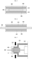
- FIG. 1 is a top view showing a conventional battery cell.
- FIG. 2 is a cross-sectional view, taken along the axis a-a' of FIG. 1 .
- a conventional battery cell 10 includes a battery case 20 having an accommodation portion 21 in which a battery assembly 11 is mounted, and a sealing portion 25 formed by sealing an outer periphery thereof by heat fusion.
- the battery cell 10 includes an electrode lead 30 protruding out of the battery case 20 via the sealing portion 25, and a lead film 40 is positioned between upper and lower portions of the electrode lead 30 and the sealing portion 25.
- CN 107 925 033 A concerns a battery cell with a gas discharge pipe embedded in a lead film away from an electrode lead
- US 10 141 553 B2 concerns a battery cell with gas discharge portion comprising slits in lead films corresponding to a slit in an electrode lead
- WO 2014/109481 A1 concerns a battery cell with gas discharge portion opened towards the exterior or the case of the battery cell.
- the present disclosure is designed to solve the problems of the related art, and therefore the present disclosure is directed to providing a battery cell with improved external emission of gas generated inside the battery cell, and a battery module including the same.
- a battery cell comprising: a battery case having an accommodation portion in which a battery assembly is mounted, and a sealing portion formed by sealing an outer periphery thereof by heat fusion; an electrode lead electrically connected to an electrode tab included in the battery assembly and protruding out of the battery case via the sealing portion; and a lead film positioned at a portion corresponding to the sealing portion in at least one of an upper portion and a lower portion of the electrode lead, wherein the lead film includes a gas discharge portion formed to extend from the inside of the battery case to the outside of the battery case, and the gas discharge portion is opened toward the inside of the battery case.
- a front surface and both side surfaces of the gas discharge portion based on a protruding direction of the electrode lead are closed.
- the battery cell may further comprise an inner layer configured to cover at least a part of a surface of the gas discharge portion.
- a material of the inner layer may have a higher melting point compared to a material of the lead film and may not react with an electrolytic solution.
- the lead film may comprise a polyolefin-based material, and the inner layer may contain at least one of polyolefin-based, fluorine-based and porous ceramic-based materials.
- the lead film may have a greater width than the electrode lead.
- the lead film may have a greater length than the sealing portion and have a smaller length than the electrode lead.
- the gas discharge portion may have a greater width than the electrode lead.
- the lead film may include a first lead film and a second lead film, the first lead film may be positioned at an upper portion of the electrode lead, and the second lead film may be positioned at a lower portion of the electrode lead.
- the electrode lead may be positioned between the first lead film and the second lead film, and the first lead film and the second lead film may be connected to each other.
- An end of the gas discharge portion formed within the lead film may be positioned outer than an outer surface of the battery case.
- An end of the gas discharge portion opened toward the inside of the battery case may be positioned inner than an inner surface of the battery case.
- a battery module comprising the battery cell described above.
- the present disclosure provides a battery cell including an electrode lead to which a lead film having a maximum penetration area is attached, and a battery module including the same, it is possible to improve the external emission of gas generated inside the battery cell.
- top view it means that the target part is viewed from above, and when referring to “cross-sectional view”, it means that a vertically-cut section of the target part is viewed from a side.
- a pouch battery cell 100 according to an embodiment of the present disclosure will be described. However, here, the description will be made based on one side surface of both side surfaces of the pouch battery cell 100, but it is not necessarily limited thereto, and the same or similar contents may be described in the case of the other side surface.
- FIG. 3 is a top view showing a battery cell according to this embodiment.
- the battery cell 100 includes a battery case 200, an electrode lead 300, and a lead film 400.
- the battery case 200 includes an accommodation portion 210 in which a battery assembly 110 is mounted, and a sealing portion 250 formed by sealing an outer periphery thereof by heat fusion.
- the battery case 200 may be a laminate sheet including a resin layer and a metal layer. More specifically, the battery case 200 may be made of a laminate sheet, and may include an outer resin layer forming the outermost layer, a barrier metal layer preventing penetration of materials, and an inner resin layer for sealing.
- the battery assembly 110 may have a structure of a jelly-roll type (winding type), a stack type (lamination type), or a composite type (stack/folding type). More specifically, the battery assembly 110 may include a positive electrode, a negative electrode, and a separator disposed therebetween.
- the electrode lead 300 and the lead film 400 will be mainly described.
- FIG. 4 is a perspective view showing an electrode lead included in the battery cell of FIG. 3 .
- the electrode lead 300 is electrically connected to an electrode tab (not shown) included in the battery assembly 110, and protrudes out of the battery case 200 via the sealing portion 250.
- the lead film 400 is positioned at a portion corresponding to the sealing portion 250 in at least one of an upper portion and a lower portion of the electrode lead 300. Accordingly, the lead film 400 may improve the sealing properties of the sealing portion 250 and the electrode lead 300 while preventing a short circuit from occurring in the electrode lead 300 during thermal fusion.
- the lead film 400 may have a greater width than the electrode lead 300.
- the lead film may have a greater length than the sealing portion and have a smaller length than the electrode lead. Accordingly, the lead film 400 may prevent the side surface of the electrode lead 300 from being exposed to the outside without interfering with the electrical connection of the electrode lead 300.
- the lead film 400 may include a first lead film and a second lead film, the first lead film may be positioned at an upper portion of the electrode lead 300, and the second lead film may be positioned at a lower portion of the electrode lead 300.
- the electrode lead 300 may be heat-fused together with the sealing portion 250 in a state of being located between the first lead film and the second lead film, so that the first lead film and the second lead film may be connected to each other.
- the lead film 400 may prevent the side surface of the electrode lead 300 from being exposed to the outside, while improving the sealing properties of the sealing portion 250 and the electrode lead 300.
- FIG. 5 is a cross-sectional view, taken along the axis c-c' of FIG. 4 .
- FIG. 6 is a cross-sectional view, taken along the axis d-d' of FIG. 4 .
- FIG. 7 is a cross-sectional view, taken along the axis b-b' of FIG. 3 .
- the lead film 400 includes a gas discharge portion 450 formed to extend from the inside of the battery case 200 to the outside of the battery case 200, and the gas discharge portion 450 is opened toward the inside of the battery case 200.
- a front surface and both side surfaces of the gas discharge portion 450 based on a protruding direction of the electrode lead 300 are closed.
- the gas discharge portion 450 may refer to a portion in which the remaining surfaces of the lead film 400 other than for the surface opened toward the inside of the battery case 200 are not adhered with each other.
- the gas discharge portion 450 may have a greater width than the electrode lead 300.
- the gas generated inside the battery case 200 flows in the gas discharge portion 450 of the lead film 400.
- the pressure of the lead film 400 is higher than a predetermined pressure
- the gas generated inside the battery case 200 passes through the gas discharge portion 450 to be discharged to the outside.
- the lead film 400 discharges a large amount of gas.
- the lead film 400 may further include an inner layer 410 that covers at least a part of the surface of the gas discharge portion 450. More preferably, the inner layer 410 may cover the entire surface of the gas discharge portion 450.
- the inner layer 410 may be coated on the gas discharge portion 450 or may be manufactured as a separate film and attached to the gas discharge portion 450.
- the gas discharge portion 450 may be preserved without being heat-fused by the inner layer 410.
- the inner layer 410 may be made of a material having a higher melting point compared to the material of the lead film 400.
- the inner layer 410 may be made of a material that does not react with an electrolytic solution contained in the battery case 300.
- the lead film 400 may include a polyolefin-based material
- the inner layer 410 may include at least one of a polyolefin-based material, a fluorine-based material, and a porous ceramic-based material.
- the inner layer 410 may include a getter material to increase gas permeability while minimizing water permeability.
- the getter material may be calcium oxide (CaO), barium oxide (BaO), lithium chloride (LiCl), silica (SiO 2 ), or the like, but is not limited thereto, and any material reacting with water (H 2 O) may be used.
- the inner layer 410 since the inner layer 410 is made of the above-described material, the inner layer 410 does not react separately with the electrolytic solution and does not cause heat fusion, thermal deformation, or the like during the high-temperature thermal fusion process, so that the gas discharge portion 450 may be kept blank. That is, the inner surface of the gas discharge portion 450 may be maintained in a non-adhesive state.
- the inner surfaces of the gas discharge portion 450 may be spaced apart from each other, so that the gas introduced into the gas discharge portion 450 may be easily discharged to the outside.
- the lead film 400 since the lead film 400 is made of the above-described material, the lead film 400 may maintain the airtightness of the battery cell 100 and also prevent leakage of the internal electrolytic solution.
- an end of the gas discharge portion 450 formed within the lead film 400 may be positioned outer than the outer surface of the battery case 200.
- an end of the gas discharge portion 450 that is opened toward the inside of the battery case 200 may be positioned inner than the inner surface of the battery case 200.
- FIG. 8 is a diagram showing the flow of gas generated inside the battery cell of FIG. 7 and discharged to the outside.
- the gas generated inside the battery cell 100 of FIG. 7 may flow toward the gas discharge portion 450 of the lead film 400.
- the gas discharge portion 450 may be expanded upward and downward compared to FIG. 7 by the gas inside the battery cell 100.
- the gas inside the battery cell 100 exceeds a predetermined pressure, the gas inside the battery cell 100 may be discharged to the outside through the gas discharge portion 450.
- the permeation area of the gas inside the battery cell 100 is also maximized, and thus the amount of the gas discharged to the outside may also be maximized.
- the battery module described above and the battery pack including the same may be applied to various devices. These devices may be transportation means such as electric bicycles, electric vehicles, hybrid electric vehicles, and the like, but the present disclosure is not limited thereto, and the present disclosure may be applied various devices that can use a battery module and a battery pack including the same.
- a battery cell including a battery case having an accommodation portion in which a battery assembly was mounted and a sealing portion formed by sealing an outer periphery of the battery case by heat fusion was manufactured.
- an electrode tab included in the battery assembly was electrically connected to an electrode lead, and the electrode lead protruded out of the battery case via the sealing portion.
- a lead film was attached to a position corresponding to the sealing portion in an upper portion of the electrode lead, and a gas discharge portion extending from the inside of the battery case to the outside of the battery case was formed in the lead film.
- a battery cell was manufactured in the same manner as in the example, except that a separate gas discharge portion was not formed in the lead film.
- CT was taken centered on the sealing portion where the lead film and the electrode lead were located, and a CT image of the corresponding portion was obtained as shown in FIG. 9 .
- FIG. 9 is a diagram showing a cross section of a battery cell according to Experimental Example 1.
- FIG. 9(a) is a CT image of a cross-section of the lead film and electrode lead before the internal pressure of the battery cell of the example is increased
- FIG. 9(b) is a CT image of a cross-section of the lead film and electrode lead after the internal pressure of the battery cell of the example increases by injecting gas into the battery cell of the example.
- FIG. 9(a) it is confirmed that, before the internal pressure of the battery cell of the example increases, there is no significant change centered on the gas discharge portion formed on the lead film. However, as the internal pressure of the battery cell of the example increases, it may be seen that the gas discharge portion formed in the lead film is spaced apart in the vertical direction (arrow direction), as shown in FIG. 9(b) .
- the gas discharge portion is formed in the lead film of the battery cell, the gas discharge portion is vertically spaced apart when the internal pressure of the battery cell increases, so that the gas inside the battery cell may be introduced into the gas discharge portion. That is, it may be seen that the gas discharge portion included in the battery cell of this example serves as a gas discharge path of the battery cell.
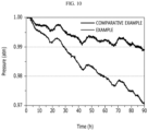
- the gas pressure inside the battery cell over time was measured, and the results are shown in FIG. 10 .
- the initial internal pressure of the battery cell was 1 atm.
- FIG. 10 is a diagram showing a measurement result of a gas pressure in a battery cell according to Experimental Example 2.
- the internal pressure decreases relatively little as time elapses in a state where the initial internal pressure is 1 atm.
- the internal pressure is relatively significantly decreased as time elapses in a state where the initial internal pressure is 1 atm. That is, in the battery cell according to the example, it may be confirmed that the internal gas is effectively discharged to the outside through the gas discharge portion formed in the lead film over time.
- the gas discharge portion is formed in the lead film, it may be confirmed that the gas is easily discharged to the outside through the gas discharge portion when the pressure inside the battery cell increases.
Landscapes
- Chemical & Material Sciences (AREA)
- Chemical Kinetics & Catalysis (AREA)
- Electrochemistry (AREA)
- General Chemical & Material Sciences (AREA)
- Sealing Battery Cases Or Jackets (AREA)
- Gas Exhaust Devices For Batteries (AREA)
- Secondary Cells (AREA)
- Battery Mounting, Suspending (AREA)
Description
- The present application claims priority to
Korean Patent Application No. 10-2020-0147669 filed on November 6, 2020 Korean Patent Application No. 10-2021-0142441 filed on October 25, 2021 - The present disclosure relates to a battery cell and a battery module including the same, and more particularly, to a battery cell with improved external emission of gas generated inside the battery cell, and a battery module including the same.
- As technology development and demand for mobile devices increase, the demand for secondary batteries as an energy source is rapidly increasing. In particular, secondary batteries are of great interest as energy sources not only for mobile devices such as mobile phones, digital cameras, notebooks and wearable devices, but also for power devices such as electric bicycles, electric vehicles and hybrid electric vehicles.
- Depending on the shape of a battery case, these secondary batteries are classified into a cylindrical battery and a prismatic battery in which a battery assembly is included in a cylindrical or prismatic metal can, and a pouch-type battery in which the battery assembly is included in a pouch-type case of an aluminum laminate sheet. Here, the battery assembly included in the battery case is a power element including a positive electrode, a negative electrode, and a separator interposed between the positive electrode and the negative electrode, and capable of charging and discharging, and is classified into a jelly-roll type in which long sheet-type positive and negative electrodes coated with an active material are wound with a separator being interposed therebetween, and a stack type in which a plurality of positive and negative electrodes are sequentially stacked with a separator being interposed therebetween.
- Among them, in particular, a pouch-type battery in which a stack-type or stack/folding-type battery assembly is included in a pouch-type battery case made of an aluminum laminate sheet is being used more and more due to low manufacturing cost, small weight, and easy deformation.
-
FIG. 1 is a top view showing a conventional battery cell.FIG. 2 is a cross-sectional view, taken along the axis a-a' ofFIG. 1 . Referring toFIGS. 1 and 2 , aconventional battery cell 10 includes abattery case 20 having anaccommodation portion 21 in which abattery assembly 11 is mounted, and asealing portion 25 formed by sealing an outer periphery thereof by heat fusion. Here, thebattery cell 10 includes anelectrode lead 30 protruding out of thebattery case 20 via thesealing portion 25, and alead film 40 is positioned between upper and lower portions of theelectrode lead 30 and thesealing portion 25. - However, as the energy density of the battery cell increases in recent years, there is a problem that the amount of gas generated inside the battery cell also increases. In the case of the
conventional battery cell 10, a component capable of discharging the gas generated inside the battery cell is not included, so a venting may occur in the battery cell due to gas generation. In addition, moisture may penetrate into the battery cell damaged by the venting, which may cause side reactions, and there is a problem that battery performance deteriorates and additional gas is generated. Accordingly, there is an increasing need to develop a battery cell with improved external emission of gas generated inside the battery cell. - In other realizations
CN 107 925 033 A concerns a battery cell with a gas discharge pipe embedded in a lead film away from an electrode lead,US 10 141 553 B2 WO 2014/109481 A1 concerns a battery cell with gas discharge portion opened towards the exterior or the case of the battery cell. - The present disclosure is designed to solve the problems of the related art, and therefore the present disclosure is directed to providing a battery cell with improved external emission of gas generated inside the battery cell, and a battery module including the same.
- The object to be solved by the present disclosure is not limited to the above-mentioned object, and the objects not mentioned here may be clearly understood by those skilled in the art from this specification and the accompanying drawings.
- In one aspect of the present disclosure, there is provided a battery cell, comprising: a battery case having an accommodation portion in which a battery assembly is mounted, and a sealing portion formed by sealing an outer periphery thereof by heat fusion; an electrode lead electrically connected to an electrode tab included in the battery assembly and protruding out of the battery case via the sealing portion; and a lead film positioned at a portion corresponding to the sealing portion in at least one of an upper portion and a lower portion of the electrode lead, wherein the lead film includes a gas discharge portion formed to extend from the inside of the battery case to the outside of the battery case, and the gas discharge portion is opened toward the inside of the battery case.
- A front surface and both side surfaces of the gas discharge portion based on a protruding direction of the electrode lead are closed.
- The battery cell may further comprise an inner layer configured to cover at least a part of a surface of the gas discharge portion.
- A material of the inner layer may have a higher melting point compared to a material of the lead film and may not react with an electrolytic solution.
- The lead film may comprise a polyolefin-based material, and the inner layer may contain at least one of polyolefin-based, fluorine-based and porous ceramic-based materials.
- The lead film may have a greater width than the electrode lead.
- The lead film may have a greater length than the sealing portion and have a smaller length than the electrode lead.
- The gas discharge portion may have a greater width than the electrode lead.
- The lead film may include a first lead film and a second lead film, the first lead film may be positioned at an upper portion of the electrode lead, and the second lead film may be positioned at a lower portion of the electrode lead.
- The electrode lead may be positioned between the first lead film and the second lead film, and the first lead film and the second lead film may be connected to each other.
- An end of the gas discharge portion formed within the lead film may be positioned outer than an outer surface of the battery case.
- An end of the gas discharge portion opened toward the inside of the battery case may be positioned inner than an inner surface of the battery case.
- In another aspect of the present disclosure, there is also provided a battery module, comprising the battery cell described above.
- According to the embodiments, since the present disclosure provides a battery cell including an electrode lead to which a lead film having a maximum penetration area is attached, and a battery module including the same, it is possible to improve the external emission of gas generated inside the battery cell.
- The effect of the present disclosure is not limited to the above effects, and the effects not mentioned here will be clearly understood by those skilled in the art from this specification and the accompanying drawings.
-
-
FIG. 1 is a top view showing a conventional battery cell. -
FIG. 2 is a cross-sectional view, taken along the axis a-a' ofFIG. 1 . -
FIG. 3 is a top view showing a battery cell according to this embodiment. -
FIG. 4 is a perspective view showing an electrode lead included in the battery cell ofFIG. 3 . -
FIG. 5 is a cross-sectional view, taken along the axis c-c' ofFIG. 4 . -
FIG. 6 is a cross-sectional view, taken along the axis d-d' ofFIG. 4 . -
FIG. 7 is a cross-sectional view, taken along the axis b-b' ofFIG. 3 . -
FIG. 8 is a diagram showing the flow of gas generated inside the battery cell ofFIG. 7 and discharged to the outside. -
FIG. 9 is a diagram showing a cross section of a battery cell according to Experimental Example 1. -
FIG. 10 is a diagram showing a measurement result of a gas pressure in a battery cell according to Experimental Example 2. - Hereinafter, with reference to the accompanying drawings, various embodiments of the present disclosure will be described in detail so as to be easily implemented by those skilled in the art. The present disclosure may be implemented in various different forms and is not limited to the embodiments described herein.
- In order to clearly explain the present disclosure, parts irrelevant to the description are omitted, and identical or similar components are endowed with the same reference signs throughout the specification.
- In addition, since the size and thickness of each component shown in the drawings are arbitrarily expressed for convenience of description, the present disclosure is not necessarily limited to the drawings. In order to clearly express various layers and regions in the drawings, the thicknesses are enlarged. Also, in the drawings, for convenience of explanation, the thickness of some layers and regions is exaggerated.
- In addition, throughout the specification, when a part "includes" a certain component, it means that other components may be further included, rather than excluding other components, unless otherwise stated.
- In addition, throughout the specification, when referring to "top view", it means that the target part is viewed from above, and when referring to "cross-sectional view", it means that a vertically-cut section of the target part is viewed from a side.
- Hereinafter, a
pouch battery cell 100 according to an embodiment of the present disclosure will be described. However, here, the description will be made based on one side surface of both side surfaces of thepouch battery cell 100, but it is not necessarily limited thereto, and the same or similar contents may be described in the case of the other side surface. -
FIG. 3 is a top view showing a battery cell according to this embodiment. - Referring to
FIG. 3 , thebattery cell 100 according to this embodiment includes abattery case 200, anelectrode lead 300, and alead film 400. - The
battery case 200 includes anaccommodation portion 210 in which abattery assembly 110 is mounted, and asealing portion 250 formed by sealing an outer periphery thereof by heat fusion. Thebattery case 200 may be a laminate sheet including a resin layer and a metal layer. More specifically, thebattery case 200 may be made of a laminate sheet, and may include an outer resin layer forming the outermost layer, a barrier metal layer preventing penetration of materials, and an inner resin layer for sealing. - Also, the
battery assembly 110 may have a structure of a jelly-roll type (winding type), a stack type (lamination type), or a composite type (stack/folding type). More specifically, thebattery assembly 110 may include a positive electrode, a negative electrode, and a separator disposed therebetween. - Hereinafter, the
electrode lead 300 and thelead film 400 will be mainly described. -
FIG. 4 is a perspective view showing an electrode lead included in the battery cell ofFIG. 3 . - Referring to
FIGS. 3 and 4 , theelectrode lead 300 is electrically connected to an electrode tab (not shown) included in thebattery assembly 110, and protrudes out of thebattery case 200 via the sealingportion 250. In addition, thelead film 400 is positioned at a portion corresponding to the sealingportion 250 in at least one of an upper portion and a lower portion of theelectrode lead 300. Accordingly, thelead film 400 may improve the sealing properties of the sealingportion 250 and theelectrode lead 300 while preventing a short circuit from occurring in theelectrode lead 300 during thermal fusion. - In addition, the
lead film 400 may have a greater width than theelectrode lead 300. The lead film may have a greater length than the sealing portion and have a smaller length than the electrode lead. Accordingly, thelead film 400 may prevent the side surface of theelectrode lead 300 from being exposed to the outside without interfering with the electrical connection of theelectrode lead 300. - In addition, the
lead film 400 may include a first lead film and a second lead film, the first lead film may be positioned at an upper portion of theelectrode lead 300, and the second lead film may be positioned at a lower portion of theelectrode lead 300. At this time, theelectrode lead 300 may be heat-fused together with the sealingportion 250 in a state of being located between the first lead film and the second lead film, so that the first lead film and the second lead film may be connected to each other. - Accordingly, the
lead film 400 may prevent the side surface of theelectrode lead 300 from being exposed to the outside, while improving the sealing properties of the sealingportion 250 and theelectrode lead 300. -
FIG. 5 is a cross-sectional view, taken along the axis c-c' ofFIG. 4 .FIG. 6 is a cross-sectional view, taken along the axis d-d' ofFIG. 4 .FIG. 7 is a cross-sectional view, taken along the axis b-b' ofFIG. 3 . - Referring to
FIGS. 5 to 7 , thelead film 400 includes agas discharge portion 450 formed to extend from the inside of thebattery case 200 to the outside of thebattery case 200, and thegas discharge portion 450 is opened toward the inside of thebattery case 200. In addition, a front surface and both side surfaces of thegas discharge portion 450 based on a protruding direction of theelectrode lead 300 are closed. Here, thegas discharge portion 450 may refer to a portion in which the remaining surfaces of thelead film 400 other than for the surface opened toward the inside of thebattery case 200 are not adhered with each other. In addition, thegas discharge portion 450 may have a greater width than theelectrode lead 300. - Accordingly, the gas generated inside the
battery case 200 flows in thegas discharge portion 450 of thelead film 400. In addition, when the pressure of thelead film 400 is higher than a predetermined pressure, the gas generated inside thebattery case 200 passes through thegas discharge portion 450 to be discharged to the outside. In addition, since a gas permeation area is maximized by thegas discharge portion 450, thelead film 400 discharges a large amount of gas. - In addition, the
lead film 400 may further include aninner layer 410 that covers at least a part of the surface of thegas discharge portion 450. More preferably, theinner layer 410 may cover the entire surface of thegas discharge portion 450. Here, theinner layer 410 may be coated on thegas discharge portion 450 or may be manufactured as a separate film and attached to thegas discharge portion 450. - Accordingly, even if the
lead film 400 is heat-fused together with the sealingportion 250 in a state of being located in at least one of the upper portion and the lower portion of theelectrode lead 300, thegas discharge portion 450 may be preserved without being heat-fused by theinner layer 410. - More specifically, the
inner layer 410 may be made of a material having a higher melting point compared to the material of thelead film 400. In addition, theinner layer 410 may be made of a material that does not react with an electrolytic solution contained in thebattery case 300. For example, thelead film 400 may include a polyolefin-based material, and theinner layer 410 may include at least one of a polyolefin-based material, a fluorine-based material, and a porous ceramic-based material. In addition, theinner layer 410 may include a getter material to increase gas permeability while minimizing water permeability. As an example, the getter material may be calcium oxide (CaO), barium oxide (BaO), lithium chloride (LiCl), silica (SiO2), or the like, but is not limited thereto, and any material reacting with water (H2O) may be used. - Accordingly, since the
inner layer 410 is made of the above-described material, theinner layer 410 does not react separately with the electrolytic solution and does not cause heat fusion, thermal deformation, or the like during the high-temperature thermal fusion process, so that thegas discharge portion 450 may be kept blank. That is, the inner surface of thegas discharge portion 450 may be maintained in a non-adhesive state. In addition, when the gas generated in thebattery case 200 flows into thegas discharge portion 450, the inner surfaces of thegas discharge portion 450 may be spaced apart from each other, so that the gas introduced into thegas discharge portion 450 may be easily discharged to the outside. In addition, since thelead film 400 is made of the above-described material, thelead film 400 may maintain the airtightness of thebattery cell 100 and also prevent leakage of the internal electrolytic solution. - Referring to
FIG. 7 , an end of thegas discharge portion 450 formed within thelead film 400 may be positioned outer than the outer surface of thebattery case 200. In addition, an end of thegas discharge portion 450 that is opened toward the inside of thebattery case 200 may be positioned inner than the inner surface of thebattery case 200. - Accordingly, the
lead film 400 may maximize the area of thegas discharge portion 450, thereby maximizing the area of theinner layer 410 to which the gas generated inside thebattery case 200 is exposed. In addition, the permeation area of the gas generated inside thebattery case 200 may be maximized, so that a large amount of gas may be discharged. -
FIG. 8 is a diagram showing the flow of gas generated inside the battery cell ofFIG. 7 and discharged to the outside. - Referring to
FIGS. 5 to 8 , the gas generated inside thebattery cell 100 ofFIG. 7 may flow toward thegas discharge portion 450 of thelead film 400. At this time, thegas discharge portion 450 may be expanded upward and downward compared toFIG. 7 by the gas inside thebattery cell 100. Also, as indicated by A inFIG. 8 , when the gas inside thebattery cell 100 exceeds a predetermined pressure, the gas inside thebattery cell 100 may be discharged to the outside through thegas discharge portion 450. - Accordingly, as compared with
FIG. 2 , as thegas discharge portion 450 is positioned on thelead film 400, the permeation area of the gas inside thebattery cell 100 is also maximized, and thus the amount of the gas discharged to the outside may also be maximized. - A battery module according to another embodiment of the present disclosure includes the battery cell described above. Meanwhile, one or more battery modules according to this embodiment may be packaged in a pack case to form a battery pack.
- The battery module described above and the battery pack including the same may be applied to various devices. These devices may be transportation means such as electric bicycles, electric vehicles, hybrid electric vehicles, and the like, but the present disclosure is not limited thereto, and the present disclosure may be applied various devices that can use a battery module and a battery pack including the same.
- Hereinafter, the content of the present disclosure will be described through more specific examples, but the following examples are for illustratively describing the present disclosure, and the scope of the present disclosure is defined by the appended claims.
- A battery cell including a battery case having an accommodation portion in which a battery assembly was mounted and a sealing portion formed by sealing an outer periphery of the battery case by heat fusion was manufactured. Here, an electrode tab included in the battery assembly was electrically connected to an electrode lead, and the electrode lead protruded out of the battery case via the sealing portion. At this time, a lead film was attached to a position corresponding to the sealing portion in an upper portion of the electrode lead, and a gas discharge portion extending from the inside of the battery case to the outside of the battery case was formed in the lead film.
- A battery cell was manufactured in the same manner as in the example, except that a separate gas discharge portion was not formed in the lead film.
- For the battery cell of the example, CT was taken centered on the sealing portion where the lead film and the electrode lead were located, and a CT image of the corresponding portion was obtained as shown in
FIG. 9 . -
FIG. 9 is a diagram showing a cross section of a battery cell according to Experimental Example 1. In the battery cell of the example,FIG. 9(a) is a CT image of a cross-section of the lead film and electrode lead before the internal pressure of the battery cell of the example is increased, andFIG. 9(b) is a CT image of a cross-section of the lead film and electrode lead after the internal pressure of the battery cell of the example increases by injecting gas into the battery cell of the example. - Referring to
FIG. 9(a) , it is confirmed that, before the internal pressure of the battery cell of the example increases, there is no significant change centered on the gas discharge portion formed on the lead film. However, as the internal pressure of the battery cell of the example increases, it may be seen that the gas discharge portion formed in the lead film is spaced apart in the vertical direction (arrow direction), as shown inFIG. 9(b) . - Accordingly, as in this example, if the gas discharge portion is formed in the lead film of the battery cell, the gas discharge portion is vertically spaced apart when the internal pressure of the battery cell increases, so that the gas inside the battery cell may be introduced into the gas discharge portion. That is, it may be seen that the gas discharge portion included in the battery cell of this example serves as a gas discharge path of the battery cell.
- For the battery cells of the example and the comparative example, the gas pressure inside the battery cell over time was measured, and the results are shown in
FIG. 10 . In the battery cell of the example, the initial internal pressure of the battery cell was 1 atm. -
FIG. 10 is a diagram showing a measurement result of a gas pressure in a battery cell according to Experimental Example 2. - Referring to
FIG. 10 , it may be confirmed that, in the battery cell according to the comparative example, the internal pressure decreases relatively little as time elapses in a state where the initial internal pressure is 1 atm. On the contrary, in the battery cell according to the example, it may be seen that the internal pressure is relatively significantly decreased as time elapses in a state where the initial internal pressure is 1 atm. That is, in the battery cell according to the example, it may be confirmed that the internal gas is effectively discharged to the outside through the gas discharge portion formed in the lead film over time. - Accordingly, in the battery cell according to the example, since the gas discharge portion is formed in the lead film, it may be confirmed that the gas is easily discharged to the outside through the gas discharge portion when the pressure inside the battery cell increases.
-
- 100: battery cell
- 110: battery assembly
- 200: battery case
- 210: accommodation portion
- 250: sealing portion
- 300: electrode lead
- 400: lead film
- 410: inner layer
- 450: gas discharge portion
Claims (12)
- A battery cell (100), comprising:a battery case (200) having an accommodation portion (210) in which a battery assembly (110) is mounted, and a sealing portion (250) formed by sealing an outer periphery thereof by heat fusion;an electrode lead (300) electrically connected to an electrode tab included in the battery assembly and protruding out of the battery case via the sealing portion (250); anda lead film (400) positioned at a portion corresponding to the sealing portion (250) in at least one of an upper portion and a lower portion of the electrode lead (300),characterised in that the lead film (400) discharges gas and includes a gas discharge portion (450) formed to extend from the inside of the battery case to the outside of the battery case, wherein the gas discharge portion (450) maximizes a gas permeation area andthe gas discharge portion (450) is opened toward the inside of the battery case and is closed on a front surface and on both side surfaces based on a protruding direction of the electrode lead (300), wherein gas generated inside the battery cell exceeding a predetermined pressure flows inside the gas discharge portion and is discharged to the outside through the gas discharge portion (450).
- The battery cell according to claim 1, further comprising:
an inner layer (410) configured to cover at least a part of a surface of the gas discharge portion (450). - The battery cell according to claim 2,
wherein a material of the inner layer (410) has a higher melting point compared to a material of the lead film (400) and does not react with an electrolytic solution. - The battery cell according to claim 3,wherein the lead film (400) contains a polyolefin-based material, andthe inner layer (410) contains at least one of polyolefin-based, fluorine-based and porous ceramic-based materials.
- The battery cell according to claim 1,
wherein the lead film (400) has a greater width than the electrode lead (300). - The battery cell according to claim 5,
wherein the lead film (400) has a greater length than the sealing portion (250) and has a smaller length than the electrode lead (300). - The battery cell according to claim 5,
wherein the gas discharge portion (450) has a greater width than the electrode lead (300). - The battery cell according to claim 1,wherein the lead film (400) includes a first lead film and a second lead film,the first lead film is positioned at an upper portion of the electrode lead (300), andthe second lead film is positioned at a lower portion of the electrode lead (300).
- The battery cell according to claim 8,
wherein the electrode lead (300) is positioned between the first lead film and the second lead film, and the first lead film and the second lead film are connected to each other. - The battery cell according to claim 1,
wherein an end of the gas discharge portion (450) formed within the lead film (400) is positioned outer than an outer surface of the battery case (200). - The battery cell according to claim 10,
wherein an end of the gas discharge portion (450) opened toward the inside of the battery case (200) is positioned inner than an inner surface of the battery case (200). - A battery module, comprising the battery cell according to any one of claim 1 to 11.
Applications Claiming Priority (3)
| Application Number | Priority Date | Filing Date | Title |
|---|---|---|---|
| KR20200147669 | 2020-11-06 | ||
| KR1020210142441A KR102616196B1 (en) | 2020-11-06 | 2021-10-25 | Battery cell and battery module including the same |
| PCT/KR2021/015737 WO2022098063A1 (en) | 2020-11-06 | 2021-11-02 | Battery cell and battery module including same |
Publications (3)
| Publication Number | Publication Date |
|---|---|
| EP4145598A1 EP4145598A1 (en) | 2023-03-08 |
| EP4145598A4 EP4145598A4 (en) | 2024-07-24 |
| EP4145598B1 true EP4145598B1 (en) | 2025-05-14 |
Family
ID=81458115
Family Applications (1)
| Application Number | Title | Priority Date | Filing Date |
|---|---|---|---|
| EP21889528.2A Active EP4145598B1 (en) | 2020-11-06 | 2021-11-02 | Battery cell and battery module including same |
Country Status (9)
| Country | Link |
|---|---|
| US (1) | US12603366B2 (en) |
| EP (1) | EP4145598B1 (en) |
| JP (2) | JP7787822B2 (en) |
| KR (1) | KR102681885B1 (en) |
| CN (1) | CN115428239B (en) |
| ES (1) | ES3031694T3 (en) |
| HU (1) | HUE071778T2 (en) |
| PL (1) | PL4145598T3 (en) |
| WO (1) | WO2022098063A1 (en) |
Families Citing this family (3)
| Publication number | Priority date | Publication date | Assignee | Title |
|---|---|---|---|---|
| CN115136396B (en) | 2021-01-11 | 2024-06-18 | 株式会社Lg新能源 | Battery cell and battery module including the same |
| KR102498916B1 (en) * | 2022-02-14 | 2023-02-09 | 주식회사 엘지에너지솔루션 | Battery cell and battery module including the same |
| EP4362195A4 (en) | 2022-06-14 | 2025-08-06 | Lg Energy Solution Ltd | BATTERY CELL, BATTERY MODULE, BATTERY PACK AND VEHICLE |
Family Cites Families (28)
| Publication number | Priority date | Publication date | Assignee | Title |
|---|---|---|---|---|
| US4532193A (en) * | 1977-11-18 | 1985-07-30 | Polaroid Corporation | Vented frame for laminar batteries and methods of making the same |
| KR0138556B1 (en) * | 1995-06-14 | 1998-06-15 | 김광호 | Water-proof case assembly of battery electronic device |
| JP4622019B2 (en) | 1999-01-20 | 2011-02-02 | パナソニック株式会社 | Flat battery |
| KR20030066895A (en) * | 2002-02-05 | 2003-08-14 | 삼성에스디아이 주식회사 | Secondary battery |
| JP4774705B2 (en) | 2004-09-17 | 2011-09-14 | 日産自動車株式会社 | Bipolar battery provided with gas releasing means, manufacturing method thereof, and assembled battery using bipolar battery. |
| KR100684724B1 (en) | 2005-04-26 | 2007-02-20 | 삼성에스디아이 주식회사 | Secondary Battery and Safety Device Used in It |
| KR101396703B1 (en) | 2008-03-05 | 2014-05-19 | 삼성에스디아이 주식회사 | Apparatus of Removing Gas and Cylinder type Secondary Battery using the same |
| KR101240753B1 (en) * | 2011-07-06 | 2013-03-11 | 삼성에스디아이 주식회사 | Secondary battery |
| EP2709191A4 (en) * | 2012-03-28 | 2015-08-19 | Optnics Prec Co Ltd | SAFETY VALVE AND ELECTROCHEMICAL ELEMENT |
| KR101370265B1 (en) * | 2012-04-17 | 2014-03-04 | 주식회사 엘지화학 | Secondary battery, Element for secondary battery applied for it and Method of manufacturing the same |
| KR101623110B1 (en) | 2012-10-18 | 2016-05-20 | 주식회사 엘지화학 | Electrode lead and secondary battery including the same |
| KR20140087773A (en) | 2012-12-31 | 2014-07-09 | 주식회사 엘지화학 | Pouch type secondary battery with enhanced stability |
| KR101547403B1 (en) | 2013-01-11 | 2015-08-25 | 주식회사 엘지화학 | Secondary battery comprising unified positive lead and negative lead and the method for preparing thereof |
| KR20140129600A (en) | 2013-04-30 | 2014-11-07 | 주식회사 엘지화학 | Secondary battery and Component for secondary battery applied for it |
| KR101666418B1 (en) * | 2013-09-24 | 2016-10-14 | 주식회사 엘지화학 | Pouch-Type Battery Cell Having Film Member for Protecting Electrode Tap-Lead Joint Portion |
| KR20150061200A (en) * | 2013-11-27 | 2015-06-04 | 삼성에스디아이 주식회사 | Secondary battery |
| KR102318043B1 (en) * | 2015-04-22 | 2021-10-28 | 에스케이이노베이션 주식회사 | Secondary battery and battery module having the same |
| KR101818630B1 (en) * | 2015-04-22 | 2018-01-15 | 주식회사 엘지화학 | Secondary battery with improved stability |
| WO2016169025A1 (en) * | 2015-04-23 | 2016-10-27 | 长园科技实业股份有限公司 | Packaging structure of flexibly packaged lithium battery |
| KR101904587B1 (en) | 2015-09-01 | 2018-10-04 | 주식회사 엘지화학 | Battery cell and method for manufacturing the same |
| KR102066013B1 (en) * | 2016-02-17 | 2020-01-14 | 주식회사 엘지화학 | Rechargeable battery |
| KR102157892B1 (en) | 2016-08-26 | 2020-09-18 | 주식회사 엘지화학 | Pouch type secondary battery |
| US10141550B2 (en) * | 2016-10-20 | 2018-11-27 | Ford Global Technologies, Llc | Pouch battery cell assembly for traction battery |
| KR102294996B1 (en) * | 2017-05-30 | 2021-08-30 | 주식회사 엘지에너지솔루션 | Lithium Secondary Battery comprising Electrode Lead using Electric-Conductive Tube |
| KR102264635B1 (en) * | 2017-11-23 | 2021-06-15 | 주식회사 엘지에너지솔루션 | The Pouch Type Secondary Battery |
| KR102361569B1 (en) * | 2018-04-23 | 2022-02-10 | 주식회사 엘지에너지솔루션 | Pouch Type Secondary Battery With Gas Venting Means |
| EP4738588A2 (en) * | 2020-03-30 | 2026-05-06 | Ningde Amperex Technology Limited | Cell and electronic device having same |
| KR102525143B1 (en) | 2020-05-18 | 2023-04-25 | 황민석 | Medical suction device |
-
2021
- 2021-11-02 JP JP2022558536A patent/JP7787822B2/en active Active
- 2021-11-02 PL PL21889528.2T patent/PL4145598T3/en unknown
- 2021-11-02 CN CN202180027420.7A patent/CN115428239B/en active Active
- 2021-11-02 EP EP21889528.2A patent/EP4145598B1/en active Active
- 2021-11-02 HU HUE21889528A patent/HUE071778T2/en unknown
- 2021-11-02 US US17/802,425 patent/US12603366B2/en active Active
- 2021-11-02 WO PCT/KR2021/015737 patent/WO2022098063A1/en not_active Ceased
- 2021-11-02 ES ES21889528T patent/ES3031694T3/en active Active
-
2023
- 2023-12-14 KR KR1020230182297A patent/KR102681885B1/en active Active
-
2024
- 2024-11-28 JP JP2024207728A patent/JP2025026485A/en active Pending
Also Published As
| Publication number | Publication date |
|---|---|
| KR20230173641A (en) | 2023-12-27 |
| EP4145598A1 (en) | 2023-03-08 |
| WO2022098063A1 (en) | 2022-05-12 |
| JP2023519377A (en) | 2023-05-10 |
| ES3031694T3 (en) | 2025-07-10 |
| CN115428239A (en) | 2022-12-02 |
| US12603366B2 (en) | 2026-04-14 |
| PL4145598T3 (en) | 2025-07-14 |
| US20230084670A1 (en) | 2023-03-16 |
| JP7787822B2 (en) | 2025-12-17 |
| EP4145598A4 (en) | 2024-07-24 |
| KR102681885B1 (en) | 2024-07-04 |
| JP2025026485A (en) | 2025-02-21 |
| CN115428239B (en) | 2025-03-11 |
| HUE071778T2 (en) | 2025-09-28 |
Similar Documents
| Publication | Publication Date | Title |
|---|---|---|
| EP4195379A1 (en) | Battery cell, manufacturing method therefor, and battery module comprising same | |
| EP4187692B1 (en) | Battery cell and battery module including the same | |
| EP4145598B1 (en) | Battery cell and battery module including same | |
| KR102616196B1 (en) | Battery cell and battery module including the same | |
| EP4170804A1 (en) | Battery cell and battery module including same | |
| EP4243177A1 (en) | Battery cell and battery module comprising same | |
| EP4178015B1 (en) | Battery cell and battery module including same | |
| EP4203149A1 (en) | Battery cell and battery module including same | |
| US12614790B2 (en) | Battery cell and battery module comprising same | |
| EP4195378B1 (en) | Battery cell and battery cell manufacturing apparatus | |
| EP4106090B1 (en) | Battery cell and battery module including the same | |
| EP4391186B1 (en) | Battery cell and battery module comprising same |
Legal Events
| Date | Code | Title | Description |
|---|---|---|---|
| STAA | Information on the status of an ep patent application or granted ep patent |
Free format text: STATUS: THE INTERNATIONAL PUBLICATION HAS BEEN MADE |
|
| PUAI | Public reference made under article 153(3) epc to a published international application that has entered the european phase |
Free format text: ORIGINAL CODE: 0009012 |
|
| STAA | Information on the status of an ep patent application or granted ep patent |
Free format text: STATUS: REQUEST FOR EXAMINATION WAS MADE |
|
| 17P | Request for examination filed |
Effective date: 20221130 |
|
| AK | Designated contracting states |
Kind code of ref document: A1 Designated state(s): AL AT BE BG CH CY CZ DE DK EE ES FI FR GB GR HR HU IE IS IT LI LT LU LV MC MK MT NL NO PL PT RO RS SE SI SK SM TR |
|
| DAV | Request for validation of the european patent (deleted) | ||
| DAX | Request for extension of the european patent (deleted) | ||
| A4 | Supplementary search report drawn up and despatched |
Effective date: 20240621 |
|
| RIC1 | Information provided on ipc code assigned before grant |
Ipc: H01M 50/557 20210101ALI20240617BHEP Ipc: H01M 50/367 20210101ALI20240617BHEP Ipc: H01M 50/193 20210101ALI20240617BHEP Ipc: H01M 50/184 20210101ALI20240617BHEP Ipc: H01M 50/178 20210101ALI20240617BHEP Ipc: H01M 50/105 20210101ALI20240617BHEP Ipc: H01M 50/116 20210101ALI20240617BHEP Ipc: H01M 50/543 20210101ALI20240617BHEP Ipc: H01M 50/30 20210101ALI20240617BHEP Ipc: H01M 50/183 20210101ALI20240617BHEP Ipc: H01M 50/172 20210101AFI20240617BHEP |
|
| STAA | Information on the status of an ep patent application or granted ep patent |
Free format text: STATUS: EXAMINATION IS IN PROGRESS |
|
| 17Q | First examination report despatched |
Effective date: 20240930 |
|
| GRAP | Despatch of communication of intention to grant a patent |
Free format text: ORIGINAL CODE: EPIDOSNIGR1 |
|
| STAA | Information on the status of an ep patent application or granted ep patent |
Free format text: STATUS: GRANT OF PATENT IS INTENDED |
|
| INTG | Intention to grant announced |
Effective date: 20250227 |
|
| GRAS | Grant fee paid |
Free format text: ORIGINAL CODE: EPIDOSNIGR3 |
|
| GRAA | (expected) grant |
Free format text: ORIGINAL CODE: 0009210 |
|
| STAA | Information on the status of an ep patent application or granted ep patent |
Free format text: STATUS: THE PATENT HAS BEEN GRANTED |
|
| P01 | Opt-out of the competence of the unified patent court (upc) registered |
Free format text: CASE NUMBER: APP_13976/2025 Effective date: 20250321 |
|
| AK | Designated contracting states |
Kind code of ref document: B1 Designated state(s): AL AT BE BG CH CY CZ DE DK EE ES FI FR GB GR HR HU IE IS IT LI LT LU LV MC MK MT NL NO PL PT RO RS SE SI SK SM TR |
|
| REG | Reference to a national code |
Ref country code: GB Ref legal event code: FG4D |
|
| REG | Reference to a national code |
Ref country code: CH Ref legal event code: EP |
|
| REG | Reference to a national code |
Ref country code: DE Ref legal event code: R096 Ref document number: 602021030937 Country of ref document: DE |
|
| REG | Reference to a national code |
Ref country code: IE Ref legal event code: FG4D |
|
| REG | Reference to a national code |
Ref country code: SE Ref legal event code: TRGR |
|
| REG | Reference to a national code |
Ref country code: ES Ref legal event code: FG2A Ref document number: 3031694 Country of ref document: ES Kind code of ref document: T3 Effective date: 20250710 |
|
| REG | Reference to a national code |
Ref country code: NL Ref legal event code: FP |
|
| REG | Reference to a national code |
Ref country code: HU Ref legal event code: AG4A Ref document number: E071778 Country of ref document: HU |
|
| PG25 | Lapsed in a contracting state [announced via postgrant information from national office to epo] |
Ref country code: FI Free format text: LAPSE BECAUSE OF FAILURE TO SUBMIT A TRANSLATION OF THE DESCRIPTION OR TO PAY THE FEE WITHIN THE PRESCRIBED TIME-LIMIT Effective date: 20250514 Ref country code: PT Free format text: LAPSE BECAUSE OF FAILURE TO SUBMIT A TRANSLATION OF THE DESCRIPTION OR TO PAY THE FEE WITHIN THE PRESCRIBED TIME-LIMIT Effective date: 20250915 |
|
| REG | Reference to a national code |
Ref country code: LT Ref legal event code: MG9D |
|
| PG25 | Lapsed in a contracting state [announced via postgrant information from national office to epo] |
Ref country code: NO Free format text: LAPSE BECAUSE OF FAILURE TO SUBMIT A TRANSLATION OF THE DESCRIPTION OR TO PAY THE FEE WITHIN THE PRESCRIBED TIME-LIMIT Effective date: 20250814 Ref country code: GR Free format text: LAPSE BECAUSE OF FAILURE TO SUBMIT A TRANSLATION OF THE DESCRIPTION OR TO PAY THE FEE WITHIN THE PRESCRIBED TIME-LIMIT Effective date: 20250815 |
|
| REG | Reference to a national code |
Ref country code: AT Ref legal event code: MK05 Ref document number: 1795618 Country of ref document: AT Kind code of ref document: T Effective date: 20250514 |
|
| PG25 | Lapsed in a contracting state [announced via postgrant information from national office to epo] |
Ref country code: BG Free format text: LAPSE BECAUSE OF FAILURE TO SUBMIT A TRANSLATION OF THE DESCRIPTION OR TO PAY THE FEE WITHIN THE PRESCRIBED TIME-LIMIT Effective date: 20250514 |
|
| PG25 | Lapsed in a contracting state [announced via postgrant information from national office to epo] |
Ref country code: HR Free format text: LAPSE BECAUSE OF FAILURE TO SUBMIT A TRANSLATION OF THE DESCRIPTION OR TO PAY THE FEE WITHIN THE PRESCRIBED TIME-LIMIT Effective date: 20250514 |
|
| PG25 | Lapsed in a contracting state [announced via postgrant information from national office to epo] |
Ref country code: AT Free format text: LAPSE BECAUSE OF FAILURE TO SUBMIT A TRANSLATION OF THE DESCRIPTION OR TO PAY THE FEE WITHIN THE PRESCRIBED TIME-LIMIT Effective date: 20250514 |
|
| PG25 | Lapsed in a contracting state [announced via postgrant information from national office to epo] |
Ref country code: RS Free format text: LAPSE BECAUSE OF FAILURE TO SUBMIT A TRANSLATION OF THE DESCRIPTION OR TO PAY THE FEE WITHIN THE PRESCRIBED TIME-LIMIT Effective date: 20250814 |
|
| PG25 | Lapsed in a contracting state [announced via postgrant information from national office to epo] |
Ref country code: IS Free format text: LAPSE BECAUSE OF FAILURE TO SUBMIT A TRANSLATION OF THE DESCRIPTION OR TO PAY THE FEE WITHIN THE PRESCRIBED TIME-LIMIT Effective date: 20250914 |
|
| PG25 | Lapsed in a contracting state [announced via postgrant information from national office to epo] |
Ref country code: LV Free format text: LAPSE BECAUSE OF FAILURE TO SUBMIT A TRANSLATION OF THE DESCRIPTION OR TO PAY THE FEE WITHIN THE PRESCRIBED TIME-LIMIT Effective date: 20250514 |
|
| PGFP | Annual fee paid to national office [announced via postgrant information from national office to epo] |
Ref country code: NL Payment date: 20251020 Year of fee payment: 5 |
|
| PGFP | Annual fee paid to national office [announced via postgrant information from national office to epo] |
Ref country code: HU Payment date: 20251127 Year of fee payment: 5 |
|
| PGFP | Annual fee paid to national office [announced via postgrant information from national office to epo] |
Ref country code: DE Payment date: 20251020 Year of fee payment: 5 |
|
| PGFP | Annual fee paid to national office [announced via postgrant information from national office to epo] |
Ref country code: GB Payment date: 20251023 Year of fee payment: 5 |
|
| PG25 | Lapsed in a contracting state [announced via postgrant information from national office to epo] |
Ref country code: SM Free format text: LAPSE BECAUSE OF FAILURE TO SUBMIT A TRANSLATION OF THE DESCRIPTION OR TO PAY THE FEE WITHIN THE PRESCRIBED TIME-LIMIT Effective date: 20250514 Ref country code: DK Free format text: LAPSE BECAUSE OF FAILURE TO SUBMIT A TRANSLATION OF THE DESCRIPTION OR TO PAY THE FEE WITHIN THE PRESCRIBED TIME-LIMIT Effective date: 20250514 |
|
| PGFP | Annual fee paid to national office [announced via postgrant information from national office to epo] |
Ref country code: IT Payment date: 20251021 Year of fee payment: 5 |
|
| PGFP | Annual fee paid to national office [announced via postgrant information from national office to epo] |
Ref country code: FR Payment date: 20251021 Year of fee payment: 5 |
|
| PGFP | Annual fee paid to national office [announced via postgrant information from national office to epo] |
Ref country code: BE Payment date: 20251020 Year of fee payment: 5 Ref country code: TR Payment date: 20251022 Year of fee payment: 5 |
|
| PGFP | Annual fee paid to national office [announced via postgrant information from national office to epo] |
Ref country code: SE Payment date: 20251021 Year of fee payment: 5 |
|
| PG25 | Lapsed in a contracting state [announced via postgrant information from national office to epo] |
Ref country code: CZ Free format text: LAPSE BECAUSE OF FAILURE TO SUBMIT A TRANSLATION OF THE DESCRIPTION OR TO PAY THE FEE WITHIN THE PRESCRIBED TIME-LIMIT Effective date: 20250514 |
|
| PGFP | Annual fee paid to national office [announced via postgrant information from national office to epo] |
Ref country code: PL Payment date: 20251020 Year of fee payment: 5 |
|
| PG25 | Lapsed in a contracting state [announced via postgrant information from national office to epo] |
Ref country code: EE Free format text: LAPSE BECAUSE OF FAILURE TO SUBMIT A TRANSLATION OF THE DESCRIPTION OR TO PAY THE FEE WITHIN THE PRESCRIBED TIME-LIMIT Effective date: 20250514 |
|
| PG25 | Lapsed in a contracting state [announced via postgrant information from national office to epo] |
Ref country code: SK Free format text: LAPSE BECAUSE OF FAILURE TO SUBMIT A TRANSLATION OF THE DESCRIPTION OR TO PAY THE FEE WITHIN THE PRESCRIBED TIME-LIMIT Effective date: 20250514 |
|
| PGFP | Annual fee paid to national office [announced via postgrant information from national office to epo] |
Ref country code: ES Payment date: 20251215 Year of fee payment: 5 |
|
| PG25 | Lapsed in a contracting state [announced via postgrant information from national office to epo] |
Ref country code: RO Free format text: LAPSE BECAUSE OF FAILURE TO SUBMIT A TRANSLATION OF THE DESCRIPTION OR TO PAY THE FEE WITHIN THE PRESCRIBED TIME-LIMIT Effective date: 20250514 |
|
| REG | Reference to a national code |
Ref country code: DE Ref legal event code: R097 Ref document number: 602021030937 Country of ref document: DE |
|
| PLBE | No opposition filed within time limit |
Free format text: ORIGINAL CODE: 0009261 |
|
| STAA | Information on the status of an ep patent application or granted ep patent |
Free format text: STATUS: NO OPPOSITION FILED WITHIN TIME LIMIT |
|
| REG | Reference to a national code |
Ref country code: CH Ref legal event code: L10 Free format text: ST27 STATUS EVENT CODE: U-0-0-L10-L00 (AS PROVIDED BY THE NATIONAL OFFICE) Effective date: 20260325 |
|
| 26N | No opposition filed |
Effective date: 20260217 |