EP4145585B1 - Electrode assembly for secondary battery including separator with notch groove and secondary battery comprising the same - Google Patents
Electrode assembly for secondary battery including separator with notch groove and secondary battery comprising the same Download PDFInfo
- Publication number
- EP4145585B1 EP4145585B1 EP22809632.7A EP22809632A EP4145585B1 EP 4145585 B1 EP4145585 B1 EP 4145585B1 EP 22809632 A EP22809632 A EP 22809632A EP 4145585 B1 EP4145585 B1 EP 4145585B1
- Authority
- EP
- European Patent Office
- Prior art keywords
- secondary battery
- electrode assembly
- electrode
- separator
- shape
- Prior art date
- Legal status (The legal status is an assumption and is not a legal conclusion. Google has not performed a legal analysis and makes no representation as to the accuracy of the status listed.)
- Active
Links
Images


Classifications
-
- H—ELECTRICITY
- H01—ELECTRIC ELEMENTS
- H01M—PROCESSES OR MEANS, e.g. BATTERIES, FOR THE DIRECT CONVERSION OF CHEMICAL ENERGY INTO ELECTRICAL ENERGY
- H01M10/00—Secondary cells; Manufacture thereof
- H01M10/04—Construction or manufacture in general
-
- H—ELECTRICITY
- H01—ELECTRIC ELEMENTS
- H01M—PROCESSES OR MEANS, e.g. BATTERIES, FOR THE DIRECT CONVERSION OF CHEMICAL ENERGY INTO ELECTRICAL ENERGY
- H01M10/00—Secondary cells; Manufacture thereof
- H01M10/04—Construction or manufacture in general
- H01M10/0413—Large-sized flat cells or batteries for motive or stationary systems with plate-like electrodes
-
- H—ELECTRICITY
- H01—ELECTRIC ELEMENTS
- H01M—PROCESSES OR MEANS, e.g. BATTERIES, FOR THE DIRECT CONVERSION OF CHEMICAL ENERGY INTO ELECTRICAL ENERGY
- H01M10/00—Secondary cells; Manufacture thereof
- H01M10/04—Construction or manufacture in general
- H01M10/0436—Small-sized flat cells or batteries for portable equipment
-
- H—ELECTRICITY
- H01—ELECTRIC ELEMENTS
- H01M—PROCESSES OR MEANS, e.g. BATTERIES, FOR THE DIRECT CONVERSION OF CHEMICAL ENERGY INTO ELECTRICAL ENERGY
- H01M10/00—Secondary cells; Manufacture thereof
- H01M10/04—Construction or manufacture in general
- H01M10/0459—Cells or batteries with folded separator between plate-like electrodes
-
- H—ELECTRICITY
- H01—ELECTRIC ELEMENTS
- H01M—PROCESSES OR MEANS, e.g. BATTERIES, FOR THE DIRECT CONVERSION OF CHEMICAL ENERGY INTO ELECTRICAL ENERGY
- H01M10/00—Secondary cells; Manufacture thereof
- H01M10/05—Accumulators with non-aqueous electrolyte
- H01M10/052—Li-accumulators
-
- H—ELECTRICITY
- H01—ELECTRIC ELEMENTS
- H01M—PROCESSES OR MEANS, e.g. BATTERIES, FOR THE DIRECT CONVERSION OF CHEMICAL ENERGY INTO ELECTRICAL ENERGY
- H01M10/00—Secondary cells; Manufacture thereof
- H01M10/05—Accumulators with non-aqueous electrolyte
- H01M10/052—Li-accumulators
- H01M10/0525—Rocking-chair batteries, i.e. batteries with lithium insertion or intercalation in both electrodes; Lithium-ion batteries
-
- H—ELECTRICITY
- H01—ELECTRIC ELEMENTS
- H01M—PROCESSES OR MEANS, e.g. BATTERIES, FOR THE DIRECT CONVERSION OF CHEMICAL ENERGY INTO ELECTRICAL ENERGY
- H01M10/00—Secondary cells; Manufacture thereof
- H01M10/05—Accumulators with non-aqueous electrolyte
- H01M10/058—Construction or manufacture
- H01M10/0583—Construction or manufacture of accumulators with folded construction elements except wound ones, i.e. folded positive or negative electrodes or separators, e.g. with "Z"-shaped electrodes or separators
-
- H—ELECTRICITY
- H01—ELECTRIC ELEMENTS
- H01M—PROCESSES OR MEANS, e.g. BATTERIES, FOR THE DIRECT CONVERSION OF CHEMICAL ENERGY INTO ELECTRICAL ENERGY
- H01M10/00—Secondary cells; Manufacture thereof
- H01M10/05—Accumulators with non-aqueous electrolyte
- H01M10/058—Construction or manufacture
- H01M10/0585—Construction or manufacture of accumulators having only flat construction elements, i.e. flat positive electrodes, flat negative electrodes and flat separators
-
- H—ELECTRICITY
- H01—ELECTRIC ELEMENTS
- H01M—PROCESSES OR MEANS, e.g. BATTERIES, FOR THE DIRECT CONVERSION OF CHEMICAL ENERGY INTO ELECTRICAL ENERGY
- H01M10/00—Secondary cells; Manufacture thereof
- H01M10/42—Methods or arrangements for servicing or maintenance of secondary cells or secondary half-cells
- H01M10/4235—Safety or regulating additives or arrangements in electrodes, separators or electrolyte
-
- H—ELECTRICITY
- H01—ELECTRIC ELEMENTS
- H01M—PROCESSES OR MEANS, e.g. BATTERIES, FOR THE DIRECT CONVERSION OF CHEMICAL ENERGY INTO ELECTRICAL ENERGY
- H01M50/00—Constructional details or processes of manufacture of the non-active parts of electrochemical cells other than fuel cells, e.g. hybrid cells
- H01M50/10—Primary casings; Jackets or wrappings
- H01M50/102—Primary casings; Jackets or wrappings characterised by their shape or physical structure
- H01M50/103—Primary casings; Jackets or wrappings characterised by their shape or physical structure prismatic or rectangular
-
- H—ELECTRICITY
- H01—ELECTRIC ELEMENTS
- H01M—PROCESSES OR MEANS, e.g. BATTERIES, FOR THE DIRECT CONVERSION OF CHEMICAL ENERGY INTO ELECTRICAL ENERGY
- H01M50/00—Constructional details or processes of manufacture of the non-active parts of electrochemical cells other than fuel cells, e.g. hybrid cells
- H01M50/40—Separators; Membranes; Diaphragms; Spacing elements inside cells
- H01M50/46—Separators, membranes or diaphragms characterised by their combination with electrodes
-
- H—ELECTRICITY
- H01—ELECTRIC ELEMENTS
- H01M—PROCESSES OR MEANS, e.g. BATTERIES, FOR THE DIRECT CONVERSION OF CHEMICAL ENERGY INTO ELECTRICAL ENERGY
- H01M50/00—Constructional details or processes of manufacture of the non-active parts of electrochemical cells other than fuel cells, e.g. hybrid cells
- H01M50/40—Separators; Membranes; Diaphragms; Spacing elements inside cells
- H01M50/463—Separators, membranes or diaphragms characterised by their shape
- H01M50/466—U-shaped, bag-shaped or folded
-
- H—ELECTRICITY
- H01—ELECTRIC ELEMENTS
- H01M—PROCESSES OR MEANS, e.g. BATTERIES, FOR THE DIRECT CONVERSION OF CHEMICAL ENERGY INTO ELECTRICAL ENERGY
- H01M50/00—Constructional details or processes of manufacture of the non-active parts of electrochemical cells other than fuel cells, e.g. hybrid cells
- H01M50/50—Current conducting connections for cells or batteries
- H01M50/531—Electrode connections inside a battery casing
- H01M50/533—Electrode connections inside a battery casing characterised by the shape of the leads or tabs
-
- H—ELECTRICITY
- H01—ELECTRIC ELEMENTS
- H01M—PROCESSES OR MEANS, e.g. BATTERIES, FOR THE DIRECT CONVERSION OF CHEMICAL ENERGY INTO ELECTRICAL ENERGY
- H01M50/00—Constructional details or processes of manufacture of the non-active parts of electrochemical cells other than fuel cells, e.g. hybrid cells
- H01M50/50—Current conducting connections for cells or batteries
- H01M50/531—Electrode connections inside a battery casing
- H01M50/54—Connection of several leads or tabs of plate-like electrode stacks, e.g. electrode pole straps or bridges
-
- Y—GENERAL TAGGING OF NEW TECHNOLOGICAL DEVELOPMENTS; GENERAL TAGGING OF CROSS-SECTIONAL TECHNOLOGIES SPANNING OVER SEVERAL SECTIONS OF THE IPC; TECHNICAL SUBJECTS COVERED BY FORMER USPC CROSS-REFERENCE ART COLLECTIONS [XRACs] AND DIGESTS
- Y02—TECHNOLOGIES OR APPLICATIONS FOR MITIGATION OR ADAPTATION AGAINST CLIMATE CHANGE
- Y02E—REDUCTION OF GREENHOUSE GAS [GHG] EMISSIONS, RELATED TO ENERGY GENERATION, TRANSMISSION OR DISTRIBUTION
- Y02E60/00—Enabling technologies; Technologies with a potential or indirect contribution to GHG emissions mitigation
- Y02E60/10—Energy storage using batteries
-
- Y—GENERAL TAGGING OF NEW TECHNOLOGICAL DEVELOPMENTS; GENERAL TAGGING OF CROSS-SECTIONAL TECHNOLOGIES SPANNING OVER SEVERAL SECTIONS OF THE IPC; TECHNICAL SUBJECTS COVERED BY FORMER USPC CROSS-REFERENCE ART COLLECTIONS [XRACs] AND DIGESTS
- Y02—TECHNOLOGIES OR APPLICATIONS FOR MITIGATION OR ADAPTATION AGAINST CLIMATE CHANGE
- Y02P—CLIMATE CHANGE MITIGATION TECHNOLOGIES IN THE PRODUCTION OR PROCESSING OF GOODS
- Y02P70/00—Climate change mitigation technologies in the production process for final industrial or consumer products
- Y02P70/50—Manufacturing or production processes characterised by the final manufactured product
Definitions
- the present disclosure relates to an electrode assembly for secondary battery including a separator with a notch groove formed therein and a secondary battery including the same
- a secondary battery is a representative example of an electrochemical device that utilizes such electrochemical energy, and the range of use thereof tends to be gradually expanding.
- JP 2010 086731 A relates to a stack type battery and battery module
- JP 2012 059363 A relates to a battery in which a positive electrode plate and a negative electrode plate are laminated via a separator
- US 2016/104872 A1 relates to a battery cell that is used in a secondary battery such as a lithium-ion battery.
- the secondary battery has a structure in which a non-aqueous electrolyte is impregnated into electrode assembly comprising a positive electrode, a negative electrode, and a porous separator.
- the electrodes such as the positive electrode and the negative electrode must be completely separated, but there is a problem that they contact each other and a short circuit occurs due to contraction of the separator, protrusion of the electrode active material, and the like.
- Such a hard short circuit occurs in the order of short circuit between electrodes, ignition and the like while deformation of the separator and the electrode occurs mainly due to the contraction of the separator occurring at a high temperature.
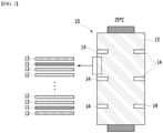
- Fig. 1 schematically shows a conventional electrode assembly
- Fig. 2 schematically shows a phenomenon in which the electrode assembly is deformed at a high temperature to occur a hard short circuit.
- a stacked body 10 includes a positive electrode 11, a negative electrode 12, and a separator 13 interposed between the positive electrode 11 and the negative electrode 12, with the separator 13 being also located at the outermost surface on both sides, and the stacked body is fixed by at least three pairs of fixing members 14 attached in the stacking direction for fixing between the separators 13 located at the outermost surface on both sides of the stacked body 10.
- contraction of the separator 13 occurs at a high temperature. Specifically, as the temperature increases, the contraction of the separator 13 is accelerated, and there is a predetermined difference depending on the material. However, the contraction in the MD/TD direction at 150°C is about 10% to 20%, and the contraction in the MD/TD direction at 180°C exceeds 40%, respectively. At this time, the contraction of the separator 13 occurs in a narrow space between the fixing members 14, whereby the positive electrode 11 is deformed together in the stacking direction as in A, and a hard short circuit between the positive electrode 11 and the negative electrode 12 occurs, which leads to ignition.
- the present disclosure has been made to solve the above-mentioned problems and other technical problems that have yet to be resolved.
- an object of the present disclosure is to provide an electrode assembly for secondary battery that can prevent hard short circuits between electrodes and improve high temperature safety by forming a notch groove in the separator of the stacked body and thus inducing a high-temperature contraction direction and path, and a secondary battery including the same.
- an electrode assembly for secondary battery comprising:
- the notch groove is formed in at least two pairs, and the notch grooves may be formed in a diagonal direction and a linear direction of each surface perpendicular to the protruding direction of the electrode tab.
- the notch groove may be formed at a position that does not interfere with the electrode tab.
- a planar shape of the notch groove may be a slit-like shape, a polygonal shape, a circular shape, or an elliptical shape.
- planar shape of the notch groove may be a slit-like shape or a triangular shape.
- the fixing member may include polyimide.
- the fixing member may be configured such that a pair of fixing members are attached at positions facing each other on both sides parallel to the protruding direction of the electrode tab, and the other at least one pair of fixing members are attached at a position facing each other on both sides parallel to the protruding direction of the electrode tab at a position spaced apart from the pair of fixing members.
- the electrode assembly may be a lamination and stack type electrode assembly or a stack and folding type electrode assembly.
- a secondary battery in which the electrode assembly according to the present disclosure is built in a secondary battery case together with an electrolyte.
- an electrode assembly for secondary battery comprising:
- Fig. 3 schematically shows an electrode assembly 100 for secondary battery according to an embodiment of the present disclosure.
- the electrode assembly 100 includes a stacked body 110 that includes a positive electrode 111, a negative electrode 112, and a separator 113 interposed between the positive electrode 111 and the negative electrode 112, and present at the outermost surface on both sides; and at least three pairs of fixing members 114 attached in the stacking direction for fixing between the separators 113 located at the outermost surface on both sides of the stacked body 110.
- the fixing member 114 is provided for fixing the stacked body 110, and may include at least two pairs of fixing members for firmly fixing the stacked body 110.
- the fixing member 114 is configured such that a pair of fixing members 114a are attached at positions facing each other on both sides parallel to the protruding direction of the electrode tabs 111a and 112a, and the other at least one pair of fixing members 114b and 114c are attached at a position facing each other on both sides parallel to the protruding direction of the electrode tabs 111a and 112a at a position spaced apart from the pair of fixing members 114a.
- various materials used for the battery can be selected, but specifically, a material that has both heat resistance and insulating property and thus does not have a short circuit problem is preferable, and for example, it may include polyimide.
- the separator 113 includes a pair of notch grooves 115 that are formed one by one on one surface perpendicular to the protruding direction of the electrode tabs 111a and 112a and the other surface located in a diagonal direction thereof, and the notch groove 115 may be formed at a position that does not interfere with the electrode tabs 111a and 112a, so as to prevent the electrode tab having a first polarity and the electrode active material layer having a second polarity from contacting with each other and causing a short circuit.
- the notch groove 114 is formed at a position where it overlaps with the electrode tabs 111a and 112b, there is a possibility that the positive electrode tab 111a and the negative electrode active material layer of the negative electrode 112 comes into contact with each other at the notch groove 115 portion to cause a short circuit. Therefore, in order to prevent these problems, the tabs 111a and 112a are formed at positions that do not interfere with each other.
- a pair of notch grooves 115 are specifically formed at horizontally and vertically symmetrical positions with respect to each other.
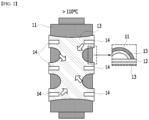
- Fig. 4 schematically shows a phenomenon in which the separator contracts and deforms when the electrode assembly 100 is exposed to a high temperature.
- a pair of notch grooves 115 are formed in the separator 113 as in the present disclosure, the separator contracts as well when the electrode assembly 100 is exposed to a high temperature.
- the pair of previously formed notch grooves 115 causes tearing of the separator in the form of connecting a pair of notch grooves 115, whereby contraction does not occur between the fixing members 114, and the positive electrode 111 and the separator 114 are not deformed in the stacking direction, thereby capable of preventing a hard short circuit, reducing the possibility of ignition and thus improving battery safety.
- the pair of notch grooves 115 causes tearing of the separator 113 while inducing a path in which the separator 113 is contracted, thereby preventing deformation of the positive electrode 111 or the negative electrode 112 in the stacking direction.
- a pair of notch grooves may be formed as shown in Figs. 3 to 4 , but at least two pairs may be formed.
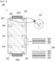
- Fig. 5 schematically shows an electrode assembly 200 in which two pairs of notch grooves are formed according to another embodiment of the present disclosure
- Fig. 6 schematically shows a phenomenon in which the separator contracts and deforms when the electrode assembly is exposed to a high temperature.
- the electrode assembly 200 includes a stacked body 210, and three pairs of fixing members 214 attached in the stacking direction for fixing between the separators 213 located at the outermost surface on both sides of the stacked body 210, similarly to those shown in Fig. 3 .
- the separator 213 includes two pairs of notch grooves 215 formed in a diagonal direction and a linear direction on each surface perpendicular to the protruding direction of the electrode tabs 211a and 212a, and the two pairs of notch grooves 215 are formed at positions that do not interfere with the electrode tabs 211a and 212a.
- the two pairs of notch grooves 215 are specifically formed in horizontally and vertically symmetrical shapes with respect to each other.
- planar shape of the notch grooves is not limited, and can be formed in various ways.
- it may be a slit-like shape, a polygonal shape, a circular shape, or an elliptical shape.
- Fig. 7 schematically shows the planar shape of the notch groove 315.
- the notch groove 315 forms the planar shape into a triangular shape, so that the contraction and tearing directions of the separator 313 can be induced in a diagonal direction ( Fig 7(a) ), or it forms the planar shape into a slit-like shape, so that the contraction and tearing direction of the separator 113 can be induced in a direction in which a slit is formed, that is, in a linear direction ( Fig.
- planar shape of the notch groove 315 may be a slit-like shape or a triangular shape so that the direction of contraction and tearing of the separator is constant and thus can minimize influence on the fixing member.
- the size of the notch groove is preferably formed into a size in which a short circuit between the positive electrode and the negative electrode does not occur due to the formation of the notch groove, that is, a size in which the positive electrode active material layer and the negative electrode active material layer are not exposed. Within this range, the size is not limited.
- the electrode assembly is not limited as long as it has a shape including a stacked body, and may be a stack type electrode assembly, a lamination and stack type electrode assembly, or a stack and folding type electrode assembly. Specifically, it may be a lamination and stack type electrode assembly or a stack and folding type electrode assembly.
- a secondary battery in which the electrode assembly is built in a secondary battery case together with an electrolyte.
- the electrolyte may be a lithium salt non-aqueous electrolyte
- the secondary battery may be a lithium secondary battery
- the electrode assembly for secondary battery forms a notch groove in the separator and gives an artificial defect to the separator, which thus induces the contraction direction and path during contraction of the separator at a high temperature, thereby exhibiting the effects of delaying and preventing hard short circuits between electrodes that may occur at high temperature, and thus, preventing ignition at high temperatures and enhancing the safety of secondary batteries.
Landscapes
- Chemical & Material Sciences (AREA)
- Chemical Kinetics & Catalysis (AREA)
- Electrochemistry (AREA)
- General Chemical & Material Sciences (AREA)
- Engineering & Computer Science (AREA)
- Manufacturing & Machinery (AREA)
- Materials Engineering (AREA)
- Secondary Cells (AREA)
- Cell Separators (AREA)
Description
- This application claims the benefit of
Korean Patent Application No. 10-2021-0067468 filed on May 26, 2021 - The present disclosure relates to an electrode assembly for secondary battery including a separator with a notch groove formed therein and a secondary battery including the same
- Due to the rapid increase in the use of fossil fuels, the demand for the use of alternative energy or clean energy is increasing, and as part thereof, the fields that are being studied most actively are the fields of power generation and power storage using electrochemistry.
- At present, a secondary battery is a representative example of an electrochemical device that utilizes such electrochemical energy, and the range of use thereof tends to be gradually expanding.
- In recent years, as mobile devices, such as portable computers, portable phones, and cameras, have been increasingly developed, the demand for secondary batteries has also sharply increased as an energy source for the mobile devices. Among such secondary batteries is a lithium secondary battery exhibiting high charge/discharge characteristics and lifetime characteristics and being environmentally friendly, in which much research has been carried out and which is now commercialized and widely used.
-
JP 2010 086731 A JP 2012 059363 A US 2016/104872 A1 relates to a battery cell that is used in a secondary battery such as a lithium-ion battery. - Generally, the secondary battery has a structure in which a non-aqueous electrolyte is impregnated into electrode assembly comprising a positive electrode, a negative electrode, and a porous separator.
- At this time, the electrodes such as the positive electrode and the negative electrode must be completely separated, but there is a problem that they contact each other and a short circuit occurs due to contraction of the separator, protrusion of the electrode active material, and the like.
- Generally, when a positive electrode active material and a negative electrode active material are short-circuited, the cell voltage drops along with small heat and the reaction is terminated. In case of a hard short circuit in which the positive electrode foil and the negative electrode active material are directly short-circuited, heat generation in mechanical, electrical or thermal abuse conditions leads to a thermal runaway, which greatly threatens safety.
- In particular, such a hard short circuit occurs in the order of short circuit between electrodes, ignition and the like while deformation of the separator and the electrode occurs mainly due to the contraction of the separator occurring at a high temperature.
-
Fig. 1 schematically shows a conventional electrode assembly, andFig. 2 schematically shows a phenomenon in which the electrode assembly is deformed at a high temperature to occur a hard short circuit. - Referring to
Figs. 1 and2 , a stackedbody 10 includes apositive electrode 11, anegative electrode 12, and aseparator 13 interposed between thepositive electrode 11 and thenegative electrode 12, with theseparator 13 being also located at the outermost surface on both sides, and the stacked body is fixed by at least three pairs offixing members 14 attached in the stacking direction for fixing between theseparators 13 located at the outermost surface on both sides of thestacked body 10. - When such a stacked
body 10 is subsequently used after being manufactured as a secondary battery, contraction of theseparator 13 occurs at a high temperature. Specifically, as the temperature increases, the contraction of theseparator 13 is accelerated, and there is a predetermined difference depending on the material. However, the contraction in the MD/TD direction at 150°C is about 10% to 20%, and the contraction in the MD/TD direction at 180°C exceeds 40%, respectively. At this time, the contraction of theseparator 13 occurs in a narrow space between thefixing members 14, whereby thepositive electrode 11 is deformed together in the stacking direction as in A, and a hard short circuit between thepositive electrode 11 and thenegative electrode 12 occurs, which leads to ignition. - Therefore, there is an urgent need to develop a technology that can solve such problems and delay or prevent hard short circuits between electrodes due to contraction of the separator at high temperatures and thus enhance safety at high temperature.
- The present disclosure has been made to solve the above-mentioned problems and other technical problems that have yet to be resolved.
- Specifically, an object of the present disclosure is to provide an electrode assembly for secondary battery that can prevent hard short circuits between electrodes and improve high temperature safety by forming a notch groove in the separator of the stacked body and thus inducing a high-temperature contraction direction and path, and a secondary battery including the same.
- According to one aspect of the present disclosure, there is provided an electrode assembly for secondary battery comprising:
- a stacked body that includes a positive electrode, a negative electrode, and a separator interposed between the positive electrode and the negative electrode, with the separator being located at the outermost surface on both sides; and
- at least two pairs of fixing members attached in the stacking direction for fixing between the separators located at the outermost surface on both sides of the stacked body,
- wherein the separator includes at least one pair of notch grooves, and
- wherein the pair of notch grooves are formed one by one on one surface perpendicular to a protruding direction of an electrode tab and the other surface located in a diagonal direction thereof.
- At this time, the notch groove is formed in at least two pairs, and the notch grooves may be formed in a diagonal direction and a linear direction of each surface perpendicular to the protruding direction of the electrode tab.
- Further, the notch groove may be formed at a position that does not interfere with the electrode tab.
- A planar shape of the notch groove may be a slit-like shape, a polygonal shape, a circular shape, or an elliptical shape.
- Meanwhile, the planar shape of the notch groove may be a slit-like shape or a triangular shape.
- The fixing member may include polyimide.
- The fixing member may be configured such that a pair of fixing members are attached at positions facing each other on both sides parallel to the protruding direction of the electrode tab, and the other at least one pair of fixing members are attached at a position facing each other on both sides parallel to the protruding direction of the electrode tab at a position spaced apart from the pair of fixing members.
- Meanwhile, the electrode assembly may be a lamination and stack type electrode assembly or a stack and folding type electrode assembly.
- According to another aspect of the present disclosure, there is provided a secondary battery in which the electrode assembly according to the present disclosure is built in a secondary battery case together with an electrolyte.
-
-
Fig. 1 schematically shows a conventional electrode assembly; -
Fig. 2 is a schematic view of a form in which a conventional electrode assembly for secondary battery is deformed at a high temperature so that the separator is contracted; -
Fig. 3 is a schematic diagram of an electrode assembly for secondary battery according to an embodiment of the present disclosure; -
Fig. 4 is a schematic view of a form in which the electrode assembly ofFig. 3 is deformed at a high temperature so that the separator is contracted; -
Fig. 5 is a schematic diagram of an electrode assembly of a secondary battery according to another embodiment of the present disclosure; -
Fig. 6 is a schematic view of a form in which the electrode assembly ofFig. 5 is deformed at a high temperature so that the separator is contracted; and -
Fig. 7 is a schematic view which shows the planar shape of the notch groove. - Hereinafter, the present disclosure will be described in more detail for a better understanding of the present disclosure.
- The technical terms provided herein is merely used for the purpose of describing particular embodiments only, and is not intended to be limiting of the present disclosure. The singular forms "a", "an", and "the" are intended to include the plural forms as well, unless the context clearly indicates otherwise.
- It should be understood that the terms "comprise", "include", "have", etc. are used herein to specify the presence of stated features, integers, steps, components or combinations thereof, but do not preclude the presence or addition of one or more other features, integers, steps, components, or combinations thereof.
- According to one embodiment of the present disclosure, there is provided an electrode assembly for secondary battery comprising:
- a stacked body that includes a positive electrode, a negative electrode, and a separator interposed between the positive electrode and the negative electrode, with the separator being located at the outermost surface on both sides; and
- at least two pairs of fixing members attached in the stacking direction for fixing between the separators located at the outermost surface on both sides of the stacked body,
- wherein the separator includes at least one pair of notch grooves, and
- wherein the pair of notch grooves are formed one by one on one surface perpendicular to a protruding direction of an electrode tab and the other surface located in a diagonal direction thereof.
-
Fig. 3 schematically shows anelectrode assembly 100 for secondary battery according to an embodiment of the present disclosure. - Referring to
Fig. 3 , theelectrode assembly 100 according to the present disclosure includes astacked body 110 that includes apositive electrode 111, anegative electrode 112, and aseparator 113 interposed between thepositive electrode 111 and thenegative electrode 112, and present at the outermost surface on both sides; and at least three pairs offixing members 114 attached in the stacking direction for fixing between theseparators 113 located at the outermost surface on both sides of thestacked body 110. - The
fixing member 114 is provided for fixing the stackedbody 110, and may include at least two pairs of fixing members for firmly fixing the stackedbody 110. - At this time, the
fixing member 114 is configured such that a pair offixing members 114a are attached at positions facing each other on both sides parallel to the protruding direction of theelectrode tabs fixing members electrode tabs fixing members 114a. - As the material constituting such a
fixing member 114, various materials used for the battery can be selected, but specifically, a material that has both heat resistance and insulating property and thus does not have a short circuit problem is preferable, and for example, it may include polyimide. - Further, according to the present disclosure, the
separator 113 includes a pair ofnotch grooves 115 that are formed one by one on one surface perpendicular to the protruding direction of theelectrode tabs notch groove 115 may be formed at a position that does not interfere with theelectrode tabs - That is, for example, when the
notch groove 114 is formed at a position where it overlaps with theelectrode tabs 111a and 112b, there is a possibility that thepositive electrode tab 111a and the negative electrode active material layer of thenegative electrode 112 comes into contact with each other at thenotch groove 115 portion to cause a short circuit. Therefore, in order to prevent these problems, thetabs - Additionally, a pair of
notch grooves 115 are specifically formed at horizontally and vertically symmetrical positions with respect to each other. -
Fig. 4 schematically shows a phenomenon in which the separator contracts and deforms when theelectrode assembly 100 is exposed to a high temperature. - Referring to
Fig. 4 , if a pair ofnotch grooves 115 are formed in theseparator 113 as in the present disclosure, the separator contracts as well when theelectrode assembly 100 is exposed to a high temperature. However, the pair of previously formednotch grooves 115 causes tearing of the separator in the form of connecting a pair ofnotch grooves 115, whereby contraction does not occur between the fixingmembers 114, and thepositive electrode 111 and theseparator 114 are not deformed in the stacking direction, thereby capable of preventing a hard short circuit, reducing the possibility of ignition and thus improving battery safety. - That is, the pair of
notch grooves 115 causes tearing of theseparator 113 while inducing a path in which theseparator 113 is contracted, thereby preventing deformation of thepositive electrode 111 or thenegative electrode 112 in the stacking direction. - Meanwhile, a pair of notch grooves may be formed as shown in
Figs. 3 to 4 , but at least two pairs may be formed. -
Fig. 5 schematically shows anelectrode assembly 200 in which two pairs of notch grooves are formed according to another embodiment of the present disclosure, andFig. 6 schematically shows a phenomenon in which the separator contracts and deforms when the electrode assembly is exposed to a high temperature. - First, referring to
Fig. 5 , theelectrode assembly 200 includes astacked body 210, and three pairs of fixingmembers 214 attached in the stacking direction for fixing between theseparators 213 located at the outermost surface on both sides of thestacked body 210, similarly to those shown inFig. 3 . However, theseparator 213 includes two pairs ofnotch grooves 215 formed in a diagonal direction and a linear direction on each surface perpendicular to the protruding direction of theelectrode tabs notch grooves 215 are formed at positions that do not interfere with theelectrode tabs notch grooves 215 are specifically formed in horizontally and vertically symmetrical shapes with respect to each other. - Referring to
Fig. 6 , when theelectrode assembly 200 in which the two pairs ofnotch grooves 215 are formed in this way is also exposed to a high temperature, theseparator 213 is contracted, and theseparator 213 is torn and contracted in a vertical direction or a diagonal direction by the two pairs ofnotch grooves 215. Therefore, similarly to theelectrode assembly 100 in which a pair of notch grooves are formed, no contraction occurs between the fixingmembers 214, and thus, the positive electrode or the negative electrode and theseparator 214 are not deformed in the stacking direction, thereby capable of preventing a hard short circuit, reducing the possibility of ignition and thus improving battery safety. - If at least two pairs of notch grooves are formed in this way, it is possible to more reliably induce the path of contraction and tearing of the separator.
- Meanwhile, the planar shape of the notch grooves is not limited, and can be formed in various ways. For example, it may be a slit-like shape, a polygonal shape, a circular shape, or an elliptical shape.
-
Fig. 7 schematically shows the planar shape of thenotch groove 315. - Referring to
Fig. 7 , thenotch groove 315 forms the planar shape into a triangular shape, so that the contraction and tearing directions of theseparator 313 can be induced in a diagonal direction (Fig 7(a) ), or it forms the planar shape into a slit-like shape, so that the contraction and tearing direction of theseparator 113 can be induced in a direction in which a slit is formed, that is, in a linear direction (Fig. 7(b) ), or it forms the planar shape into a square shape, so that the contraction and tearing direction of theseparator 113 can be induced in a direction extending from the lower corners on both sides (Fig 7(c) ), or it forms the planar shape into a circular or elliptical shape, so that the contraction and tearing direction of theseparator 313 can be induced in various directions. - However, specifically, the planar shape of the
notch groove 315 may be a slit-like shape or a triangular shape so that the direction of contraction and tearing of the separator is constant and thus can minimize influence on the fixing member. - Further, the size of the notch groove is preferably formed into a size in which a short circuit between the positive electrode and the negative electrode does not occur due to the formation of the notch groove, that is, a size in which the positive electrode active material layer and the negative electrode active material layer are not exposed. Within this range, the size is not limited.
- Meanwhile, the electrode assembly is not limited as long as it has a shape including a stacked body, and may be a stack type electrode assembly, a lamination and stack type electrode assembly, or a stack and folding type electrode assembly. Specifically, it may be a lamination and stack type electrode assembly or a stack and folding type electrode assembly.
- Since the detailed manufacturing method and configuration of such an electrode assembly are known in the art, a detailed description thereof will be omitted herein.
- Meanwhile, according to another embodiment of the present disclosure, there is provided a secondary battery in which the electrode assembly is built in a secondary battery case together with an electrolyte.
- At this time, the electrolyte may be a lithium salt non-aqueous electrolyte, and the secondary battery may be a lithium secondary battery.
- Since the above configuration is well known in the art, a detailed description thereof will be omitted herein.
- As described above, the electrode assembly for secondary battery according to an embodiment of the present disclosure forms a notch groove in the separator and gives an artificial defect to the separator, which thus induces the contraction direction and path during contraction of the separator at a high temperature, thereby exhibiting the effects of delaying and preventing hard short circuits between electrodes that may occur at high temperature, and thus, preventing ignition at high temperatures and enhancing the safety of secondary batteries.
Claims (9)
- An electrode assembly (10, 100, 200) for secondary battery comprising:a stacked body (110, 210) that includes a positive electrode (11, 111, 211), a negative electrode(12, 112, 212), and a separator (13, 113, 213, 313) interposed between the positive electrode (11, 111, 211) and the negative electrode (12, 112, 212), with the separator (13, 113, 213, 313) being located at the outermost surface on both sides; andat least two pairs of fixing members (14, 114, 214) attached in the stacking direction for fixing between the separators (13, 113, 213, 313) located at the outermost surface on both sides of the stacked body (110, 210),the separator (13, 113, 213, 313) including at least one pair of notch grooves (115, 215, 315),characterized in that the pair of notch grooves (115, 215, 315) are formed one by one on one surface perpendicular to a protruding direction of an electrode tab (111a, 112a, 211a, 212a) and the other surface located in a diagonal direction thereof.
- The electrode assembly (10, 100, 200) for secondary battery according to claim 1, wherein:
the notch groove (115, 215, 315) is formed in at least two pairs, and the notch grooves (115, 215, 315) are formed in a diagonal direction and a linear direction of each surface perpendicular to the protruding direction of the electrode tab (111a, 112a, 211a, 212a). - The electrode assembly (10, 100, 200) for secondary battery according to claim 1, wherein:
the notch groove (115, 215, 315) is formed at a position that does not interfere with the electrode tab (111a, 112a, 211a, 212a). - The electrode assembly (10, 100, 200) for secondary battery according to claim 1, wherein:
a planar shape of the notch groove (115, 215, 315) is a slit-like shape, a polygonal shape, a circular shape, or an elliptical shape. - The electrode assembly (10, 100, 200) for secondary battery according to claim 4, wherein:
the planar shape of the notch groove (115, 215, 315) is a slit-like shape or a triangular shape. - The electrode assembly (10, 100, 200) for secondary battery according to claim 1, wherein:
the fixing member (14, 114, 214) includes polyimide. - The electrode assembly (10, 100, 200) for secondary battery according to claim 1, wherein:
the fixing member (14, 114, 214) is configured such that a pair of fixing members (14, 114, 214) are attached at positions facing each other on both sides parallel to the protruding direction of the electrode tab (111a, 112a, 211a, 212a), and the other at least one pair of fixing members (14, 114, 214) are attached at a position facing each other on both sides parallel to the protruding direction of the electrode tab (111a, 112a, 211a, 212a) at a position spaced apart from the pair of fixing members. - The electrode assembly (10, 100, 200) for secondary battery according to claim 1, wherein:
the electrode assembly (10, 100, 200) is a lamination and stack type electrode assembly or a stack and folding type electrode assembly. - A secondary battery in which the electrode assembly (10, 100, 200) according to claim 1 is built in a secondary battery case together with an electrolyte.
Applications Claiming Priority (2)
| Application Number | Priority Date | Filing Date | Title |
|---|---|---|---|
| KR1020210067468A KR20220159633A (en) | 2021-05-26 | 2021-05-26 | Electrode assembly for secondary battery including seperator with notch groove and manufacturing method thereof |
| PCT/KR2022/004501 WO2022250271A1 (en) | 2021-05-26 | 2022-03-30 | Secondary battery electrode assembly comprising separation membrane having notch groove, and secondary battery comprising same |
Publications (3)
| Publication Number | Publication Date |
|---|---|
| EP4145585A1 EP4145585A1 (en) | 2023-03-08 |
| EP4145585A4 EP4145585A4 (en) | 2024-07-24 |
| EP4145585B1 true EP4145585B1 (en) | 2025-05-28 |
Family
ID=84230031
Family Applications (1)
| Application Number | Title | Priority Date | Filing Date |
|---|---|---|---|
| EP22809632.7A Active EP4145585B1 (en) | 2021-05-26 | 2022-03-30 | Electrode assembly for secondary battery including separator with notch groove and secondary battery comprising the same |
Country Status (9)
| Country | Link |
|---|---|
| US (1) | US20240213624A1 (en) |
| EP (1) | EP4145585B1 (en) |
| JP (2) | JP7612983B2 (en) |
| KR (1) | KR20220159633A (en) |
| CN (1) | CN115699402B (en) |
| ES (1) | ES3036221T3 (en) |
| HU (1) | HUE071987T2 (en) |
| PL (1) | PL4145585T3 (en) |
| WO (1) | WO2022250271A1 (en) |
Families Citing this family (1)
| Publication number | Priority date | Publication date | Assignee | Title |
|---|---|---|---|---|
| KR20220159633A (en) * | 2021-05-26 | 2022-12-05 | 주식회사 엘지에너지솔루션 | Electrode assembly for secondary battery including seperator with notch groove and manufacturing method thereof |
Family Cites Families (20)
| Publication number | Priority date | Publication date | Assignee | Title |
|---|---|---|---|---|
| US20090136834A1 (en) * | 2007-11-27 | 2009-05-28 | Qinetiq Limited | Method of Constructing an Electrode Assembly |
| JP2010086731A (en) * | 2008-09-30 | 2010-04-15 | Sanyo Electric Co Ltd | Laminated battery and battery pack |
| EP2309568B1 (en) * | 2009-09-16 | 2012-05-30 | Samsung SDI Co., Ltd. | Secondary battery and method for manufacturing the same |
| CN102884665B (en) * | 2010-04-06 | 2015-09-30 | 株式会社Lg化学 | Improved stacked battery cell or double battery cell, electrode assembly for secondary battery using same and manufacturing method thereof |
| JP5398673B2 (en) * | 2010-09-03 | 2014-01-29 | 三菱重工業株式会社 | battery |
| TW201330350A (en) * | 2011-11-01 | 2013-07-16 | Hitachi Maxell Energy Ltd | Lithium battery |
| KR101335122B1 (en) * | 2011-11-25 | 2013-12-03 | 세방전지(주) | Lithium ion battery with breakage groove |
| KR20130133639A (en) * | 2012-05-29 | 2013-12-09 | 주식회사 엘지화학 | Electrode assembly, battery cell, manufacturing mathod of electrode assembly and manufacturing mathod of battery cell |
| JP2014123699A (en) * | 2012-11-26 | 2014-07-03 | Jm Energy Corp | Electric storage device |
| KR101440008B1 (en) * | 2013-05-21 | 2014-09-12 | 니기소 가부시키가이샤 | Lamination device and lamination method |
| JPWO2015002094A1 (en) * | 2013-07-05 | 2017-02-23 | Necエナジーデバイス株式会社 | Battery cell |
| KR101620173B1 (en) * | 2013-07-10 | 2016-05-13 | 주식회사 엘지화학 | A stepwise electrode assembly with good stability and the method thereof |
| JP5858074B2 (en) * | 2014-03-13 | 2016-02-10 | 株式会社豊田自動織機 | Power storage device |
| JP6355160B2 (en) * | 2014-07-01 | 2018-07-11 | Necエナジーデバイス株式会社 | Secondary battery |
| KR102290163B1 (en) * | 2015-01-19 | 2021-08-17 | 주식회사 아모그린텍 | Flexible battery |
| JP6775154B2 (en) * | 2015-08-26 | 2020-10-28 | パナソニックIpマネジメント株式会社 | Power storage device |
| US20170092923A1 (en) * | 2015-09-29 | 2017-03-30 | Apple Inc. | Battery cells having notched electrodes |
| KR102142673B1 (en) * | 2016-03-04 | 2020-08-07 | 주식회사 엘지화학 | A electrode assembly and a pouch type cell comprising the same |
| JP2018037225A (en) * | 2016-08-30 | 2018-03-08 | 株式会社豊田自動織機 | Power storage device |
| KR20220159633A (en) * | 2021-05-26 | 2022-12-05 | 주식회사 엘지에너지솔루션 | Electrode assembly for secondary battery including seperator with notch groove and manufacturing method thereof |
-
2021
- 2021-05-26 KR KR1020210067468A patent/KR20220159633A/en active Pending
-
2022
- 2022-03-30 HU HUE22809632A patent/HUE071987T2/en unknown
- 2022-03-30 EP EP22809632.7A patent/EP4145585B1/en active Active
- 2022-03-30 US US17/928,439 patent/US20240213624A1/en active Pending
- 2022-03-30 WO PCT/KR2022/004501 patent/WO2022250271A1/en not_active Ceased
- 2022-03-30 ES ES22809632T patent/ES3036221T3/en active Active
- 2022-03-30 PL PL22809632.7T patent/PL4145585T3/en unknown
- 2022-03-30 CN CN202280004281.0A patent/CN115699402B/en active Active
- 2022-03-30 JP JP2022567424A patent/JP7612983B2/en active Active
-
2024
- 2024-09-27 JP JP2024169653A patent/JP7794273B2/en active Active
Also Published As
| Publication number | Publication date |
|---|---|
| JP7612983B2 (en) | 2025-01-15 |
| KR20220159633A (en) | 2022-12-05 |
| CN115699402A (en) | 2023-02-03 |
| JP7794273B2 (en) | 2026-01-06 |
| PL4145585T3 (en) | 2025-08-25 |
| EP4145585A1 (en) | 2023-03-08 |
| HUE071987T2 (en) | 2025-10-28 |
| JP2024178448A (en) | 2024-12-24 |
| WO2022250271A1 (en) | 2022-12-01 |
| ES3036221T3 (en) | 2025-09-16 |
| EP4145585A4 (en) | 2024-07-24 |
| CN115699402B (en) | 2025-06-17 |
| JP2023531360A (en) | 2023-07-24 |
| US20240213624A1 (en) | 2024-06-27 |
Similar Documents
| Publication | Publication Date | Title |
|---|---|---|
| US10056577B2 (en) | Battery cell of novel structure | |
| KR102152143B1 (en) | Electrode Assembly Comprising Separator Having Insulation-enhancing Part Formed on Edge Portion of Electrode | |
| CN104919637B (en) | Electrode assembly with rounded corners | |
| EP2849246A1 (en) | Battery pack having amorphous structure | |
| KR20130132231A (en) | A stepwise electrode assembly, and a battery cell, battery pack and device comprising the same | |
| KR20150098445A (en) | Battery Cell Having Electrode Coated with Insulating Material | |
| KR102886267B1 (en) | Electrode assembly including disconnection preventing layer and method for manufacturing the same | |
| EP3614477B1 (en) | Electrode assembly and battery including the same | |
| KR102108113B1 (en) | Electrode Assembly Comprising Separator Having Folded Edge | |
| KR20180067323A (en) | Battery Cell Comprising Protection Member | |
| CN111226338A (en) | Electrode assembly | |
| KR101614319B1 (en) | Battery Cell Having Separation Film of Suppressed Thermal Shrinkage | |
| KR101849990B1 (en) | Battery Cell Having Separation Film of Suppressed Thermal Shrinkage | |
| EP4145585B1 (en) | Electrode assembly for secondary battery including separator with notch groove and secondary battery comprising the same | |
| KR101730318B1 (en) | Battery Cell Having Separation Film of Suppressed Thermal Shrinkage | |
| JP2023541349A (en) | Electrode assembly with coating to prevent short circuits | |
| KR20120130557A (en) | Electrode Assembly of Improved Safety And Secondary Battery with the Same | |
| KR101746628B1 (en) | Battery Cell Providing Suppressed Exposure of Electrode and Method for Manufacturing the Same | |
| KR20060047039A (en) | Pouch type polymer secondary battery with improved safety | |
| KR100858789B1 (en) | Improved safety electrochemical cell containing damping formed by thermal fusion of separator | |
| KR20170063132A (en) | Electrode assembly and manufacturing method of electrode assembly |
Legal Events
| Date | Code | Title | Description |
|---|---|---|---|
| STAA | Information on the status of an ep patent application or granted ep patent |
Free format text: STATUS: THE INTERNATIONAL PUBLICATION HAS BEEN MADE |
|
| PUAI | Public reference made under article 153(3) epc to a published international application that has entered the european phase |
Free format text: ORIGINAL CODE: 0009012 |
|
| STAA | Information on the status of an ep patent application or granted ep patent |
Free format text: STATUS: REQUEST FOR EXAMINATION WAS MADE |
|
| 17P | Request for examination filed |
Effective date: 20221202 |
|
| AK | Designated contracting states |
Kind code of ref document: A1 Designated state(s): AL AT BE BG CH CY CZ DE DK EE ES FI FR GB GR HR HU IE IS IT LI LT LU LV MC MK MT NL NO PL PT RO RS SE SI SK SM TR |
|
| A4 | Supplementary search report drawn up and despatched |
Effective date: 20240621 |
|
| RIC1 | Information provided on ipc code assigned before grant |
Ipc: H01M 50/54 20210101ALI20240617BHEP Ipc: H01M 50/533 20210101ALI20240617BHEP Ipc: H01M 50/466 20210101ALI20240617BHEP Ipc: H01M 50/46 20210101ALI20240617BHEP Ipc: H01M 50/103 20210101ALI20240617BHEP Ipc: H01M 10/0585 20100101ALI20240617BHEP Ipc: H01M 10/0583 20100101ALI20240617BHEP Ipc: H01M 10/0525 20100101ALI20240617BHEP Ipc: H01M 10/052 20100101ALI20240617BHEP Ipc: H01M 10/04 20060101ALI20240617BHEP Ipc: H01M 50/463 20210101ALI20240617BHEP Ipc: H01M 10/42 20060101AFI20240617BHEP |
|
| DAV | Request for validation of the european patent (deleted) | ||
| DAX | Request for extension of the european patent (deleted) | ||
| GRAP | Despatch of communication of intention to grant a patent |
Free format text: ORIGINAL CODE: EPIDOSNIGR1 |
|
| STAA | Information on the status of an ep patent application or granted ep patent |
Free format text: STATUS: GRANT OF PATENT IS INTENDED |
|
| RIC1 | Information provided on ipc code assigned before grant |
Ipc: H01M 50/54 20210101ALI20250212BHEP Ipc: H01M 50/533 20210101ALI20250212BHEP Ipc: H01M 50/466 20210101ALI20250212BHEP Ipc: H01M 50/46 20210101ALI20250212BHEP Ipc: H01M 50/103 20210101ALI20250212BHEP Ipc: H01M 10/0585 20100101ALI20250212BHEP Ipc: H01M 10/0583 20100101ALI20250212BHEP Ipc: H01M 10/0525 20100101ALI20250212BHEP Ipc: H01M 10/052 20100101ALI20250212BHEP Ipc: H01M 10/04 20060101ALI20250212BHEP Ipc: H01M 50/463 20210101ALI20250212BHEP Ipc: H01M 10/42 20060101AFI20250212BHEP |
|
| INTG | Intention to grant announced |
Effective date: 20250312 |
|
| GRAS | Grant fee paid |
Free format text: ORIGINAL CODE: EPIDOSNIGR3 |
|
| GRAA | (expected) grant |
Free format text: ORIGINAL CODE: 0009210 |
|
| STAA | Information on the status of an ep patent application or granted ep patent |
Free format text: STATUS: THE PATENT HAS BEEN GRANTED |
|
| P01 | Opt-out of the competence of the unified patent court (upc) registered |
Free format text: CASE NUMBER: APP_16855/2025 Effective date: 20250407 |
|
| AK | Designated contracting states |
Kind code of ref document: B1 Designated state(s): AL AT BE BG CH CY CZ DE DK EE ES FI FR GB GR HR HU IE IS IT LI LT LU LV MC MK MT NL NO PL PT RO RS SE SI SK SM TR |
|
| REG | Reference to a national code |
Ref country code: GB Ref legal event code: FG4D |
|
| REG | Reference to a national code |
Ref country code: CH Ref legal event code: EP |
|
| REG | Reference to a national code |
Ref country code: IE Ref legal event code: FG4D Ref country code: DE Ref legal event code: R096 Ref document number: 602022015283 Country of ref document: DE |
|
| REG | Reference to a national code |
Ref country code: SE Ref legal event code: TRGR |
|
| REG | Reference to a national code |
Ref country code: ES Ref legal event code: FG2A Ref document number: 3036221 Country of ref document: ES Kind code of ref document: T3 Effective date: 20250916 |
|
| REG | Reference to a national code |
Ref country code: NL Ref legal event code: MP Effective date: 20250528 |
|
| PG25 | Lapsed in a contracting state [announced via postgrant information from national office to epo] |
Ref country code: FI Free format text: LAPSE BECAUSE OF FAILURE TO SUBMIT A TRANSLATION OF THE DESCRIPTION OR TO PAY THE FEE WITHIN THE PRESCRIBED TIME-LIMIT Effective date: 20250528 |
|
| REG | Reference to a national code |
Ref country code: LT Ref legal event code: MG9D |
|
| PG25 | Lapsed in a contracting state [announced via postgrant information from national office to epo] |
Ref country code: NO Free format text: LAPSE BECAUSE OF FAILURE TO SUBMIT A TRANSLATION OF THE DESCRIPTION OR TO PAY THE FEE WITHIN THE PRESCRIBED TIME-LIMIT Effective date: 20250828 Ref country code: GR Free format text: LAPSE BECAUSE OF FAILURE TO SUBMIT A TRANSLATION OF THE DESCRIPTION OR TO PAY THE FEE WITHIN THE PRESCRIBED TIME-LIMIT Effective date: 20250829 |
|
| PG25 | Lapsed in a contracting state [announced via postgrant information from national office to epo] |
Ref country code: NL Free format text: LAPSE BECAUSE OF FAILURE TO SUBMIT A TRANSLATION OF THE DESCRIPTION OR TO PAY THE FEE WITHIN THE PRESCRIBED TIME-LIMIT Effective date: 20250528 |
|
| PG25 | Lapsed in a contracting state [announced via postgrant information from national office to epo] |
Ref country code: BG Free format text: LAPSE BECAUSE OF FAILURE TO SUBMIT A TRANSLATION OF THE DESCRIPTION OR TO PAY THE FEE WITHIN THE PRESCRIBED TIME-LIMIT Effective date: 20250528 |
|
| PG25 | Lapsed in a contracting state [announced via postgrant information from national office to epo] |
Ref country code: HR Free format text: LAPSE BECAUSE OF FAILURE TO SUBMIT A TRANSLATION OF THE DESCRIPTION OR TO PAY THE FEE WITHIN THE PRESCRIBED TIME-LIMIT Effective date: 20250528 |
|
| PG25 | Lapsed in a contracting state [announced via postgrant information from national office to epo] |
Ref country code: RS Free format text: LAPSE BECAUSE OF FAILURE TO SUBMIT A TRANSLATION OF THE DESCRIPTION OR TO PAY THE FEE WITHIN THE PRESCRIBED TIME-LIMIT Effective date: 20250828 |
|
| PG25 | Lapsed in a contracting state [announced via postgrant information from national office to epo] |
Ref country code: IS Free format text: LAPSE BECAUSE OF FAILURE TO SUBMIT A TRANSLATION OF THE DESCRIPTION OR TO PAY THE FEE WITHIN THE PRESCRIBED TIME-LIMIT Effective date: 20250928 |
|
| REG | Reference to a national code |
Ref country code: HU Ref legal event code: AG4A Ref document number: E071987 Country of ref document: HU |
|
| PG25 | Lapsed in a contracting state [announced via postgrant information from national office to epo] |
Ref country code: LV Free format text: LAPSE BECAUSE OF FAILURE TO SUBMIT A TRANSLATION OF THE DESCRIPTION OR TO PAY THE FEE WITHIN THE PRESCRIBED TIME-LIMIT Effective date: 20250528 |
|
| REG | Reference to a national code |
Ref country code: AT Ref legal event code: MK05 Ref document number: 1799184 Country of ref document: AT Kind code of ref document: T Effective date: 20250528 |
|
| PG25 | Lapsed in a contracting state [announced via postgrant information from national office to epo] |
Ref country code: DK Free format text: LAPSE BECAUSE OF FAILURE TO SUBMIT A TRANSLATION OF THE DESCRIPTION OR TO PAY THE FEE WITHIN THE PRESCRIBED TIME-LIMIT Effective date: 20250528 Ref country code: SM Free format text: LAPSE BECAUSE OF FAILURE TO SUBMIT A TRANSLATION OF THE DESCRIPTION OR TO PAY THE FEE WITHIN THE PRESCRIBED TIME-LIMIT Effective date: 20250528 Ref country code: AT Free format text: LAPSE BECAUSE OF FAILURE TO SUBMIT A TRANSLATION OF THE DESCRIPTION OR TO PAY THE FEE WITHIN THE PRESCRIBED TIME-LIMIT Effective date: 20250528 |
|
| PG25 | Lapsed in a contracting state [announced via postgrant information from national office to epo] |
Ref country code: CZ Free format text: LAPSE BECAUSE OF FAILURE TO SUBMIT A TRANSLATION OF THE DESCRIPTION OR TO PAY THE FEE WITHIN THE PRESCRIBED TIME-LIMIT Effective date: 20250528 |
|
| PG25 | Lapsed in a contracting state [announced via postgrant information from national office to epo] |
Ref country code: EE Free format text: LAPSE BECAUSE OF FAILURE TO SUBMIT A TRANSLATION OF THE DESCRIPTION OR TO PAY THE FEE WITHIN THE PRESCRIBED TIME-LIMIT Effective date: 20250528 |
|
| PG25 | Lapsed in a contracting state [announced via postgrant information from national office to epo] |
Ref country code: SK Free format text: LAPSE BECAUSE OF FAILURE TO SUBMIT A TRANSLATION OF THE DESCRIPTION OR TO PAY THE FEE WITHIN THE PRESCRIBED TIME-LIMIT Effective date: 20250528 |
|
| PG25 | Lapsed in a contracting state [announced via postgrant information from national office to epo] |
Ref country code: IT Free format text: LAPSE BECAUSE OF FAILURE TO SUBMIT A TRANSLATION OF THE DESCRIPTION OR TO PAY THE FEE WITHIN THE PRESCRIBED TIME-LIMIT Effective date: 20250528 |
|
| REG | Reference to a national code |
Ref country code: DE Ref legal event code: R097 Ref document number: 602022015283 Country of ref document: DE |
|
| PLBE | No opposition filed within time limit |
Free format text: ORIGINAL CODE: 0009261 |
|
| STAA | Information on the status of an ep patent application or granted ep patent |
Free format text: STATUS: NO OPPOSITION FILED WITHIN TIME LIMIT |
|
| PGFP | Annual fee paid to national office [announced via postgrant information from national office to epo] |
Ref country code: SE Payment date: 20260223 Year of fee payment: 5 |
|
| PGFP | Annual fee paid to national office [announced via postgrant information from national office to epo] |
Ref country code: GB Payment date: 20260224 Year of fee payment: 5 |
|
| REG | Reference to a national code |
Ref country code: CH Ref legal event code: L10 Free format text: ST27 STATUS EVENT CODE: U-0-0-L10-L00 (AS PROVIDED BY THE NATIONAL OFFICE) Effective date: 20260409 |
|
| PGFP | Annual fee paid to national office [announced via postgrant information from national office to epo] |
Ref country code: DE Payment date: 20260220 Year of fee payment: 5 |
|
| PGFP | Annual fee paid to national office [announced via postgrant information from national office to epo] |
Ref country code: BE Payment date: 20260220 Year of fee payment: 5 |
|
| PGFP | Annual fee paid to national office [announced via postgrant information from national office to epo] |
Ref country code: HU Payment date: 20260310 Year of fee payment: 5 |
|
| PGFP | Annual fee paid to national office [announced via postgrant information from national office to epo] |
Ref country code: FR Payment date: 20260224 Year of fee payment: 5 |
|
| PGFP | Annual fee paid to national office [announced via postgrant information from national office to epo] |
Ref country code: PL Payment date: 20260223 Year of fee payment: 5 |