EP4145482A1 - Ingress-tolerant input devices comprising sliders - Google Patents
Ingress-tolerant input devices comprising sliders Download PDFInfo
- Publication number
- EP4145482A1 EP4145482A1 EP22192652.0A EP22192652A EP4145482A1 EP 4145482 A1 EP4145482 A1 EP 4145482A1 EP 22192652 A EP22192652 A EP 22192652A EP 4145482 A1 EP4145482 A1 EP 4145482A1
- Authority
- EP
- European Patent Office
- Prior art keywords
- magnet
- spring
- slider
- ingress
- electronic device
- Prior art date
- Legal status (The legal status is an assumption and is not a legal conclusion. Google has not performed a legal analysis and makes no representation as to the accuracy of the status listed.)
- Pending
Links
Images
Classifications
-
- H—ELECTRICITY
- H01—ELECTRIC ELEMENTS
- H01H—ELECTRIC SWITCHES; RELAYS; SELECTORS; EMERGENCY PROTECTIVE DEVICES
- H01H36/00—Switches actuated by change of magnetic field or of electric field, e.g. by change of relative position of magnet and switch, by shielding
- H01H36/0006—Permanent magnet actuating reed switches
- H01H36/0013—Permanent magnet actuating reed switches characterised by the co-operation between reed switch and permanent magnet; Magnetic circuits
-
- G—PHYSICS
- G01—MEASURING; TESTING
- G01D—MEASURING NOT SPECIALLY ADAPTED FOR A SPECIFIC VARIABLE; ARRANGEMENTS FOR MEASURING TWO OR MORE VARIABLES NOT COVERED IN A SINGLE OTHER SUBCLASS; TARIFF METERING APPARATUS; MEASURING OR TESTING NOT OTHERWISE PROVIDED FOR
- G01D5/00—Mechanical means for transferring the output of a sensing member; Means for converting the output of a sensing member to another variable where the form or nature of the sensing member does not constrain the means for converting; Transducers not specially adapted for a specific variable
- G01D5/12—Mechanical means for transferring the output of a sensing member; Means for converting the output of a sensing member to another variable where the form or nature of the sensing member does not constrain the means for converting; Transducers not specially adapted for a specific variable using electric or magnetic means
- G01D5/14—Mechanical means for transferring the output of a sensing member; Means for converting the output of a sensing member to another variable where the form or nature of the sensing member does not constrain the means for converting; Transducers not specially adapted for a specific variable using electric or magnetic means influencing the magnitude of a current or voltage
- G01D5/142—Mechanical means for transferring the output of a sensing member; Means for converting the output of a sensing member to another variable where the form or nature of the sensing member does not constrain the means for converting; Transducers not specially adapted for a specific variable using electric or magnetic means influencing the magnitude of a current or voltage using Hall-effect devices
- G01D5/145—Mechanical means for transferring the output of a sensing member; Means for converting the output of a sensing member to another variable where the form or nature of the sensing member does not constrain the means for converting; Transducers not specially adapted for a specific variable using electric or magnetic means influencing the magnitude of a current or voltage using Hall-effect devices influenced by the relative movement between the Hall device and magnetic fields
-
- H—ELECTRICITY
- H01—ELECTRIC ELEMENTS
- H01H—ELECTRIC SWITCHES; RELAYS; SELECTORS; EMERGENCY PROTECTIVE DEVICES
- H01H15/00—Switches having rectilinearly-movable operating part or parts adapted for actuation in opposite directions, e.g. slide switch
- H01H15/02—Details
- H01H15/06—Movable parts; Contacts mounted thereon
- H01H15/10—Operating parts
-
- H—ELECTRICITY
- H01—ELECTRIC ELEMENTS
- H01H—ELECTRIC SWITCHES; RELAYS; SELECTORS; EMERGENCY PROTECTIVE DEVICES
- H01H15/00—Switches having rectilinearly-movable operating part or parts adapted for actuation in opposite directions, e.g. slide switch
- H01H15/02—Details
- H01H15/06—Movable parts; Contacts mounted thereon
- H01H15/16—Driving mechanisms
-
- H—ELECTRICITY
- H01—ELECTRIC ELEMENTS
- H01H—ELECTRIC SWITCHES; RELAYS; SELECTORS; EMERGENCY PROTECTIVE DEVICES
- H01H9/00—Details of switching devices, not covered by groups H01H1/00 - H01H7/00
- H01H9/02—Bases, casings, or covers
- H01H9/04—Dustproof, splashproof, drip-proof, waterproof, or flameproof casings
-
- H—ELECTRICITY
- H03—ELECTRONIC CIRCUITRY
- H03K—PULSE TECHNIQUE
- H03K17/00—Electronic switching or gating, i.e. not by contact-making and –breaking
- H03K17/94—Electronic switching or gating, i.e. not by contact-making and –breaking characterised by the way in which the control signals are generated
- H03K17/965—Switches controlled by moving an element forming part of the switch
- H03K17/97—Switches controlled by moving an element forming part of the switch using a magnetic movable element
-
- H—ELECTRICITY
- H01—ELECTRIC ELEMENTS
- H01H—ELECTRIC SWITCHES; RELAYS; SELECTORS; EMERGENCY PROTECTIVE DEVICES
- H01H1/00—Contacts
- H01H1/0036—Switches making use of microelectromechanical systems [MEMS]
-
- H—ELECTRICITY
- H01—ELECTRIC ELEMENTS
- H01H—ELECTRIC SWITCHES; RELAYS; SELECTORS; EMERGENCY PROTECTIVE DEVICES
- H01H1/00—Contacts
- H01H1/50—Means for increasing contact pressure, preventing vibration of contacts, holding contacts together after engagement, or biasing contacts to the open position
-
- H—ELECTRICITY
- H01—ELECTRIC ELEMENTS
- H01H—ELECTRIC SWITCHES; RELAYS; SELECTORS; EMERGENCY PROTECTIVE DEVICES
- H01H2235/00—Springs
- H01H2235/01—Spiral spring
-
- H—ELECTRICITY
- H01—ELECTRIC ELEMENTS
- H01H—ELECTRIC SWITCHES; RELAYS; SELECTORS; EMERGENCY PROTECTIVE DEVICES
- H01H36/00—Switches actuated by change of magnetic field or of electric field, e.g. by change of relative position of magnet and switch, by shielding
- H01H36/0006—Permanent magnet actuating reed switches
Definitions
- This disclosure relates generally to input devices, and more particularly, to ingress-tolerant input devices comprising sliders.
- IP Code Ingress Protection Code
- IEC International Electrotechnical Commission
- IPX8 indicates the level of protection that mechanical casings and electrical enclosures provide against the ingress of water. More specifically, devices having the "IPX8" rating are capable of being immersed in more than 1 meter of water without harmful effects. Water ingress may be of particular concern with certain types of medical devices, such as portable medical devices that are subject to a variety of environmental conditions.
- This disclosure relates to ingress-tolerant input devices comprising sliders. Aspects of the disclosure relate to an ingress-tolerant switch assembly for operating an electronic device in an ingress-protected manner.
- the switch assembly is at least partially disposed on an outer surface of an enclosure of the electronic device and generally includes a spring, a magnet coupled to the spring, and a slider coupled to the magnet.
- a spring force of the spring is overcome by a user moving the slider relative to the enclosure such that the slider moves the magnet into proximity of the magnetic sensor to cause the magnetic sensor to generate a sensor signal for performing a function of the electronic device.
- the disclosure relates to ingress-tolerant input devices comprising sliders.
- a keypad and its electronics may be physically bonded over an opening in the housing of a portable device, and a plastic overlay material may create a watertight seal over the keypad and the device housing. Tight tolerances of mating components help ensure proper compression is maintained, but elastomers typically weaken over time, thereby decreasing compression and creating a risk of water ingress.
- an ingress-tolerant switch assembly that is operatively connected to the ingress-protected housing of an electronic device.
- the switch assembly may be ingress-tolerant in that it includes components that remain unaffected by water ingress.
- components of the switch assembly may be made of corrosion-resistant materials, such as ferromagnetic metal alloys.
- the electronic device may have a watertight housing that is free of any mechanical or electrical interfaces.
- the switch assembly is configured to communicate indirectly (e.g., electromagnetically) with the internal electronics of the electronic device.
- the switch assembly may include a slider configured to move a magnet, and the electronic device may include a magnetic sensor configured to determine the magnet's position based on electromagnetic fields passing through the electronic device housing.
- the disclosure may be described primarily with respect to electronic medical devices such as insulin delivery systems, the scope of the disclosure is not limited to electronic medical devices. Rather, the disclosure applies to and can be implemented with any suitable electronic device for which water ingress is a concern. It is intended that any aspect, embodiment, and description relating to electronic medical devices shall be applicable to any other types of electronic devices where water ingress is a concern.
- “memories” may refer to volatile and/or non-volatile memory devices, including non-transitory information storage media that may store instructions for performing operations and/or processes.
- "exemplary” does not necessarily mean “preferred” and may simply refer to an example unless the context clearly indicates otherwise.
- an exemplary ingress-protected electronic device 10 generally includes an ingress-protected enclosure 20 and a switch assembly 100 at least partially disposed on an outer surface 30 of the enclosure 20.
- the switch assembly 100 is configured to be manipulated to control functionality of the electronic device 10.
- the electronic device 10 may be, for example, a medicine delivery device configured to be secured to the body or clothing of a person for delivering a therapeutic substance (e.g., insulin) to the person.
- the switch assembly 100 may serve to effect various functionalities of the medicine delivery device such as, for example, medicine administration, adjustment of therapy settings, changing of user preferences, or the like.
- the switch assembly 100 generally includes a slider 115 (e.g., a sliding button, a sliding knob, or the like) and a switch interface 110 overlaying the recessed portion 40 from a first end 42 of the recessed portion 40 to a second end 44 of the recessed portion 40 to enclose a spring 120 and a magnet 130 within the recessed portion 40.
- a slider 115 e.g., a sliding button, a sliding knob, or the like
- switch interface 110 overlaying the recessed portion 40 from a first end 42 of the recessed portion 40 to a second end 44 of the recessed portion 40 to enclose a spring 120 and a magnet 130 within the recessed portion 40.
- the switch interface 110 may be made from a flexible material (e.g., flexible plastic, rubber, silicone, or the like) and defines a longitudinal slot 112 through which the slider 115 is configured to be moved (e.g., in response to a pushing force imparted by a person's fingertip) to communicate a command to the electronic device 10, as described in more detail below.
- a flexible material e.g., flexible plastic, rubber, silicone, or the like
- the switch interface 110 may be made from a flexible material (e.g., flexible plastic, rubber, silicone, or the like) and defines a longitudinal slot 112 through which the slider 115 is configured to be moved (e.g., in response to a pushing force imparted by a person's fingertip) to communicate a command to the electronic device 10, as described in more detail below.
- the slider 115 may be a spring-loaded sliding component of a momentary or latching switch.
- the slider 115 can stay in a first position when not pushed, move to a second position when pushed, and return to the first position when a pushing force is removed.
- the longitudinal slot 112 defined through the switch interface 110 may also serve as an egress for any fluids such as water that may have entered the recessed portion 40.
- the switch interface 110 may be positioned within the recessed portion 40 of the enclosure 20 such that an outer surface of the switch interface 110 is generally flush with an outer periphery of the enclosure 20 and the slider 115 protrudes at least partially outward from the outer periphery of the enclosure 20.
- the spring 120 may be any suitable type of spring (e.g., a coil spring, a flat spring, a leaf spring, a compression spring, or the like) and may be made from a material that is resistant to the damaging or corrosive effects of water exposure such as, for example, metal (e.g., stainless steel) or plastic.
- the spring 120 has a first end 122 coupled to the first end 42 of the recessed portion and a second end 124, opposite the first end 122, that is coupled to the magnet 130.
- the magnet 130 may be permanently or releasably coupled to the second end 124 of the spring 120 using any standard mechanical coupling interface (e.g., welding, adhesive, overmolding, latch, etc.).
- the magnet 130 may also be corrosion resistant and/or include a shell casing that is corrosion resistant.
- the magnet 130 may be a standard permanent magnet that produces its own magnetic field and has two poles, a north "N” pole and a south “S” pole, as would be understood by persons skilled in the art, and as depicted in FIG. 2 .
- a portion of the slider 115 extends through the longitudinal slot 112 and is coupled to the magnet within the recessed portion 40 such that as a user applies a pushing force to the slider 115 to move the slider 115 in the direction indicated by directional arrow "A" in FIG. 3 , the spring 120, which is situated between the magnet 130 and the first end 42 of the recessed portion 40, applies a proportional opposing force in the direction indicated by the directional arrow "B" in FIG. 3 . Movement of the slider 115 with sufficient force in the "A" direction overcomes the spring force or constant of the spring 120 to transition the spring 120 from a normal unstressed configuration ( FIG. 2 ) to a stressed configuration ( FIG. 3 ).
- the spring 120 has a first longitudinal length when in the unstressed configuration and has a second longitudinal length when in the stressed configuration that is less than the first length. Movement of the slider 115 in the "A" direction correspondingly moves the magnet 130 in the "A” direction toward the first end 42 of the recessed portion 40 against the bias of the spring 120 such that the magnet 130 moves in a direction (e.g., "A" direction) that is parallel to the direction of the pushing force applied to the slider 115.
- a direction e.g., "A" direction
- the processing circuitry 60 is configured to receive and process sensor signals from the magnetic sensor 50.
- the processing circuitry 60 may include various types of logic circuitry, including, but not limited to, microprocessors, controllers, digital signal processors (DSPs), application specific integrated circuits (ASICs), field-programmable gate arrays (FPGAs), central processing units (CPUs), graphics processing units (GPUs), programmable logic devices, memory (e.g., random access memory, volatile memory, non-volatile memory, etc.), or other discrete or integrated logic circuitry, as well as combinations of such components.
- DSPs digital signal processors
- ASICs application specific integrated circuits
- FPGAs field-programmable gate arrays
- CPUs central processing units
- GPUs graphics processing units
- programmable logic devices e.g., random access memory, volatile memory, non-volatile memory, etc.
- memory e.g., random access memory, volatile memory, non-volatile memory, etc.
- processing circuitry may generally refer to any
- the magnetic sensor 50 is arranged inside the enclosure 20 in close proximity to the first end portion 42 of the recessed portion 40 and is configured to detect a presence or an absence of the magnetic field produced by the magnet 130. In this way, the magnetic sensor 50 may serve as a proximity sensor that detects whether the magnet 130 is within a predetermined distance from the magnetic sensor 50.
- the spring 120 When the spring 120 is in its normal unstressed configuration, as shown in FIG. 2 , the magnet 130 is sufficiently distanced from the magnetic sensor 50 so that the presence of the magnet 130 is not detectable by the magnetic sensor 50. As the spring transitions from its normal unstressed configuration to its stressed configuration, as shown in FIG. 3 , the magnet 130 moves closer to the magnetic sensor 50.
- the magnetic sensor 50 detects the presence of the magnet 130 and/or magnetic field of the magnet 130 (as depicted by magnetic north pole "N” and south pole “S”), and generates a sensor signal that is received and processed by the processing circuitry 60.
- the magnetic sensor 50 may be any standard magnetic sensor that is configured to detect the magnitude of magnetism generated by a magnetic material, examples of which include, but are not limited to, a Hall Effect sensor that varies its output voltage in response to changes in magnetic flux, a MEMS magnetic field sensor, a magnetic reed switch, or the like.
- a Hall Effect sensor that varies its output voltage in response to changes in magnetic flux
- MEMS magnetic field sensor that varies its output voltage in response to changes in magnetic flux
- a magnetic reed switch or the like.
- the sensors described above are exemplary. Other sensors or types of sensors for detecting magnetic properties, among other things, will be recognized by persons skilled in the art and are contemplated to be within the scope of the disclosure.
- the signal provided by a sensor shall be referred to as a "sensor signal.”
- the magnetic sensor 50 when the slider 115 is moved in the "A" direction the magnet 130 is urged to move in the "A" direction toward the first end 42 of the recessed portion 40 into proximity of the magnetic sensor 50, as shown in FIG. 3 .
- movement of the magnet 130 in the "A” direction is caused by transition of the spring 120 from its normal unstressed configuration ( FIG. 2 ) to its stressed configuration ( FIG. 3 ).
- the Hall Effect voltage in the magnetic sensor 50 changes due to the approaching proximity of the magnetic field of the magnet 130.
- the magnetic sensor 50 may be configured such that the magnet 130 and/or the north "N” or south “S” poles of the magnet 130 must be generally aligned with the magnetic sensor 50 or aligned (e.g., an axis of the poles "N” and “S” of the magnet 130 are parallel and substantially co-linear with a sensing axis "Y" of the magnetic sensor 50) with at least a portion of the magnetic sensor 50 before the magnetic sensor 50 communicates a sensor signal to the processing circuitry 60.
- the magnetic sensor 50 may avoid inadvertently generating multiple sensor signals and/or erroneous sensor signals caused by, for example, less than complete actuation of the slider 115, weak detection of the presence of the magnet 130, slow movement of the magnet 130 toward or away from the magnetic sensor 50, etc.
- the Hall Effect voltage changes back to its original state.
- this change in Hall Effect voltage may be communicated as a sensor signal to the processing circuitry 60 to effect performance or termination of performance of a function related to the operation of the electronic device 10.
- movement of the magnet 130 in the "B” direction is caused by the restoring force of the spring 120 transitioning the spring 120 from its stressed configuration ( FIG. 3 ) back to its normal unstressed configuration ( FIG. 2 ) when a pushing force on the slider 115 is removed ( FIG. 4 ).
- the thickness of the walls of the enclosure 20 may be made thinner or thicker to affect the sensitivity of the magnetic sensor 50 with respect to the magnet 130.
- the magnetic sensor 50 may be disposed on a printed circuit board (not shown) that is in communication with the processing circuitry 60 and secured to an inner surface of the enclosure 20 in proximity to the recessed portion 40.
- the north “N” and south “S” poles of the magnet 130 move along an axis that is parallel to the surface of the magnetic sensor 50 that faces the recessed portion 40, as shown in FIGS. 2-4 .
- the magnetic sensor 50 may be disposed in proximity to the first end portion 42 of the recessed portion 40 such that the north "N” and south “S” poles of the magnet 130 move along an axis that is perpendicular to the surface of the magnetic sensor 50 that faces the magnet 130.
- the magnetic sensor 50 may be disposed along a side wall of the recessed portion 40 instead of along the bottom wall as depicted in FIGS. 2-4 , and the north "N" and south “S” poles of the magnet 130 may run parallel to the axis of movement of the spring 120.
- a phrase in the form “A or B” means “(A), (B), or (A and B).
- a phrase in the form “at least one of A, B, or C” means "(A); (B); (C); (A and B); (A and C); (B and C); or (A, B, and C).
Landscapes
- Physics & Mathematics (AREA)
- General Physics & Mathematics (AREA)
- Switches That Are Operated By Magnetic Or Electric Fields (AREA)
Abstract
Description
- This disclosure relates generally to input devices, and more particularly, to ingress-tolerant input devices comprising sliders.
- Many electronic devices include a watertight housing or enclosure to protect the internal mechanisms and electronics from the damaging effects of water. The Ingress Protection Code (IP Code) is published by the International Electrotechnical Commission (IEC) to classify and rate the degree of protection provided by mechanical casings and electrical enclosures against intrusion, dust, accidental contact, and water. For example, the "8" in "IPX8" indicates the level of protection that mechanical casings and electrical enclosures provide against the ingress of water. More specifically, devices having the "IPX8" rating are capable of being immersed in more than 1 meter of water without harmful effects. Water ingress may be of particular concern with certain types of medical devices, such as portable medical devices that are subject to a variety of environmental conditions.
- This disclosure relates to ingress-tolerant input devices comprising sliders. Aspects of the disclosure relate to an ingress-tolerant switch assembly for operating an electronic device in an ingress-protected manner. The switch assembly is at least partially disposed on an outer surface of an enclosure of the electronic device and generally includes a spring, a magnet coupled to the spring, and a slider coupled to the magnet. A spring force of the spring is overcome by a user moving the slider relative to the enclosure such that the slider moves the magnet into proximity of the magnetic sensor to cause the magnetic sensor to generate a sensor signal for performing a function of the electronic device.
- The above and other aspects and features of the disclosure will become more apparent in view of the following detailed description when taken in conjunction with the accompanying drawings wherein like reference numerals identify similar or identical elements.
-
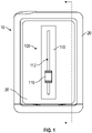
FIG. 1 is a diagram of an exemplary ingress-protected electronic device having an ingress-tolerant switch assembly, in accordance with aspects of the disclosure; -
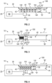
FIG. 2 is a cross-sectional view of the electronic device ofFIG. 1 illustrating components of the electronic device and showing the switch assembly in a first configuration, in accordance with aspects of the disclosure; -
FIG. 3 is a cross-sectional view of the electronic device ofFIG. 1 illustrating the switch assembly in a second configuration, in accordance with aspects of the disclosure; and -
FIG. 4 is a cross-sectional view of the electronic device ofFIG. 1 illustrating the switch assembly returning from the second configuration to the first configuration, in accordance with aspects of the disclosure. - The disclosure relates to ingress-tolerant input devices comprising sliders.
- It is desirable for portable electronic devices to have protection against the ingress of harmful elements, particularly water. However, the various moving parts involved in user input devices (e.g., buttons or switches) can pose challenges for ingress protection. For example, a keypad and its electronics may be physically bonded over an opening in the housing of a portable device, and a plastic overlay material may create a watertight seal over the keypad and the device housing. Tight tolerances of mating components help ensure proper compression is maintained, but elastomers typically weaken over time, thereby decreasing compression and creating a risk of water ingress.
- To avoid the aforementioned shortcomings, disclosed herein is an ingress-tolerant switch assembly that is operatively connected to the ingress-protected housing of an electronic device. The switch assembly may be ingress-tolerant in that it includes components that remain unaffected by water ingress. For example, components of the switch assembly may be made of corrosion-resistant materials, such as ferromagnetic metal alloys. In contrast, the electronic device may have a watertight housing that is free of any mechanical or electrical interfaces. Thus, the switch assembly is configured to communicate indirectly (e.g., electromagnetically) with the internal electronics of the electronic device. For example, the switch assembly may include a slider configured to move a magnet, and the electronic device may include a magnetic sensor configured to determine the magnet's position based on electromagnetic fields passing through the electronic device housing.
- Although the disclosure may be described primarily with respect to electronic medical devices such as insulin delivery systems, the scope of the disclosure is not limited to electronic medical devices. Rather, the disclosure applies to and can be implemented with any suitable electronic device for which water ingress is a concern. It is intended that any aspect, embodiment, and description relating to electronic medical devices shall be applicable to any other types of electronic devices where water ingress is a concern.
- Although the disclosure is not limited in this regard, discussions utilizing terms such as, for example, "processing," "computing," "calculating," "determining," "establishing," "analyzing," "checking," or the like, may refer to operation(s) and/or process(es) of a computer, a computing platform, a computing system, or other electronic computing device, that manipulates and/or transforms data represented as physical (e.g., electronic) quantities within the device's registers and/or memories into other data similarly represented as physical quantities within the device's registers and/or memories. As used herein, "memories" may refer to volatile and/or non-volatile memory devices, including non-transitory information storage media that may store instructions for performing operations and/or processes. As used herein, "exemplary" does not necessarily mean "preferred" and may simply refer to an example unless the context clearly indicates otherwise.
- Referring to
FIG. 1 , an exemplary ingress-protectedelectronic device 10 generally includes an ingress-protectedenclosure 20 and aswitch assembly 100 at least partially disposed on anouter surface 30 of theenclosure 20. Theswitch assembly 100 is configured to be manipulated to control functionality of theelectronic device 10. Theelectronic device 10 may be, for example, a medicine delivery device configured to be secured to the body or clothing of a person for delivering a therapeutic substance (e.g., insulin) to the person. In this example, theswitch assembly 100 may serve to effect various functionalities of the medicine delivery device such as, for example, medicine administration, adjustment of therapy settings, changing of user preferences, or the like. - Referring to
FIG. 2 , a cross-sectional view of theelectronic device 10 is shown and illustrates theswitch assembly 100 disposed within a recessedportion 40 defined by theouter surface 30 of theenclosure 20. Theswitch assembly 100 generally includes a slider 115 (e.g., a sliding button, a sliding knob, or the like) and aswitch interface 110 overlaying therecessed portion 40 from afirst end 42 of therecessed portion 40 to asecond end 44 of the recessedportion 40 to enclose aspring 120 and amagnet 130 within the recessedportion 40. Theswitch interface 110 may be made from a flexible material (e.g., flexible plastic, rubber, silicone, or the like) and defines alongitudinal slot 112 through which theslider 115 is configured to be moved (e.g., in response to a pushing force imparted by a person's fingertip) to communicate a command to theelectronic device 10, as described in more detail below. - In some embodiments, the
slider 115 may be a spring-loaded sliding component of a momentary or latching switch. Theslider 115 can stay in a first position when not pushed, move to a second position when pushed, and return to the first position when a pushing force is removed. In embodiments, thelongitudinal slot 112 defined through theswitch interface 110 may also serve as an egress for any fluids such as water that may have entered therecessed portion 40. - As illustrated in
FIG. 2 , theswitch interface 110 may be positioned within therecessed portion 40 of theenclosure 20 such that an outer surface of theswitch interface 110 is generally flush with an outer periphery of theenclosure 20 and theslider 115 protrudes at least partially outward from the outer periphery of theenclosure 20. Thespring 120 may be any suitable type of spring (e.g., a coil spring, a flat spring, a leaf spring, a compression spring, or the like) and may be made from a material that is resistant to the damaging or corrosive effects of water exposure such as, for example, metal (e.g., stainless steel) or plastic. Thespring 120 has afirst end 122 coupled to thefirst end 42 of the recessed portion and asecond end 124, opposite thefirst end 122, that is coupled to themagnet 130. - The
magnet 130 may be permanently or releasably coupled to thesecond end 124 of thespring 120 using any standard mechanical coupling interface (e.g., welding, adhesive, overmolding, latch, etc.). Themagnet 130 may also be corrosion resistant and/or include a shell casing that is corrosion resistant. Themagnet 130 may be a standard permanent magnet that produces its own magnetic field and has two poles, a north "N" pole and a south "S" pole, as would be understood by persons skilled in the art, and as depicted inFIG. 2 . - A portion of the
slider 115 extends through thelongitudinal slot 112 and is coupled to the magnet within therecessed portion 40 such that as a user applies a pushing force to theslider 115 to move theslider 115 in the direction indicated by directional arrow "A" inFIG. 3 , thespring 120, which is situated between themagnet 130 and thefirst end 42 of therecessed portion 40, applies a proportional opposing force in the direction indicated by the directional arrow "B" inFIG. 3 . Movement of theslider 115 with sufficient force in the "A" direction overcomes the spring force or constant of thespring 120 to transition thespring 120 from a normal unstressed configuration (FIG. 2 ) to a stressed configuration (FIG. 3 ). In embodiments, thespring 120 has a first longitudinal length when in the unstressed configuration and has a second longitudinal length when in the stressed configuration that is less than the first length. Movement of theslider 115 in the "A" direction correspondingly moves themagnet 130 in the "A" direction toward thefirst end 42 of therecessed portion 40 against the bias of thespring 120 such that themagnet 130 moves in a direction (e.g., "A" direction) that is parallel to the direction of the pushing force applied to theslider 115. With reference toFIG. 4 , when theslider 115 is no longer pushed (e.g., a pushing force on theslider 115 is removed), the restoring force of thespring 120 returns thespring 120 to its normal unstressed configuration, thereby urging theslider 115 in the "B" direction, which also urges themagnet 130 in the "B" direction, and back to a home position. - Disposed within the
enclosure 20 of theelectronic device 10 are amagnetic sensor 50 andprocessing circuitry 60 in communication with themagnetic sensor 50. Theprocessing circuitry 60 is configured to receive and process sensor signals from themagnetic sensor 50. Theprocessing circuitry 60 may include various types of logic circuitry, including, but not limited to, microprocessors, controllers, digital signal processors (DSPs), application specific integrated circuits (ASICs), field-programmable gate arrays (FPGAs), central processing units (CPUs), graphics processing units (GPUs), programmable logic devices, memory (e.g., random access memory, volatile memory, non-volatile memory, etc.), or other discrete or integrated logic circuitry, as well as combinations of such components. The term "processing circuitry" may generally refer to any of the foregoing logic circuitry, alone or in combination with other logic circuitry, or any other circuitry for performing computations. - The
magnetic sensor 50 is arranged inside theenclosure 20 in close proximity to thefirst end portion 42 of therecessed portion 40 and is configured to detect a presence or an absence of the magnetic field produced by themagnet 130. In this way, themagnetic sensor 50 may serve as a proximity sensor that detects whether themagnet 130 is within a predetermined distance from themagnetic sensor 50. When thespring 120 is in its normal unstressed configuration, as shown inFIG. 2 , themagnet 130 is sufficiently distanced from themagnetic sensor 50 so that the presence of themagnet 130 is not detectable by themagnetic sensor 50. As the spring transitions from its normal unstressed configuration to its stressed configuration, as shown inFIG. 3 , themagnet 130 moves closer to themagnetic sensor 50. When themagnet 130 is moved to within a sufficient proximity to the magnetic sensor 50 (e.g., within a predetermined distance), themagnetic sensor 50 detects the presence of themagnet 130 and/or magnetic field of the magnet 130 (as depicted by magnetic north pole "N" and south pole "S"), and generates a sensor signal that is received and processed by theprocessing circuitry 60. - In embodiments, the
magnetic sensor 50 may be any standard magnetic sensor that is configured to detect the magnitude of magnetism generated by a magnetic material, examples of which include, but are not limited to, a Hall Effect sensor that varies its output voltage in response to changes in magnetic flux, a MEMS magnetic field sensor, a magnetic reed switch, or the like. The sensors described above are exemplary. Other sensors or types of sensors for detecting magnetic properties, among other things, will be recognized by persons skilled in the art and are contemplated to be within the scope of the disclosure. For any sensor, the signal provided by a sensor shall be referred to as a "sensor signal." - In an example implementing the
magnetic sensor 50 as a Hall Effect sensor, when theslider 115 is moved in the "A" direction themagnet 130 is urged to move in the "A" direction toward thefirst end 42 of the recessedportion 40 into proximity of themagnetic sensor 50, as shown inFIG. 3 . As described above, movement of themagnet 130 in the "A" direction is caused by transition of thespring 120 from its normal unstressed configuration (FIG. 2 ) to its stressed configuration (FIG. 3 ). As themagnet 130 moves closer to themagnetic sensor 50, the Hall Effect voltage in themagnetic sensor 50 changes due to the approaching proximity of the magnetic field of themagnet 130. This change in Hall Effect voltage is communicated as a sensor signal to theprocessing circuitry 60, which effects performance or termination of performance of a function related to the operation of theelectronic device 10. In some embodiments, themagnetic sensor 50 may be configured such that themagnet 130 and/or the north "N" or south "S" poles of themagnet 130 must be generally aligned with themagnetic sensor 50 or aligned (e.g., an axis of the poles "N" and "S" of themagnet 130 are parallel and substantially co-linear with a sensing axis "Y" of the magnetic sensor 50) with at least a portion of themagnetic sensor 50 before themagnetic sensor 50 communicates a sensor signal to theprocessing circuitry 60. In this manner, themagnetic sensor 50 may avoid inadvertently generating multiple sensor signals and/or erroneous sensor signals caused by, for example, less than complete actuation of theslider 115, weak detection of the presence of themagnet 130, slow movement of themagnet 130 toward or away from themagnetic sensor 50, etc. - When the
magnet 130 moves in the "B" direction away from the magnetic sensor 50 (and the axis of the poles "N" and "S" of themagnet 130 are moved out of alignment or colinearity with the sensing axis "Y" of the magnetic sensor 50), the Hall Effect voltage changes back to its original state. In some embodiments, this change in Hall Effect voltage may be communicated as a sensor signal to theprocessing circuitry 60 to effect performance or termination of performance of a function related to the operation of theelectronic device 10. As described above, movement of themagnet 130 in the "B" direction is caused by the restoring force of thespring 120 transitioning thespring 120 from its stressed configuration (FIG. 3 ) back to its normal unstressed configuration (FIG. 2 ) when a pushing force on theslider 115 is removed (FIG. 4 ). - Depending on the type of magnetic sensor implemented, the thickness of the walls of the
enclosure 20 may be made thinner or thicker to affect the sensitivity of themagnetic sensor 50 with respect to themagnet 130. In some embodiments, themagnetic sensor 50 may be disposed on a printed circuit board (not shown) that is in communication with theprocessing circuitry 60 and secured to an inner surface of theenclosure 20 in proximity to the recessedportion 40. - In some embodiments, the north "N" and south "S" poles of the
magnet 130 move along an axis that is parallel to the surface of themagnetic sensor 50 that faces the recessedportion 40, as shown inFIGS. 2-4 . In some embodiments, themagnetic sensor 50 may be disposed in proximity to thefirst end portion 42 of the recessedportion 40 such that the north "N" and south "S" poles of themagnet 130 move along an axis that is perpendicular to the surface of themagnetic sensor 50 that faces themagnet 130. Stated differently, themagnetic sensor 50 may be disposed along a side wall of the recessedportion 40 instead of along the bottom wall as depicted inFIGS. 2-4 , and the north "N" and south "S" poles of themagnet 130 may run parallel to the axis of movement of thespring 120. - The embodiments disclosed herein are examples of the claimed subject matter, which may be embodied in various forms. For instance, although certain embodiments herein are separately described, it should be appreciated that each of the embodiments herein may be combined with one or more of the other embodiments described herein. Specific structural and functional details disclosed herein are not to be interpreted as limiting, but as a basis for the claims and as a representative basis for teaching one skilled in the art to variously employ the disclosure in virtually any appropriately detailed structure. Like reference numerals may refer to similar or identical elements throughout the description of the figures.
- The phrases "in an embodiment," "in embodiments," "in various embodiments," "in some embodiments," or "in other embodiments" may each refer to one or more of the same or different embodiments in accordance with the disclosure. A phrase in the form "A or B" means "(A), (B), or (A and B)." A phrase in the form "at least one of A, B, or C" means "(A); (B); (C); (A and B); (A and C); (B and C); or (A, B, and C)."
- It should be understood that the foregoing description is only illustrative of the disclosure. To the extent consistent, any or all of the aspects detailed herein may be used in conjunction with any or all of the other aspects detailed herein. Various alternatives and modifications can be devised by those skilled in the art without departing from the disclosure. Accordingly, the disclosure is intended to embrace all such alternatives, modifications, and variances. The embodiments described with reference to the attached drawing figures are presented only to demonstrate certain examples of the disclosure. Other elements, steps, methods, and techniques that are insubstantially different from those described above and/or in the appended claims are also intended to be within the scope of the disclosure.
- While several embodiments of the disclosure have been shown in the drawings, it is not intended that the disclosure be limited thereto, as it is intended that the disclosure be as broad in scope as the art will allow and that the specification be read likewise. Therefore, the above description should not be construed as limiting, but merely as exemplifications of particular embodiments. Those skilled in the art will envision other modifications within the scope and spirit of the claims appended hereto.
- Further disclosed herein is the subject-matter of the following clauses:
- 1. An ingress-tolerant switch assembly for operating an electronic device in an ingress-protected manner, the switch assembly comprising:
- a slider configured to move relative to an ingress-protected enclosure of an electronic device between a first position and a second position;
- a magnet coupled to the slider such that movement of the slider causes corresponding movement of the magnet relative to a magnetic sensor disposed within the enclosure; and
- a spring having a first end coupled to the enclosure and an opposite second end coupled to the magnet, the spring configured to transition between an unstressed configuration and a stressed configuration in response to movement of the slider,
- wherein movement of the slider by a user toward the second position overcomes a spring force of the spring to transition the spring from the unstressed configuration to the stressed configuration to move the magnet into proximity of the magnetic sensor to cause the magnetic sensor to generate a sensor signal for performing a function of the electronic device.
- 2. The switch assembly according to clause 1, wherein the magnetic sensor is a Hall Effect sensor or a magnetic reed switch.
- 3. The switch assembly according to clause 1 or any of the preceding clauses, wherein the magnet includes a north pole and a south pole, and the magnetic sensor is configured to generate the sensor signal in response to the north pole or the south pole of the magnet being aligned with at least a portion of the magnetic sensor.
- 4. The switch assembly according to clause 1 or any of the preceding clauses, wherein the electronic device is a medicine delivery device.
- 5. The switch assembly according to clause 1 or any of the preceding clauses, wherein movement of the slider in a first direction toward the second position causes the spring to apply a force on the magnet in a second direction opposite the first direction.
- 6. The switch assembly according to clause 1 or any of the preceding clauses, wherein the spring is formed of a corrosion resistant material.
- 7. The switch assembly according to clause 1 or any of the preceding clauses, wherein the slider is formed of an elastic material selected from the group consisting of silicone, rubber, and plastic.
- 8. The switch assembly according to clause 1 or any of the preceding clauses, wherein the magnet is configured to move within a recessed portion defined by an outer surface of the enclosure.
- 9. The switch assembly according to clause 8, wherein the slider is configured to move within a longitudinal slot defined by the switch assembly.
- 10. The switch assembly according to clause 1 or any of the preceding clauses, wherein a restoring force of the spring is configured to return the spring to the unstressed configuration and to move the magnet out of proximity of the magnetic sensor.
- 11. The switch assembly according to clause 1, wherein the magnetic sensor is a MEMS magnetic field sensor.
- 12. An ingress-protected electronic device, comprising:
- an ingress-protected enclosure;
- a magnetic sensor disposed within the ingress-protected enclosure; and
- an ingress-tolerant switch assembly at least partially disposed on an outer surface of the ingress-protected enclosure and configured to cause performance of a function of the electronic device, the switch assembly including:
- a slider configured to move relative to the enclosure between a first position and a second position;
- a magnet coupled to slider such that movement of the slider causes corresponding movement of the magnet relative to the magnetic sensor; and
- a spring having a first end coupled to the enclosure and an opposite second end coupled to the magnet, the spring configured to transition between an unstressed configuration and a stressed configuration in response to movement of the slider,
- wherein movement of the slider by a user toward the second position overcomes a spring force of the spring to transition the spring from the unstressed configuration to the stressed configuration to move the magnet into proximity of the magnetic sensor to cause the magnetic sensor to generate a sensor signal for performing a function of the electronic device.
- 13. The ingress-protected electronic device according to clause 12, wherein the magnetic sensor is a Hall Effect sensor or a magnetic reed switch.
- 14. The ingress-protected electronic device according to clause 12 or any of the clauses 12-13, wherein the magnet includes a north pole and a south pole, and the magnetic sensor is configured to generate the sensor signal in response to the north pole or the south pole of the magnet being aligned with at least a portion of the magnetic sensor.
- 15. The ingress-protected electronic device according to clause 12 or any of the clauses 12-14, wherein the ingress-protected electronic device is a medicine delivery device.
- 16. The ingress-protected electronic device according to clause 12 or any of the clauses 12-15, wherein movement of the slider in a first direction toward the second position causes the spring to apply a force on the magnet in a second direction opposite the first direction.
- 17. The ingress-protected electronic device according to clause 12 or any of the clauses 12-16, wherein the magnet is configured to move within a recessed portion defined by an outer surface of the enclosure.
- 18. The ingress-protected electronic device according to clause 17, wherein the slider is configured to move within a longitudinal slot defined by the switch assembly.
- 19. The ingress-protected electronic device according to clause 12 or any of the clauses 12-18, wherein a restoring force of the spring is configured to return the spring to the unstressed configuration to move the slider toward the first position and the magnet out of proximity of the magnetic sensor.
- 20. An ingress-protected electronic device, comprising:
- an ingress-protected enclosure;
- a Hall Effect sensor disposed within the ingress-protected enclosure; and
- an ingress-tolerant switch assembly at least partially disposed on an outer surface of the ingress-protected enclosure and configured to cause performance of a function of the electronic device, the switch assembly including:
- a slider configured to move relative to the enclosure between a first position and a second position;
- a magnet coupled to the slider such that movement of the slider causes corresponding movement of the magnet relative to the Hall Effect sensor; and
- a spring having a first end coupled to the enclosure and an opposite second end coupled to the magnet, the spring configured to transition between an unstressed configuration and a stressed configuration in response to movement of the slider, wherein:
- movement of the slider by a user toward the second position overcomes a spring force of the spring to transition the spring from the unstressed configuration to the stressed configuration to move the magnet into proximity of the Hall Effect sensor to cause the Hall Effect sensor to generate a sensor signal for performing a function of the electronic device; and
- a restoring force of the spring is configured to return the spring to the unstressed configuration to move the slider toward the first position and the magnet out of proximity of the Hall Effect sensor.
Claims (15)
- An ingress-tolerant switch assembly for operating an electronic device in an ingress-protected manner, the switch assembly comprising:a slider configured to move relative to an ingress-protected enclosure of an electronic device between a first position and a second position;a magnet coupled to the slider such that movement of the slider causes corresponding movement of the magnet relative to a magnetic sensor disposed within the enclosure; anda spring having a first end coupled to the enclosure and an opposite second end coupled to the magnet, the spring configured to transition between an unstressed configuration and a stressed configuration in response to movement of the slider,wherein movement of the slider by a user toward the second position overcomes a spring force of the spring to transition the spring from the unstressed configuration to the stressed configuration to move the magnet into proximity of the magnetic sensor to cause the magnetic sensor to generate a sensor signal for performing a function of the electronic device.
- The switch assembly according to claim 1, wherein the magnetic sensor is a Hall Effect sensor or a magnetic reed switch, or wherein the magnetic sensor is a MEMS magnetic field sensor.
- The switch assembly according to any of the preceding claims, wherein the magnet includes a north pole and a south pole, and the magnetic sensor is configured to generate the sensor signal in response to the north pole or the south pole of the magnet being aligned with at least a portion of the magnetic sensor.
- The switch assembly according to any of the preceding claims, wherein the electronic device is a medicine delivery device.
- The switch assembly according to any of the preceding claims, wherein movement of the slider in a first direction toward the second position causes the spring to apply a force on the magnet in a second direction opposite the first direction.
- The switch assembly according to any of the preceding claims, wherein the spring is formed of a corrosion resistant material, and/or wherein the slider is formed of an elastic material selected from the group consisting of silicone, rubber, and plastic.
- The switch assembly according to any of the preceding claims, wherein the magnet is configured to move within a recessed portion defined by an outer surface of the enclosure, wherein typically the slider is configured to move within a longitudinal slot defined by the switch assembly.
- The switch assembly according to any of the preceding claims, wherein a restoring force of the spring is configured to return the spring to the unstressed configuration and to move the magnet out of proximity of the magnetic sensor.
- An ingress-protected electronic device, comprising:an ingress-protected enclosure;a magnetic sensor disposed within the ingress-protected enclosure; andan ingress-tolerant switch assembly at least partially disposed on an outer surface of the ingress-protected enclosure and configured to cause performance of a function of the electronic device, the switch assembly including:a slider configured to move relative to the enclosure between a first position and a second position;a magnet coupled to slider such that movement of the slider causes corresponding movement of the magnet relative to the magnetic sensor; anda spring having a first end coupled to the enclosure and an opposite second end coupled to the magnet, the spring configured to transition between an unstressed configuration and a stressed configuration in response to movement of the slider,wherein movement of the slider by a user toward the second position overcomes a spring force of the spring to transition the spring from the unstressed configuration to the stressed configuration to move the magnet into proximity of the magnetic sensor to cause the magnetic sensor to generate a sensor signal for performing a function of the electronic device.
- The ingress-protected electronic device according to claim 9, wherein the magnetic sensor is a Hall Effect sensor or a magnetic reed switch.
- The ingress-protected electronic device according to any of claims 9-10, wherein the magnet includes a north pole and a south pole, and the magnetic sensor is configured to generate the sensor signal in response to the north pole or the south pole of the magnet being aligned with at least a portion of the magnetic sensor.
- The ingress-protected electronic device according to any of claims 9-11, wherein the ingress-protected electronic device is a medicine delivery device, and/or wherein movement of the slider in a first direction toward the second position causes the spring to apply a force on the magnet in a second direction opposite the first direction.
- The ingress-protected electronic device according to any of claims 9-12, wherein the magnet is configured to move within a recessed portion defined by an outer surface of the enclosure, wherein typically the slider is configured to move within a longitudinal slot defined by the switch assembly.
- The ingress-protected electronic device according to any of claims 9-13, wherein a restoring force of the spring is configured to return the spring to the unstressed configuration to move the slider toward the first position and the magnet out of proximity of the magnetic sensor.
- An ingress-protected electronic device, comprising:an ingress-protected enclosure;a Hall Effect sensor disposed within the ingress-protected enclosure; andan ingress-tolerant switch assembly at least partially disposed on an outer surface of the ingress-protected enclosure and configured to cause performance of a function of the electronic device, the switch assembly including:a slider configured to move relative to the enclosure between a first position and a second position;a magnet coupled to the slider such that movement of the slider causes corresponding movement of the magnet relative to the Hall Effect sensor; anda spring having a first end coupled to the enclosure and an opposite second end coupled to the magnet, the spring configured to transition between an unstressed configuration and a stressed configuration in response to movement of the slider, wherein:movement of the slider by a user toward the second position overcomes a spring force of the spring to transition the spring from the unstressed configuration to the stressed configuration to move the magnet into proximity of the Hall Effect sensor to cause the Hall Effect sensor to generate a sensor signal for performing a function of the electronic device; anda restoring force of the spring is configured to return the spring to the unstressed configuration to move the slider toward the first position and the magnet out of proximity of the Hall Effect sensor.
Applications Claiming Priority (1)
| Application Number | Priority Date | Filing Date | Title |
|---|---|---|---|
| US17/465,721 US11817285B2 (en) | 2021-09-02 | 2021-09-02 | Ingress-tolerant input devices comprising sliders |
Publications (1)
| Publication Number | Publication Date |
|---|---|
| EP4145482A1 true EP4145482A1 (en) | 2023-03-08 |
Family
ID=83151574
Family Applications (1)
| Application Number | Title | Priority Date | Filing Date |
|---|---|---|---|
| EP22192652.0A Pending EP4145482A1 (en) | 2021-09-02 | 2022-08-29 | Ingress-tolerant input devices comprising sliders |
Country Status (3)
| Country | Link |
|---|---|
| US (1) | US11817285B2 (en) |
| EP (1) | EP4145482A1 (en) |
| CN (1) | CN115768015A (en) |
Citations (3)
| Publication number | Priority date | Publication date | Assignee | Title |
|---|---|---|---|---|
| US4737751A (en) * | 1987-02-17 | 1988-04-12 | George Risk | Robbery alarm switch |
| EP1836945A2 (en) * | 2006-03-20 | 2007-09-26 | Olympus Medical Systems Corp. | Switch mechanism for use in medical apparatuses, and image-pickup device for use in endoscopes |
| WO2011158877A1 (en) * | 2010-06-15 | 2011-12-22 | 株式会社日本アレフ | Switch for led stop lamp |
Family Cites Families (85)
| Publication number | Priority date | Publication date | Assignee | Title |
|---|---|---|---|---|
| US5338157B1 (en) | 1992-09-09 | 1999-11-02 | Sims Deltec Inc | Systems and methods for communicating with ambulat |
| US3873957A (en) * | 1972-10-20 | 1975-03-25 | Philips Corp | Push button |
| US4438305A (en) | 1981-10-13 | 1984-03-20 | Sor, Inc. | Fire resistant pressure switch |
| US4755173A (en) | 1986-02-25 | 1988-07-05 | Pacesetter Infusion, Ltd. | Soft cannula subcutaneous injection set |
| US5832448A (en) | 1996-10-16 | 1998-11-03 | Health Hero Network | Multiple patient monitoring system for proactive health management |
| US5307263A (en) | 1992-11-17 | 1994-04-26 | Raya Systems, Inc. | Modular microprocessor-based health monitoring system |
| US5956501A (en) | 1997-01-10 | 1999-09-21 | Health Hero Network, Inc. | Disease simulation system and method |
| US5545143A (en) | 1993-01-21 | 1996-08-13 | T. S. I. Medical | Device for subcutaneous medication delivery |
| DK25793A (en) | 1993-03-09 | 1994-09-10 | Pharma Plast Int As | Infusion set for intermittent or continuous administration of a therapeutic agent |
| US5536249A (en) | 1994-03-09 | 1996-07-16 | Visionary Medical Products, Inc. | Pen-type injector with a microprocessor and blood characteristic monitor |
| US5391250A (en) | 1994-03-15 | 1995-02-21 | Minimed Inc. | Method of fabricating thin film sensors |
| IE72524B1 (en) | 1994-11-04 | 1997-04-23 | Elan Med Tech | Analyte-controlled liquid delivery device and analyte monitor |
| US5665065A (en) | 1995-05-26 | 1997-09-09 | Minimed Inc. | Medication infusion device with blood glucose data input |
| US6766183B2 (en) | 1995-11-22 | 2004-07-20 | Medtronic Minimed, Inc. | Long wave fluorophore sensor compounds and other fluorescent sensor compounds in polymers |
| ATE278801T1 (en) | 1995-11-22 | 2004-10-15 | Medtronic Minimed Inc | DETECTION OF BIOLOGICAL MOLECULES USING CHEMICAL AMPLIFICATION AND OPTICAL SENSOR |
| US6607509B2 (en) | 1997-12-31 | 2003-08-19 | Medtronic Minimed, Inc. | Insertion device for an insertion set and method of using the same |
| NZ314278A (en) | 1997-02-20 | 1998-05-27 | Pdl Holdings Ltd | In line rewirable residual current switch device |
| DE19717107B4 (en) | 1997-04-23 | 2005-06-23 | Disetronic Licensing Ag | System of container and drive device for a piston, which is held in the container containing a drug fluid |
| US6186982B1 (en) | 1998-05-05 | 2001-02-13 | Elan Corporation, Plc | Subcutaneous drug delivery device with improved filling system |
| US5954643A (en) | 1997-06-09 | 1999-09-21 | Minimid Inc. | Insertion set for a transcutaneous sensor |
| US6558351B1 (en) | 1999-06-03 | 2003-05-06 | Medtronic Minimed, Inc. | Closed loop system for controlling insulin infusion |
| US7647237B2 (en) | 1998-04-29 | 2010-01-12 | Minimed, Inc. | Communication station and software for interfacing with an infusion pump, analyte monitor, analyte meter, or the like |
| US6175752B1 (en) | 1998-04-30 | 2001-01-16 | Therasense, Inc. | Analyte monitoring device and methods of use |
| US6736797B1 (en) | 1998-06-19 | 2004-05-18 | Unomedical A/S | Subcutaneous infusion set |
| US6355021B1 (en) | 1998-07-14 | 2002-03-12 | Maersk Medical A/S | Medical puncturing device |
| US6248067B1 (en) | 1999-02-05 | 2001-06-19 | Minimed Inc. | Analyte sensor and holter-type monitor system and method of using the same |
| US6554798B1 (en) | 1998-08-18 | 2003-04-29 | Medtronic Minimed, Inc. | External infusion device with remote programming, bolus estimator and/or vibration alarm capabilities |
| US6558320B1 (en) | 2000-01-20 | 2003-05-06 | Medtronic Minimed, Inc. | Handheld personal data assistant (PDA) with a medical device and method of using the same |
| CA2666429A1 (en) | 1998-10-08 | 2000-04-13 | Medtronic Minimed, Inc. | Telemetered characteristic monitor system |
| US7193521B2 (en) | 1998-10-29 | 2007-03-20 | Medtronic Minimed, Inc. | Method and apparatus for detecting errors, fluid pressure, and occlusions in an ambulatory infusion pump |
| US6248093B1 (en) | 1998-10-29 | 2001-06-19 | Minimed Inc. | Compact pump drive system |
| WO2000025844A1 (en) | 1998-10-29 | 2000-05-11 | Minimed Inc. | Compact pump drive system |
| US7806886B2 (en) | 1999-06-03 | 2010-10-05 | Medtronic Minimed, Inc. | Apparatus and method for controlling insulin infusion with state variable feedback |
| US6453956B2 (en) | 1999-11-05 | 2002-09-24 | Medtronic Minimed, Inc. | Needle safe transfer guard |
| US7003336B2 (en) | 2000-02-10 | 2006-02-21 | Medtronic Minimed, Inc. | Analyte sensor method of making the same |
| US6895263B2 (en) | 2000-02-23 | 2005-05-17 | Medtronic Minimed, Inc. | Real time self-adjusting calibration algorithm |
| US7890295B2 (en) | 2000-02-23 | 2011-02-15 | Medtronic Minimed, Inc. | Real time self-adjusting calibration algorithm |
| US20010041869A1 (en) | 2000-03-23 | 2001-11-15 | Causey James D. | Control tabs for infusion devices and methods of using the same |
| US6740059B2 (en) | 2000-09-08 | 2004-05-25 | Insulet Corporation | Devices, systems and methods for patient infusion |
| US6749587B2 (en) | 2001-02-22 | 2004-06-15 | Insulet Corporation | Modular infusion device and method |
| WO2002081012A2 (en) | 2001-04-06 | 2002-10-17 | Disetronic Licensing Ag | Infusion set |
| US20020071225A1 (en) | 2001-04-19 | 2002-06-13 | Minimed Inc. | Direct current motor safety circuits for fluid delivery systems |
| US6544212B2 (en) | 2001-07-31 | 2003-04-08 | Roche Diagnostics Corporation | Diabetes management system |
| US7399277B2 (en) | 2001-12-27 | 2008-07-15 | Medtronic Minimed, Inc. | System for monitoring physiological characteristics |
| US8010174B2 (en) | 2003-08-22 | 2011-08-30 | Dexcom, Inc. | Systems and methods for replacing signal artifacts in a glucose sensor data stream |
| US7041082B2 (en) | 2002-02-28 | 2006-05-09 | Smiths Medical Md, Inc. | Syringe pump control systems and methods |
| US6960192B1 (en) | 2002-04-23 | 2005-11-01 | Insulet Corporation | Transcutaneous fluid delivery system |
| US20040068230A1 (en) | 2002-07-24 | 2004-04-08 | Medtronic Minimed, Inc. | System for providing blood glucose measurements to an infusion device |
| US7278983B2 (en) | 2002-07-24 | 2007-10-09 | Medtronic Minimed, Inc. | Physiological monitoring device for controlling a medication infusion device |
| US7488601B2 (en) | 2003-06-20 | 2009-02-10 | Roche Diagnostic Operations, Inc. | System and method for determining an abused sensor during analyte measurement |
| US8282549B2 (en) | 2003-12-09 | 2012-10-09 | Dexcom, Inc. | Signal processing for continuous analyte sensor |
| US8275437B2 (en) | 2003-08-01 | 2012-09-25 | Dexcom, Inc. | Transcutaneous analyte sensor |
| US7699807B2 (en) | 2003-11-10 | 2010-04-20 | Smiths Medical Asd, Inc. | Device and method for insertion of a cannula of an infusion device |
| GB0329161D0 (en) | 2003-12-16 | 2004-01-21 | Precisense As | Reagant for detecting an analyte |
| GB0329849D0 (en) | 2003-12-23 | 2004-01-28 | Precisense As | Fluorometers |
| US7344500B2 (en) | 2004-07-27 | 2008-03-18 | Medtronic Minimed, Inc. | Sensing system with auxiliary display |
| US8313433B2 (en) | 2004-08-06 | 2012-11-20 | Medtronic Minimed, Inc. | Medical data management system and process |
| US7468033B2 (en) | 2004-09-08 | 2008-12-23 | Medtronic Minimed, Inc. | Blood contacting sensor |
| CN101180093B (en) | 2005-03-21 | 2012-07-18 | 雅培糖尿病护理公司 | Method and system for providing integrated medication infusion and analyte monitoring system |
| EP1877116A1 (en) | 2005-04-13 | 2008-01-16 | Novo Nordisk A/S | Medical skin mountable device and system |
| US9233203B2 (en) | 2005-05-06 | 2016-01-12 | Medtronic Minimed, Inc. | Medical needles for damping motion |
| US8277415B2 (en) | 2006-08-23 | 2012-10-02 | Medtronic Minimed, Inc. | Infusion medium delivery device and method with drive device for driving plunger in reservoir |
| US8137314B2 (en) | 2006-08-23 | 2012-03-20 | Medtronic Minimed, Inc. | Infusion medium delivery device and method with compressible or curved reservoir or conduit |
| US20080097291A1 (en) | 2006-08-23 | 2008-04-24 | Hanson Ian B | Infusion pumps and methods and delivery devices and methods with same |
| US7713240B2 (en) | 2005-09-13 | 2010-05-11 | Medtronic Minimed, Inc. | Modular external infusion device |
| DE602006008494D1 (en) | 2005-11-08 | 2009-09-24 | M2 Medical As | INFUSION PUMP SYSTEM |
| US8114268B2 (en) | 2005-12-30 | 2012-02-14 | Medtronic Minimed, Inc. | Method and system for remedying sensor malfunctions detected by electrochemical impedance spectroscopy |
| US7985330B2 (en) | 2005-12-30 | 2011-07-26 | Medtronic Minimed, Inc. | Method and system for detecting age, hydration, and functional states of sensors using electrochemical impedance spectroscopy |
| US8114269B2 (en) | 2005-12-30 | 2012-02-14 | Medtronic Minimed, Inc. | System and method for determining the point of hydration and proper time to apply potential to a glucose sensor |
| US20070255125A1 (en) | 2006-04-28 | 2007-11-01 | Moberg Sheldon B | Monitor devices for networked fluid infusion systems |
| US7828764B2 (en) | 2006-08-23 | 2010-11-09 | Medtronic Minimed, Inc. | Systems and methods allowing for reservoir filling and infusion medium delivery |
| US7789857B2 (en) | 2006-08-23 | 2010-09-07 | Medtronic Minimed, Inc. | Infusion medium delivery system, device and method with needle inserter and needle inserter device and method |
| US20080125700A1 (en) | 2006-11-29 | 2008-05-29 | Moberg Sheldon B | Methods and apparatuses for detecting medical device acceleration, temperature, and humidity conditions |
| US7946985B2 (en) | 2006-12-29 | 2011-05-24 | Medtronic Minimed, Inc. | Method and system for providing sensor redundancy |
| US20080269714A1 (en) | 2007-04-25 | 2008-10-30 | Medtronic Minimed, Inc. | Closed loop/semi-closed loop therapy modification system |
| US7963954B2 (en) | 2007-04-30 | 2011-06-21 | Medtronic Minimed, Inc. | Automated filling systems and methods |
| US8323250B2 (en) | 2007-04-30 | 2012-12-04 | Medtronic Minimed, Inc. | Adhesive patch systems and methods |
| CN101801438B (en) | 2007-07-20 | 2013-08-07 | 梅丁格有限公司 | Manually operable portable infusion device |
| US8207859B2 (en) | 2008-04-28 | 2012-06-26 | Medtronic Minimed, Inc. | Automobile physiological monitoring system and method for using the same |
| US8181849B2 (en) | 2008-12-30 | 2012-05-22 | Medtronic Minimed, Inc. | Color detection system for detecting reservoir presence and content in device |
| US8308679B2 (en) | 2009-12-30 | 2012-11-13 | Medtronic Minimed, Inc. | Alignment systems and methods |
| US9375537B2 (en) | 2013-10-14 | 2016-06-28 | Medtronic Minimed, Inc. | Therapeutic agent injection device |
| WO2016007935A2 (en) | 2014-07-10 | 2016-01-14 | Companion Medical, Inc. | Medicine administering system including injection pen and companion device |
| US11083838B2 (en) | 2014-07-21 | 2021-08-10 | Medtronic Minimed, Inc. | Smart connection interface |
| US11948671B2 (en) | 2019-04-11 | 2024-04-02 | Medtronic Minimed, Inc. | Intelligent accessories for medicine dispensing device |
-
2021
- 2021-09-02 US US17/465,721 patent/US11817285B2/en active Active
-
2022
- 2022-08-29 EP EP22192652.0A patent/EP4145482A1/en active Pending
- 2022-09-01 CN CN202211067021.6A patent/CN115768015A/en active Pending
Patent Citations (3)
| Publication number | Priority date | Publication date | Assignee | Title |
|---|---|---|---|---|
| US4737751A (en) * | 1987-02-17 | 1988-04-12 | George Risk | Robbery alarm switch |
| EP1836945A2 (en) * | 2006-03-20 | 2007-09-26 | Olympus Medical Systems Corp. | Switch mechanism for use in medical apparatuses, and image-pickup device for use in endoscopes |
| WO2011158877A1 (en) * | 2010-06-15 | 2011-12-22 | 株式会社日本アレフ | Switch for led stop lamp |
Also Published As
| Publication number | Publication date |
|---|---|
| CN115768015A (en) | 2023-03-07 |
| US11817285B2 (en) | 2023-11-14 |
| US20230066790A1 (en) | 2023-03-02 |
Similar Documents
| Publication | Publication Date | Title |
|---|---|---|
| KR101520197B1 (en) | Sensor fusion | |
| US8289115B2 (en) | Sensor fusion | |
| US8339123B2 (en) | Portable electronic device with electronic compass and method for calibrating compass | |
| US9569002B2 (en) | Portable electronic device having a sensor arrangement for gesture recognition | |
| EP3252916B1 (en) | Apparatus for charging wearable electronic device | |
| US9417098B2 (en) | Stationary magnet variable reluctance magnetic sensors | |
| US9529201B1 (en) | Magnetically coupled waterproof hinge with integrated multi-stage button and state detection | |
| US8395375B2 (en) | Swing type input apparatus | |
| EP4145482A1 (en) | Ingress-tolerant input devices comprising sliders | |
| EP4145481A1 (en) | Ingress-tolerant input devices | |
| US7019607B2 (en) | Precision non-contact digital switch | |
| EP4606406A3 (en) | Injection device with a needle detection feature | |
| CN105283823A (en) | Sensor and tag to determine a relative position | |
| EP2086113A2 (en) | Swing type switching device including magnet and magnetoresistive element | |
| CN106468847B (en) | Electronic equipment | |
| CN107209587B (en) | Command device and method for a motor vehicle | |
| EP4502772A1 (en) | Passive accessories | |
| KR20150022159A (en) | System and method for user interation using magnetic device | |
| CN120668202A (en) | Wearing state detection method, device, equipment and storage medium | |
| TWM514096U (en) | Electronic device | |
| HK1168926B (en) | Method and apparatus for confirming device status using multiple sensors |
Legal Events
| Date | Code | Title | Description |
|---|---|---|---|
| PUAI | Public reference made under article 153(3) epc to a published international application that has entered the european phase |
Free format text: ORIGINAL CODE: 0009012 |
|
| STAA | Information on the status of an ep patent application or granted ep patent |
Free format text: STATUS: REQUEST FOR EXAMINATION WAS MADE |
|
| 17P | Request for examination filed |
Effective date: 20220829 |
|
| AK | Designated contracting states |
Kind code of ref document: A1 Designated state(s): AL AT BE BG CH CY CZ DE DK EE ES FI FR GB GR HR HU IE IS IT LI LT LU LV MC MK MT NL NO PL PT RO RS SE SI SK SM TR |
|
| STAA | Information on the status of an ep patent application or granted ep patent |
Free format text: STATUS: EXAMINATION IS IN PROGRESS |
|
| 17Q | First examination report despatched |
Effective date: 20250506 |
|
| GRAP | Despatch of communication of intention to grant a patent |
Free format text: ORIGINAL CODE: EPIDOSNIGR1 |
|
| STAA | Information on the status of an ep patent application or granted ep patent |
Free format text: STATUS: GRANT OF PATENT IS INTENDED |
|
| INTG | Intention to grant announced |
Effective date: 20260204 |