EP4145479A1 - An accessory device for a medium voltage vacuum contactor - Google Patents
An accessory device for a medium voltage vacuum contactor Download PDFInfo
- Publication number
- EP4145479A1 EP4145479A1 EP21194234.7A EP21194234A EP4145479A1 EP 4145479 A1 EP4145479 A1 EP 4145479A1 EP 21194234 A EP21194234 A EP 21194234A EP 4145479 A1 EP4145479 A1 EP 4145479A1
- Authority
- EP
- European Patent Office
- Prior art keywords
- accessory device
- insulating casing
- vacuum contactor
- support member
- vacuum
- Prior art date
- Legal status (The legal status is an assumption and is not a legal conclusion. Google has not performed a legal analysis and makes no representation as to the accuracy of the status listed.)
- Granted
Links
Images






Classifications
-
- H—ELECTRICITY
- H01—ELECTRIC ELEMENTS
- H01H—ELECTRIC SWITCHES; RELAYS; SELECTORS; EMERGENCY PROTECTIVE DEVICES
- H01H3/00—Mechanisms for operating contacts
- H01H3/60—Mechanical arrangements for preventing or damping vibration or shock
-
- H—ELECTRICITY
- H01—ELECTRIC ELEMENTS
- H01H—ELECTRIC SWITCHES; RELAYS; SELECTORS; EMERGENCY PROTECTIVE DEVICES
- H01H33/00—High-tension or heavy-current switches with arc-extinguishing or arc-preventing means
- H01H33/02—Details
- H01H33/022—Details particular to three-phase circuit breakers
-
- H—ELECTRICITY
- H01—ELECTRIC ELEMENTS
- H01H—ELECTRIC SWITCHES; RELAYS; SELECTORS; EMERGENCY PROTECTIVE DEVICES
- H01H33/00—High-tension or heavy-current switches with arc-extinguishing or arc-preventing means
- H01H33/60—Switches wherein the means for extinguishing or preventing the arc do not include separate means for obtaining or increasing flow of arc-extinguishing fluid
- H01H33/66—Vacuum switches
- H01H33/662—Housings or protective screens
Definitions
- the present invention relates to an accessory device for medium-voltage (MV) vacuum contactors.
- MV medium-voltage
- MV vacuum contactors are switching devices typically used in MV electric systems for control and protection of motors, transformers, power factor correction banks, switching systems, and the like.
- a distinguishing feature of these switching devices consists in that they comprise, for each electric pole, a vacuum bottle, in which the electrical contacts are accommodated to be coupled/decoupled upon actuation by a suitable actuating device.
- MV vacuum contactors are of the so-called "assembled” type, i.e. they have their electric poles with an open insulating casing and with the vacuum bottle and other internal components removably mounted in their operating positions.
- MV vacuum contactors are of the so-called "embedded" type. In this case, electric poles have their vacuum bottles and other internal components co-moulded with the insulating casing. MV vacuum contactors are generally designed for manoeuvring purposes, namely for carrying and breaking currents under normal conditions or overload conditions of the electric circuit. Therefore, they have limited current breaking capabilities compared to circuit breakers or other protection devices (e.g. fuses).
- a vacuum contactor is typically installed with a protection device (e.g. a fuse device) electrically connected in series, so that such protection device can suitably intervene when relatively high fault currents (e.g. short-circuit currents) flow along the electric circuit.
- a MV vacuum contactor must bear relatively high currents when a fault event occurs in the electric circuit. This is basically due to the circumstance that the vacuum contactor and the protection device have different current ratings (e.g. 5 kA for vacuum contactors and 50 kA for fuse devices). Therefore, in case of a fault event (e.g. making a current on a short-circuited load), a very high current (e.g.
- the electric contacts in the vacuum bottle may be subject to welding phenomena or to intense repulsion and bouncing phenomena (depending on the operating conditions of the vacuum contactor) while other conductive internal components in the electric poles are generally subject to high electro-dynamic forces.
- the present invention provides an accessory device for a MV vacuum contactor, according to the following claim 1 and the related dependent claims.
- the accessory device is installed on board a vacuum contactor in order to firmly hold the vacuum bottles of the electric poles in their operating positions.
- Said vacuum contactor comprises one or more electric poles, each of which comprises an open insulating casing and at least a vacuum bottle accommodated in the internal space defined by the insulating casing.
- the accessory device of the invention comprises a first support member, a second support member, a plurality of third support members and one or more clamping members.
- the first support member is configured so that, when the accessory device is installed on the vacuum contactor, the first support member is coupled to the insulating casing of each electric pole, at a first side of the insulating casing.
- the second support member is configured so that, when the accessory device is installed on the vacuum contactor, the second support member is coupled to the insulating casing of each electric pole, at a second side of the insulating casing, which is opposite to said first side.
- Each third support member is configured so that, when the accessory device is installed on the vacuum contactor, said third support member is placed at a lateral flank of the insulating casing of an electric pole and it is arranged transversally to said first and second members and joined to said first and second members.
- Each clamping member is configured so that, when the accessory device is installed on the vacuum contactor, said clamping member is partially accommodated in the internal space of a corresponding electric pole and coupled to the vacuum bottle of said corresponding electric pole.
- Each clamping member is further configured so that, when the accessory device is installed on the vacuum contactor, said clamping member is joined to the second support member.
- said first support member comprises one or more clamping portions, each of which can be coupled to the insulating casing of a corresponding electric pole of said vacuum contactor, when said accessory device is installed on said vacuum contactor.
- said first support member comprises one or more joining portions, each of which can be joined to a corresponding third support member, when said accessory device is installed on said vacuum contactor.
- each third support member is coupled to the insulating casing of one or two electric poles, when said accessory device is installed on said vacuum contactor.
- each clamping member comprises a first collar element, which is coupled the vacuum bottle of the corresponding electric pole and joined to the second support member, when said accessory device is installed on said vacuum contactor.
- each clamping member comprises a second collar element, which is configured so that it is coupled the vacuum bottle of the corresponding electric pole in an opposite position relative to said first collar element, when the accessory device is installed on the vacuum contactor.
- said second collar element is joined to said first collar element, when the accessory device is installed on the vacuum contactor.
- the accessory device has a fully modular structure.
- the accessory device preferably comprises:
- An aspect of the invention relates also to an installation method of the accessory device, which comprises the following steps (whatever the order):
- a further aspect of the invention relates to an assembly comprising:
- the present invention relates to an accessory device 100 for a medium-voltage (MV) vacuum contactor 1.
- MV medium-voltage
- MV medium-voltage
- MV relates to operating voltages at electric power distribution level, which are higher than 1 kV AC and 1.5 kV DC up to some tens of kV, e.g. up to 72 kV AC and 100 kV DC.
- FIGS 1-3 schematically show some views a vacuum contactor for MV electric systems.
- the MV vacuum contactor 1 comprises a front side 1A, a pair of parallel flanks 1B and rear side 1C.
- a normal "vertical" installation position of the vacuum contactor as shown in the cited figures, in the MV vacuum contactor 1, it is possible to identify an upper section ID, at which the electric poles of the contactor are arranged, and a lower section IE, at which actuation means of the contactor are arranged.
- the MV vacuum contactor 1 comprises one or more electric poles 10 ( figures 1-3 ).
- the MV vacuum contactor 1 is of the multi-phase type, for example of the three-phase type, as shown in the cited figures.
- it comprises multiple electric poles, for example three electric poles, which are spaced one from another and preferably arranged in parallel.
- Each electric pole 10 comprises a corresponding insulating housing 2 (e.g. made of thermoplastic or thermosetting materials), which defines an internal space 3 for accommodating the internal components of the electric pole.
- a corresponding insulating housing 2 e.g. made of thermoplastic or thermosetting materials
- each electric pole has an elongated shape (e.g. a shape like a parallelepiped with rounded edges as shown in the cited figures) and it has opposite first and second sides 21, 22 and opposite lateral flanks 23.
- an elongated shape e.g. a shape like a parallelepiped with rounded edges as shown in the cited figures
- the first and second sides 21, 22 of the insulating casing are arranged along substantially parallel reference planes.
- the lateral flanks 23 of the insulating casing 2 are arranged along substantially parallel reference planes, which are substantially perpendicular to the reference planes of the first and second sides 21, 22.
- the first and second sides 21, 22 of each insulating casing 2 are placed, in practice, at the front and rear sides 1A, 1C of the vacuum contactor.
- the MV vacuum contactor 1 is of the "assembled" type.
- the insulating casing 2 of each electric pole is thus an open insulating casing, which comprises at least an access opening 2A.
- the insulating casing 2 comprises an enlarged access opening 2A at the second side 22 (rear side 1C of the contactor). In this case, the insulating casing 2 is fully open at the second side 22 of the insulating casing.
- Each electric pole 10 comprises a first pole terminal 8 and a second pole terminal 9, which may be mechanically fixed to the insulating housing 2 by means of flanges.
- the pole terminals 8, 9 are electrically connected with corresponding electric conductors (e.g. a phase conductors) of an electric line.
- electric conductors e.g. a phase conductors
- the pole terminals 8, 9 of each electric pole protrude from suitable through holes of the insulating casing 2, at the first side 21 of this latter (front side 1A of the contactor).
- the MV vacuum contactor 1 comprises a fixed contact 11 and a movable contact 12, which are electrically connected to the first and second pole terminals, respectively.
- the movable contacts 12 are reversibly movable along suitable displacement axes (e.g. coinciding with the main longitudinal axes of the electric poles), which are preferably parallel one to another and lye on a common displacement plane.
- the movable contacts 12 are reversibly movable between a first position (opening position), at which they are decoupled from the corresponding fixed contacts 11, and a second position (closing position), at which they are coupled to the fixed contacts 11.
- transition of the movable contacts 12 from the first position to the second position represents a closing manoeuvre of the MV vacuum contactor whereas the transition of the movable contacts 12 from the second position to the first position represents an opening manoeuvre of the MV vacuum contactor.
- Each electric pole 10 comprises a vacuum bottle 4, in which the corresponding fixed and movable contacts 11, 12 are placed and can be mutually coupled or decoupled during a closing or opening manoeuvre of the MV contactor, respectively.
- the vacuum bottles 4 have a cylinder-like shape, as shown in the cited figures.
- the vacuum bottles 4 are made of glass or ceramic materials.
- the MV vacuum contactor 1 comprises actuation means to actuate the movable contacts 12 of the electric poles.
- said actuation means includes a movable armature 16, which is mechanically linked to the movable contact 12 of each electric pole through a suitable plunger 17, and at least an actuator 18 (for example an electromagnetic actuator or an electric motor), which is operatively coupled to the movable armature 16.
- the above-mentioned actuation means may further include additional actuating components, such as springs, kinematic mechanisms and the like, according to the needs.
- the MV vacuum contactor 1 may be arranged according to solutions of known type. Therefore, hereinafter, it will be described only with reference to the technical aspects relevant to the invention, for the sake of brevity.
- the invention relates to an accessory device 100 for a MV vacuum contactor 1.
- the accessory device 100 is adapted to be installed on the MV vacuum contactor 1 in order to clamp the vacuum bottles 4 in the electric poles and mechanically bind them to the insulating casing 2 of the corresponding electric poles. In this way, a restraint force is exerted on the vacuum bottles 4 and these latter can be firmly maintained in their operating positions, even if they are subject to mechanical stresses or vibrations during the operating life of the vacuum contactor.
- Figures 6-10 show an assembly 200 including the MV vacuum contactor of figures 1-3 and the accessory device 100 installed on board said vacuum contactor.
- the installation of the accessory device 100 may be carried out during the manufacturing process, the commissioning process or the installation process of the MV vacuum contactor 1 in such a way that this latter is installed on the field already with the accessory device 100 on board.
- the installation of the accessory device 100 may however be carried out when the MV vacuum contactor 1 already operates on the field, for example during a maintenance intervention.
- the accessory device 100 can be suitably used for retrofitting purposes.
- the accessory device 100 comprises suitable first, second and third support members 101, 102, 103 and one or more clamp members 104, which are solidly connectable one to another.
- the support members 101, 102, 103 are adapted to couple to outer surfaces 21A, 22A, 23A of the insulating casing 2 of the electric poles ( figures 1-3 ) in order to provide support to the clamp members 104. These latter are adapted to clamp the vacuum bottles 4 in the electric poles, so that the vacuum bottles are solidly linked to the support members 101, 102, 103 and, consequently, to the insulating casing 2 of the corresponding electric poles.
- the support members 101, 102, 103 and the clamp members 104 of the accessory device 100 are made of an electrically insulating material (e.g. a thermoplastic or thermosetting material).
- the accessory device 100 comprises a first support member 101, which can be coupled to the insulating casing 2 of each electric pole 10, at the first side 21 (front side) of each insulating casing ( figure 8 ).
- the first support member 101 is formed by a contoured bar of electrically insulating material, which has an overall length substantially corresponding to the overall width of the electric poles 10 of the vacuum contactor (between the lateral flanks 1B of this latter).
- the length of the first support member 101 therefore basically depends on the number of electric poles 10.
- the first support member 101 is placed across the electric poles 10 at the front side 1A of the vacuum contactor, substantially at level of the vacuum bottles 4.
- the first support member 101 When the accessory device 100 is installed on the vacuum contactor, the first support member 101 is clamped to the insulating casing 2 of each electric pole, at the first side 101 of this latter.
- the first support member 101 preferably comprises one or more clamping portions 1010, namely one clamping portion for each electric pole 10 of the vacuum contactor.
- the first support member 101 comprises multiple clamping portions 1010 (the vacuum contactor 1 has multiple electric poles), these latter are conveniently spaced one to another depending on the spacings between the electric poles ( figures 4-5 ).
- Each clamping portion 1010 defines a first coupling surface 1011 shaped in such a way to fit a corresponding second coupling surface 21A of the insulating casing 2, substantially at level of the vacuum bottles 4. In this way, each clamping portion 1010 can be coupled to the insulating casing 2 of a corresponding electric pole 10, at the first side 21 ( figures 1 , 6 , 8 ).
- the first support member 101 is joined to each third support member 103 of the accessory device.
- the first support member 101 preferably comprises a plurality of joining portions 1012, each of which can be joined to a corresponding third support member 103 of the accessory device ( figures 4-5 ).
- the first support member 101 comprises at least a pair of joining portions 1012 arranged at its opposite ends.
- the first support member 101 comprises also one or more joining portions 1012 in corresponding one or more intermediate positions between said clamping portions ( figure 5 ).
- each joining portion 1012 defines a first joining surface 1013 shaped in such a way to fit a third joining surface 1033 of a corresponding third support member 103 of the accessory device.
- the accessory device 100 comprises a second support member 102, which can be coupled to the insulating casing 2 of each electric pole 10, at the second side 22 (rear side 1C of the vacuum contactor) of said insulating casing ( figures 7 , 10 ).
- the second support member 102 is formed by a bar of electrically insulating material, which has an overall length corresponding to that of the first support member 101.
- the second support member 102 is placed across the electric poles 10 at the rear side 1C of the vacuum contactor, substantially at level of the vacuum bottles 4 and, preferably, in parallel to the first support member 101 ( figures 6-10 ).
- the second support member 102 is placed across the access opening 2A of the insulating casing 2 of each electric pole.
- the second support member 102 comprises third coupling surfaces 1021 that can be coupled to corresponding fourth coupling surfaces 22A of the insulating casing. These latter preferably define the access opening 2A of the insulating casing ( figures 3 , 7 , 10 ).
- the second support member 102 is coupled to a pair of side edges of the insulating casing 2 of each electric pole, which define the access opening 2A.
- Such side edges form the fourth coupling surfaces 22A of the insulating casing 2, which are couplable to corresponding third coupling surfaces 1021 of the second support member 102.
- the second support member 102 is joined to each third support member 103 of the accessory device.
- the second support member 102 comprises a plurality of second joining surfaces 1020, each of which can be coupled to a corresponding fourth joining surface 1034 of a third support member 103 ( figures 4-5 ).
- the second support member 102 is joined to each clamping member 104 of the accessory device.
- the second support member 102 comprises one or more fifth joining surfaces 1023, each of which can be coupled to a corresponding sixth joining surface 1041A of a clamping member 104 ( figures 4-5 ).
- the accessory device 100 comprises a plurality of third support members 103, each of which can be placed at a lateral flank 23 of the insulating casing 2 of at least an electric pole 10.
- each third support member 103 is formed by a contoured bar of electrically insulating material, which has an overall length corresponding to the lateral thickness of the electric poles 10 or, more precisely, to the spacing between the first and second support members 101, 102, when these latter are coupled to the electric poles 10 as the accessory device 100 is installed on the vacuum contactor.
- the third support members 103 are placed in pairs at opposite lateral flanks 23 of the insulating casing 2 of each electric pole. If the vacuum contactor has multiple electric poles as shown in the cited figures, a single third support member 103 is placed at each intermediate spacing between two adjacent electric poles.
- the third support members 103 may be spaced from the insulating casing 2 of the electric poles. However, in order to obtain a stronger coupling of the accessory device 100 with each electric pole 10, each third support member 103 is coupled to the insulating casing 2 of a single electric pole or to the insulating casing 2 of two adjacent electric poles.
- each third support member 103 comprises one or more fifth coupling surfaces 1030 shaped in such a way to fit corresponding sixth coupling surfaces 23A of the insulating casing 2 of one or more electric poles.
- the accessory device 100 comprises opposite terminal third support members 103 comprising a single fifth coupling surface 1030 that can be coupled to a sixth coupling surface 23A of the lateral flank 23 of the insulating casing 2 of a corresponding electric pole ( figures 2-4 ).
- the terminal third support members 103 are advantageously arranged at the opposite lateral flanks 1B of the vacuum contactor, when the accessory device 100 is installed in this latter.
- the accessory device 100 comprises one or more intermediate third support members 103, each including a pair of fifth coupling surfaces 1030, conveniently arranged at opposite sides thereof.
- the fifth coupling surfaces 1030 can be coupled to corresponding sixth coupling surfaces 23A (which are facing one to another) of the lateral flanks 23 of the insulating casings 2 of two adjacent electric poles.
- each terminal third support members 103 is advantageously arranged at a corresponding intermediate position, between two adjacent electric poles.
- each support member 103 is arranged transversally (preferably perpendicularly) to the first and second members 101, 102 ( figures 6-10 ) and are joined to both the first and second members 101, 102.
- each support member 103 comprises third and fourth joining surfaces 1033, 1034 ( figures 4-5 ), which can be coupled to corresponding first joining surfaces 1010 of the first support member 101 and second joining surfaces 1020 of the second support member 102, respectively.
- the accessory device 100 comprises one or more clamping members 104, namely a clamping member for each electric pole 10.
- each clamping member 104 When the accessory device 100 is installed on the vacuum contactor, each clamping member 104 is partially accommodated in the internal space 3 of a corresponding electric pole 10 and is coupled to the vacuum bottle 4 of such an electric pole. In order to access the internal space of the corresponding electric poles 10, each clamping member 104 passes through the access opening 2A of the insulating casing 2 at the rear side 22 of this latter (rear side 1C of the vacuum contactor).
- each clamping member 104 is joined to the second support member 102. In this way, each clamping member 104 is supported by the second support member 102, which is in turn supported by the first and third support members 101, 103 coupled to the insulating casing 2 of the electric poles.
- each clamping member 104 comprises at least a first collar element 104A.
- the first clamping member 104A passes through the access opening 2A of the insulating casing 2 of a corresponding electric pole 10 and is coupled to the vacuum bottle 4 of the corresponding electric pole.
- the first collar element 104A comprises a first joining part 1041, at which it is joined to the second support member 102, and a pair of symmetric first clamping arms 1042, which protrude from the joining part 1041 and form a semi-circular clamping surface fitting with the outer surface of a vacuum bottle 4.
- the first joining part 1041 of the first collar element 104 comprises a sixth joining surface 1041A, which can be joined to a corresponding fifth joining surface 1023 of the second support member 102.
- the first collar element 104A When the accessory device 100 is installed on the vacuum contactor, the first collar element 104A is inserted in the internal space of the corresponding electric pole through the access opening 2A, so that the first clamping arms 1042 couple to the vacuum bottle 4 and exert a restraint force on this latter.
- the first joining part 1041 of the first collar element 104A protrudes from the access opening 2A, so that it can be joined to the second support member 102 at the sixth joining surface 1041A.
- each clamping member 104 may comprise the sole first collar element 104A.
- the clamping member 104 comprises a second collar element 104B, which can be joined to the first collar element 104A.
- the second collar element 104B has a structure similar to the first collar element 104A.
- the second collar element 104B thus comprises a second joining part 1043 and a pair of symmetric second clamping arms 1044 protruding from the second joining part 1043 and forming a clamping surface fitting with the outer surface of a vacuum bottle 4.
- the joining parts 1041, 1042 of the first and second collar elements 104A, 104B are arranged in opposite positions relative to a same corresponding vacuum bottle 4 while the first and second clamping arms 1042, 1044 of the first and second collar elements 104A, 104B are mutually facing.
- the first and second clamping arms 1042, 1044 of the first and second collar elements 104A, 104B are mutually joined.
- the free ends of the first clamping arms 1042 are joined to the free ends of the second clamping arms 1044.
- the second collar element 104B When the clamping member 104 is installed on the vacuum contactor, the second collar element 104B is inserted through the access opening 2A and is accommodated in the internal space 3 of a corresponding electric pole 10 at an opposite position with respect to the access opening 2A, so that the second clamping arms 1044 couple to the vacuum bottle 4 in an opposite position with respect to said access opening (relative to the vacuum bottle 4).
- the first collar element 104A is then inserted in the internal space 3 of the corresponding electric pole 10 through the access opening 2A, so that the first clamping arms 1042 couple to the vacuum bottle 4 at an opposite position with respect to the second clamping arms 1044 (relative to the vacuum bottle 4).
- the second collar element 104B is finally joined to the first collar element 104A, so that the first and second clamping arms 1042, 1044 of the first and second collar elements 104A, 104B can exert a restraint force on the vacuum bottle 4.
- the first collar element 104A is then joined to the second support member 102, so that the clamping member 104 can bind the vacuum bottle 4 to the second support member 102.
- the accessory device 100 has a fully modular structure.
- the support members 101, 102, 103 and the first and second collar elements 104A, 104B are formed by self-standing bodies of electrically insulating material.
- This solution is quite advantageous as the support members 101, 102, 103 and the first and second collar elements 104A, 104B of each clamping member 104 can be easily manufactured at industrial level through relatively simple mounding processes.
- the accessory device 100 comprises:
- first, second and third fixing connectors 105, 106, 107 are formed by screws.
- the support members 101, 102, 103 and the first and second collar elements 104A, 104B of each clamping member 104 may be joined through connections of different type, for example of snap-fit connections.
- a further aspect of the invention relates to a method of installing the accessory device 100, according to the invention, on a vacuum contactor 1.
- the installation method of the accessory device 100 initially comprises the step of coupling each clamping member 104 to the vacuum bottle 4 of the corresponding electric pole 10.
- the step of coupling a clamping member 104 to the vacuum bottle 4 of the corresponding electric pole 10 comprises the following steps:
- the installation method of the accessory device 100 then advantageously comprises the following steps:
- the installation method of the accessory device 100 then advantageously comprises the following steps:
- the installation method of the accessory device 100 then advantageously comprises the following steps:
- the step of coupling the first support member 101 to the insulating casing 2 of each electric pole 10 comprises coupling each clamping portion 1010 of the first support member 101 with the insulating casing 2 of a corresponding electric pole 10.
- the installation method of the accessory device 100 comprises the following steps (whatever the order):
- the assembly 200 may be realized during the manufacturing process, the commissioning process or the installation process of the vacuum contactor 1 or when the vacuum contactor 1 is already installed on the field.
- the accessory device 100 provides remarkable advantages.
- the accessory device 100 When installed on a vacuum contactor, the accessory device 100 exerts a strong restraint force on the vacuum bottles 4 of the electric poles, which allows firmly maintaining said vacuum bottles in their operating position, even if the internal components of the electric poles are subject to relevant mechanical stresses or vibrations.
- the accessory device 100 therefore allows strengthening the overall structure of a vacuum contactor of the "assembled” type, so that this latter can provide similar performances to a vacuum contactor of the "embedded” type, in terms of robustness and resistance to mechanical stresses. In this way, the accessory device 100 can remarkably improve the overall reliability of vacuum contactors of the "assembled” type.
- the accessory device 100 is characterized by a high flexibility in use. It can be selectively installed on vacuum contactors that are likely subject to high currents during their operating life, even when these latter are already operating on the field.
- the accessory device 100 is of relatively easy and cheap industrial production and it can be easily installed on a vacuum contactor. As illustrated above, the accessory device 100 may have a fully modular structure, which greatly simplifies its manufacturing at industrial level and its installation on a vacuum contactor, even when this latter is already operating on the field.
Landscapes
- High-Tension Arc-Extinguishing Switches Without Spraying Means (AREA)
- Connector Housings Or Holding Contact Members (AREA)
Abstract
Description
- The present invention relates to an accessory device for medium-voltage (MV) vacuum contactors.
- As it is known, MV vacuum contactors are switching devices typically used in MV electric systems for control and protection of motors, transformers, power factor correction banks, switching systems, and the like.
- Notoriously, a distinguishing feature of these switching devices consists in that they comprise, for each electric pole, a vacuum bottle, in which the electrical contacts are accommodated to be coupled/decoupled upon actuation by a suitable actuating device.
- Most of the MV vacuum contactors are of the so-called "assembled" type, i.e. they have their electric poles with an open insulating casing and with the vacuum bottle and other internal components removably mounted in their operating positions.
- Other MV vacuum contactors are of the so-called "embedded" type. In this case, electric poles have their vacuum bottles and other internal components co-moulded with the insulating casing. MV vacuum contactors are generally designed for manoeuvring purposes, namely for carrying and breaking currents under normal conditions or overload conditions of the electric circuit. Therefore, they have limited current breaking capabilities compared to circuit breakers or other protection devices (e.g. fuses).
- For this reason, a vacuum contactor is typically installed with a protection device (e.g. a fuse device) electrically connected in series, so that such protection device can suitably intervene when relatively high fault currents (e.g. short-circuit currents) flow along the electric circuit. Notwithstanding the above, in operation, a MV vacuum contactor must bear relatively high currents when a fault event occurs in the electric circuit. This is basically due to the circumstance that the vacuum contactor and the protection device have different current ratings (e.g. 5 kA for vacuum contactors and 50 kA for fuse devices). Therefore, in case of a fault event (e.g. making a current on a short-circuited load), a very high current (e.g. having values of tens of kA) can flow along the vacuum contactor before the associated protection device intervenes to interrupt the electric circuit. In this case, the electric contacts in the vacuum bottle may be subject to welding phenomena or to intense repulsion and bouncing phenomena (depending on the operating conditions of the vacuum contactor) while other conductive internal components in the electric poles are generally subject to high electro-dynamic forces.
- As a result, the vacuum bottles in the electric poles are often subject to intense mechanical stresses and vibrations, which may cause their malfunction, displacement or break-up.
- As it can be easily understood, the above-mentioned inconvenient are particularly critical for the "assembled" vacuum contactors, since, in these devices, the vacuum bottles in the electric poles are not solidly linked to the insulating casing.
- In the market, there is a large demand for technical solutions allowing the above-illustrated inconveniences to be solved or mitigated.
- In order to respond to this need, the present invention provides an accessory device for a MV vacuum contactor, according to the following
claim 1 and the related dependent claims. - The accessory device, according to the invention, is installed on board a vacuum contactor in order to firmly hold the vacuum bottles of the electric poles in their operating positions.
- Said vacuum contactor comprises one or more electric poles, each of which comprises an open insulating casing and at least a vacuum bottle accommodated in the internal space defined by the insulating casing.
- In a general definition, the accessory device of the invention comprises a first support member, a second support member, a plurality of third support members and one or more clamping members.
- The first support member is configured so that, when the accessory device is installed on the vacuum contactor, the first support member is coupled to the insulating casing of each electric pole, at a first side of the insulating casing.
- The second support member is configured so that, when the accessory device is installed on the vacuum contactor, the second support member is coupled to the insulating casing of each electric pole, at a second side of the insulating casing, which is opposite to said first side. Each third support member is configured so that, when the accessory device is installed on the vacuum contactor, said third support member is placed at a lateral flank of the insulating casing of an electric pole and it is arranged transversally to said first and second members and joined to said first and second members.
- Each clamping member is configured so that, when the accessory device is installed on the vacuum contactor, said clamping member is partially accommodated in the internal space of a corresponding electric pole and coupled to the vacuum bottle of said corresponding electric pole.
- Each clamping member is further configured so that, when the accessory device is installed on the vacuum contactor, said clamping member is joined to the second support member. Preferably, said first support member comprises one or more clamping portions, each of which can be coupled to the insulating casing of a corresponding electric pole of said vacuum contactor, when said accessory device is installed on said vacuum contactor.
- Preferably, said first support member comprises one or more joining portions, each of which can be joined to a corresponding third support member, when said accessory device is installed on said vacuum contactor.
- Preferably, each third support member is coupled to the insulating casing of one or two electric poles, when said accessory device is installed on said vacuum contactor.
- Preferably, each clamping member comprises a first collar element, which is coupled the vacuum bottle of the corresponding electric pole and joined to the second support member, when said accessory device is installed on said vacuum contactor.
- Preferably, each clamping member comprises a second collar element, which is configured so that it is coupled the vacuum bottle of the corresponding electric pole in an opposite position relative to said first collar element, when the accessory device is installed on the vacuum contactor.
- Preferably, said second collar element is joined to said first collar element, when the accessory device is installed on the vacuum contactor.
- According to preferred embodiments of the invention, the accessory device has a fully modular structure. In this case, the accessory device preferably comprises:
- first fixing connectors for joining said first, second and third support members, when the accessory device is installed on the vacuum contactor;
- second fixing connectors for joining each clamping member to said second support member, when the accessory device is installed on the vacuum contactor;
- third fixing connectors for joining the first and second collar elements of each clamping member, when the accessory device is installed on the vacuum contactor.
- An aspect of the invention relates also to an installation method of the accessory device, which comprises the following steps (whatever the order):
- coupling said first support member to the insulating casing of each electric pole, at a first side of said insulating casing;
- coupling said second support member to the insulating casing of each electric pole, at a second side of said insulating casing, which is opposite to said first side;
- placing a plurality of third support members in pairs at opposite lateral flanks of the insulating casing of each electric pole, wherein said third support members are arranged transversally to said first and second support members;
- coupling each clamping member to the vacuum bottle of a corresponding electric pole;
- joining each clamping member to said second support member;
- joining said third support members to said first and second support members.
- A further aspect of the invention relates to an assembly comprising:
- a medium-voltage vacuum contactor, which comprises one or more electric poles, each comprising an open insulating casing and at least a vacuum bottle accommodated in an internal space defined by said insulating casing;
- an accessory device, according to the invention, installed on said vacuum contactor. Further characteristics and advantages of the invention will emerge from the description of preferred, but not exclusive embodiments of the vacuum contactor, according to the invention, non-limiting examples of which are provided in the attached drawings, wherein:
-
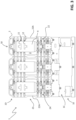
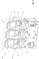
Figures 1-3 are schematic views of a MV vacuum contactor; -
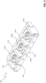
Figures 4-5 are schematic views of the accessory device, according to the invention; -
Figures 6-10 are schematic views of an assembly including a MV vacuum contactor and the accessory device, according to the invention, installed on board said MV vacuum contactor. - With reference to the cited figures, the present invention relates to an
accessory device 100 for a medium-voltage (MV)vacuum contactor 1. - For the purposes of the present application, the term "medium-voltage" (MV) relates to operating voltages at electric power distribution level, which are higher than 1 kV AC and 1.5 kV DC up to some tens of kV, e.g. up to 72 kV AC and 100 kV DC.
-
Figures 1-3 schematically show some views a vacuum contactor for MV electric systems. As it is evident, seen as a whole, theMV vacuum contactor 1 comprises afront side 1A, a pair ofparallel flanks 1B andrear side 1C. Taking as a reference a normal "vertical" installation position of the vacuum contactor, as shown in the cited figures, in theMV vacuum contactor 1, it is possible to identify an upper section ID, at which the electric poles of the contactor are arranged, and a lower section IE, at which actuation means of the contactor are arranged. - The
MV vacuum contactor 1 comprises one or more electric poles 10 (figures 1-3 ). - Preferably, the
MV vacuum contactor 1 is of the multi-phase type, for example of the three-phase type, as shown in the cited figures. In this case, it comprises multiple electric poles, for example three electric poles, which are spaced one from another and preferably arranged in parallel. - Each
electric pole 10 comprises a corresponding insulating housing 2 (e.g. made of thermoplastic or thermosetting materials), which defines an internal space 3 for accommodating the internal components of the electric pole. - The
insulating housing 2 of each electric pole has an elongated shape (e.g. a shape like a parallelepiped with rounded edges as shown in the cited figures) and it has opposite first andsecond sides lateral flanks 23. - The first and
second sides lateral flanks 23 of theinsulating casing 2 are arranged along substantially parallel reference planes, which are substantially perpendicular to the reference planes of the first andsecond sides - Preferably, as shown in the cited figures, the first and
second sides insulating casing 2 are placed, in practice, at the front andrear sides - In general, the
MV vacuum contactor 1 is of the "assembled" type. Theinsulating casing 2 of each electric pole is thus an open insulating casing, which comprises at least anaccess opening 2A. Preferably, as shown in the cited figures, the insulatingcasing 2 comprises anenlarged access opening 2A at the second side 22 (rear side 1C of the contactor). In this case, the insulatingcasing 2 is fully open at thesecond side 22 of the insulating casing. - Each
electric pole 10 comprises afirst pole terminal 8 and asecond pole terminal 9, which may be mechanically fixed to the insulatinghousing 2 by means of flanges. - In operation, the
pole terminals - Advantageously, the
pole terminals casing 2, at thefirst side 21 of this latter (front side 1A of the contactor). For eachelectric pole 10, theMV vacuum contactor 1 comprises a fixedcontact 11 and amovable contact 12, which are electrically connected to the first and second pole terminals, respectively. - The
movable contacts 12 are reversibly movable along suitable displacement axes (e.g. coinciding with the main longitudinal axes of the electric poles), which are preferably parallel one to another and lye on a common displacement plane. - Specifically, the
movable contacts 12 are reversibly movable between a first position (opening position), at which they are decoupled from the corresponding fixedcontacts 11, and a second position (closing position), at which they are coupled to the fixedcontacts 11. - The transition of the
movable contacts 12 from the first position to the second position represents a closing manoeuvre of the MV vacuum contactor whereas the transition of themovable contacts 12 from the second position to the first position represents an opening manoeuvre of the MV vacuum contactor. - Each
electric pole 10 comprises avacuum bottle 4, in which the corresponding fixed andmovable contacts - Preferably, the
vacuum bottles 4 have a cylinder-like shape, as shown in the cited figures. - Preferably, the
vacuum bottles 4 are made of glass or ceramic materials. - As mentioned above, at the lower section IE, the
MV vacuum contactor 1 comprises actuation means to actuate themovable contacts 12 of the electric poles. - Taking as a reference a normal "vertical" installation position of the vacuum contactor, such actuation means are located below the
electric poles 10. - Preferably, said actuation means includes a
movable armature 16, which is mechanically linked to themovable contact 12 of each electric pole through asuitable plunger 17, and at least an actuator 18 (for example an electromagnetic actuator or an electric motor), which is operatively coupled to themovable armature 16. The above-mentioned actuation means may further include additional actuating components, such as springs, kinematic mechanisms and the like, according to the needs. - In general, the
MV vacuum contactor 1 may be arranged according to solutions of known type. Therefore, hereinafter, it will be described only with reference to the technical aspects relevant to the invention, for the sake of brevity. - In the following, the present invention will be described with particular reference to a three-phase vacuum contactor (as shown in the cited figures) for the sake of simplicity only, without intending to limit the scope of the invention in any way.
- As mentioned above, the invention relates to an
accessory device 100 for aMV vacuum contactor 1. - The
accessory device 100 is adapted to be installed on theMV vacuum contactor 1 in order to clamp thevacuum bottles 4 in the electric poles and mechanically bind them to the insulatingcasing 2 of the corresponding electric poles. In this way, a restraint force is exerted on thevacuum bottles 4 and these latter can be firmly maintained in their operating positions, even if they are subject to mechanical stresses or vibrations during the operating life of the vacuum contactor. -
Figures 6-10 show anassembly 200 including the MV vacuum contactor offigures 1-3 and theaccessory device 100 installed on board said vacuum contactor. - The installation of the
accessory device 100 may be carried out during the manufacturing process, the commissioning process or the installation process of theMV vacuum contactor 1 in such a way that this latter is installed on the field already with theaccessory device 100 on board. - The installation of the
accessory device 100 may however be carried out when theMV vacuum contactor 1 already operates on the field, for example during a maintenance intervention. In this case, theaccessory device 100 can be suitably used for retrofitting purposes. - Referring now also to
figures 4-5 , theaccessory device 100 comprises suitable first, second andthird support members more clamp members 104, which are solidly connectable one to another. - The
support members outer surfaces casing 2 of the electric poles (figures 1-3 ) in order to provide support to theclamp members 104. These latter are adapted to clamp thevacuum bottles 4 in the electric poles, so that the vacuum bottles are solidly linked to thesupport members casing 2 of the corresponding electric poles. - Preferably, the
support members clamp members 104 of theaccessory device 100 are made of an electrically insulating material (e.g. a thermoplastic or thermosetting material). - According to the invention, the
accessory device 100 comprises afirst support member 101, which can be coupled to the insulatingcasing 2 of eachelectric pole 10, at the first side 21 (front side) of each insulating casing (figure 8 ). - Preferably, the
first support member 101 is formed by a contoured bar of electrically insulating material, which has an overall length substantially corresponding to the overall width of theelectric poles 10 of the vacuum contactor (between thelateral flanks 1B of this latter). The length of thefirst support member 101 therefore basically depends on the number ofelectric poles 10. - When the
accessory device 100 is installed on the vacuum contactor, thefirst support member 101 is placed across theelectric poles 10 at thefront side 1A of the vacuum contactor, substantially at level of thevacuum bottles 4. - When the
accessory device 100 is installed on the vacuum contactor, thefirst support member 101 is clamped to the insulatingcasing 2 of each electric pole, at thefirst side 101 of this latter. To this aim, thefirst support member 101 preferably comprises one ormore clamping portions 1010, namely one clamping portion for eachelectric pole 10 of the vacuum contactor. - When the
first support member 101 comprises multiple clamping portions 1010 (thevacuum contactor 1 has multiple electric poles), these latter are conveniently spaced one to another depending on the spacings between the electric poles (figures 4-5 ). - Each clamping
portion 1010 defines afirst coupling surface 1011 shaped in such a way to fit a correspondingsecond coupling surface 21A of the insulatingcasing 2, substantially at level of thevacuum bottles 4. In this way, each clampingportion 1010 can be coupled to the insulatingcasing 2 of a correspondingelectric pole 10, at the first side 21 (figures 1 ,6 ,8 ). - When the
accessory device 100 is installed on the vacuum contactor, thefirst support member 101 is joined to eachthird support member 103 of the accessory device. - To this aim, the
first support member 101 preferably comprises a plurality of joiningportions 1012, each of which can be joined to a correspondingthird support member 103 of the accessory device (figures 4-5 ). - Advantageously, the
first support member 101 comprises at least a pair of joiningportions 1012 arranged at its opposite ends. Whenmultiple clamping portions 1010 are present, thefirst support member 101 comprises also one or more joiningportions 1012 in corresponding one or more intermediate positions between said clamping portions (figure 5 ). - Preferably, each joining
portion 1012 defines a first joiningsurface 1013 shaped in such a way to fit a third joiningsurface 1033 of a correspondingthird support member 103 of the accessory device. - According to the invention, the
accessory device 100 comprises asecond support member 102, which can be coupled to the insulatingcasing 2 of eachelectric pole 10, at the second side 22 (rear side 1C of the vacuum contactor) of said insulating casing (figures 7 ,10 ). - Preferably, the
second support member 102 is formed by a bar of electrically insulating material, which has an overall length corresponding to that of thefirst support member 101. When theaccessory device 100 is installed on the vacuum contactor, thesecond support member 102 is placed across theelectric poles 10 at therear side 1C of the vacuum contactor, substantially at level of thevacuum bottles 4 and, preferably, in parallel to the first support member 101 (figures 6-10 ). In particular, thesecond support member 102 is placed across theaccess opening 2A of the insulatingcasing 2 of each electric pole. - Preferably, the
second support member 102 comprisesthird coupling surfaces 1021 that can be coupled to corresponding fourth coupling surfaces 22A of the insulating casing. These latter preferably define theaccess opening 2A of the insulating casing (figures 3 ,7 ,10 ). - As an example, referring to the embodiment shown in the cited figures, since the insulating
casing 2 of each electric pole is fully open at thesecond side 22, thesecond support member 102 is coupled to a pair of side edges of the insulatingcasing 2 of each electric pole, which define theaccess opening 2A. Such side edges form the fourth coupling surfaces 22A of the insulatingcasing 2, which are couplable to correspondingthird coupling surfaces 1021 of thesecond support member 102. - When the
accessory device 100 is installed on the vacuum contactor, thesecond support member 102 is joined to eachthird support member 103 of the accessory device. - Preferably, the
second support member 102 comprises a plurality of second joiningsurfaces 1020, each of which can be coupled to a corresponding fourth joiningsurface 1034 of a third support member 103 (figures 4-5 ). - When the
accessory device 100 is installed on the vacuum contactor, thesecond support member 102 is joined to each clampingmember 104 of the accessory device. - Preferably, the
second support member 102 comprises one or more fifth joiningsurfaces 1023, each of which can be coupled to a corresponding sixth joiningsurface 1041A of a clamping member 104 (figures 4-5 ). - According to the invention, the
accessory device 100 comprises a plurality ofthird support members 103, each of which can be placed at alateral flank 23 of the insulatingcasing 2 of at least anelectric pole 10. - Preferably, each
third support member 103 is formed by a contoured bar of electrically insulating material, which has an overall length corresponding to the lateral thickness of theelectric poles 10 or, more precisely, to the spacing between the first andsecond support members electric poles 10 as theaccessory device 100 is installed on the vacuum contactor. - Preferably, when the
accessory device 100 is installed on the vacuum contactor, thethird support members 103 are placed in pairs at oppositelateral flanks 23 of the insulatingcasing 2 of each electric pole. If the vacuum contactor has multiple electric poles as shown in the cited figures, a singlethird support member 103 is placed at each intermediate spacing between two adjacent electric poles. - In principle, when the
accessory device 100 is installed on the vacuum contactor, thethird support members 103 may be spaced from the insulatingcasing 2 of the electric poles. However, in order to obtain a stronger coupling of theaccessory device 100 with eachelectric pole 10, eachthird support member 103 is coupled to the insulatingcasing 2 of a single electric pole or to the insulatingcasing 2 of two adjacent electric poles. - Preferably, each
third support member 103 comprises one or morefifth coupling surfaces 1030 shaped in such a way to fit corresponding sixth coupling surfaces 23A of the insulatingcasing 2 of one or more electric poles. - The
accessory device 100 comprises opposite terminalthird support members 103 comprising a singlefifth coupling surface 1030 that can be coupled to asixth coupling surface 23A of thelateral flank 23 of the insulatingcasing 2 of a corresponding electric pole (figures 2-4 ). - As it is evident from
figures 6-10 , the terminalthird support members 103 are advantageously arranged at the oppositelateral flanks 1B of the vacuum contactor, when theaccessory device 100 is installed in this latter. - When the vacuum contactor comprises multiple electric poles, the
accessory device 100 comprises one or more intermediatethird support members 103, each including a pair offifth coupling surfaces 1030, conveniently arranged at opposite sides thereof. Thefifth coupling surfaces 1030 can be coupled to correspondingsixth coupling surfaces 23A (which are facing one to another) of the lateral flanks 23 of the insulatingcasings 2 of two adjacent electric poles. As it is evident fromfigures 6-10 , each terminalthird support members 103 is advantageously arranged at a corresponding intermediate position, between two adjacent electric poles. When theaccessory device 100 is installed on the vacuum contactor, thethird support members 103 are arranged transversally (preferably perpendicularly) to the first andsecond members 101, 102 (figures 6-10 ) and are joined to both the first andsecond members support member 103 comprises third and fourth joiningsurfaces 1033, 1034 (figures 4-5 ), which can be coupled to corresponding first joiningsurfaces 1010 of thefirst support member 101 and second joiningsurfaces 1020 of thesecond support member 102, respectively. - According to the invention, the
accessory device 100 comprises one ormore clamping members 104, namely a clamping member for eachelectric pole 10. - When the
accessory device 100 is installed on the vacuum contactor, each clampingmember 104 is partially accommodated in the internal space 3 of a correspondingelectric pole 10 and is coupled to thevacuum bottle 4 of such an electric pole. In order to access the internal space of the correspondingelectric poles 10, each clampingmember 104 passes through theaccess opening 2A of the insulatingcasing 2 at therear side 22 of this latter (rear side 1C of the vacuum contactor). - When the
accessory device 100 is installed on the vacuum contactor, each clampingmember 104 is joined to thesecond support member 102. In this way, each clampingmember 104 is supported by thesecond support member 102, which is in turn supported by the first andthird support members casing 2 of the electric poles. - Preferably, each clamping
member 104 comprises at least afirst collar element 104A. - When the
accessory device 100 is installed on the vacuum contactor, thefirst clamping member 104A passes through theaccess opening 2A of the insulatingcasing 2 of a correspondingelectric pole 10 and is coupled to thevacuum bottle 4 of the corresponding electric pole. - Preferably, the
first collar element 104A comprises a first joiningpart 1041, at which it is joined to thesecond support member 102, and a pair of symmetricfirst clamping arms 1042, which protrude from the joiningpart 1041 and form a semi-circular clamping surface fitting with the outer surface of avacuum bottle 4. - Preferably, the first joining
part 1041 of thefirst collar element 104 comprises a sixth joiningsurface 1041A, which can be joined to a corresponding fifth joiningsurface 1023 of thesecond support member 102. - When the
accessory device 100 is installed on the vacuum contactor, thefirst collar element 104A is inserted in the internal space of the corresponding electric pole through theaccess opening 2A, so that thefirst clamping arms 1042 couple to thevacuum bottle 4 and exert a restraint force on this latter. The first joiningpart 1041 of thefirst collar element 104A protrudes from theaccess opening 2A, so that it can be joined to thesecond support member 102 at the sixth joiningsurface 1041A. - In principle, each clamping
member 104 may comprise the solefirst collar element 104A. Preferably, however, the clampingmember 104 comprises asecond collar element 104B, which can be joined to thefirst collar element 104A. - Preferably, the
second collar element 104B has a structure similar to thefirst collar element 104A. Thesecond collar element 104B thus comprises a second joiningpart 1043 and a pair of symmetricsecond clamping arms 1044 protruding from the second joiningpart 1043 and forming a clamping surface fitting with the outer surface of avacuum bottle 4. - Preferably, when the
accessory device 100 is installed on the vacuum contactor, for each clampingmember 104, the joiningparts second collar elements corresponding vacuum bottle 4 while the first and second clampingarms second collar elements - Preferably, when the
accessory device 100 is installed on the vacuum contactor, for each clampingmember 104, the first and second clampingarms second collar elements first clamping arms 1042 are joined to the free ends of thesecond clamping arms 1044. - When the clamping
member 104 is installed on the vacuum contactor, thesecond collar element 104B is inserted through theaccess opening 2A and is accommodated in the internal space 3 of a correspondingelectric pole 10 at an opposite position with respect to theaccess opening 2A, so that thesecond clamping arms 1044 couple to thevacuum bottle 4 in an opposite position with respect to said access opening (relative to the vacuum bottle 4). - The
first collar element 104A is then inserted in the internal space 3 of the correspondingelectric pole 10 through theaccess opening 2A, so that thefirst clamping arms 1042 couple to thevacuum bottle 4 at an opposite position with respect to the second clamping arms 1044 (relative to the vacuum bottle 4). - The
second collar element 104B is finally joined to thefirst collar element 104A, so that the first and second clampingarms second collar elements vacuum bottle 4. Thefirst collar element 104A is then joined to thesecond support member 102, so that the clampingmember 104 can bind thevacuum bottle 4 to thesecond support member 102. - According to preferred embodiments of the invention, the
accessory device 100 has a fully modular structure. In this case, thesupport members second collar elements support members second collar elements member 104 can be easily manufactured at industrial level through relatively simple mounding processes. - According to preferred embodiments of the invention, the
accessory device 100 comprises: - first fixing
connectors 105 for joining the first, second andthird support members accessory device 100 is installed on the vacuum contactor; -
second fixing connectors 106 for joining each clampingmember 104 to thesecond support member 102, when theaccessory device 100 is installed on the vacuum contactor; -
third fixing connectors 107 for joining the first andsecond collar elements member 104, when theaccessory device 100 is installed on the vacuum contactor. - Preferably, the first, second and third fixing
connectors support members second collar elements member 104 may be joined through connections of different type, for example of snap-fit connections. - As it is evident from the above, a further aspect of the invention relates to a method of installing the
accessory device 100, according to the invention, on avacuum contactor 1. - The steps of the installation method of the
accessory device 100 will be now described with reference to a preferred order of execution, which is particularly suitable for retrofitting vacuum contactors already installed on the field. - The installation method of the
accessory device 100 initially comprises the step of coupling each clampingmember 104 to thevacuum bottle 4 of the correspondingelectric pole 10. Preferably, the step of coupling a clampingmember 104 to thevacuum bottle 4 of the correspondingelectric pole 10 comprises the following steps: - inserting the
second collar element 104B of saidclamping element 104 in the internal space 3 of a correspondingelectric pole 10, through theaccess opening 2A of the insulating casing; - coupling the
second collar element 104B to thevacuum bottle 4 of the correspondingelectric pole 10; - moving the
second collar element 104B, so as to couple thesecond collar element 104B to an outer surface of thevacuum bottle 4, which is located in an opposite position with respect to theaccess opening 2A. The motion of thesecond collar element 104B can be advantageously obtained by rotating thesecond collar element 104B of 180° after this latter has been coupled to thevacuum bottle 4; - inserting the
first collar element 104A of theclamping element 104 in the internal space 3 of the correspondingelectric pole 10, through theaccess opening 2A of the insulatingcasing 2; - coupling the
first collar element 104A to thevacuum bottle 4 of the correspondingelectric pole 10, so that thefirst collar element 104A is coupled to an outer surface of the vacuum bottle, which is located in proximity of theaccess opening 2A. The first andsecond collar elements vacuum bottle 4 at opposite positions (relative to the said vacuum bottle); - joining the
first collar element 104A with thesecond collar element 104B. - The installation method of the
accessory device 100 then advantageously comprises the following steps: - coupling the
second support member 102 to the insulatingcasing 2 of eachelectric pole 10, at thesecond side 22 of said insulating casing; - joining each clamping
member 104 to thesecond support member 22. - The installation method of the
accessory device 100 then advantageously comprises the following steps: - placing a plurality of
third support members 103 in pairs at oppositelateral flanks 23 of the insulatingcasing 2 of eachelectric pole 10; - joining the
third support members 103 to thesecond support member 102. - The installation method of the
accessory device 100 then advantageously comprises the following steps: - coupling the
first support member 101 to the insulatingcasing 2 of eachelectric pole 10, at thefirst side 21 of said insulating casing; - joining the
third support members 103 to thefirst support members 101. - Preferably, the step of coupling the
first support member 101 to the insulatingcasing 2 of eachelectric pole 10 comprises coupling each clampingportion 1010 of thefirst support member 101 with the insulatingcasing 2 of a correspondingelectric pole 10. - Variations to the execution order are however possible, according to the needs, in particular when the
accessory device 100 is installed directly during the manufacturing process, the commissioning process or the installation process of a vacuum contactor. Therefore, in more general terms, the installation method of theaccessory device 100 comprises the following steps (whatever the order): - coupling the
first support member 101 to the insulatingcasing 2 of eachelectric pole 10, at afirst side 21 of said insulating casing; - coupling the
second support member 102 to the insulatingcasing 2 of eachelectric pole 10, at asecond side 22 of said insulating casing, which is opposite to saidfirst side 21; - placing a plurality of
third support members 103 in pairs at oppositelateral flanks 23 of the insulatingcasing 2 of eachelectric pole 10, wherein saidthird support members 103 are arranged transversally to said first and second support members; - coupling each clamping
member 104 to thevacuum bottle 4 of a correspondingelectric pole 10; - joining each clamping
member 104 to thesecond support member 22; - joining the
third support members 103 to the first andsecond support members assembly 200 including: - a medium-
voltage vacuum contactor 1, as described above; - an
accessory device 100, as described above, installed on said vacuum contactor. - As mentioned above, the
assembly 200 may be realized during the manufacturing process, the commissioning process or the installation process of thevacuum contactor 1 or when thevacuum contactor 1 is already installed on the field. - The
accessory device 100, according to the invention, provides remarkable advantages. - When installed on a vacuum contactor, the
accessory device 100 exerts a strong restraint force on thevacuum bottles 4 of the electric poles, which allows firmly maintaining said vacuum bottles in their operating position, even if the internal components of the electric poles are subject to relevant mechanical stresses or vibrations. - The
accessory device 100 therefore allows strengthening the overall structure of a vacuum contactor of the "assembled" type, so that this latter can provide similar performances to a vacuum contactor of the "embedded" type, in terms of robustness and resistance to mechanical stresses. In this way, theaccessory device 100 can remarkably improve the overall reliability of vacuum contactors of the "assembled" type. - The
accessory device 100 is characterized by a high flexibility in use. It can be selectively installed on vacuum contactors that are likely subject to high currents during their operating life, even when these latter are already operating on the field. - The
accessory device 100 is of relatively easy and cheap industrial production and it can be easily installed on a vacuum contactor. As illustrated above, theaccessory device 100 may have a fully modular structure, which greatly simplifies its manufacturing at industrial level and its installation on a vacuum contactor, even when this latter is already operating on the field.
Claims (11)
- An accessory device (100) for a medium-voltage vacuum contactor (1),
wherein said vacuum contactor comprises one or more electric poles, each comprising an open insulating casing (2) and a vacuum bottle (4) accommodated in an internal space (3) defined by said insulating casing,
characterised in that said accessory device (100) comprises a first support member (101), a second support member (102), a plurality of third support members (103) and one or more clamping members (104),
wherein, when said accessory device is installed on said vacuum contactor:- said first support member (101) is coupled to the insulating casing (2) of each electric pole (10), at a first side (21) of said insulating casing;- said second support member (102) is coupled to the insulating casing (2) of each electric pole (10), at a second side (22) of said insulating casing opposite to said first side (21);- each third support member (103) is placed at a lateral flank (23) of the insulating casing (2) of an electric pole (10), said third support members (103) being arranged transversally to said first and second members and joined to said first and second members,- each clamping member is partially accommodated in the internal space (3) of a corresponding electric pole (10) and is coupled to the vacuum bottle (4) of said corresponding electric pole (10),wherein, when said accessory device is installed on said vacuum contactor, each camping member (104) is joined to said second support member (22). - Accessory device, according to claim 1, characterised in that said first support member (101) comprises one or more clamping portions (1010), each clamping portion being coupled to the insulating casing (2) of a corresponding electric pole (10) of said vacuum contactor, when said accessory device is installed on said vacuum contactor.
- Accessory device, according to claim 2, characterised in that said first support member (101) comprises a plurality of joining portions (1012), each joining portion being joined to a corresponding third support member (103), when said accessory device is installed on said vacuum contactor.
- Accessory device, according to one of the previous claims, characterised in that each third support member (103) is coupled to the insulating casing (2) of one or two electric poles (10), when said accessory device is installed on said vacuum contactor.
- Accessory device, according to one of the previous claims, characterised in that each clamping member (104) comprises a first collar element (104A), which is coupled the vacuum bottle (4) of said corresponding electric pole (10), when said accessory device is installed on said vacuum contactor, said first collar element (104A) being joined to said second support member (22), when said accessory device is installed on said vacuum contactor.
- Accessory device, according to claim 5, characterised in that each clamping member (104) comprises a second collar element (104B), which is coupled the vacuum bottle (4) of said corresponding electric pole in an opposite position relative to said first collar element (104A), when said accessory device is installed on said vacuum contactor, said second collar element (104B) being joined to said first collar element (104A), when said accessory device is installed on said vacuum contactor.
- Accessory device, according to one of the previous claims, characterised in that it comprises first fixing connectors (105) joining said first, second and third support members (101, 102, 103), when said accessory device is installed on said vacuum contactor.
- Accessory device, according to one of the previous claims, characterised in that it comprises second fixing connectors (106) joining each clamping member (104) to said second support member (102), when said accessory device is installed on said vacuum contactor.
- Accessory device, according to claims 6 and 8, characterised in that characterised in that it comprises third fixing connectors (107) joining the first and second collar elements (104A, 104B) of each clamping member (104), when said accessory device is installed on said vacuum contactor.
- An assembly (200) including:- a medium-voltage vacuum contactor (1), wherein said vacuum contactor comprises one or more electric poles, each comprising an open insulating casing (2) and a vacuum bottle (4) accommodated in an internal space (3) defined by said insulating casing;- an accessory device (100), according to one of the previous claims, installed on said vacuum contactor (1).
- Method for installing an accessory device (100), according to one of the claims from 1 to 9, on a medium-voltage vacuum contactor (1),
wherein said vacuum contactor comprises one or more electric poles, each comprising an open insulating casing (2) and a vacuum bottle (4) accommodated in the internal space (3) defined by said insulating casing,
characterised in that said method comprises the following claims:- coupling said first support member (101) to the insulating casing (2) of each electric pole (10), at a first side (21) of said insulating casing;- coupling said second support member (102) to the insulating casing (2) of each electric pole (10), at a second side (22) of said insulating casing, which is opposite to said first side (21);- placing a plurality of third support members (103) in pairs at opposite lateral flanks (23) of the insulating casing (2) of each electric pole (10), wherein said third support members (103) are arranged transversally to said first and second support members;- coupling each clamping member (104) to the vacuum bottle (4) of said corresponding electric pole (10);- joining each clamping member (104) to said second support member (22);- joining said third support members (103) to said first and second members (101, 102).
Priority Applications (2)
| Application Number | Priority Date | Filing Date | Title |
|---|---|---|---|
| EP21194234.7A EP4145479B1 (en) | 2021-09-01 | 2021-09-01 | An accessory device for a medium voltage vacuum contactor |
| CN202211064498.9A CN115732264A (en) | 2021-09-01 | 2022-08-31 | Accessory device for medium voltage vacuum contactor |
Applications Claiming Priority (1)
| Application Number | Priority Date | Filing Date | Title |
|---|---|---|---|
| EP21194234.7A EP4145479B1 (en) | 2021-09-01 | 2021-09-01 | An accessory device for a medium voltage vacuum contactor |
Publications (2)
| Publication Number | Publication Date |
|---|---|
| EP4145479A1 true EP4145479A1 (en) | 2023-03-08 |
| EP4145479B1 EP4145479B1 (en) | 2024-02-28 |
Family
ID=77595375
Family Applications (1)
| Application Number | Title | Priority Date | Filing Date |
|---|---|---|---|
| EP21194234.7A Active EP4145479B1 (en) | 2021-09-01 | 2021-09-01 | An accessory device for a medium voltage vacuum contactor |
Country Status (2)
| Country | Link |
|---|---|
| EP (1) | EP4145479B1 (en) |
| CN (1) | CN115732264A (en) |
Citations (3)
| Publication number | Priority date | Publication date | Assignee | Title |
|---|---|---|---|---|
| EP0346603A1 (en) * | 1988-06-14 | 1989-12-20 | Sprecher Energie AG | Vacuum circuit breaker |
| KR20100043364A (en) * | 2008-10-20 | 2010-04-29 | 정영옥 | Load break switch having insulation barrier for non-sf6 gas |
| EP3301700A1 (en) * | 2016-09-29 | 2018-04-04 | ABB Schweiz AG | A medium voltage contactor |
-
2021
- 2021-09-01 EP EP21194234.7A patent/EP4145479B1/en active Active
-
2022
- 2022-08-31 CN CN202211064498.9A patent/CN115732264A/en active Pending
Patent Citations (3)
| Publication number | Priority date | Publication date | Assignee | Title |
|---|---|---|---|---|
| EP0346603A1 (en) * | 1988-06-14 | 1989-12-20 | Sprecher Energie AG | Vacuum circuit breaker |
| KR20100043364A (en) * | 2008-10-20 | 2010-04-29 | 정영옥 | Load break switch having insulation barrier for non-sf6 gas |
| EP3301700A1 (en) * | 2016-09-29 | 2018-04-04 | ABB Schweiz AG | A medium voltage contactor |
Also Published As
| Publication number | Publication date |
|---|---|
| EP4145479B1 (en) | 2024-02-28 |
| CN115732264A (en) | 2023-03-03 |
Similar Documents
| Publication | Publication Date | Title |
|---|---|---|
| US8264306B2 (en) | Movable contactor assembly for current limiting type molded case circuit breaker | |
| EP3411892B1 (en) | Fusible switch disconnect device for dc electrical power system | |
| CN1298550A (en) | Housings for fused switches | |
| CN107533931B (en) | High-voltage compact fusible disconnect switch device with magnetic arc deflection assembly | |
| EP3624153B1 (en) | Gripping group for a switch having an internal compact structure | |
| EP2485229B1 (en) | Flexible shunt for vacuum circuit breaker | |
| EP4145479B1 (en) | An accessory device for a medium voltage vacuum contactor | |
| EP3140847B1 (en) | Circuit breaker with arc extinguishing barrier | |
| EP3140846A1 (en) | Moulded case circuit breaker and method for assembling the same | |
| EP3624161A1 (en) | Electrically controlled switch for high current switching operations with different configurations of fixed terminal contacts | |
| CN101140840A (en) | Circuit breaker | |
| US10692679B2 (en) | Modular fuse removal tool accessory, kit, and systems for fusible disconnect device | |
| JP2012142282A (en) | Bimetal assembly of circuit breaker for wiring | |
| KR101243106B1 (en) | Circuit breaker for load break switch | |
| KR100425188B1 (en) | structure for slide-contacting a moving contact terminal of Circuit Breaker | |
| US20250182992A1 (en) | Modular electrical protection device with control and power modules | |
| KR20100000180U (en) | Terminal Structure of Air Circuit Breaker | |
| WO1998048496A1 (en) | Electrical bus connector apparatus and method | |
| AU729401B2 (en) | Electrical bus connector apparatus and method | |
| KR20170119958A (en) | Miniature circuit breaker | |
| CN201266789Y (en) | Indoor wiring switching equipment | |
| EP1218994A1 (en) | Electrical connection device for power circuit breakers |
Legal Events
| Date | Code | Title | Description |
|---|---|---|---|
| PUAI | Public reference made under article 153(3) epc to a published international application that has entered the european phase |
Free format text: ORIGINAL CODE: 0009012 |
|
| STAA | Information on the status of an ep patent application or granted ep patent |
Free format text: STATUS: THE APPLICATION HAS BEEN PUBLISHED |
|
| AK | Designated contracting states |
Kind code of ref document: A1 Designated state(s): AL AT BE BG CH CY CZ DE DK EE ES FI FR GB GR HR HU IE IS IT LI LT LU LV MC MK MT NL NO PL PT RO RS SE SI SK SM TR |
|
| STAA | Information on the status of an ep patent application or granted ep patent |
Free format text: STATUS: REQUEST FOR EXAMINATION WAS MADE |
|
| 17P | Request for examination filed |
Effective date: 20230622 |
|
| RBV | Designated contracting states (corrected) |
Designated state(s): AL AT BE BG CH CY CZ DE DK EE ES FI FR GB GR HR HU IE IS IT LI LT LU LV MC MK MT NL NO PL PT RO RS SE SI SK SM TR |
|
| GRAP | Despatch of communication of intention to grant a patent |
Free format text: ORIGINAL CODE: EPIDOSNIGR1 |
|
| STAA | Information on the status of an ep patent application or granted ep patent |
Free format text: STATUS: GRANT OF PATENT IS INTENDED |
|
| INTG | Intention to grant announced |
Effective date: 20231018 |
|
| GRAS | Grant fee paid |
Free format text: ORIGINAL CODE: EPIDOSNIGR3 |
|
| GRAA | (expected) grant |
Free format text: ORIGINAL CODE: 0009210 |
|
| STAA | Information on the status of an ep patent application or granted ep patent |
Free format text: STATUS: THE PATENT HAS BEEN GRANTED |
|
| AK | Designated contracting states |
Kind code of ref document: B1 Designated state(s): AL AT BE BG CH CY CZ DE DK EE ES FI FR GB GR HR HU IE IS IT LI LT LU LV MC MK MT NL NO PL PT RO RS SE SI SK SM TR |
|
| REG | Reference to a national code |
Ref country code: GB Ref legal event code: FG4D |
|
| REG | Reference to a national code |
Ref country code: CH Ref legal event code: EP |
|
| REG | Reference to a national code |
Ref country code: DE Ref legal event code: R096 Ref document number: 602021009785 Country of ref document: DE |
|
| REG | Reference to a national code |
Ref country code: IE Ref legal event code: FG4D |
|
| REG | Reference to a national code |
Ref country code: LT Ref legal event code: MG9D |
|
| PG25 | Lapsed in a contracting state [announced via postgrant information from national office to epo] |
Ref country code: IS Free format text: LAPSE BECAUSE OF FAILURE TO SUBMIT A TRANSLATION OF THE DESCRIPTION OR TO PAY THE FEE WITHIN THE PRESCRIBED TIME-LIMIT Effective date: 20240628 |
|
| REG | Reference to a national code |
Ref country code: NL Ref legal event code: MP Effective date: 20240228 |
|
| PG25 | Lapsed in a contracting state [announced via postgrant information from national office to epo] |
Ref country code: LT Free format text: LAPSE BECAUSE OF FAILURE TO SUBMIT A TRANSLATION OF THE DESCRIPTION OR TO PAY THE FEE WITHIN THE PRESCRIBED TIME-LIMIT Effective date: 20240228 |
|
| PG25 | Lapsed in a contracting state [announced via postgrant information from national office to epo] |
Ref country code: GR Free format text: LAPSE BECAUSE OF FAILURE TO SUBMIT A TRANSLATION OF THE DESCRIPTION OR TO PAY THE FEE WITHIN THE PRESCRIBED TIME-LIMIT Effective date: 20240529 |
|
| PG25 | Lapsed in a contracting state [announced via postgrant information from national office to epo] |
Ref country code: HR Free format text: LAPSE BECAUSE OF FAILURE TO SUBMIT A TRANSLATION OF THE DESCRIPTION OR TO PAY THE FEE WITHIN THE PRESCRIBED TIME-LIMIT Effective date: 20240228 Ref country code: NL Free format text: LAPSE BECAUSE OF FAILURE TO SUBMIT A TRANSLATION OF THE DESCRIPTION OR TO PAY THE FEE WITHIN THE PRESCRIBED TIME-LIMIT Effective date: 20240228 Ref country code: RS Free format text: LAPSE BECAUSE OF FAILURE TO SUBMIT A TRANSLATION OF THE DESCRIPTION OR TO PAY THE FEE WITHIN THE PRESCRIBED TIME-LIMIT Effective date: 20240528 |
|
| PG25 | Lapsed in a contracting state [announced via postgrant information from national office to epo] |
Ref country code: ES Free format text: LAPSE BECAUSE OF FAILURE TO SUBMIT A TRANSLATION OF THE DESCRIPTION OR TO PAY THE FEE WITHIN THE PRESCRIBED TIME-LIMIT Effective date: 20240228 |
|
| PG25 | Lapsed in a contracting state [announced via postgrant information from national office to epo] |
Ref country code: RS Free format text: LAPSE BECAUSE OF FAILURE TO SUBMIT A TRANSLATION OF THE DESCRIPTION OR TO PAY THE FEE WITHIN THE PRESCRIBED TIME-LIMIT Effective date: 20240528 Ref country code: NO Free format text: LAPSE BECAUSE OF FAILURE TO SUBMIT A TRANSLATION OF THE DESCRIPTION OR TO PAY THE FEE WITHIN THE PRESCRIBED TIME-LIMIT Effective date: 20240528 Ref country code: NL Free format text: LAPSE BECAUSE OF FAILURE TO SUBMIT A TRANSLATION OF THE DESCRIPTION OR TO PAY THE FEE WITHIN THE PRESCRIBED TIME-LIMIT Effective date: 20240228 Ref country code: LT Free format text: LAPSE BECAUSE OF FAILURE TO SUBMIT A TRANSLATION OF THE DESCRIPTION OR TO PAY THE FEE WITHIN THE PRESCRIBED TIME-LIMIT Effective date: 20240228 Ref country code: IS Free format text: LAPSE BECAUSE OF FAILURE TO SUBMIT A TRANSLATION OF THE DESCRIPTION OR TO PAY THE FEE WITHIN THE PRESCRIBED TIME-LIMIT Effective date: 20240628 Ref country code: HR Free format text: LAPSE BECAUSE OF FAILURE TO SUBMIT A TRANSLATION OF THE DESCRIPTION OR TO PAY THE FEE WITHIN THE PRESCRIBED TIME-LIMIT Effective date: 20240228 Ref country code: GR Free format text: LAPSE BECAUSE OF FAILURE TO SUBMIT A TRANSLATION OF THE DESCRIPTION OR TO PAY THE FEE WITHIN THE PRESCRIBED TIME-LIMIT Effective date: 20240529 Ref country code: FI Free format text: LAPSE BECAUSE OF FAILURE TO SUBMIT A TRANSLATION OF THE DESCRIPTION OR TO PAY THE FEE WITHIN THE PRESCRIBED TIME-LIMIT Effective date: 20240228 Ref country code: ES Free format text: LAPSE BECAUSE OF FAILURE TO SUBMIT A TRANSLATION OF THE DESCRIPTION OR TO PAY THE FEE WITHIN THE PRESCRIBED TIME-LIMIT Effective date: 20240228 Ref country code: BG Free format text: LAPSE BECAUSE OF FAILURE TO SUBMIT A TRANSLATION OF THE DESCRIPTION OR TO PAY THE FEE WITHIN THE PRESCRIBED TIME-LIMIT Effective date: 20240228 |
|
| PG25 | Lapsed in a contracting state [announced via postgrant information from national office to epo] |
Ref country code: PT Free format text: LAPSE BECAUSE OF FAILURE TO SUBMIT A TRANSLATION OF THE DESCRIPTION OR TO PAY THE FEE WITHIN THE PRESCRIBED TIME-LIMIT Effective date: 20240628 Ref country code: PL Free format text: LAPSE BECAUSE OF FAILURE TO SUBMIT A TRANSLATION OF THE DESCRIPTION OR TO PAY THE FEE WITHIN THE PRESCRIBED TIME-LIMIT Effective date: 20240228 |
|
| REG | Reference to a national code |
Ref country code: AT Ref legal event code: MK05 Ref document number: 1662026 Country of ref document: AT Kind code of ref document: T Effective date: 20240228 |
|
| PG25 | Lapsed in a contracting state [announced via postgrant information from national office to epo] |
Ref country code: SE Free format text: LAPSE BECAUSE OF FAILURE TO SUBMIT A TRANSLATION OF THE DESCRIPTION OR TO PAY THE FEE WITHIN THE PRESCRIBED TIME-LIMIT Effective date: 20240228 Ref country code: PT Free format text: LAPSE BECAUSE OF FAILURE TO SUBMIT A TRANSLATION OF THE DESCRIPTION OR TO PAY THE FEE WITHIN THE PRESCRIBED TIME-LIMIT Effective date: 20240628 Ref country code: PL Free format text: LAPSE BECAUSE OF FAILURE TO SUBMIT A TRANSLATION OF THE DESCRIPTION OR TO PAY THE FEE WITHIN THE PRESCRIBED TIME-LIMIT Effective date: 20240228 Ref country code: LV Free format text: LAPSE BECAUSE OF FAILURE TO SUBMIT A TRANSLATION OF THE DESCRIPTION OR TO PAY THE FEE WITHIN THE PRESCRIBED TIME-LIMIT Effective date: 20240228 |
|
| PG25 | Lapsed in a contracting state [announced via postgrant information from national office to epo] |
Ref country code: DK Free format text: LAPSE BECAUSE OF FAILURE TO SUBMIT A TRANSLATION OF THE DESCRIPTION OR TO PAY THE FEE WITHIN THE PRESCRIBED TIME-LIMIT Effective date: 20240228 |
|
| PG25 | Lapsed in a contracting state [announced via postgrant information from national office to epo] |
Ref country code: SM Free format text: LAPSE BECAUSE OF FAILURE TO SUBMIT A TRANSLATION OF THE DESCRIPTION OR TO PAY THE FEE WITHIN THE PRESCRIBED TIME-LIMIT Effective date: 20240228 |
|
| PG25 | Lapsed in a contracting state [announced via postgrant information from national office to epo] |
Ref country code: CZ Free format text: LAPSE BECAUSE OF FAILURE TO SUBMIT A TRANSLATION OF THE DESCRIPTION OR TO PAY THE FEE WITHIN THE PRESCRIBED TIME-LIMIT Effective date: 20240228 Ref country code: EE Free format text: LAPSE BECAUSE OF FAILURE TO SUBMIT A TRANSLATION OF THE DESCRIPTION OR TO PAY THE FEE WITHIN THE PRESCRIBED TIME-LIMIT Effective date: 20240228 |
|
| PG25 | Lapsed in a contracting state [announced via postgrant information from national office to epo] |
Ref country code: AT Free format text: LAPSE BECAUSE OF FAILURE TO SUBMIT A TRANSLATION OF THE DESCRIPTION OR TO PAY THE FEE WITHIN THE PRESCRIBED TIME-LIMIT Effective date: 20240228 |
|
| PG25 | Lapsed in a contracting state [announced via postgrant information from national office to epo] |
Ref country code: SK Free format text: LAPSE BECAUSE OF FAILURE TO SUBMIT A TRANSLATION OF THE DESCRIPTION OR TO PAY THE FEE WITHIN THE PRESCRIBED TIME-LIMIT Effective date: 20240228 |
|
| PG25 | Lapsed in a contracting state [announced via postgrant information from national office to epo] |
Ref country code: SM Free format text: LAPSE BECAUSE OF FAILURE TO SUBMIT A TRANSLATION OF THE DESCRIPTION OR TO PAY THE FEE WITHIN THE PRESCRIBED TIME-LIMIT Effective date: 20240228 Ref country code: SK Free format text: LAPSE BECAUSE OF FAILURE TO SUBMIT A TRANSLATION OF THE DESCRIPTION OR TO PAY THE FEE WITHIN THE PRESCRIBED TIME-LIMIT Effective date: 20240228 Ref country code: RO Free format text: LAPSE BECAUSE OF FAILURE TO SUBMIT A TRANSLATION OF THE DESCRIPTION OR TO PAY THE FEE WITHIN THE PRESCRIBED TIME-LIMIT Effective date: 20240228 Ref country code: EE Free format text: LAPSE BECAUSE OF FAILURE TO SUBMIT A TRANSLATION OF THE DESCRIPTION OR TO PAY THE FEE WITHIN THE PRESCRIBED TIME-LIMIT Effective date: 20240228 Ref country code: DK Free format text: LAPSE BECAUSE OF FAILURE TO SUBMIT A TRANSLATION OF THE DESCRIPTION OR TO PAY THE FEE WITHIN THE PRESCRIBED TIME-LIMIT Effective date: 20240228 Ref country code: CZ Free format text: LAPSE BECAUSE OF FAILURE TO SUBMIT A TRANSLATION OF THE DESCRIPTION OR TO PAY THE FEE WITHIN THE PRESCRIBED TIME-LIMIT Effective date: 20240228 Ref country code: AT Free format text: LAPSE BECAUSE OF FAILURE TO SUBMIT A TRANSLATION OF THE DESCRIPTION OR TO PAY THE FEE WITHIN THE PRESCRIBED TIME-LIMIT Effective date: 20240228 |
|
| REG | Reference to a national code |
Ref country code: DE Ref legal event code: R097 Ref document number: 602021009785 Country of ref document: DE |
|
| PLBE | No opposition filed within time limit |
Free format text: ORIGINAL CODE: 0009261 |
|
| STAA | Information on the status of an ep patent application or granted ep patent |
Free format text: STATUS: NO OPPOSITION FILED WITHIN TIME LIMIT |
|
| 26N | No opposition filed |
Effective date: 20241129 |
|
| REG | Reference to a national code |
Ref country code: DE Ref legal event code: R119 Ref document number: 602021009785 Country of ref document: DE |
|
| PG25 | Lapsed in a contracting state [announced via postgrant information from national office to epo] |
Ref country code: SI Free format text: LAPSE BECAUSE OF FAILURE TO SUBMIT A TRANSLATION OF THE DESCRIPTION OR TO PAY THE FEE WITHIN THE PRESCRIBED TIME-LIMIT Effective date: 20240228 Ref country code: MC Free format text: LAPSE BECAUSE OF FAILURE TO SUBMIT A TRANSLATION OF THE DESCRIPTION OR TO PAY THE FEE WITHIN THE PRESCRIBED TIME-LIMIT Effective date: 20240228 |
|
| REG | Reference to a national code |
Ref country code: CH Ref legal event code: PL |
|
| PG25 | Lapsed in a contracting state [announced via postgrant information from national office to epo] |
Ref country code: LU Free format text: LAPSE BECAUSE OF NON-PAYMENT OF DUE FEES Effective date: 20240901 |
|
| PG25 | Lapsed in a contracting state [announced via postgrant information from national office to epo] |
Ref country code: DE Free format text: LAPSE BECAUSE OF NON-PAYMENT OF DUE FEES Effective date: 20250401 |
|
| REG | Reference to a national code |
Ref country code: BE Ref legal event code: MM Effective date: 20240930 |
|
| PG25 | Lapsed in a contracting state [announced via postgrant information from national office to epo] |
Ref country code: BE Free format text: LAPSE BECAUSE OF NON-PAYMENT OF DUE FEES Effective date: 20240930 |
|
| PG25 | Lapsed in a contracting state [announced via postgrant information from national office to epo] |
Ref country code: FR Free format text: LAPSE BECAUSE OF NON-PAYMENT OF DUE FEES Effective date: 20240930 |
|
| PG25 | Lapsed in a contracting state [announced via postgrant information from national office to epo] |
Ref country code: CH Free format text: LAPSE BECAUSE OF NON-PAYMENT OF DUE FEES Effective date: 20240930 |
|
| PG25 | Lapsed in a contracting state [announced via postgrant information from national office to epo] |
Ref country code: IE Free format text: LAPSE BECAUSE OF NON-PAYMENT OF DUE FEES Effective date: 20240901 |
|
| PGFP | Annual fee paid to national office [announced via postgrant information from national office to epo] |
Ref country code: IT Payment date: 20250923 Year of fee payment: 5 |
|
| PG25 | Lapsed in a contracting state [announced via postgrant information from national office to epo] |
Ref country code: CY Free format text: LAPSE BECAUSE OF FAILURE TO SUBMIT A TRANSLATION OF THE DESCRIPTION OR TO PAY THE FEE WITHIN THE PRESCRIBED TIME-LIMIT; INVALID AB INITIO Effective date: 20210901 |
|
| PG25 | Lapsed in a contracting state [announced via postgrant information from national office to epo] |
Ref country code: HU Free format text: LAPSE BECAUSE OF FAILURE TO SUBMIT A TRANSLATION OF THE DESCRIPTION OR TO PAY THE FEE WITHIN THE PRESCRIBED TIME-LIMIT; INVALID AB INITIO Effective date: 20210901 |