EP4145274A1 - Flexible display screen and display device - Google Patents
Flexible display screen and display device Download PDFInfo
- Publication number
- EP4145274A1 EP4145274A1 EP20932840.0A EP20932840A EP4145274A1 EP 4145274 A1 EP4145274 A1 EP 4145274A1 EP 20932840 A EP20932840 A EP 20932840A EP 4145274 A1 EP4145274 A1 EP 4145274A1
- Authority
- EP
- European Patent Office
- Prior art keywords
- display panel
- reel
- display
- flexible
- layer
- Prior art date
- Legal status (The legal status is an assumption and is not a legal conclusion. Google has not performed a legal analysis and makes no representation as to the accuracy of the status listed.)
- Granted
Links
Images


Classifications
-
- H—ELECTRICITY
- H05—ELECTRIC TECHNIQUES NOT OTHERWISE PROVIDED FOR
- H05K—PRINTED CIRCUITS; CASINGS OR CONSTRUCTIONAL DETAILS OF ELECTRIC APPARATUS; MANUFACTURE OF ASSEMBLAGES OF ELECTRICAL COMPONENTS
- H05K5/00—Casings, cabinets or drawers for electric apparatus
- H05K5/02—Details
- H05K5/0217—Mechanical details of casings
-
- G—PHYSICS
- G06—COMPUTING OR CALCULATING; COUNTING
- G06F—ELECTRIC DIGITAL DATA PROCESSING
- G06F1/00—Details not covered by groups G06F3/00 - G06F13/00 and G06F21/00
- G06F1/16—Constructional details or arrangements
- G06F1/1613—Constructional details or arrangements for portable computers
- G06F1/1633—Constructional details or arrangements of portable computers not specific to the type of enclosures covered by groups G06F1/1615 - G06F1/1626
- G06F1/1637—Details related to the display arrangement, including those related to the mounting of the display in the housing
- G06F1/1652—Details related to the display arrangement, including those related to the mounting of the display in the housing the display being flexible, e.g. mimicking a sheet of paper, or rollable
-
- G—PHYSICS
- G09—EDUCATION; CRYPTOGRAPHY; DISPLAY; ADVERTISING; SEALS
- G09F—DISPLAYING; ADVERTISING; SIGNS; LABELS OR NAME-PLATES; SEALS
- G09F9/00—Indicating arrangements for variable information in which the information is built-up on a support by selection or combination of individual elements
- G09F9/30—Indicating arrangements for variable information in which the information is built-up on a support by selection or combination of individual elements in which the desired character or characters are formed by combining individual elements
- G09F9/301—Indicating arrangements for variable information in which the information is built-up on a support by selection or combination of individual elements in which the desired character or characters are formed by combining individual elements flexible foldable or roll-able electronic displays, e.g. thin LCD, OLED
-
- G—PHYSICS
- G06—COMPUTING OR CALCULATING; COUNTING
- G06F—ELECTRIC DIGITAL DATA PROCESSING
- G06F1/00—Details not covered by groups G06F3/00 - G06F13/00 and G06F21/00
- G06F1/16—Constructional details or arrangements
- G06F1/1613—Constructional details or arrangements for portable computers
- G06F1/1615—Constructional details or arrangements for portable computers with several enclosures having relative motions, each enclosure supporting at least one I/O or computing function
- G06F1/1624—Constructional details or arrangements for portable computers with several enclosures having relative motions, each enclosure supporting at least one I/O or computing function with sliding enclosures, e.g. sliding keyboard or display
-
- G—PHYSICS
- G06—COMPUTING OR CALCULATING; COUNTING
- G06F—ELECTRIC DIGITAL DATA PROCESSING
- G06F1/00—Details not covered by groups G06F3/00 - G06F13/00 and G06F21/00
- G06F1/16—Constructional details or arrangements
- G06F1/1613—Constructional details or arrangements for portable computers
- G06F1/1633—Constructional details or arrangements of portable computers not specific to the type of enclosures covered by groups G06F1/1615 - G06F1/1626
- G06F1/1637—Details related to the display arrangement, including those related to the mounting of the display in the housing
-
- H—ELECTRICITY
- H05—ELECTRIC TECHNIQUES NOT OTHERWISE PROVIDED FOR
- H05K—PRINTED CIRCUITS; CASINGS OR CONSTRUCTIONAL DETAILS OF ELECTRIC APPARATUS; MANUFACTURE OF ASSEMBLAGES OF ELECTRICAL COMPONENTS
- H05K5/00—Casings, cabinets or drawers for electric apparatus
- H05K5/0017—Casings, cabinets or drawers for electric apparatus with operator interface units
-
- H—ELECTRICITY
- H05—ELECTRIC TECHNIQUES NOT OTHERWISE PROVIDED FOR
- H05K—PRINTED CIRCUITS; CASINGS OR CONSTRUCTIONAL DETAILS OF ELECTRIC APPARATUS; MANUFACTURE OF ASSEMBLAGES OF ELECTRICAL COMPONENTS
- H05K5/00—Casings, cabinets or drawers for electric apparatus
- H05K5/0086—Casings, cabinets or drawers for electric apparatus portable, e.g. battery operated apparatus
Definitions
- the present invention is related to the field of display devices, and specifically, to a flexible display screen and a display device.
- liquid crystal display devices In general, liquid crystal display devices, plasma display devices, field emission display devices, light-emitting display devices, etc. have been actively researched as flat panel display devices.
- the liquid crystal display devices and the light-emitting display devices have become a focus because they can realize advantages of mass production technology, ease of production of driving components, and high image quality.
- a conventional rollable display device includes a display panel capable of displaying an image, and a reel; the display panel is then wrapped around the reel.
- friction and electromagnetic interference generated between every instance of the display panel wrapped around the reel during stretching or rewinding greatly affects lifespan of the display panel.
- a purpose of the present invention is to provide a flexible display screen and a display device to solve a problem of a short lifespan of a rollable display panel in the prior art.
- the present invention provides a flexible display screen.
- the flexible display screen includes a display panel, at least one reel mechanism, and a support structure.
- the display panel includes a display surface and a support base away from the display surface.
- the support base is a stepped structure.
- the reel mechanism is disposed on a side of the display panel. A part of the display panel is wrapped around inside the reel mechanism.
- the support structure includes a plurality of support plates.
- the plurality of support plates in the support structure forms a laminated structure, and a step of the support base of the display panel closest to the reel mechanism is disposed on a topmost layer of the plurality of support plates.
- the plurality of support plates in the support structure corresponding thereto is drawn out, and the plurality of support plates drawn out form a stepped structure, which fits the stepped structure of the support base of the expanded display panel, and the display surface of the expanded display panel forms a flat surface.
- the flexible display screen further includes a flexible layer.
- the flexible layer is disposed on the display surface of the display panel. A side of the flexible layer is fixed in the reel mechanism. A length of the display panel is less than a length of the flexible layer.
- the reel mechanism includes a reel provided with a spiral winding structure.
- a side of the flexible layer is fixed to a center of the reel.
- the display panel and the flexible layer are wrapped into the reel mechanism along the reel.
- the reel mechanism further includes at least one coil spring mounted on one end of the reel.
- the reel mechanism further includes balls or rollers.
- the balls or the rollers are disposed on a surface of the reel facing the display panel. A rotation direction of the balls or the rollers is same as a rotation direction of the reel mechanism.
- the reel mechanism further includes a housing.
- the reel is rotationally disposed in the housing.
- An end of a last layer of the plurality of support plates is connected to the housing.
- the housing is provided with an opening. The display panel and the flexible layer extend into the reel mechanism through the opening.
- the flexible display screen further includes a mid-frame case.
- the display panel and the support structure are disposed in the mid-frame case, and the display surface is exposed.
- a side of the flexible layer away from the reel is fixed in the mid-frame case.
- the flexible display screen further includes a battery and a motherboard.
- the battery is disposed in the mid-frame case.
- the motherboard is disposed in the mid-frame case and is connected to the display panel and the battery.
- the display panel further includes a display layer, a touch layer, and a polarizer.
- the display layer is disposed on the support base.
- the touch layer is disposed on a surface of the display layer away from the support base.
- the polarizer is disposed on a surface of the touch layer away from the display layer.
- the present invention also provides a display device.
- the display device includes the flexible display screen as described above.
- the flexible display screen and the display device provided by the present invention configure the reel in the reel mechanism to be the spiral winding structure.
- the display panel is wrapped into the reel along the spiral winding structure of the reel, so that every instance of the display panel wrapped around itself is, thereby reducing friction and electromagnetic interference generated by the display panel wrapped around inside the reel mechanism and extending the lifespan of the display panel.
- a surface of the display panel facing the support structure is configured to be the stepped structure which fits the support structure, so that a step difference between every two support plates in the support structure is eliminated, and the display surface of the display panel is flattened, thereby improving user experience.
- the part can be directly disposed on the other part; alternatively, an intervening part can exist, the part is disposed on the intervening part, and the intervening part is disposed on the other part.
- an intervening part can exist, the part is disposed on the intervening part, and the intervening part is disposed on the other part.
- An embodiment of the present invention provides a display device.
- the display device includes a flexible display screen.
- the flexible display screen provides a display screen for the display device.
- the display device can be any electronic products or components with a display function, such as mobile phones, laptops, televisions, and so on.
- the flexible display screen includes a display panel 10, a reel mechanism 40, and a support structure 30.
- the support structure 30 includes three support plates 31, the support plates 31 are laminated atop each other.
- One or more slide rails are configured to realize movable installation between every two support plates 31, so that a stepped expansion shown in FIG. 2 can be realized between the support plates 31.
- the slide rails can be section-by-section locking slide rails, so that the support structure 30 can be expanded layer by layer. When the support structure 30 is collapsed, it is shown as in FIG. 3 . When the support structure 30 is expanded, it is shown as in FIG. 4 .
- the display panel 10 includes a display layer 11, a touch layer 12, a polarizer 13, and a support base 14.
- the support base 14, the display layer 11, the touch layer 12, and the polarizer 13 are sequentially laminated.
- a surface of the display panel 10 away from the support base 14 is its display surface.
- the touch layer 12 is disposed on a surface of the display layer 11.
- the polarizer 13 is disposed on a surface of the touch layer 12 away from the display layer 11.
- the display layer 11 and the touch layer 12 can be attached with an optical adhesive, which increases integration and stability between the display layer 11 and the touch layer 12 and prevents peeling.
- the touch layer 12 and the polarizer 13 can be attached with a pressure sensitive adhesive 16, which increases adhesion between the touch layer 12 and the polarizer 13 without affecting pressure sensing of the touch layer 12.
- the display layer 11 is configured to emit light and provide a display screen.
- the touch layer 12 is configured to implement touch control.
- the polarizer 13 is configured to filter and polarize the light emitted by the display layer 11 to help the display panel 10 to image.
- the support base 14 is disposed on a surface of the display layer 11 away from the touch layer 12, and it can also be attached to the display layer 11 through an adhesive layer 15.
- the support base 14 is also disposed on the support plates 31 of the support structure 30.
- a surface of the support base 14 facing the supporting structure 30 is provided with a stepped structure. Each step in the stepped structure corresponds to each support plate 31 in the support structure 30.
- the support plates 31 in the support structure 30 are drawn out layer by layer with a laminated structure. Also, every two support plates 31 forms a step difference, so that the stepped structure is formed accordingly and fits the stepped structure of the support base 14.
- a step of the support base 14 of the display panel 10 closest to the reel mechanism 40 is disposed on a topmost layer of the support plates 31, so as to support the display panel 10. In this way, the display surface of the expanded display panel 10 remains unaffected by uneven step differences between the support plates 31, improving user experience.
- the flexible display screen further includes a flexible layer 20.
- the flexible layer 20 is disposed on the display surface of the display panel 10, that is, the flexible layer 20 is disposed on a surface of the polarizer 13 away from the touch layer 12.
- the flexible layer 20 and the polarizer 13 can be attached with the adhesive layer 15.
- a length of the flexible layer 20 is greater than a length of the display panel 10, so that two ends of the flexible layer 20 have extension ends 21 longer than the display panel 10.
- the reel mechanism 40 is disposed on a side of the display panel 10. A part of the display panel 10 and the flexible layer 20 are wrapped around inside the reel mechanism 40. As shown in FIG. 5 , the reel mechanism 40 includes a reel 41, two coil springs 42, and a housing 43.
- the reel 41 is provided with a spiral winding structure.
- An extension end 21 of the flexible layer 20 is fixed to a center of the reel 41.
- a part of the flexible layer 20 and the display panel 10 disposed on the flexible layer 20 are wrapped into the reel 41 along the spiral winding structure of the reel 41. Overlaying instances of the display panel 10 wrapped around the reel 41 are separated by the spiral winding structure and are prevented from contacting each other, thereby reducing friction and electromagnetic interference generated while drawing out the display panel 10 and extending the lifespan of the display panel 10.
- a surface of the reel 41 contacting the display panel 10 can be provided with a plurality of rollers.
- the rollers can be rotationally disposed on the reel 41.
- a rotation direction of the rollers is same as a rotation direction of the reel 41, which can reduce friction between the display panel 10 and the reel 41, thereby preventing damage due to friction and further extending the lifespan of the display panel 10.
- the rollers can be replaced with balls.
- a structure of disposing the balls and a rotation direction of the balls are similar to those of the rollers, so they are not described herein. All other embodiments obtained by a person of ordinary skill in the art based on the embodiments of the present invention without creative efforts shall fall within the protection scope of the present invention.
- the two coil springs 42 are respectively mounted on two ends of the reel 41.
- the reel 41 drives and tensions the coil springs 42, which generates a reaction force opposite to a rotation direction of the reel 41.
- the reaction force can tension the flexible layer 20 when the flexible display screen is expanded, and the display panel 10 disposed under the flexible layer 20 is also under tension, so that display images does not wrinkle.
- the reaction force of the coil spring 42 drives the reel 41 to rotate, so that the flexible layer 20 and the display panel 10, which are drawn out, are rewrapped into the reel 41.
- the reel 41 and the coil springs 42 are rotationally disposed in the housing 43.
- the housing 43 includes a shell 44 and two caps 45.
- the shell 44 is a hollow cylinder.
- the two caps 45 are respectively disposed on two ends of the shell 44.
- the shell 44 of the housing 43 is provided with an opening 46.
- the flexible layer 20 and the display panel 10 extend into the reel mechanism 40 through the opening 46.
- An end of a last layer of the support plates 31 is disposed under the opening 46.
- the housing 43 is configured to protect and support the reel 41 and the coil springs 42.
- the flexible display screen further includes a motherboard 50, a power supply 60, and a mid-frame case 70.
- the motherboard 50, the power supply 60, and the display panel 10 are electrically connected to each other.
- the motherboard 50 is configured to control the display panel 10 to display images.
- the power supply 60 is configured to provide operating energy.
- the display panel 10 and the support structure 30 are disposed in the mid-frame case 70.
- An extension end 21 of the flexible layer 20 away from the reel mechanism 40 is fixed in the mid-frame case 70.
- the display surface is exposed.
- the motherboard 50 and the power supply are also disposed in the mid-frame case 70.
- the flexible display screen and the display device provided by the present invention configure a surface of the display panel 10 facing the support structure 30 to be the stepped structure which fits the support structure 30, so that a step difference between every two support plates 31 in the support structure 30 is eliminated, and the display surface of the display panel 10 is flattened, thereby improving user experience.
- the reel 41 in the reel mechanism 40 is configured to be the spiral winding structure.
- the display panel 10 is wrapped into the reel 41 along the spiral winding structure of the reel 41, so that every instance of the display panel 10 wrapped around itself is not in contact with each other, thereby reducing friction and electromagnetic interference generated by the display panel 10 wrapped around inside the reel mechanism 40 and extending the lifespan of the display panel 10.
- the rollers or the balls are also disposed on a contact surface between the reel 41 and the display panel 10 to reduce friction between the display panel 10 and the reel 41, preventing scratch damage and further extending lifespan of the flexible display screen.
Landscapes
- Engineering & Computer Science (AREA)
- Theoretical Computer Science (AREA)
- Physics & Mathematics (AREA)
- General Physics & Mathematics (AREA)
- Computer Hardware Design (AREA)
- Microelectronics & Electronic Packaging (AREA)
- Human Computer Interaction (AREA)
- General Engineering & Computer Science (AREA)
- Mathematical Physics (AREA)
- Devices For Indicating Variable Information By Combining Individual Elements (AREA)
Abstract
Description
- The present invention is related to the field of display devices, and specifically, to a flexible display screen and a display device.
- In general, liquid crystal display devices, plasma display devices, field emission display devices, light-emitting display devices, etc. have been actively researched as flat panel display devices. However, the liquid crystal display devices and the light-emitting display devices have become a focus because they can realize advantages of mass production technology, ease of production of driving components, and high image quality.
- Recently, with regard to technical deficiencies of the flat panel display devices, it is particularly necessary to intensify research and development on rollable or foldable display product structures that can attract consumers' attention. A conventional rollable display device includes a display panel capable of displaying an image, and a reel; the display panel is then wrapped around the reel. However, in such a rollable display device, friction and electromagnetic interference generated between every instance of the display panel wrapped around the reel during stretching or rewinding greatly affects lifespan of the display panel.
- Therefore, it is necessary to research and develop a flexible display device capable of realizing a rollable display or a foldable display without the above problems.
- A purpose of the present invention is to provide a flexible display screen and a display device to solve a problem of a short lifespan of a rollable display panel in the prior art.
- In order to achieve the above purpose, the present invention provides a flexible display screen. The flexible display screen includes a display panel, at least one reel mechanism, and a support structure. The display panel includes a display surface and a support base away from the display surface. The support base is a stepped structure. The reel mechanism is disposed on a side of the display panel. A part of the display panel is wrapped around inside the reel mechanism. The support structure includes a plurality of support plates.
- When the display panel is drawn out, the plurality of support plates in the support structure forms a laminated structure, and a step of the support base of the display panel closest to the reel mechanism is disposed on a topmost layer of the plurality of support plates. When the display panel is expanded, the plurality of support plates in the support structure corresponding thereto is drawn out, and the plurality of support plates drawn out form a stepped structure, which fits the stepped structure of the support base of the expanded display panel, and the display surface of the expanded display panel forms a flat surface.
- Furthermore, the flexible display screen further includes a flexible layer. The flexible layer is disposed on the display surface of the display panel. A side of the flexible layer is fixed in the reel mechanism. A length of the display panel is less than a length of the flexible layer.
- Furthermore, the reel mechanism includes a reel provided with a spiral winding structure. A side of the flexible layer is fixed to a center of the reel. The display panel and the flexible layer are wrapped into the reel mechanism along the reel.
- Furthermore, the reel mechanism further includes at least one coil spring mounted on one end of the reel.
- Furthermore, the reel mechanism further includes balls or rollers. The balls or the rollers are disposed on a surface of the reel facing the display panel. A rotation direction of the balls or the rollers is same as a rotation direction of the reel mechanism.
- Furthermore, the reel mechanism further includes a housing. The reel is rotationally disposed in the housing. An end of a last layer of the plurality of support plates is connected to the housing. The housing is provided with an opening. The display panel and the flexible layer extend into the reel mechanism through the opening.
- Furthermore, the flexible display screen further includes a mid-frame case. The display panel and the support structure are disposed in the mid-frame case, and the display surface is exposed. A side of the flexible layer away from the reel is fixed in the mid-frame case.
- Furthermore, the flexible display screen further includes a battery and a motherboard. The battery is disposed in the mid-frame case. The motherboard is disposed in the mid-frame case and is connected to the display panel and the battery.
- Furthermore, the display panel further includes a display layer, a touch layer, and a polarizer. The display layer is disposed on the support base. The touch layer is disposed on a surface of the display layer away from the support base. The polarizer is disposed on a surface of the touch layer away from the display layer.
- The present invention also provides a display device. The display device includes the flexible display screen as described above.
- The flexible display screen and the display device provided by the present invention configure the reel in the reel mechanism to be the spiral winding structure. The display panel is wrapped into the reel along the spiral winding structure of the reel, so that every instance of the display panel wrapped around itself is, thereby reducing friction and electromagnetic interference generated by the display panel wrapped around inside the reel mechanism and extending the lifespan of the display panel. Also, a surface of the display panel facing the support structure is configured to be the stepped structure which fits the support structure, so that a step difference between every two support plates in the support structure is eliminated, and the display surface of the display panel is flattened, thereby improving user experience.
- In order to describe technical solutions in the present invention clearly, drawings to be used in the description of embodiments will be described briefly below. Obviously, drawings described below are only for some embodiments of the present invention, and other drawings can be obtained by those skilled in the art based on these drawings without creative efforts.
-
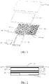
FIG. 1 is a schematic diagram of components of a flexible display screen in an embodiment of the present invention. -
FIG. 2 is a schematic diagram of layers of the flexible display screen in an embodiment of the present invention. -
FIG. 3 is a three-dimensional view of a collapsed support structure of the flexible display screen in an embodiment of the present invention. -
FIG. 4 is a three-dimensional view of an expended support structure of the flexible display screen in an embodiment of the present invention. -
FIG. 5 is a schematic diagram of components of a reel mechanism in an embodiment of the present invention. -
FIG. 6 is a schematic cross-sectional view of the reel mechanism in an embodiment of the present invention. -
-
display panel 10,display layer 11, -
touch layer 12,polarizer 13, -
support base 14,adhesive layer 15, - pressure
sensitive adhesive 16,flexible layer 20, -
extension end 21,support structure 30, -
support plate 31,reel mechanism 40, -
reel 41,coil spring 42, - housing 43,
shell 44, -
cap 45, opening 46, -
motherboard 50,power supply 60, -
mid-frame case 70. - A preferred embodiment of the present invention will be introduced with reference to appended drawings as follows to demonstrate that the present invention can be implemented. The embodiment of the present invention can be fully introduced to those skilled in the art to make technical contents clearer and easier to understand. The present invention can be embodied in many different forms of embodiment, and the scope of protection of the present invention is not limited to the embodiments set forth herein.
- In the appended drawings, structurally identical components are designated by the same reference numerals, and structurally or functionally similar components throughout are designated by similar numerical reference numerals. The dimensions and thicknesses of each component shown in the drawings are arbitrarily shown. The size and thickness of each component are not limited, and for the sake of clarity, the thickness of the components is exaggerated somewhat in some places in the drawings.
- Direction terms mentioned by the present invention, for example "upper," "lower," "front," "rear," "left," "right," "inner," "outer," "side," etc. are merely directions in the appended drawings for only explaining and illustrating the present invention. The orientation or positional relationship is only for the convenience of describing the present invention and simplifying the description, and does not indicate or imply that the device or element referred to must have a specific orientation, structure and operation in a specific orientation, and should not be viewed as limitations of the present invention. In addition, terms "first," "second," and "third" are used for descriptive purposes only, and cannot be understood as indicating or implying relative importance or implicitly indicating the number of technical features indicated.
- When some part is described to be "on" another part, the part can be directly disposed on the other part; alternatively, an intervening part can exist, the part is disposed on the intervening part, and the intervening part is disposed on the other part. When a part is described to be "installed on" or "connected to" another part, it can be understood that the parts are directly "installed" or "connected" to each other, alternatively it is understood that one part is "installed" or "connected" to the other part through an intervening part.
- An embodiment of the present invention provides a display device. The display device includes a flexible display screen. The flexible display screen provides a display screen for the display device. The display device can be any electronic products or components with a display function, such as mobile phones, laptops, televisions, and so on.
- As shown in
FIG. 1 , the flexible display screen includes adisplay panel 10, areel mechanism 40, and asupport structure 30. - The
support structure 30 includes threesupport plates 31, thesupport plates 31 are laminated atop each other. One or more slide rails are configured to realize movable installation between every twosupport plates 31, so that a stepped expansion shown inFIG. 2 can be realized between thesupport plates 31. The slide rails can be section-by-section locking slide rails, so that thesupport structure 30 can be expanded layer by layer. When thesupport structure 30 is collapsed, it is shown as inFIG. 3 . When thesupport structure 30 is expanded, it is shown as inFIG. 4 . - As shown in
FIG. 2 , thedisplay panel 10 includes adisplay layer 11, atouch layer 12, apolarizer 13, and asupport base 14. Thesupport base 14, thedisplay layer 11, thetouch layer 12, and thepolarizer 13 are sequentially laminated. A surface of thedisplay panel 10 away from thesupport base 14 is its display surface. Thetouch layer 12 is disposed on a surface of thedisplay layer 11. Thepolarizer 13 is disposed on a surface of thetouch layer 12 away from thedisplay layer 11. Thedisplay layer 11 and thetouch layer 12 can be attached with an optical adhesive, which increases integration and stability between thedisplay layer 11 and thetouch layer 12 and prevents peeling. thetouch layer 12 and thepolarizer 13 can be attached with a pressuresensitive adhesive 16, which increases adhesion between thetouch layer 12 and thepolarizer 13 without affecting pressure sensing of thetouch layer 12. Thedisplay layer 11 is configured to emit light and provide a display screen. Thetouch layer 12 is configured to implement touch control. Thepolarizer 13 is configured to filter and polarize the light emitted by thedisplay layer 11 to help thedisplay panel 10 to image. - The
support base 14 is disposed on a surface of thedisplay layer 11 away from thetouch layer 12, and it can also be attached to thedisplay layer 11 through anadhesive layer 15. Thesupport base 14 is also disposed on thesupport plates 31 of thesupport structure 30. A surface of thesupport base 14 facing the supportingstructure 30 is provided with a stepped structure. Each step in the stepped structure corresponds to eachsupport plate 31 in thesupport structure 30. - When the
display panel 10 is expanded, thesupport plates 31 in thesupport structure 30 are drawn out layer by layer with a laminated structure. Also, every twosupport plates 31 forms a step difference, so that the stepped structure is formed accordingly and fits the stepped structure of thesupport base 14. A step of thesupport base 14 of thedisplay panel 10 closest to thereel mechanism 40 is disposed on a topmost layer of thesupport plates 31, so as to support thedisplay panel 10. In this way, the display surface of the expandeddisplay panel 10 remains unaffected by uneven step differences between thesupport plates 31, improving user experience. - The flexible display screen further includes a
flexible layer 20. Theflexible layer 20 is disposed on the display surface of thedisplay panel 10, that is, theflexible layer 20 is disposed on a surface of thepolarizer 13 away from thetouch layer 12. Theflexible layer 20 and thepolarizer 13 can be attached with theadhesive layer 15. A length of theflexible layer 20 is greater than a length of thedisplay panel 10, so that two ends of theflexible layer 20 have extension ends 21 longer than thedisplay panel 10. - The
reel mechanism 40 is disposed on a side of thedisplay panel 10. A part of thedisplay panel 10 and theflexible layer 20 are wrapped around inside thereel mechanism 40. As shown inFIG. 5 , thereel mechanism 40 includes areel 41, twocoil springs 42, and a housing 43. - As shown in
FIG. 6 , thereel 41 is provided with a spiral winding structure. Anextension end 21 of theflexible layer 20 is fixed to a center of thereel 41. A part of theflexible layer 20 and thedisplay panel 10 disposed on theflexible layer 20 are wrapped into thereel 41 along the spiral winding structure of thereel 41. Overlaying instances of thedisplay panel 10 wrapped around thereel 41 are separated by the spiral winding structure and are prevented from contacting each other, thereby reducing friction and electromagnetic interference generated while drawing out thedisplay panel 10 and extending the lifespan of thedisplay panel 10. - In another embodiment of the present invention, a surface of the
reel 41 contacting thedisplay panel 10 can be provided with a plurality of rollers. The rollers can be rotationally disposed on thereel 41. A rotation direction of the rollers is same as a rotation direction of thereel 41, which can reduce friction between thedisplay panel 10 and thereel 41, thereby preventing damage due to friction and further extending the lifespan of thedisplay panel 10. - In another embodiment, the rollers can be replaced with balls. A structure of disposing the balls and a rotation direction of the balls are similar to those of the rollers, so they are not described herein. All other embodiments obtained by a person of ordinary skill in the art based on the embodiments of the present invention without creative efforts shall fall within the protection scope of the present invention.
- The two
coil springs 42 are respectively mounted on two ends of thereel 41. When the flexible display screen is drawn out, theflexible layer 20 and thedisplay panel 10 extend outward from thereel 41 and drive thereel 41 to rotate. Thereel 41 drives and tensions the coil springs 42, which generates a reaction force opposite to a rotation direction of thereel 41. The reaction force can tension theflexible layer 20 when the flexible display screen is expanded, and thedisplay panel 10 disposed under theflexible layer 20 is also under tension, so that display images does not wrinkle. When the flexible display screen is collapsed, the reaction force of thecoil spring 42 drives thereel 41 to rotate, so that theflexible layer 20 and thedisplay panel 10, which are drawn out, are rewrapped into thereel 41. - The
reel 41 and the coil springs 42 are rotationally disposed in the housing 43. The housing 43 includes ashell 44 and twocaps 45. Theshell 44 is a hollow cylinder. The twocaps 45 are respectively disposed on two ends of theshell 44. Theshell 44 of the housing 43 is provided with anopening 46. Theflexible layer 20 and thedisplay panel 10 extend into thereel mechanism 40 through theopening 46. An end of a last layer of thesupport plates 31 is disposed under theopening 46. Thus, when thedisplay panel 10 is expanded by thereel mechanism 40, thesupport plates 31 can also be driven to expand at the same time. The housing 43 is configured to protect and support thereel 41 and the coil springs 42. - The flexible display screen further includes a
motherboard 50, apower supply 60, and amid-frame case 70. Themotherboard 50, thepower supply 60, and thedisplay panel 10 are electrically connected to each other. themotherboard 50 is configured to control thedisplay panel 10 to display images. Thepower supply 60 is configured to provide operating energy. Thedisplay panel 10 and thesupport structure 30 are disposed in themid-frame case 70. Anextension end 21 of theflexible layer 20 away from thereel mechanism 40 is fixed in themid-frame case 70. The display surface is exposed. Themotherboard 50 and the power supply are also disposed in themid-frame case 70. - The flexible display screen and the display device provided by the present invention configure a surface of the
display panel 10 facing thesupport structure 30 to be the stepped structure which fits thesupport structure 30, so that a step difference between every twosupport plates 31 in thesupport structure 30 is eliminated, and the display surface of thedisplay panel 10 is flattened, thereby improving user experience. Also, thereel 41 in thereel mechanism 40 is configured to be the spiral winding structure. Thedisplay panel 10 is wrapped into thereel 41 along the spiral winding structure of thereel 41, so that every instance of thedisplay panel 10 wrapped around itself is not in contact with each other, thereby reducing friction and electromagnetic interference generated by thedisplay panel 10 wrapped around inside thereel mechanism 40 and extending the lifespan of thedisplay panel 10. In addition, the rollers or the balls are also disposed on a contact surface between thereel 41 and thedisplay panel 10 to reduce friction between thedisplay panel 10 and thereel 41, preventing scratch damage and further extending lifespan of the flexible display screen. - Although the present invention herein has been described with reference to particular embodiments, it should be understood that these embodiments are merely illustrative of the principles and applications of the present invention. It is therefore to be understood that numerous modifications can be made to the illustrative embodiments and that other arrangements can be devised without departing from the spirit and scope of the present invention as defined by the appended claims. It will be appreciated that the various dependent claims and the features set forth therein can be combined in different ways than presented in the initial claims. It will also be appreciated that the features described in connection with individual embodiments can be shared with others of the described embodiments.
Claims (10)
- A flexible display screen, comprising:a display panel comprising a display surface and a support base away from the display surface, wherein the support base is a stepped structure;at least one reel mechanism disposed on a side of the display panel, wherein a part of the display panel is wrapped around inside the reel mechanism; anda support structure comprising a plurality of support plates;wherein when the display panel is drawn out, the plurality of support plates in the support structure forms a laminated structure, and a step of the support base of the display panel closest to the reel mechanism is disposed on a topmost layer of the plurality of support plates; andwherein when the display panel is expanded, the plurality of support plates in the support structure corresponding thereto is drawn out, and the plurality of support plates drawn out form a stepped structure, which fits the stepped structure of the support base of the expanded display panel, and the display surface of the expanded display panel forms a flat surface.
- The flexible display screen according to claim 1, further comprising:a flexible layer disposed on the display surface of the display panel;wherein a side of the flexible layer is fixed in the reel mechanism, and a length of the display panel is less than a length of the flexible layer.
- The flexible display screen according to claim 2, wherein the reel mechanism comprises:a reel provided with a spiral winding structure;wherein a side of the flexible layer is fixed to a center of the reel, and the display panel and the flexible layer are wrapped into the reel mechanism along the reel.
- The flexible display screen according to claim 3, wherein the reel mechanism further comprises:
at least one coil spring mounted on one end of the reel. - The flexible display screen according to claim 3, wherein the reel mechanism further comprises:balls disposed on a surface of the reel facing the display panel; orrollers disposed on a surface of the reel facing the display panel;wherein a rotation direction of the balls or the rollers is same as a rotation direction of the reel mechanism.
- The flexible display screen according to claim 3, wherein the reel mechanism further comprises:a housing;wherein the reel is rotationally disposed in the housing, and an end of a last layer of the plurality of support plates is connected to the housing; andwherein the housing is provided with an opening, and the display panel and the flexible layer extend into the reel mechanism through the opening.
- The flexible display screen according to claim 2, further comprising:a mid-frame case;wherein the display panel and the support structure are disposed in the mid-frame case, and the display surface is exposed; andwherein a side of the flexible layer away from the reel is fixed in the mid-frame case.
- The flexible display screen according to claim 7, further comprising:a battery disposed in the mid-frame case; anda motherboard disposed in the mid-frame case and connected to the display panel and the battery.
- The flexible display screen according to claim 1, wherein the display panel further comprises:a display layer disposed on the support base;a touch layer disposed on a surface of the display layer away from the support base; anda polarizer disposed on a surface of the touch layer away from the display layer.
- A display device, comprising the flexible display screen according to claim 1.
Applications Claiming Priority (2)
| Application Number | Priority Date | Filing Date | Title |
|---|---|---|---|
| CN202010345374.2A CN111383539B (en) | 2020-04-27 | 2020-04-27 | Flexible display screen and display device |
| PCT/CN2020/095696 WO2021217797A1 (en) | 2020-04-27 | 2020-06-12 | Flexible display screen and display device |
Publications (3)
| Publication Number | Publication Date |
|---|---|
| EP4145274A1 true EP4145274A1 (en) | 2023-03-08 |
| EP4145274A4 EP4145274A4 (en) | 2024-05-15 |
| EP4145274B1 EP4145274B1 (en) | 2026-04-08 |
Family
ID=77559118
Family Applications (1)
| Application Number | Title | Priority Date | Filing Date |
|---|---|---|---|
| EP20932840.0A Active EP4145274B1 (en) | 2020-04-27 | 2020-06-12 | Flexible display screen and display device |
Country Status (2)
| Country | Link |
|---|---|
| US (2) | US11116091B1 (en) |
| EP (1) | EP4145274B1 (en) |
Families Citing this family (2)
| Publication number | Priority date | Publication date | Assignee | Title |
|---|---|---|---|---|
| CN111383540B (en) * | 2020-04-30 | 2022-04-08 | 上海天马微电子有限公司 | Display device capable of being curled |
| CN112002226B (en) * | 2020-08-17 | 2022-02-22 | 武汉华星光电半导体显示技术有限公司 | Flexible display device |
Family Cites Families (31)
| Publication number | Priority date | Publication date | Assignee | Title |
|---|---|---|---|---|
| US7830333B2 (en) * | 2006-12-13 | 2010-11-09 | Palo Alto Research Center Incorporated | Slide-out information display |
| JP2010526335A (en) * | 2007-04-25 | 2010-07-29 | ポリマー、ビジョン、リミテッド | Electronic device with flexible display with edge protector |
| CN101689004B (en) * | 2007-05-09 | 2013-10-23 | 创造者科技有限公司 | Electronic device with cleaning unit for flexible display |
| TWI441115B (en) * | 2007-11-21 | 2014-06-11 | Creator Technology Bv | An electronic device with a flexible display |
| US8711566B2 (en) * | 2011-09-02 | 2014-04-29 | Microsoft Corporation | Expandable mobile device |
| US9829925B2 (en) * | 2014-05-21 | 2017-11-28 | Youseob Lim | Flexible display apparatus having roller that rotates by unfolding operation-force of user |
| KR102304310B1 (en) * | 2015-02-13 | 2021-09-23 | 삼성디스플레이 주식회사 | Rollable display device |
| CN104683522A (en) * | 2015-03-31 | 2015-06-03 | 上海摩软通讯技术有限公司 | Mobile terminal |
| US9772657B2 (en) * | 2015-04-30 | 2017-09-26 | Samsung Electronics Co., Ltd. | Rollable display device |
| KR102384576B1 (en) | 2015-06-15 | 2022-04-08 | 엘지디스플레이 주식회사 | Flexible display apparatus |
| KR101638167B1 (en) * | 2015-07-07 | 2016-07-08 | 장진우 | portable device having flexible display panel |
| US9625948B2 (en) * | 2015-08-24 | 2017-04-18 | Apple Inc. | Electronic devices with retractable displays |
| CN105118389B (en) | 2015-09-29 | 2019-06-14 | 京东方科技集团股份有限公司 | Support backplane and curved display |
| TWI574479B (en) * | 2015-11-23 | 2017-03-11 | 緯創資通股份有限公司 | Telescopic device having carrier member, carrier member and cable thereof |
| KR102527214B1 (en) | 2016-05-04 | 2023-04-28 | 삼성디스플레이 주식회사 | Rollable display device |
| CN107545349A (en) | 2016-06-28 | 2018-01-05 | 国网天津市电力公司 | A kind of Data Quality Analysis evaluation model towards electric power big data |
| KR102591365B1 (en) * | 2016-09-12 | 2023-10-19 | 삼성디스플레이 주식회사 | Expandable display device |
| KR102528529B1 (en) * | 2016-10-06 | 2023-05-03 | 삼성디스플레이 주식회사 | Rollable display device |
| CN208044999U (en) | 2018-02-09 | 2018-11-02 | 深圳市柔宇科技有限公司 | Flexible display apparatus |
| CN208044998U (en) | 2018-02-09 | 2018-11-02 | 深圳市柔宇科技有限公司 | Flexible display apparatus |
| KR102269604B1 (en) * | 2018-02-23 | 2021-06-28 | 삼성전자주식회사 | Electronic device including movable flexible display |
| KR102458690B1 (en) * | 2018-04-04 | 2022-10-25 | 삼성전자주식회사 | Electronic device having wireless charging module and flexible display |
| KR102477229B1 (en) * | 2018-07-30 | 2022-12-13 | 삼성디스플레이 주식회사 | Display device and moving method thereof |
| US10820433B2 (en) * | 2019-01-31 | 2020-10-27 | Lg Electronics Inc. | Flexible display device |
| KR102845067B1 (en) * | 2019-02-14 | 2025-08-13 | 엘지전자 주식회사 | Mobile terminal |
| CN109903679B (en) | 2019-03-07 | 2023-06-27 | 京东方科技集团股份有限公司 | Foldable supporting structure, preparation method thereof and display device |
| CN110534024A (en) | 2019-09-10 | 2019-12-03 | 青岛海信移动通信技术股份有限公司 | rollable display |
| CN110599911B (en) | 2019-10-10 | 2021-08-24 | 云谷(固安)科技有限公司 | Rolling device and flexible display device |
| EP4047912B1 (en) * | 2019-10-18 | 2025-06-18 | LG Electronics, Inc. | Mobile terminal |
| WO2021132748A1 (en) * | 2019-12-24 | 2021-07-01 | 엘지전자 주식회사 | Flexible display device |
| CN111047995B (en) | 2019-12-30 | 2022-07-26 | 厦门天马微电子有限公司 | Flexible display device |
-
2020
- 2020-06-12 US US16/963,512 patent/US11116091B1/en active Active
- 2020-06-12 EP EP20932840.0A patent/EP4145274B1/en active Active
-
2021
- 2021-08-24 US US17/409,874 patent/US11690185B2/en active Active
Also Published As
| Publication number | Publication date |
|---|---|
| US11116091B1 (en) | 2021-09-07 |
| US11690185B2 (en) | 2023-06-27 |
| EP4145274B1 (en) | 2026-04-08 |
| US20210385957A1 (en) | 2021-12-09 |
| EP4145274A4 (en) | 2024-05-15 |
Similar Documents
| Publication | Publication Date | Title |
|---|---|---|
| CN111383539B (en) | Flexible display screen and display device | |
| US10582628B2 (en) | Display device | |
| US10783809B2 (en) | Rollable display device | |
| US10863633B2 (en) | Display device | |
| CN111161633B (en) | Display device | |
| US11809231B2 (en) | Display device with flexible display panel connected to transmission mechanism | |
| TWI773113B (en) | Display device | |
| CN114500704B (en) | Electronic devices | |
| US10390443B2 (en) | Display device | |
| US10983562B2 (en) | Flexible display device | |
| US10856426B2 (en) | Rollable display device | |
| CN110910767B (en) | Flexible display screen and display device | |
| CN114900572B (en) | Housing components and electronic equipment | |
| US10111344B2 (en) | Display device | |
| US11690185B2 (en) | Flexible display screen and display device | |
| KR102578842B1 (en) | Display device | |
| WO2022000672A1 (en) | Flexible display device | |
| US12154463B2 (en) | Display module and display apparatus including the same having a base with a coupling portion | |
| CN112599020B (en) | Flexible display device and electronic equipment | |
| CN115424526A (en) | Flexible display device | |
| CN215298700U (en) | rollable display | |
| CN115240556A (en) | Flexible screen assembly and electronic equipment | |
| CN120690105A (en) | Display device |
Legal Events
| Date | Code | Title | Description |
|---|---|---|---|
| STAA | Information on the status of an ep patent application or granted ep patent |
Free format text: STATUS: THE INTERNATIONAL PUBLICATION HAS BEEN MADE |
|
| PUAI | Public reference made under article 153(3) epc to a published international application that has entered the european phase |
Free format text: ORIGINAL CODE: 0009012 |
|
| STAA | Information on the status of an ep patent application or granted ep patent |
Free format text: STATUS: REQUEST FOR EXAMINATION WAS MADE |
|
| 17P | Request for examination filed |
Effective date: 20211104 |
|
| AK | Designated contracting states |
Kind code of ref document: A1 Designated state(s): AL AT BE BG CH CY CZ DE DK EE ES FI FR GB GR HR HU IE IS IT LI LT LU LV MC MK MT NL NO PL PT RO RS SE SI SK SM TR |
|
| DAV | Request for validation of the european patent (deleted) | ||
| DAX | Request for extension of the european patent (deleted) | ||
| REG | Reference to a national code |
Ref country code: DE Ref legal event code: R079 Free format text: PREVIOUS MAIN CLASS: G06F0009300000 Ipc: G06F0001160000 Ref document number: 602020070249 Country of ref document: DE |
|
| A4 | Supplementary search report drawn up and despatched |
Effective date: 20240411 |
|
| RIC1 | Information provided on ipc code assigned before grant |
Ipc: G09F 9/30 20060101ALI20240405BHEP Ipc: G06F 1/16 20060101AFI20240405BHEP |
|
| GRAP | Despatch of communication of intention to grant a patent |
Free format text: ORIGINAL CODE: EPIDOSNIGR1 |
|
| STAA | Information on the status of an ep patent application or granted ep patent |
Free format text: STATUS: GRANT OF PATENT IS INTENDED |
|
| INTG | Intention to grant announced |
Effective date: 20251127 |
|
| GRAS | Grant fee paid |
Free format text: ORIGINAL CODE: EPIDOSNIGR3 |
|
| GRAA | (expected) grant |
Free format text: ORIGINAL CODE: 0009210 |
|
| STAA | Information on the status of an ep patent application or granted ep patent |
Free format text: STATUS: THE PATENT HAS BEEN GRANTED |
|
| AK | Designated contracting states |
Kind code of ref document: B1 Designated state(s): AL AT BE BG CH CY CZ DE DK EE ES FI FR GB GR HR HU IE IS IT LI LT LU LV MC MK MT NL NO PL PT RO RS SE SI SK SM TR |
|
| P01 | Opt-out of the competence of the unified patent court (upc) registered |
Free format text: CASE NUMBER: UPC_APP_0008479_4145274/2026 Effective date: 20260303 |
|
| REG | Reference to a national code |
Ref country code: CH Ref legal event code: F10 Free format text: ST27 STATUS EVENT CODE: U-0-0-F10-F00 (AS PROVIDED BY THE NATIONAL OFFICE) Effective date: 20260408 Ref country code: GB Ref legal event code: FG4D |
|
| REG | Reference to a national code |
Ref country code: DE Ref legal event code: R096 Ref document number: 602020070249 Country of ref document: DE |