EP4145244A1 - Electronic device - Google Patents
Electronic device Download PDFInfo
- Publication number
- EP4145244A1 EP4145244A1 EP21795700.0A EP21795700A EP4145244A1 EP 4145244 A1 EP4145244 A1 EP 4145244A1 EP 21795700 A EP21795700 A EP 21795700A EP 4145244 A1 EP4145244 A1 EP 4145244A1
- Authority
- EP
- European Patent Office
- Prior art keywords
- main body
- foldable main
- detection part
- capacitors
- foldable
- Prior art date
- Legal status (The legal status is an assumption and is not a legal conclusion. Google has not performed a legal analysis and makes no representation as to the accuracy of the status listed.)
- Granted
Links
Images


Classifications
-
- G—PHYSICS
- G06—COMPUTING OR CALCULATING; COUNTING
- G06F—ELECTRIC DIGITAL DATA PROCESSING
- G06F1/00—Details not covered by groups G06F3/00 - G06F13/00 and G06F21/00
- G06F1/16—Constructional details or arrangements
- G06F1/1613—Constructional details or arrangements for portable computers
- G06F1/1615—Constructional details or arrangements for portable computers with several enclosures having relative motions, each enclosure supporting at least one I/O or computing function
- G06F1/1616—Constructional details or arrangements for portable computers with several enclosures having relative motions, each enclosure supporting at least one I/O or computing function with folding flat displays, e.g. laptop computers or notebooks having a clamshell configuration, with body parts pivoting to an open position around an axis parallel to the plane they define in closed position
-
- G—PHYSICS
- G01—MEASURING; TESTING
- G01B—MEASURING LENGTH, THICKNESS OR SIMILAR LINEAR DIMENSIONS; MEASURING ANGLES; MEASURING AREAS; MEASURING IRREGULARITIES OF SURFACES OR CONTOURS
- G01B7/00—Measuring arrangements characterised by the use of electric or magnetic techniques
- G01B7/30—Measuring arrangements characterised by the use of electric or magnetic techniques for measuring angles or tapers; for testing the alignment of axes
-
- G—PHYSICS
- G06—COMPUTING OR CALCULATING; COUNTING
- G06F—ELECTRIC DIGITAL DATA PROCESSING
- G06F1/00—Details not covered by groups G06F3/00 - G06F13/00 and G06F21/00
- G06F1/16—Constructional details or arrangements
- G06F1/1613—Constructional details or arrangements for portable computers
- G06F1/1615—Constructional details or arrangements for portable computers with several enclosures having relative motions, each enclosure supporting at least one I/O or computing function
- G06F1/1622—Constructional details or arrangements for portable computers with several enclosures having relative motions, each enclosure supporting at least one I/O or computing function with enclosures rotating around an axis perpendicular to the plane they define or with ball-joint coupling, e.g. PDA with display enclosure orientation changeable between portrait and landscape by rotation with respect to a coplanar body enclosure
-
- G—PHYSICS
- G06—COMPUTING OR CALCULATING; COUNTING
- G06F—ELECTRIC DIGITAL DATA PROCESSING
- G06F1/00—Details not covered by groups G06F3/00 - G06F13/00 and G06F21/00
- G06F1/16—Constructional details or arrangements
- G06F1/1613—Constructional details or arrangements for portable computers
- G06F1/1633—Constructional details or arrangements of portable computers not specific to the type of enclosures covered by groups G06F1/1615 - G06F1/1626
- G06F1/1637—Details related to the display arrangement, including those related to the mounting of the display in the housing
- G06F1/1641—Details related to the display arrangement, including those related to the mounting of the display in the housing the display being formed by a plurality of foldable display components
-
- G—PHYSICS
- G06—COMPUTING OR CALCULATING; COUNTING
- G06F—ELECTRIC DIGITAL DATA PROCESSING
- G06F1/00—Details not covered by groups G06F3/00 - G06F13/00 and G06F21/00
- G06F1/16—Constructional details or arrangements
- G06F1/1613—Constructional details or arrangements for portable computers
- G06F1/1633—Constructional details or arrangements of portable computers not specific to the type of enclosures covered by groups G06F1/1615 - G06F1/1626
- G06F1/1675—Miscellaneous details related to the relative movement between the different enclosures or enclosure parts
-
- G—PHYSICS
- G06—COMPUTING OR CALCULATING; COUNTING
- G06F—ELECTRIC DIGITAL DATA PROCESSING
- G06F1/00—Details not covered by groups G06F3/00 - G06F13/00 and G06F21/00
- G06F1/16—Constructional details or arrangements
- G06F1/1613—Constructional details or arrangements for portable computers
- G06F1/1633—Constructional details or arrangements of portable computers not specific to the type of enclosures covered by groups G06F1/1615 - G06F1/1626
- G06F1/1675—Miscellaneous details related to the relative movement between the different enclosures or enclosure parts
- G06F1/1677—Miscellaneous details related to the relative movement between the different enclosures or enclosure parts for detecting open or closed state or particular intermediate positions assumed by movable parts of the enclosure, e.g. detection of display lid position with respect to main body in a laptop, detection of opening of the cover of battery compartment
-
- G—PHYSICS
- G06—COMPUTING OR CALCULATING; COUNTING
- G06F—ELECTRIC DIGITAL DATA PROCESSING
- G06F1/00—Details not covered by groups G06F3/00 - G06F13/00 and G06F21/00
- G06F1/16—Constructional details or arrangements
- G06F1/1613—Constructional details or arrangements for portable computers
- G06F1/1633—Constructional details or arrangements of portable computers not specific to the type of enclosures covered by groups G06F1/1615 - G06F1/1626
- G06F1/1675—Miscellaneous details related to the relative movement between the different enclosures or enclosure parts
- G06F1/1681—Details related solely to hinges
-
- G—PHYSICS
- G09—EDUCATION; CRYPTOGRAPHY; DISPLAY; ADVERTISING; SEALS
- G09F—DISPLAYING; ADVERTISING; SIGNS; LABELS OR NAME-PLATES; SEALS
- G09F9/00—Indicating arrangements for variable information in which the information is built-up on a support by selection or combination of individual elements
- G09F9/30—Indicating arrangements for variable information in which the information is built-up on a support by selection or combination of individual elements in which the desired character or characters are formed by combining individual elements
- G09F9/301—Indicating arrangements for variable information in which the information is built-up on a support by selection or combination of individual elements in which the desired character or characters are formed by combining individual elements flexible foldable or roll-able electronic displays, e.g. thin LCD, OLED
-
- G—PHYSICS
- G01—MEASURING; TESTING
- G01D—MEASURING NOT SPECIALLY ADAPTED FOR A SPECIFIC VARIABLE; ARRANGEMENTS FOR MEASURING TWO OR MORE VARIABLES NOT COVERED IN A SINGLE OTHER SUBCLASS; TARIFF METERING APPARATUS; MEASURING OR TESTING NOT OTHERWISE PROVIDED FOR
- G01D5/00—Mechanical means for transferring the output of a sensing member; Means for converting the output of a sensing member to another variable where the form or nature of the sensing member does not constrain the means for converting; Transducers not specially adapted for a specific variable
- G01D5/12—Mechanical means for transferring the output of a sensing member; Means for converting the output of a sensing member to another variable where the form or nature of the sensing member does not constrain the means for converting; Transducers not specially adapted for a specific variable using electric or magnetic means
- G01D5/14—Mechanical means for transferring the output of a sensing member; Means for converting the output of a sensing member to another variable where the form or nature of the sensing member does not constrain the means for converting; Transducers not specially adapted for a specific variable using electric or magnetic means influencing the magnitude of a current or voltage
- G01D5/24—Mechanical means for transferring the output of a sensing member; Means for converting the output of a sensing member to another variable where the form or nature of the sensing member does not constrain the means for converting; Transducers not specially adapted for a specific variable using electric or magnetic means influencing the magnitude of a current or voltage by varying capacitance
- G01D5/241—Mechanical means for transferring the output of a sensing member; Means for converting the output of a sensing member to another variable where the form or nature of the sensing member does not constrain the means for converting; Transducers not specially adapted for a specific variable using electric or magnetic means influencing the magnitude of a current or voltage by varying capacitance by relative movement of capacitor electrodes
Definitions
- the present disclosure relates to the field of communications technologies, and in particular, to an electronic device.
- the prior art provides a scheme to detect a folding angle by using a light emitter and a receiver. As shown in FIG. 1 , a first foldable main body 11, a second foldable main body 12, a light emitter 13, and a plurality of light receivers 14 arranged at intervals are used to determine a folding angle.
- the first foldable main body 11 is rotationally connected to the second foldable main body 12; the light emitter 13 is fixed relative to the first foldable main body 11; the plurality of light receivers 14 are fixed relative to the second foldable main body 12; the light emitter 13 can be selectively matched with one of the plurality of light receivers 14; and a processing unit is configured to: determine a target light receiver that is currently matched with the light emitter, and determine a folding angle of an electronic device with a foldable screen based on preset position information of the light receiver and the light emitter.
- the existing light sensor-based scheme requires a great quantity of light receivers.
- space of a rotating shaft is limited, a quantity of light receivers that can be disposed is limited.
- a great quantity of light receivers are used, costs are increased; and in a case that the great quantity of light receivers are disposed on a relatively small rotating shaft, difficulty in design is increased, and a great quantity of detection port resources of a central processing unit (Central Processing Unit, CPU) chip are occupied.
- CPU Central Processing Unit
- an existing method for detecting a folding angle of an electronic device has the problems of high costs, great design difficulty, and high occupation of detection port resources.
- Embodiments of the present disclosure provides an electronic device, to resolve the problems of high costs, great design difficulty, and high occupation of detection port resources of a method for detecting a folding angle of an electronic device in the prior art.
- An embodiment of the present disclosure provides an electronic device, including:
- a first detection part is fixed relative to one of two foldable main bodies; a second detection part is fixed relative to the other one of the two foldable main bodies; a detection loop is formed when the first detection part is switchably connected to a plurality of capacitors of the second detection part; and a relative angle between the first foldable main body and the second foldable main body is detected by the first detection part and the second detection part. Therefore, costs and space occupation can be reduced; and design difficulty can be decreased. In addition, detection for any angle can be realized, which improves detection performance.
- an electronic device As shown in FIG. 2 and FIG. 3 , the electronic device includes:
- the electronic device in this embodiment of the present disclosure includes the first foldable main body 1, the second foldable main body 2 disposed on a side of the first foldable main body 1, the rotating shaft 3 disposed between the first foldable main body 1 and the second foldable main body 2, and the detection assembly 4.
- the electronic device may be a mobile phone, a tablet personal computer, a laptop computer, a personal digital assistant (PDA), a mobile Internet device (MID), a wearable device, or the like.
- PDA personal digital assistant
- MID mobile Internet device
- the first foldable main body 1 is rotationally connected to the second foldable main body 2 by the rotating shaft 3.
- the first foldable main body 1 and the second foldable main body 2 may not be particularly distinguished.
- a left foldable main body is the first foldable main body, and a right foldable main body is the second foldable main body; or the left foldable main body is the second foldable main body, and the right foldable main body is the first foldable main body.
- This embodiment of the present disclosure is described by using an example in which the left foldable main body is the first foldable main body and the right foldable main body is the second foldable main body.
- a case in which the left foldable main body is the second foldable main body and the right foldable main body is the first foldable main body is similar to the above case. Details are not described herein again.
- the detection assembly 4 includes a first detection part 41 and a second detection part 42.
- the two detection parts are disposed at different positions.
- the first detection part 41 is fixed relative to the first foldable main body 1
- the second detection part 42 is fixed relative to the second foldable main body 2
- the first detection part 41 is fixed relative to the second foldable main body 2
- the second detection part 42 is fixed relative to the first foldable main body 1.
- the second detection part 42 includes a plurality of capacitors 421 that are disposed at intervals in a rotating direction of the first foldable main body 1 and the second foldable main body 2.
- the second foldable main body 2 may rotate clockwise or counterclockwise.
- Distances between all adjacent capacitors 421 may be the same or different. All capacitances of the capacitors 421 are different.
- the capacitors 421 may be pF-grade capacitors.
- the first detection part 41 can be switchably connected to the plurality of capacitors 421. In a case that the first detection part 41 is connected to one of the capacitors 421, the first detection part 41 is conducted with the second detection part 42 to form the detection loop.
- the relative angle between the first foldable main body 1 and the second foldable main body 2 can be detected by the detection assembly 4.
- Each capacitor 421 may correspond to a folding angle between the first foldable main body 1 and the second foldable main body 2.
- the relative angle between the first foldable main body 1 and the second foldable main body 2 can be determined based on a capacitor 421 that is connected to the first detection part 41.
- a first detection part is fixed relative to one of two foldable main bodies; a second detection part is fixed relative to the other one of the two foldable main bodies; and a detection loop for detecting the relative angle between the first foldable main body and the second foldable main body is formed when the first detection part is switchably connected to a plurality of capacitors of the second detection part. Therefore, costs and space occupation can be reduced; and design difficulty can be decreased. In addition, detection for any angle can be realized, which improves detection performance.
- the first foldable main body 1 is fixed relative to the rotating shaft 3
- the second foldable main body 2 is rotationally mounted on the rotating shaft 3
- the first detection part 41 is mounted on the first foldable main body 1 or the rotating shaft 3
- the second detection part 42 is fixedly connected to the second foldable main body 2.
- the first foldable main body 1 may be fixed relative to and connected to the rotating shaft 3, and the second foldable main body 2 is rotationally mounted on the rotating shaft 3. Because the first foldable main body 1 is fixed relative to the rotating shaft 3, the second foldable main body 2 can rotate relative to the first foldable main body 1.
- a form of a structure in which the first detection part 41 is fixed relative to one of the two foldable main bodies, and the second detection part 42 is fixed relative to the other one of the two foldable main bodies is as follows: The first detection part 41 is mounted on the first foldable main body 1, and the second detection part 42 is fixedly connected to the second foldable main body 2; or the first detection part 41 is mounted on the rotating shaft 3, and the second detection part 42 is fixedly connected to the second foldable main body 2.
- the first detection part 41 may be disposed on an end surface, connected to the rotating shaft 3, of the first foldable main body 1, or disposed in the first foldable main body 1, provided that the first detection part 41 can protrude from the first foldable main body 1 and be connected to the second detection part 42. Accordingly, for a case in which the first detection part 41 is mounted on the rotating shaft 3, in a case that the first detection part 41 is an elastic component, the first detection part 41 may be disposed at any position of the rotating shaft 3, thereby being connected to the second detection part 42.
- the plurality of capacitors 421 included by the second detection part 42 may be disposed on an end surface, in contact with the rotating shaft 3, of the second detection part 42.
- a cylinder sleeving the rotating shaft 3 is disposed in the second foldable main body 2, the plurality of capacitors 421 are disposed in a circumferential direction of the cylinder, such that the first detection part 41 can be switchably connected to the plurality of capacitors 421 in a rotating process of the second foldable main body 2.
- the distances between all the adjacent capacitors 421 may be the same or different. Capacitances of all the capacitors 421 are different. In a case that the distances between all the adjacent capacitors 421 are the same, capacitances between all the adjacent capacitors 421 may increase or decrease at a preset gradient.
- the first foldable main body is fixed relative to the rotating shaft; the second foldable main body can rotate related to the rotating shaft; and the first detection part disposed on the first foldable main body or the rotating shaft can be switchably connected to the plurality of capacitors by rotating the second foldable main body. Therefore, the detection loop can be formed to detect the relative angle between the two foldable main bodies.
- the electronic device further includes a circuit board 5.
- a through hole is formed in the circuit board 5, the rotating shaft 3 penetrates the through hole, the plurality of capacitors 421 are disposed on the circuit board 5 at intervals in the circumferential direction of the rotating shaft 3, the circuit board 5 is fixed relative to the second foldable main body 2, and the first detection part 41 is fixed relative to the first foldable main body 1.
- the electronic device further includes the circuit board 5.
- the circuit board 5 may be a printed circuit board (PCB).
- a through hole may be formed in the circuit board 5.
- the rotating shaft 3 is connected to the circuit board 5 by penetrating the through hole.
- the capacitors 421 may be disposed on the circuit board 5 at intervals in the circumferential direction of the rotating shaft 3. Because the circuit board 5 is fixed relative to the second foldable main body 2, rotation of the second foldable main body 2 can drive the circuit board 5 to rotate.
- the first detection part 41 can be switchably connected to the plurality of capacitors 421 in a rotating process of the circuit board 5, where the first detection part 41 is fixed relative to the first foldable main body 1. Because the first foldable main body 1 is fixed relative to the rotating shaft 3, the first detection part 41 may be disposed on the first foldable main body 1 or the rotating shaft 3.
- the circuit board 5 may be circular or of other shapes.
- the through hole is formed in a central position or other positions of the circuit board.
- the rotating shaft 3 may penetrate the through hole in the circuit board, thereby mounting the circuit board on the rotating shaft 3.
- each capacitor 421 may be determined according to a layout of the plurality of capacitors 421, such that when the first detection part 41 is in contact with the capacitor 421, a corresponding angle between the two foldable main bodies can be determined.
- the plurality of capacitors 421 are disposed on the circuit board 5 at intervals in the circumferential direction of the rotating shaft 3.
- the plurality of capacitors 421 may be disposed around the rotating shaft 3 by one circle.
- the first detection part 41 in a process of rotating the second foldable main body 2 relative to the rotating shaft 3, the first detection part 41 can be switchably connected to the plurality of capacitors 421.
- the detection loop can be formed when the first detection part 41 is connected to the capacitor 421. Therefore, the angle between the two foldable main bodies can be detected.
- a circumference corresponding to the rotating shaft 3 may be divided into equal parts or different arcs.
- a length of each arc is required for determining an angle corresponding to each capacitor 421.
- arcs corresponding to all the adjacent capacitors 421 are equal.
- the capacitances of all the adjacent capacitors 421 may increase or decrease at a preset gradient. Accordingly, angles corresponding to all the adjacent capacitors 421 may increase or decrease by a preset angle difference, such that differences between the angles corresponding to all the adjacent capacitors 421 are equal.
- the following uses a specific embodiment to describe the case in which the plurality of capacitors 421 divide the circumference corresponding to the rotating shaft 3 into equal parts.
- the circuit board 5 rotates around the rotating shaft 3 by a same angle under the driving of the second foldable main body 2, and the first detection part 41 is disposed on the first foldable main body 1 or the rotating shaft 3, and can be switchably connected to the plurality of capacitors 421 disposed on the circuit board 5, thereby determining the angle between the two foldable main bodies.
- a number and a corresponding angle of a capacitor may be determined in the following process: First, determine, as 1, a number of a capacitor corresponding to 0° on the circumference corresponding to the rotating shaft; then, determine lengths of arcs between the capacitor and the other capacitors; obtain central angles corresponding to the lengths of the arcs; determine the central angles as angles corresponding to the other capacitors; and sequentially determine capacitor numbers in ascending order of the angles, where the capacitor numbers are positively correlated with the angles, and capacitances of the capacitors are positively correlated with the capacitor numbers.
- the lengths of the arcs between adjacent capacitors 421 may increase sequentially. In this case, differences between angles corresponding to the adjacent capacitors 421 increase sequentially.
- the capacitors 421 may also be numbered one by one. To facilitate memorization, it may be specified that the capacitances of the capacitors 421 sequentially increase or decrease in an extending direction of the arcs; or a corresponding relation between the capacitances of the capacitors 421 and numbers is established, for example, a capacitor 421 whose capacitance is greater has a greater number. In a case that the capacitor 421 is in contact with the first detection part 41, a number is determined based on an obtained capacitance. Then, the angle between the two foldable main bodies is determined.
- the circuit board is disposed on the rotating shaft, and the plurality of capacitors are disposed on the circuit board in the circumferential direction of the rotating shaft, and are driven to rotate when the second foldable main body rotates around the rotating shaft, such that the first detection part can be switchably connected to the plurality of capacitors. Therefore, the detection loop can be formed to detect the relative angle between the two foldable main bodies.
- the first foldable main body 1 can rotate relative to the rotating shaft 3
- the second foldable main body 2 can rotate relative to the rotating shaft 3
- the first detection part 41 is mounted on the first foldable main body 1
- the second detection part 42 is fixedly connected to the second foldable main body 2.
- both the first foldable main body 1 and the second foldable main body 2 can rotate relative to the rotating shaft 3.
- the first detection part 41 is mounted on the first foldable main body 1
- the second detection part 42 is fixedly connected to the second foldable main body 2.
- the first detection part 41 disposed on the first foldable main body 1 rotates with the first foldable main body 1, and is switchably connected to the plurality of capacitors 421 disposed on the second foldable main body 2 in sequence. Therefore, the detection loop can be formed to detect the relative angle between the two foldable main bodies.
- the detection loop can be formed to detect the relative angle between the two foldable main bodies.
- the detection loop can be formed to detect the relative angle between the two foldable main bodies.
- Each capacitor 421 may correspond to a folding angle between the first foldable main body 1 and the second foldable main body 2.
- the relative angle between the first foldable main body 1 and the second foldable main body 2 can be determined based on a capacitor 421 that is connected to the first detection part 41.
- the first foldable main body and the second foldable main body rotate relative to the rotating shaft; and the first detection part is switchably connected to the plurality of capacitors by rotating the second foldable main body and/or the first foldable main body. Therefore, the detection loop can be formed to detect the relative angle between the two foldable main bodies.
- the first detection part 41 includes a conductive spring plate 411, the conductive spring plate 411 is provided with a protruding part, and the protruding part is switchably connected to the plurality of capacitors 421.
- the first detection part 41 includes the conductive spring plate 411 that is provided with the protruding part; and the conductive spring plate 411 is switchably connected to the plurality of capacitors 421 through the protruding part.
- the first foldable main body 1 is rotationally connected to the second foldable main body 2 by the rotating shaft 3; the first detection part 41 is fixed relative to one of the two foldable main bodies; and the plurality of capacitors 421 are fixed relative to the other one of the two foldable main bodies. Therefore, the conductive spring plate 411 can be switchably connected to the plurality of capacitors 421 in sequence through the protruding part.
- the conductive spring plate provided with the protruding part can be conveniently connected to the capacitor when the conductive spring plate is disposed at any position. Therefore, the position of the conductive spring plate is diversified.
- the second detection part 42 further includes a plurality of conductive parts 422, each of the conductive parts 422 is connected to one of the capacitors 421, and in a case that the protruding part is connected to one of the conductive parts 422, the conductive spring plate 411, the conductive part 422, and the capacitor 421 are conducted with one another to form the detection loop.
- the second detection part 42 includes the plurality of capacitors 421 and the plurality of conductive parts 422.
- Each conductive part 422 may include a copper-exposed region.
- a quantity of the capacitors 421 is the same as a quantity of the conductive parts 422.
- Each capacitor 421 is correspondingly connected to one conductive part 422.
- the protruding part of the conductive spring plate 411 is connected to one conductive part 422.
- the protruding part is connected to the copper-exposed region of the conductive part 422.
- the conductive spring plate 411 can be connected to the capacitor 421. Therefore, the conductive spring plate 411, the conductive part 422, and the capacitor 421 form the detection loop. This enables the conductive spring plate 411 to be switchably connected to the plurality of capacitors 421 in sequence.
- the conductive spring plate 411 may be a metal spring plate.
- the conductive spring plate 411 is an antenna spring plate. Connection between the conductive spring plate 411 and the conductive part 422 is implemented via contact between the metal spring plate and the copper-exposed region.
- the conductive spring plate, the conductive part, and the capacitor are conducted to form the detection loop. Therefore, in a case that the conductive spring plate is in contact with the conductive part, the conductive spring plate can be switchably connected to the plurality of capacitors in sequence.
- each capacitor 421 is grounded. Forming of the detection loop can be guaranteed by setting the capacitor 421 to be grounded.
- the detection loop further includes a capacitance reader 61 and a controller 62 connected to the capacitance reader 61.
- the capacitance reader 61 obtains a current capacitance of one of the capacitors 421 that is connected to the first detection part 41, and the controller 62 stores a target capacitance and obtains the relative angle between the first foldable main body 1 and the second foldable main body 2 based on the current capacitance and the target capacitance.
- the detection loop further includes the capacitance reader 61 and the controller 62.
- the capacitance reader 61 and the controller 62 may be disposed on the first foldable main body 1, the second foldable main body 2, or the rotating shaft 3.
- the capacitance reader 61 may be connected to the first detection part 41, and be configured to read, in a case that the first detection part 41 is connected to one of the capacitors 421, a capacitance of the current capacitor 421 connected to the first detection part 41.
- the capacitance reader 61 may also be connected to each capacitor 421, and be configured to read a capacitance of the current capacitor 421 when the capacitor 421 is connected to the first detection part 41.
- the capacitance reader 61 may also be replaced with a voltage capacitance reader.
- the voltage capacitance reader reads a voltage corresponding to the capacitor 421, to determine the capacitance of the capacitor 421. Then, the relative angle between the first foldable main body 1 and the second foldable main body 2 is obtained.
- the capacitance reader 61 may send the current capacitance corresponding to the current capacitor 421 to the controller 62.
- the controller 62 stores the target capacitance, and can obtain the relative angle between the first foldable main body 1 and the second foldable main body 2 based on the current capacitance corresponding to the current capacitor 421 and the target capacitance.
- the relative angle between the first foldable main body 1 and the second foldable main body 2 can be determined based on the current capacitance corresponding to the current capacitor 421 and the target capacitance in the following process: Compare the current capacitance with the target capacitance; and in a case that the current capacitance is successfully matched with the target capacitance, determine a relative angle corresponding to the target capacitance as the relative angle that is between the first foldable main body 1 and the second foldable main body 2 and that corresponds to the current capacitor 421.
- the plurality of capacitors 421 are uniformly disposed at intervals, there are a plurality of target capacitances that are in a one-to-one correspondence with the plurality of capacitors 421, and each of the target capacitances corresponds to one relative angle between the first foldable main body 1 and the second foldable main body 2.
- the plurality of capacitors 421 are uniformly disposed at intervals, distances between all adjacent capacitors 421 are the same. In this case, it may be specified that differences between all the adjacent capacitors 421 are the same, such that the capacitances of the plurality of capacitors 421 increase sequentially in a specific direction.
- a quantity of the target capacitances is equal to the quantity of the capacitors 421, and the target capacitances are in a one-to-one correspondence with the plurality of capacitors 421.
- the current capacitance obtained by the capacitance reader 61 is compared with the target capacitance corresponding to the current capacitor 421.
- a relative angle corresponding to the target capacitance is determined as the relative angle that is between the two foldable main bodies and that corresponds to the current capacitor 421.
- a relative angle corresponding to the current capacitor is determined based on the relative angle corresponding to the target capacitance.
- the above embodiments are cases implemented in a case that only one first detection part is disposed.
- Those skilled in the art may also dispose a plurality of first detection parts.
- the plurality of first detection parts are disposed in a one-to-one correspondence with the plurality of capacitors; and one first detection part and one capacitor form one detection loop.
- the second detection part 42 including the plurality of capacitors 421 and the plurality of conductive parts 422 is disposed on the first foldable main body 1; and the plurality of first detection parts 41 are disposed on the rotating shaft 3, extend along an axis of the rotating shaft 3, and are arranged sequentially in the circumferential direction of the rotating shaft 3.
- the first foldable main body 1 can rotate relative to the rotating shaft 3.
- the rotating shaft 3 is fixed relative to the second foldable main body 2.
- the plurality of conductive parts 422 disposed on the first foldable main body 1 are sequentially conducted with the plurality of first detection parts 41 disposed on the rotating shaft 3, such that the first detection parts 41, the conductive parts 422, and the capacitors 421 are conducted to form the detection loop, where each time of conduction corresponds to a unique detection loop.
- Each detection loop corresponds to a unique first detection part 41, a unique conductive part 422, and a unique capacitor 421.
- Each first detection part 41 may be connected to the capacitance reader 61, such that the capacitance reader 61 obtains the current capacitance of the current capacitor 421 connected to the first detection part 41.
- the capacitance reader 61 may be connected to the controller 62, such that the controller 62 obtains the relative angle between the first foldable main body 1 and the second foldable main body 2 based on the current capacitance and the target capacitance.
- the plurality of first detection parts may also be disposed in another structure.
- both the first foldable main body and the second foldable main body can rotate relative to the rotating shaft; the second detection part is disposed on the first foldable main body; and the plurality of first detection parts are disposed on the second foldable main body.
- a first detection part is fixed relative to one of two foldable main bodies; a second detection part is fixed relative to the other one of the two foldable main bodies; a detection loop is formed when the first detection part is switchably connected to a plurality of capacitors of the second detection part; and a relative angle between the first foldable main body and the second foldable main body is detected by the first detection part and the second detection part. Therefore, costs and space occupation can be reduced; and design difficulty can be decreased. In addition, detection for any angle can be realized, which improves detection performance.
Landscapes
- Engineering & Computer Science (AREA)
- Theoretical Computer Science (AREA)
- Computer Hardware Design (AREA)
- Physics & Mathematics (AREA)
- General Physics & Mathematics (AREA)
- Human Computer Interaction (AREA)
- General Engineering & Computer Science (AREA)
- Mathematical Physics (AREA)
- Measurement Of Length, Angles, Or The Like Using Electric Or Magnetic Means (AREA)
- Force Measurement Appropriate To Specific Purposes (AREA)
Abstract
Description
- This application claims priority to
Chinese Patent Application No. 202010354342.9 filed in China on April 29, 2020 - The present disclosure relates to the field of communications technologies, and in particular, to an electronic device.
- For an electronic device having a flexibly foldable screen, in a case that a rotating action needs to be performed on the electronic device to meet demands such as humancomputer interaction and function expansion, it is necessary to detect a folding angle accurately.
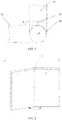
- The prior art provides a scheme to detect a folding angle by using a light emitter and a receiver. As shown in
FIG. 1 , a first foldablemain body 11, a second foldablemain body 12, alight emitter 13, and a plurality oflight receivers 14 arranged at intervals are used to determine a folding angle. The first foldablemain body 11 is rotationally connected to the second foldablemain body 12; thelight emitter 13 is fixed relative to the first foldablemain body 11; the plurality oflight receivers 14 are fixed relative to the second foldablemain body 12; thelight emitter 13 can be selectively matched with one of the plurality oflight receivers 14; and a processing unit is configured to: determine a target light receiver that is currently matched with the light emitter, and determine a folding angle of an electronic device with a foldable screen based on preset position information of the light receiver and the light emitter. - The existing light sensor-based scheme requires a great quantity of light receivers. However, because space of a rotating shaft is limited, a quantity of light receivers that can be disposed is limited. In addition, in a case that a great quantity of light receivers are used, costs are increased; and in a case that the great quantity of light receivers are disposed on a relatively small rotating shaft, difficulty in design is increased, and a great quantity of detection port resources of a central processing unit (Central Processing Unit, CPU) chip are occupied.
- In summary, an existing method for detecting a folding angle of an electronic device has the problems of high costs, great design difficulty, and high occupation of detection port resources.
- Embodiments of the present disclosure provides an electronic device, to resolve the problems of high costs, great design difficulty, and high occupation of detection port resources of a method for detecting a folding angle of an electronic device in the prior art.
- To resolve the foregoing problems, the embodiments of the present disclosure are implemented as follows:
- An embodiment of the present disclosure provides an electronic device, including:
- a first foldable main body;
- a second foldable main body, disposed on a side of the first foldable main body;
- a rotating shaft, disposed between the first foldable main body and the second foldable main body, wherein the first foldable main body and the second foldable main body are rotationally connected to each other by the rotating shaft; and
- a detection assembly, configured to detect a relative angle between the first foldable main body and the second foldable main body, where
- the detection assembly includes a first detection part and a second detection part, the first detection part is fixed relative to one of the first foldable main body and the second foldable main body, and the second detection part is fixed relative to the other one of the first foldable main body and the second foldable main body; and
- the second detection part includes a plurality of capacitors, where the plurality of capacitors are disposed at intervals in a rotating direction of the first foldable main body and the second foldable main body, capacitances of the capacitors are different from one another, the first detection part is switchably connected to the plurality of capacitors, and in a case that the first detection part is connected to one of the capacitors, the first detection part is conducted with the second detection part to form a detection loop.
- According to the technical solution of the present disclosure, a first detection part is fixed relative to one of two foldable main bodies; a second detection part is fixed relative to the other one of the two foldable main bodies; a detection loop is formed when the first detection part is switchably connected to a plurality of capacitors of the second detection part; and a relative angle between the first foldable main body and the second foldable main body is detected by the first detection part and the second detection part. Therefore, costs and space occupation can be reduced; and design difficulty can be decreased. In addition, detection for any angle can be realized, which improves detection performance.
-
-
FIG. 1 is a schematic diagram of applying a light emitter and a receiver according to the prior art; -
FIG. 2 is a schematic diagram of an electronic device according to an embodiment of the present disclosure; -
FIG. 3 is a schematic diagram of a detection assembly according to an embodiment of the present disclosure; -
FIG. 4 is a first schematic diagram of matching a rotating shaft with a circuit board according to an embodiment of the present disclosure; -
FIG. 5 is a second schematic diagram of matching a rotating shaft with a circuit board according to an embodiment of the present disclosure; -
FIG. 6a is a schematic diagram of connecting a capacitance reader with a controller and a first detection part according to an embodiment of the present disclosure; -
FIG. 6b is a schematic diagram of connecting a capacitance reader with a controller and a capacitor according to an embodiment of the present disclosure; -
FIG. 6c is a schematic diagram of disposing a capacitance reader and a controller on a foldable main body according to an embodiment of the present disclosure; and -
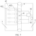
FIG. 7 is a schematic diagram of disposing a plurality of first detection parts on an electronic device according to an embodiment of the present disclosure. - The following clearly and completely describes the technical solutions in the embodiments of the present disclosure with reference to the accompanying drawings in the embodiments of the present disclosure. Apparently, the described embodiments are some but not all of the embodiments of the present disclosure. All other embodiments obtained by those of ordinary skill in the art based on the embodiments of the present disclosure without creative efforts shall fall within the protection scope of the present disclosure.
- An embodiment of the present disclosure provides an electronic device. As shown in
FIG. 2 andFIG. 3 , the electronic device includes: - a first foldable
main body 1; - a second foldable
main body 2, disposed on a side of the first foldablemain body 1; - a rotating
shaft 3, disposed between the first foldablemain body 1 and the second foldablemain body 2, wherein the first foldablemain body 1 and the second foldablemain body 2 are rotationally connected to each other by the rotatingshaft 3; and - a
detection assembly 4, configured to detect a relative angle between the first foldablemain body 1 and the second foldablemain body 2, where - the
detection assembly 4 includes afirst detection part 41 and asecond detection part 42, thefirst detection part 41 is fixed relative to one of the first foldablemain body 1 and the second foldablemain body 2, and thesecond detection part 42 is fixed relative to the other one of the first foldablemain body 1 and the second foldablemain body 2; and - the
second detection part 42 includes a plurality ofcapacitors 421, where the plurality ofcapacitors 421 are disposed at intervals in a rotating direction of the first foldablemain body 1 and the second foldablemain body 2, capacitances of thecapacitors 421 are different from one another, thefirst detection part 41 is switchably connected to the plurality ofcapacitors 421, and in a case that thefirst detection part 41 is connected to one of thecapacitors 421, thefirst detection part 41 is conducted with thesecond detection part 42 to form a detection loop. The detection loop includes a power supply. The power supply is separately connected to thefirst detection part 41 and thesecond detection part 42. The detection loop is formed when thefirst detection part 41 is in contact with thesecond detection part 42. - The electronic device in this embodiment of the present disclosure includes the first foldable
main body 1, the second foldablemain body 2 disposed on a side of the first foldablemain body 1, the rotatingshaft 3 disposed between the first foldablemain body 1 and the second foldablemain body 2, and thedetection assembly 4. - The electronic device may be a mobile phone, a tablet personal computer, a laptop computer, a personal digital assistant (PDA), a mobile Internet device (MID), a wearable device, or the like.
- The first foldable
main body 1 is rotationally connected to the second foldablemain body 2 by the rotatingshaft 3. The first foldablemain body 1 and the second foldablemain body 2 may not be particularly distinguished. As shown inFIG. 2 , a left foldable main body is the first foldable main body, and a right foldable main body is the second foldable main body; or the left foldable main body is the second foldable main body, and the right foldable main body is the first foldable main body. This embodiment of the present disclosure is described by using an example in which the left foldable main body is the first foldable main body and the right foldable main body is the second foldable main body. A case in which the left foldable main body is the second foldable main body and the right foldable main body is the first foldable main body is similar to the above case. Details are not described herein again. - The
detection assembly 4 includes afirst detection part 41 and asecond detection part 42. The two detection parts are disposed at different positions. For example, thefirst detection part 41 is fixed relative to the first foldablemain body 1, and thesecond detection part 42 is fixed relative to the second foldablemain body 2; or thefirst detection part 41 is fixed relative to the second foldablemain body 2, and thesecond detection part 42 is fixed relative to the first foldablemain body 1. - The
second detection part 42 includes a plurality ofcapacitors 421 that are disposed at intervals in a rotating direction of the first foldablemain body 1 and the second foldablemain body 2. When the first foldablemain body 1 rotates clockwise, the second foldablemain body 2 may rotate clockwise or counterclockwise. Distances between alladjacent capacitors 421 may be the same or different. All capacitances of thecapacitors 421 are different. Thecapacitors 421 may be pF-grade capacitors. - Owing to a position relationship between the
first detection part 41 and thesecond detection part 42 and rotational connection that is between the first foldablemain body 1 and the second foldablemain body 2 and that is implemented by therotating shaft 3, thefirst detection part 41 can be switchably connected to the plurality ofcapacitors 421. In a case that thefirst detection part 41 is connected to one of thecapacitors 421, thefirst detection part 41 is conducted with thesecond detection part 42 to form the detection loop. - After the detection loop is formed, the relative angle between the first foldable
main body 1 and the second foldablemain body 2 can be detected by thedetection assembly 4. Eachcapacitor 421 may correspond to a folding angle between the first foldablemain body 1 and the second foldablemain body 2. When thefirst detection part 41 is conducted with thesecond detection part 42, the relative angle between the first foldablemain body 1 and the second foldablemain body 2 can be determined based on acapacitor 421 that is connected to thefirst detection part 41. - According to the above structure, a first detection part is fixed relative to one of two foldable main bodies; a second detection part is fixed relative to the other one of the two foldable main bodies; and a detection loop for detecting the relative angle between the first foldable main body and the second foldable main body is formed when the first detection part is switchably connected to a plurality of capacitors of the second detection part. Therefore, costs and space occupation can be reduced; and design difficulty can be decreased. In addition, detection for any angle can be realized, which improves detection performance.
- In an embodiment of the present disclosure, as shown in
FIG. 2 andFIG. 3 , the first foldablemain body 1 is fixed relative to therotating shaft 3, the second foldablemain body 2 is rotationally mounted on therotating shaft 3, thefirst detection part 41 is mounted on the first foldablemain body 1 or therotating shaft 3, and thesecond detection part 42 is fixedly connected to the second foldablemain body 2. - The first foldable
main body 1 may be fixed relative to and connected to therotating shaft 3, and the second foldablemain body 2 is rotationally mounted on therotating shaft 3. Because the first foldablemain body 1 is fixed relative to therotating shaft 3, the second foldablemain body 2 can rotate relative to the first foldablemain body 1. In this case, a form of a structure in which thefirst detection part 41 is fixed relative to one of the two foldable main bodies, and thesecond detection part 42 is fixed relative to the other one of the two foldable main bodies is as follows: Thefirst detection part 41 is mounted on the first foldablemain body 1, and thesecond detection part 42 is fixedly connected to the second foldablemain body 2; or thefirst detection part 41 is mounted on therotating shaft 3, and thesecond detection part 42 is fixedly connected to the second foldablemain body 2. - For a case in which the
first detection part 41 is mounted on the first foldablemain body 1, thefirst detection part 41 may be disposed on an end surface, connected to therotating shaft 3, of the first foldablemain body 1, or disposed in the first foldablemain body 1, provided that thefirst detection part 41 can protrude from the first foldablemain body 1 and be connected to thesecond detection part 42. Accordingly, for a case in which thefirst detection part 41 is mounted on therotating shaft 3, in a case that thefirst detection part 41 is an elastic component, thefirst detection part 41 may be disposed at any position of therotating shaft 3, thereby being connected to thesecond detection part 42. - For a case in which the
second detection part 42 is fixedly connected to the second foldablemain body 2, the plurality ofcapacitors 421 included by thesecond detection part 42 may be disposed on an end surface, in contact with therotating shaft 3, of thesecond detection part 42. Alternatively, a cylinder sleeving therotating shaft 3 is disposed in the second foldablemain body 2, the plurality ofcapacitors 421 are disposed in a circumferential direction of the cylinder, such that thefirst detection part 41 can be switchably connected to the plurality ofcapacitors 421 in a rotating process of the second foldablemain body 2. - It should be noted that the distances between all the
adjacent capacitors 421 may be the same or different. Capacitances of all thecapacitors 421 are different. In a case that the distances between all theadjacent capacitors 421 are the same, capacitances between all theadjacent capacitors 421 may increase or decrease at a preset gradient. - In the above structure, the first foldable main body is fixed relative to the rotating shaft; the second foldable main body can rotate related to the rotating shaft; and the first detection part disposed on the first foldable main body or the rotating shaft can be switchably connected to the plurality of capacitors by rotating the second foldable main body. Therefore, the detection loop can be formed to detect the relative angle between the two foldable main bodies.
- As shown in
FIG. 2 to FIG. 5 , in a case in which thesecond detection part 42 is fixedly connected to the second foldablemain body 2, the electronic device further includes acircuit board 5. A through hole is formed in thecircuit board 5, therotating shaft 3 penetrates the through hole, the plurality ofcapacitors 421 are disposed on thecircuit board 5 at intervals in the circumferential direction of therotating shaft 3, thecircuit board 5 is fixed relative to the second foldablemain body 2, and thefirst detection part 41 is fixed relative to the first foldablemain body 1. - In this embodiment, the electronic device further includes the
circuit board 5. Thecircuit board 5 may be a printed circuit board (PCB). A through hole may be formed in thecircuit board 5. Therotating shaft 3 is connected to thecircuit board 5 by penetrating the through hole. Thecapacitors 421 may be disposed on thecircuit board 5 at intervals in the circumferential direction of therotating shaft 3. Because thecircuit board 5 is fixed relative to the second foldablemain body 2, rotation of the second foldablemain body 2 can drive thecircuit board 5 to rotate. Thefirst detection part 41 can be switchably connected to the plurality ofcapacitors 421 in a rotating process of thecircuit board 5, where thefirst detection part 41 is fixed relative to the first foldablemain body 1. Because the first foldablemain body 1 is fixed relative to therotating shaft 3, thefirst detection part 41 may be disposed on the first foldablemain body 1 or therotating shaft 3. - The
circuit board 5 may be circular or of other shapes. The through hole is formed in a central position or other positions of the circuit board. When the circuit board is connected to therotating shaft 3, therotating shaft 3 may penetrate the through hole in the circuit board, thereby mounting the circuit board on therotating shaft 3. - An angle corresponding to each
capacitor 421 may be determined according to a layout of the plurality ofcapacitors 421, such that when thefirst detection part 41 is in contact with thecapacitor 421, a corresponding angle between the two foldable main bodies can be determined. In this embodiment, the plurality ofcapacitors 421 are disposed on thecircuit board 5 at intervals in the circumferential direction of therotating shaft 3. Optionally, the plurality ofcapacitors 421 may be disposed around therotating shaft 3 by one circle. For a case in which eachcapacitor 421 may correspond to one angle, in a process of rotating the second foldablemain body 2 relative to therotating shaft 3, thefirst detection part 41 can be switchably connected to the plurality ofcapacitors 421. The detection loop can be formed when thefirst detection part 41 is connected to thecapacitor 421. Therefore, the angle between the two foldable main bodies can be detected. - When the
capacitors 421 are disposed at intervals in the circumferential direction of therotating shaft 3, a circumference corresponding to therotating shaft 3 may be divided into equal parts or different arcs. For a case in which the circumference corresponding to therotating shaft 3 is divided into different arcs, a length of each arc is required for determining an angle corresponding to eachcapacitor 421. For a case in which the circumference corresponding to therotating shaft 3 is divided into equal parts, arcs corresponding to all theadjacent capacitors 421 are equal. In this case, the capacitances of all theadjacent capacitors 421 may increase or decrease at a preset gradient. Accordingly, angles corresponding to all theadjacent capacitors 421 may increase or decrease by a preset angle difference, such that differences between the angles corresponding to all theadjacent capacitors 421 are equal. - The following uses a specific embodiment to describe the case in which the plurality of
capacitors 421 divide the circumference corresponding to therotating shaft 3 into equal parts. As shown inFIG. 2 to FIG. 5 , when the second foldablemain body 2 rotates around therotating shaft 3, thecircuit board 5 rotates around therotating shaft 3 by a same angle under the driving of the second foldablemain body 2, and thefirst detection part 41 is disposed on the first foldablemain body 1 or therotating shaft 3, and can be switchably connected to the plurality ofcapacitors 421 disposed on thecircuit board 5, thereby determining the angle between the two foldable main bodies. When a quantity of thecapacitors 421 is N, and theN capacitors 421 are sequentially disposed at intervals on a 360° circumference, a corresponding relation between thecapacitors 421 and angles can be established. For example, when N is 10, the quantity of thecapacitors 421 is 10, and an angle corresponding to thecapacitor 421 is (360/N)*(a-1), where a is a number in the 10capacitors 421. For details, refer to the following table:Capacitance Capacitor number Angle 0 1 0 10 2 36 20 3 72 30 4 108 40 5 144 50 6 180 60 7 216 70 8 252 80 9 288 90 10 324 - For example, the following can be learned according to the corresponding relation in the table: When it is detected that a capacitance of the
capacitor 421 is 10, it can be determined according to the corresponding relation that a corresponding number is 2, and that a corresponding folding angle is 36°. Details about other cases are not described herein again. - It should be noted that, a number and a corresponding angle of a capacitor may be determined in the following process: First, determine, as 1, a number of a capacitor corresponding to 0° on the circumference corresponding to the rotating shaft; then, determine lengths of arcs between the capacitor and the other capacitors; obtain central angles corresponding to the lengths of the arcs; determine the central angles as angles corresponding to the other capacitors; and sequentially determine capacitor numbers in ascending order of the angles, where the capacitor numbers are positively correlated with the angles, and capacitances of the capacitors are positively correlated with the capacitor numbers.
- For a case in which the plurality of
capacitors 421 divide the circumference corresponding to therotating shaft 3 into different arcs, the lengths of the arcs betweenadjacent capacitors 421 may increase sequentially. In this case, differences between angles corresponding to theadjacent capacitors 421 increase sequentially. In this case, thecapacitors 421 may also be numbered one by one. To facilitate memorization, it may be specified that the capacitances of thecapacitors 421 sequentially increase or decrease in an extending direction of the arcs; or a corresponding relation between the capacitances of thecapacitors 421 and numbers is established, for example, acapacitor 421 whose capacitance is greater has a greater number. In a case that thecapacitor 421 is in contact with thefirst detection part 41, a number is determined based on an obtained capacitance. Then, the angle between the two foldable main bodies is determined. - In the above structure, the circuit board is disposed on the rotating shaft, and the plurality of capacitors are disposed on the circuit board in the circumferential direction of the rotating shaft, and are driven to rotate when the second foldable main body rotates around the rotating shaft, such that the first detection part can be switchably connected to the plurality of capacitors. Therefore, the detection loop can be formed to detect the relative angle between the two foldable main bodies.
- Optionally, in an embodiment of the present disclosure, as shown in
FIG. 2 andFIG. 3 , the first foldablemain body 1 can rotate relative to therotating shaft 3, the second foldablemain body 2 can rotate relative to therotating shaft 3, thefirst detection part 41 is mounted on the first foldablemain body 1, and thesecond detection part 42 is fixedly connected to the second foldablemain body 2. - In this embodiment, both the first foldable
main body 1 and the second foldablemain body 2 can rotate relative to therotating shaft 3. In this case, thefirst detection part 41 is mounted on the first foldablemain body 1, and thesecond detection part 42 is fixedly connected to the second foldablemain body 2. - In a process in which only the first foldable
main body 1 rotates relative to therotating shaft 3, thefirst detection part 41 disposed on the first foldablemain body 1 rotates with the first foldablemain body 1, and is switchably connected to the plurality ofcapacitors 421 disposed on the second foldablemain body 2 in sequence. Therefore, the detection loop can be formed to detect the relative angle between the two foldable main bodies. - In a process in which only the second foldable
main body 2 rotates relative to therotating shaft 3, the plurality ofcapacitors 421 disposed on the second foldablemain body 2 rotate with the second foldablemain body 2, thefirst detection part 41 disposed on the first foldablemain body 1 is kept stationary, the plurality ofcapacitors 421 are sequentially connected to thefirst detection part 41. Therefore, the detection loop can be formed to detect the relative angle between the two foldable main bodies. - In a process in which both the first foldable
main body 1 and the second foldablemain body 2 rotate relative to therotating shaft 3, the plurality ofcapacitors 421 disposed on the second foldablemain body 2 rotate with the second foldablemain body 2, thefirst detection part 41 disposed on the first foldablemain body 1 rotates with the first foldablemain body 1, thefirst detection part 41 is switchably connected to the plurality ofcapacitors 421 in sequence. Therefore, the detection loop can be formed to detect the relative angle between the two foldable main bodies. - Each
capacitor 421 may correspond to a folding angle between the first foldablemain body 1 and the second foldablemain body 2. When thefirst detection part 41 is conducted with thesecond detection part 42, the relative angle between the first foldablemain body 1 and the second foldablemain body 2 can be determined based on acapacitor 421 that is connected to thefirst detection part 41. - In the above structure, it is specified that the first foldable main body and the second foldable main body rotate relative to the rotating shaft; and the first detection part is switchably connected to the plurality of capacitors by rotating the second foldable main body and/or the first foldable main body. Therefore, the detection loop can be formed to detect the relative angle between the two foldable main bodies.
- Optionally, in an embodiment of the present disclosure, as shown in
FIG. 2 to FIG. 5 , thefirst detection part 41 includes aconductive spring plate 411, theconductive spring plate 411 is provided with a protruding part, and the protruding part is switchably connected to the plurality ofcapacitors 421. - In this embodiment, the
first detection part 41 includes theconductive spring plate 411 that is provided with the protruding part; and theconductive spring plate 411 is switchably connected to the plurality ofcapacitors 421 through the protruding part. For example, the first foldablemain body 1 is rotationally connected to the second foldablemain body 2 by therotating shaft 3; thefirst detection part 41 is fixed relative to one of the two foldable main bodies; and the plurality ofcapacitors 421 are fixed relative to the other one of the two foldable main bodies. Therefore, theconductive spring plate 411 can be switchably connected to the plurality ofcapacitors 421 in sequence through the protruding part. - The conductive spring plate provided with the protruding part can be conveniently connected to the capacitor when the conductive spring plate is disposed at any position. Therefore, the position of the conductive spring plate is diversified.
- The
second detection part 42 further includes a plurality ofconductive parts 422, each of theconductive parts 422 is connected to one of thecapacitors 421, and in a case that the protruding part is connected to one of theconductive parts 422, theconductive spring plate 411, theconductive part 422, and thecapacitor 421 are conducted with one another to form the detection loop. - The
second detection part 42 includes the plurality ofcapacitors 421 and the plurality ofconductive parts 422. Eachconductive part 422 may include a copper-exposed region. A quantity of thecapacitors 421 is the same as a quantity of theconductive parts 422. Eachcapacitor 421 is correspondingly connected to oneconductive part 422. When thefirst detection part 41 is switchably connected to the plurality ofcapacitors 421 to form the detection loop, the protruding part of theconductive spring plate 411 is connected to oneconductive part 422. Specifically, the protruding part is connected to the copper-exposed region of theconductive part 422. Because theconductive part 422 is correspondingly connected to onecapacitor 421, theconductive spring plate 411 can be connected to thecapacitor 421. Therefore, theconductive spring plate 411, theconductive part 422, and thecapacitor 421 form the detection loop. This enables theconductive spring plate 411 to be switchably connected to the plurality ofcapacitors 421 in sequence. - The
conductive spring plate 411 may be a metal spring plate. Optionally, theconductive spring plate 411 is an antenna spring plate. Connection between theconductive spring plate 411 and theconductive part 422 is implemented via contact between the metal spring plate and the copper-exposed region. - In the above structure, the conductive spring plate, the conductive part, and the capacitor are conducted to form the detection loop. Therefore, in a case that the conductive spring plate is in contact with the conductive part, the conductive spring plate can be switchably connected to the plurality of capacitors in sequence.
- Optionally, in an embodiment of the present disclosure, as shown in
FIG. 3 , eachcapacitor 421 is grounded. Forming of the detection loop can be guaranteed by setting thecapacitor 421 to be grounded. - Optionally, in an embodiment of the present disclosure, as shown in
FIG. 2 ,FIG. 3 , andFIG. 6a toFIG. 6c , the detection loop further includes acapacitance reader 61 and acontroller 62 connected to thecapacitance reader 61. Thecapacitance reader 61 obtains a current capacitance of one of thecapacitors 421 that is connected to thefirst detection part 41, and thecontroller 62 stores a target capacitance and obtains the relative angle between the first foldablemain body 1 and the second foldablemain body 2 based on the current capacitance and the target capacitance. - In addition to the
first detection part 41 and thesecond detection part 42, the detection loop further includes thecapacitance reader 61 and thecontroller 62. Thecapacitance reader 61 and thecontroller 62 may be disposed on the first foldablemain body 1, the second foldablemain body 2, or therotating shaft 3. Thecapacitance reader 61 may be connected to thefirst detection part 41, and be configured to read, in a case that thefirst detection part 41 is connected to one of thecapacitors 421, a capacitance of thecurrent capacitor 421 connected to thefirst detection part 41. Thecapacitance reader 61 may also be connected to eachcapacitor 421, and be configured to read a capacitance of thecurrent capacitor 421 when thecapacitor 421 is connected to thefirst detection part 41. - The
capacitance reader 61 may also be replaced with a voltage capacitance reader. The voltage capacitance reader reads a voltage corresponding to thecapacitor 421, to determine the capacitance of thecapacitor 421. Then, the relative angle between the first foldablemain body 1 and the second foldablemain body 2 is obtained. - After obtaining the capacitance of the
current capacitor 421 connected to thefirst detection part 41, thecapacitance reader 61 may send the current capacitance corresponding to thecurrent capacitor 421 to thecontroller 62. Thecontroller 62 stores the target capacitance, and can obtain the relative angle between the first foldablemain body 1 and the second foldablemain body 2 based on the current capacitance corresponding to thecurrent capacitor 421 and the target capacitance. - The relative angle between the first foldable
main body 1 and the second foldablemain body 2 can be determined based on the current capacitance corresponding to thecurrent capacitor 421 and the target capacitance in the following process: Compare the current capacitance with the target capacitance; and in a case that the current capacitance is successfully matched with the target capacitance, determine a relative angle corresponding to the target capacitance as the relative angle that is between the first foldablemain body 1 and the second foldablemain body 2 and that corresponds to thecurrent capacitor 421. - As shown in
FIG. 2 ,FIG. 3 ,FIG. 4 , andFIG. 6a toFIG. 6c , the plurality ofcapacitors 421 are uniformly disposed at intervals, there are a plurality of target capacitances that are in a one-to-one correspondence with the plurality ofcapacitors 421, and each of the target capacitances corresponds to one relative angle between the first foldablemain body 1 and the second foldablemain body 2. - As the plurality of
capacitors 421 are uniformly disposed at intervals, distances between alladjacent capacitors 421 are the same. In this case, it may be specified that differences between all theadjacent capacitors 421 are the same, such that the capacitances of the plurality ofcapacitors 421 increase sequentially in a specific direction. - A quantity of the target capacitances is equal to the quantity of the
capacitors 421, and the target capacitances are in a one-to-one correspondence with the plurality ofcapacitors 421. In a case that thefirst detection part 41 is connected to one of thecapacitors 421, the current capacitance obtained by thecapacitance reader 61 is compared with the target capacitance corresponding to thecurrent capacitor 421. In a case that the current capacitance is consistent with the target capacitance, a relative angle corresponding to the target capacitance is determined as the relative angle that is between the two foldable main bodies and that corresponds to thecurrent capacitor 421. - In the above structure, in a case that the capacitance of the current capacitor is determined, a relative angle corresponding to the current capacitor is determined based on the relative angle corresponding to the target capacitance.
- It should be noted that all the above embodiments are cases implemented in a case that only one first detection part is disposed. Those skilled in the art may also dispose a plurality of first detection parts. In addition, the plurality of first detection parts are disposed in a one-to-one correspondence with the plurality of capacitors; and one first detection part and one capacitor form one detection loop. As shown in
FIG. 7 , thesecond detection part 42 including the plurality ofcapacitors 421 and the plurality ofconductive parts 422 is disposed on the first foldablemain body 1; and the plurality offirst detection parts 41 are disposed on therotating shaft 3, extend along an axis of therotating shaft 3, and are arranged sequentially in the circumferential direction of therotating shaft 3. The first foldablemain body 1 can rotate relative to therotating shaft 3. In this case, therotating shaft 3 is fixed relative to the second foldablemain body 2. When the first foldablemain body 1 rotates relative to therotating shaft 3, the plurality ofconductive parts 422 disposed on the first foldablemain body 1 are sequentially conducted with the plurality offirst detection parts 41 disposed on therotating shaft 3, such that thefirst detection parts 41, theconductive parts 422, and thecapacitors 421 are conducted to form the detection loop, where each time of conduction corresponds to a unique detection loop. Each detection loop corresponds to a uniquefirst detection part 41, a uniqueconductive part 422, and aunique capacitor 421. Eachfirst detection part 41 may be connected to thecapacitance reader 61, such that thecapacitance reader 61 obtains the current capacitance of thecurrent capacitor 421 connected to thefirst detection part 41. Thecapacitance reader 61 may be connected to thecontroller 62, such that thecontroller 62 obtains the relative angle between the first foldablemain body 1 and the second foldablemain body 2 based on the current capacitance and the target capacitance. Certainly, the plurality of first detection parts may also be disposed in another structure. For example, both the first foldable main body and the second foldable main body can rotate relative to the rotating shaft; the second detection part is disposed on the first foldable main body; and the plurality of first detection parts are disposed on the second foldable main body. There may also be other structural forms which are not enumerated herein. - According to the above embodiments of the electronic device in the present disclosure, a first detection part is fixed relative to one of two foldable main bodies; a second detection part is fixed relative to the other one of the two foldable main bodies; a detection loop is formed when the first detection part is switchably connected to a plurality of capacitors of the second detection part; and a relative angle between the first foldable main body and the second foldable main body is detected by the first detection part and the second detection part. Therefore, costs and space occupation can be reduced; and design difficulty can be decreased. In addition, detection for any angle can be realized, which improves detection performance.
- Each embodiment in this specification is described in a progressive manner, each embodiment focuses on the difference from other embodiments, and the same and similar parts between the embodiments may refer to each other.
- Although optional embodiments of the present disclosure have been described, those skilled in the art may make additional changes and modifications to these embodiments once they learn the basic inventive concept. Therefore, the appended claims are intended to be construed as covering the optional embodiments and all changes and modifications falling within the scope of the embodiments of the present disclosure.
- Finally, it should be further noted that, in this specification, relationship terms such as first and second are only used to distinguish an entity or operation from another entity or operation, but do not necessarily require or imply that there is any actual relationship or order between these entities or operations. Moreover, the terms "include", "comprise", or any of their variants are intended to cover a non-exclusive inclusion, so that a process, a method, an article, or a terminal device that includes a list of elements not only includes those elements but also includes other elements that are not listed, or further includes elements inherent to such a process, method, article, or terminal device. Without being subject to further limitations, an element defined by a phrase "including a......" does not exclude presence of other identical elements in the process, method, article, or terminal device that includes the very element.
- The embodiments of the present disclosure are described above with reference to the accompanying drawings, but the present disclosure is not limited to the foregoing specific implementation manners, and the foregoing specific implementation manners are only illustrative and not restrictive. Under the enlightenment of the present disclosure, a person of ordinary skill in the art can make many forms without departing from the purpose of the present disclosure and the protection scope of the claims, and all of these fall within the protection of the present disclosure.
Claims (9)
- An electronic device, comprising:a first foldable main body;a second foldable main body, disposed on a side of the first foldable main body;a rotating shaft, disposed between the first foldable main body and the second foldable main body, wherein the first foldable main body and the second foldable main body are rotationally connected to each other by the rotating shaft; anda detection assembly, configured to detect a relative angle between the first foldable main body and the second foldable main body, whereinthe detection assembly comprises a first detection part and a second detection part, the first detection part is fixed relative to one of the first foldable main body and the second foldable main body, and the second detection part is fixed relative to the other one of the first foldable main body and the second foldable main body; andthe second detection part comprises a plurality of capacitors, wherein the capacitors are disposed at intervals in a rotating direction of the first foldable main body and the second foldable main body, capacitances of the capacitors are different from one another, the first detection part is switchably connected to the capacitors, and in a case that the first detection part is connected to one of the capacitors, the first detection part is conducted with the second detection part to form a detection loop.
- The electronic device according to claim 1, wherein the first foldable main body is fixed relative to the rotating shaft, the second foldable main body is rotationally mounted on the rotating shaft, the first detection part is mounted on the first foldable main body or the rotating shaft, and the second detection part is fixedly connected to the second foldable main body.
- The electronic device according to claim 2, further comprising:
a circuit board, wherein a through hole is formed in the circuit board, the rotating shaft penetrates the through hole, the capacitors are disposed on the circuit board at intervals in a circumferential direction of the rotating shaft, the circuit board is fixed relative to the second foldable main body, and the first detection part is fixed relative to the first foldable main body. - The electronic device according to claim 1, wherein the first foldable main body can rotate relative to the rotating shaft, the second foldable main body can rotate relative to the rotating shaft, the first detection part is mounted on the first foldable main body, and the second detection part is fixedly connected to the second foldable main body.
- The electronic device according to claim 1, wherein the first detection part comprises a conductive spring plate, the conductive spring plate is provided with a protruding part, and the protruding part is switchably connected to the capacitors.
- The electronic device according to claim 5, wherein the second detection part further comprises a plurality of conductive parts, each of the conductive parts is connected to one of the capacitors, and in a case that the protruding part is connected to one of the conductive parts, the conductive spring plate, the conductive part, and the capacitor are conducted with one another to form the detection loop.
- The electronic device according to claim 1, wherein each capacitor is grounded.
- The electronic device according to claim 1, wherein the detection loop further comprises a capacitance reader and a controller connected to the capacitance reader, the capacitance reader obtains a current capacitance of one of the capacitors that is connected to the first detection part, and the controller stores a target capacitance and obtains the relative angle between the first foldable main body and the second foldable main body based on the current capacitance and the target capacitance.
- The electronic device according to claim 8, wherein the capacitors are uniformly disposed at intervals, there are a plurality of target capacitances that are in a one-to-one correspondence with the plurality of capacitors, and each of the target capacitances corresponds to one relative angle between the first foldable main body and the second foldable main body.
Applications Claiming Priority (2)
| Application Number | Priority Date | Filing Date | Title |
|---|---|---|---|
| CN202010354342.9A CN111562812B (en) | 2020-04-29 | 2020-04-29 | Electronic device |
| PCT/CN2021/088821 WO2021218749A1 (en) | 2020-04-29 | 2021-04-22 | Electronic device |
Publications (3)
| Publication Number | Publication Date |
|---|---|
| EP4145244A1 true EP4145244A1 (en) | 2023-03-08 |
| EP4145244A4 EP4145244A4 (en) | 2023-11-01 |
| EP4145244B1 EP4145244B1 (en) | 2025-06-18 |
Family
ID=72074442
Family Applications (1)
| Application Number | Title | Priority Date | Filing Date |
|---|---|---|---|
| EP21795700.0A Active EP4145244B1 (en) | 2020-04-29 | 2021-04-22 | Electronic device |
Country Status (5)
| Country | Link |
|---|---|
| US (1) | US12222762B2 (en) |
| EP (1) | EP4145244B1 (en) |
| CN (1) | CN111562812B (en) |
| ES (1) | ES3035998T3 (en) |
| WO (1) | WO2021218749A1 (en) |
Families Citing this family (3)
| Publication number | Priority date | Publication date | Assignee | Title |
|---|---|---|---|---|
| CN111562812B (en) * | 2020-04-29 | 2022-03-11 | 维沃移动通信有限公司 | Electronic device |
| WO2023015435A1 (en) * | 2021-08-10 | 2023-02-16 | 京东方科技集团股份有限公司 | Foldable display apparatus and driving method therefor |
| CN114876945B (en) * | 2022-05-16 | 2023-02-28 | 维沃移动通信有限公司 | Electronic equipment |
Family Cites Families (23)
| Publication number | Priority date | Publication date | Assignee | Title |
|---|---|---|---|---|
| US5936613A (en) * | 1993-11-05 | 1999-08-10 | Intertactile Technologies Corporation | Rotary circuit control devices with changeable graphics |
| GB9815826D0 (en) * | 1998-07-22 | 1998-09-16 | British Aerospace | Capacitive position transducer |
| US6492911B1 (en) * | 1999-04-19 | 2002-12-10 | Netzer Motion Sensors Ltd. | Capacitive displacement encoder |
| GB2418493B (en) * | 2003-08-21 | 2006-11-15 | Harald Philipp | Capacitive position sensor |
| KR101003752B1 (en) * | 2007-04-24 | 2010-12-23 | 에이디반도체(주) | Slide cell phone to determine whether it is opened or closed through the capacitive sensor |
| JP4189433B1 (en) * | 2007-10-18 | 2008-12-03 | パナソニック株式会社 | Portable radio |
| CN101470469A (en) * | 2007-12-25 | 2009-07-01 | 诺伯·古斯奇 | Folding computer |
| US9195332B2 (en) * | 2013-05-23 | 2015-11-24 | Nokia Technologies Oy | Apparatus with deformable flexible user interface area and adjustable hover input region and associated methods |
| CN106152933B (en) * | 2015-04-09 | 2019-01-15 | 联想(北京)有限公司 | A kind of detection device, method and electronic equipment |
| US10551798B1 (en) * | 2016-05-17 | 2020-02-04 | Apple Inc. | Rotatable crown for an electronic device |
| US10558277B2 (en) * | 2016-08-04 | 2020-02-11 | Microsoft Technology Licensing, Llc | Folding angle sensing of a foldable device |
| CN106438669B (en) * | 2016-09-18 | 2020-01-21 | 合肥联宝信息技术有限公司 | Rotating shaft assembly, electronic equipment and method for detecting opening angle of electronic equipment |
| CN107168629A (en) * | 2017-03-22 | 2017-09-15 | 捷开通讯(深圳)有限公司 | A kind of control method, control system and the equipment of flexible screen equipment |
| CN107144216B (en) * | 2017-04-28 | 2019-11-26 | 维沃移动通信有限公司 | A kind of detection method and mobile terminal of angle value |
| US20190064950A1 (en) * | 2017-08-24 | 2019-02-28 | Int Tech Co., Ltd. | Foldable electronic device and control method thereof |
| CN108364574B (en) * | 2018-01-19 | 2020-06-02 | 云谷(固安)科技有限公司 | Folding display device and method for determining folding angle of display device |
| CN108845621B (en) * | 2018-06-22 | 2021-06-15 | 联想(北京)有限公司 | Electronic device and information processing method |
| CN110716611A (en) * | 2018-07-13 | 2020-01-21 | 中兴通讯股份有限公司 | Folding angle determination method, device, folding terminal and computer storage medium |
| CN208548267U (en) * | 2018-08-16 | 2019-02-26 | 深圳市金联信科技有限公司 | A kind of regulation device and capacitor manufacturing system |
| CN109040377B (en) * | 2018-09-20 | 2020-06-30 | 维沃移动通信有限公司 | An angle determination circuit, method and folding screen terminal |
| CN110417961B (en) * | 2019-07-17 | 2021-03-12 | Oppo广东移动通信有限公司 | Folding screen electronic device and method for determining folding angle |
| CN110719351B (en) * | 2019-09-30 | 2021-05-28 | 维沃移动通信有限公司 | A method and electronic device for determining the boundary point of a folding screen |
| CN111562812B (en) * | 2020-04-29 | 2022-03-11 | 维沃移动通信有限公司 | Electronic device |
-
2020
- 2020-04-29 CN CN202010354342.9A patent/CN111562812B/en active Active
-
2021
- 2021-04-22 EP EP21795700.0A patent/EP4145244B1/en active Active
- 2021-04-22 WO PCT/CN2021/088821 patent/WO2021218749A1/en not_active Ceased
- 2021-04-22 ES ES21795700T patent/ES3035998T3/en active Active
-
2022
- 2022-10-26 US US17/974,512 patent/US12222762B2/en active Active
Also Published As
| Publication number | Publication date |
|---|---|
| WO2021218749A1 (en) | 2021-11-04 |
| US20230046687A1 (en) | 2023-02-16 |
| EP4145244A4 (en) | 2023-11-01 |
| US12222762B2 (en) | 2025-02-11 |
| CN111562812A (en) | 2020-08-21 |
| ES3035998T3 (en) | 2025-09-11 |
| CN111562812B (en) | 2022-03-11 |
| EP4145244B1 (en) | 2025-06-18 |
Similar Documents
| Publication | Publication Date | Title |
|---|---|---|
| US12222762B2 (en) | Electronic device | |
| US10483057B2 (en) | Input device | |
| US10088934B2 (en) | Array substrate and display panel | |
| JP4646340B2 (en) | Input device | |
| EP1523750B1 (en) | Keypad device | |
| US20060066585A1 (en) | Apparatus for induced capacitor | |
| JP2003223275A (en) | Input device | |
| US3729728A (en) | Capacitive switching device | |
| US5657006A (en) | Capacitance type rotation angle sensor | |
| US11803257B2 (en) | Input support device and input detection system | |
| US20080278907A1 (en) | Fastening apparatus | |
| US5223797A (en) | Rotatable capacitance sensor | |
| US12034223B2 (en) | Mobile device with communication and sensing functions | |
| US7391465B2 (en) | Electronic device with rotatable image capture device | |
| US10649499B1 (en) | Electronic device and detachable base | |
| CN107172555A (en) | Rotation detection device, control device, separate type call bracelet and its control method | |
| CN109540178B (en) | Counting structure for judging position of character wheel based on capacitance | |
| CN100431070C (en) | Variable capacitor | |
| CN217957175U (en) | Electronic equipment with cameras arranged | |
| US11171403B1 (en) | Auto orientating antenna device | |
| CN116153238A (en) | Display device and driving method thereof | |
| JP3170072B2 (en) | Coordinate input device | |
| JP2018190580A (en) | Proximity sensor | |
| CN106654570B (en) | Antenna device for mobile terminal and mobile terminal | |
| CN116839467A (en) | Angle detection device, detection equipment and electronic equipment |
Legal Events
| Date | Code | Title | Description |
|---|---|---|---|
| STAA | Information on the status of an ep patent application or granted ep patent |
Free format text: STATUS: THE INTERNATIONAL PUBLICATION HAS BEEN MADE |
|
| PUAI | Public reference made under article 153(3) epc to a published international application that has entered the european phase |
Free format text: ORIGINAL CODE: 0009012 |
|
| STAA | Information on the status of an ep patent application or granted ep patent |
Free format text: STATUS: REQUEST FOR EXAMINATION WAS MADE |
|
| 17P | Request for examination filed |
Effective date: 20221124 |
|
| AK | Designated contracting states |
Kind code of ref document: A1 Designated state(s): AL AT BE BG CH CY CZ DE DK EE ES FI FR GB GR HR HU IE IS IT LI LT LU LV MC MK MT NL NO PL PT RO RS SE SI SK SM TR |
|
| DAV | Request for validation of the european patent (deleted) | ||
| DAX | Request for extension of the european patent (deleted) | ||
| A4 | Supplementary search report drawn up and despatched |
Effective date: 20230928 |
|
| RIC1 | Information provided on ipc code assigned before grant |
Ipc: G06F 1/16 20060101AFI20230922BHEP |
|
| GRAP | Despatch of communication of intention to grant a patent |
Free format text: ORIGINAL CODE: EPIDOSNIGR1 |
|
| STAA | Information on the status of an ep patent application or granted ep patent |
Free format text: STATUS: GRANT OF PATENT IS INTENDED |
|
| GRAS | Grant fee paid |
Free format text: ORIGINAL CODE: EPIDOSNIGR3 |
|
| GRAA | (expected) grant |
Free format text: ORIGINAL CODE: 0009210 |
|
| STAA | Information on the status of an ep patent application or granted ep patent |
Free format text: STATUS: THE PATENT HAS BEEN GRANTED |
|
| INTG | Intention to grant announced |
Effective date: 20250422 |
|
| AK | Designated contracting states |
Kind code of ref document: B1 Designated state(s): AL AT BE BG CH CY CZ DE DK EE ES FI FR GB GR HR HU IE IS IT LI LT LU LV MC MK MT NL NO PL PT RO RS SE SI SK SM TR |
|
| REG | Reference to a national code |
Ref country code: GB Ref legal event code: FG4D |
|
| REG | Reference to a national code |
Ref country code: CH Ref legal event code: EP |
|
| REG | Reference to a national code |
Ref country code: DE Ref legal event code: R096 Ref document number: 602021032531 Country of ref document: DE |
|
| REG | Reference to a national code |
Ref country code: CH Ref legal event code: EP |
|
| REG | Reference to a national code |
Ref country code: IE Ref legal event code: FG4D |
|
| REG | Reference to a national code |
Ref country code: NL Ref legal event code: FP |
|
| REG | Reference to a national code |
Ref country code: ES Ref legal event code: FG2A Ref document number: 3035998 Country of ref document: ES Kind code of ref document: T3 Effective date: 20250911 |
|
| PG25 | Lapsed in a contracting state [announced via postgrant information from national office to epo] |
Ref country code: FI Free format text: LAPSE BECAUSE OF FAILURE TO SUBMIT A TRANSLATION OF THE DESCRIPTION OR TO PAY THE FEE WITHIN THE PRESCRIBED TIME-LIMIT Effective date: 20250618 |
|
| REG | Reference to a national code |
Ref country code: LT Ref legal event code: MG9D |
|
| PG25 | Lapsed in a contracting state [announced via postgrant information from national office to epo] |
Ref country code: GR Free format text: LAPSE BECAUSE OF FAILURE TO SUBMIT A TRANSLATION OF THE DESCRIPTION OR TO PAY THE FEE WITHIN THE PRESCRIBED TIME-LIMIT Effective date: 20250919 Ref country code: NO Free format text: LAPSE BECAUSE OF FAILURE TO SUBMIT A TRANSLATION OF THE DESCRIPTION OR TO PAY THE FEE WITHIN THE PRESCRIBED TIME-LIMIT Effective date: 20250918 |
|
| PG25 | Lapsed in a contracting state [announced via postgrant information from national office to epo] |
Ref country code: BG Free format text: LAPSE BECAUSE OF FAILURE TO SUBMIT A TRANSLATION OF THE DESCRIPTION OR TO PAY THE FEE WITHIN THE PRESCRIBED TIME-LIMIT Effective date: 20250618 |
|
| PG25 | Lapsed in a contracting state [announced via postgrant information from national office to epo] |
Ref country code: HR Free format text: LAPSE BECAUSE OF FAILURE TO SUBMIT A TRANSLATION OF THE DESCRIPTION OR TO PAY THE FEE WITHIN THE PRESCRIBED TIME-LIMIT Effective date: 20250618 |
|
| PG25 | Lapsed in a contracting state [announced via postgrant information from national office to epo] |
Ref country code: RS Free format text: LAPSE BECAUSE OF FAILURE TO SUBMIT A TRANSLATION OF THE DESCRIPTION OR TO PAY THE FEE WITHIN THE PRESCRIBED TIME-LIMIT Effective date: 20250918 |
|
| PG25 | Lapsed in a contracting state [announced via postgrant information from national office to epo] |
Ref country code: LV Free format text: LAPSE BECAUSE OF FAILURE TO SUBMIT A TRANSLATION OF THE DESCRIPTION OR TO PAY THE FEE WITHIN THE PRESCRIBED TIME-LIMIT Effective date: 20250618 |
|
| PG25 | Lapsed in a contracting state [announced via postgrant information from national office to epo] |
Ref country code: PT Free format text: LAPSE BECAUSE OF FAILURE TO SUBMIT A TRANSLATION OF THE DESCRIPTION OR TO PAY THE FEE WITHIN THE PRESCRIBED TIME-LIMIT Effective date: 20251020 |
|
| REG | Reference to a national code |
Ref country code: AT Ref legal event code: MK05 Ref document number: 1804789 Country of ref document: AT Kind code of ref document: T Effective date: 20250618 |
|
| PG25 | Lapsed in a contracting state [announced via postgrant information from national office to epo] |
Ref country code: IS Free format text: LAPSE BECAUSE OF FAILURE TO SUBMIT A TRANSLATION OF THE DESCRIPTION OR TO PAY THE FEE WITHIN THE PRESCRIBED TIME-LIMIT Effective date: 20251018 |
|
| PG25 | Lapsed in a contracting state [announced via postgrant information from national office to epo] |
Ref country code: AT Free format text: LAPSE BECAUSE OF FAILURE TO SUBMIT A TRANSLATION OF THE DESCRIPTION OR TO PAY THE FEE WITHIN THE PRESCRIBED TIME-LIMIT Effective date: 20250618 Ref country code: SM Free format text: LAPSE BECAUSE OF FAILURE TO SUBMIT A TRANSLATION OF THE DESCRIPTION OR TO PAY THE FEE WITHIN THE PRESCRIBED TIME-LIMIT Effective date: 20250618 |
|
| PG25 | Lapsed in a contracting state [announced via postgrant information from national office to epo] |
Ref country code: CZ Free format text: LAPSE BECAUSE OF FAILURE TO SUBMIT A TRANSLATION OF THE DESCRIPTION OR TO PAY THE FEE WITHIN THE PRESCRIBED TIME-LIMIT Effective date: 20250618 |
|
| PG25 | Lapsed in a contracting state [announced via postgrant information from national office to epo] |
Ref country code: PL Free format text: LAPSE BECAUSE OF FAILURE TO SUBMIT A TRANSLATION OF THE DESCRIPTION OR TO PAY THE FEE WITHIN THE PRESCRIBED TIME-LIMIT Effective date: 20250618 |
|
| PG25 | Lapsed in a contracting state [announced via postgrant information from national office to epo] |
Ref country code: EE Free format text: LAPSE BECAUSE OF FAILURE TO SUBMIT A TRANSLATION OF THE DESCRIPTION OR TO PAY THE FEE WITHIN THE PRESCRIBED TIME-LIMIT Effective date: 20250618 |
|
| PG25 | Lapsed in a contracting state [announced via postgrant information from national office to epo] |
Ref country code: SK Free format text: LAPSE BECAUSE OF FAILURE TO SUBMIT A TRANSLATION OF THE DESCRIPTION OR TO PAY THE FEE WITHIN THE PRESCRIBED TIME-LIMIT Effective date: 20250618 |
|
| REG | Reference to a national code |
Ref country code: DE Ref legal event code: R097 Ref document number: 602021032531 Country of ref document: DE |
|
| PGFP | Annual fee paid to national office [announced via postgrant information from national office to epo] |
Ref country code: GB Payment date: 20260303 Year of fee payment: 6 |
|
| PG25 | Lapsed in a contracting state [announced via postgrant information from national office to epo] |
Ref country code: DK Free format text: LAPSE BECAUSE OF FAILURE TO SUBMIT A TRANSLATION OF THE DESCRIPTION OR TO PAY THE FEE WITHIN THE PRESCRIBED TIME-LIMIT Effective date: 20250618 |
|
| PGFP | Annual fee paid to national office [announced via postgrant information from national office to epo] |
Ref country code: IT Payment date: 20260320 Year of fee payment: 6 |
|
| PGFP | Annual fee paid to national office [announced via postgrant information from national office to epo] |
Ref country code: NL Payment date: 20260317 Year of fee payment: 6 |
|
| PGFP | Annual fee paid to national office [announced via postgrant information from national office to epo] |
Ref country code: FR Payment date: 20260309 Year of fee payment: 6 |
|
| PLBE | No opposition filed within time limit |
Free format text: ORIGINAL CODE: 0009261 |
|
| STAA | Information on the status of an ep patent application or granted ep patent |
Free format text: STATUS: NO OPPOSITION FILED WITHIN TIME LIMIT |
|
| REG | Reference to a national code |
Ref country code: CH Ref legal event code: L10 Free format text: ST27 STATUS EVENT CODE: U-0-0-L10-L00 (AS PROVIDED BY THE NATIONAL OFFICE) Effective date: 20260430 |