EP4145120A1 - Mass and force indicators in diagnostics and output correction for electrochemical gas sensors - Google Patents
Mass and force indicators in diagnostics and output correction for electrochemical gas sensors Download PDFInfo
- Publication number
- EP4145120A1 EP4145120A1 EP22193545.5A EP22193545A EP4145120A1 EP 4145120 A1 EP4145120 A1 EP 4145120A1 EP 22193545 A EP22193545 A EP 22193545A EP 4145120 A1 EP4145120 A1 EP 4145120A1
- Authority
- EP
- European Patent Office
- Prior art keywords
- mass
- electrochemical gas
- gas sensor
- sensor
- change
- Prior art date
- Legal status (The legal status is an assumption and is not a legal conclusion. Google has not performed a legal analysis and makes no representation as to the accuracy of the status listed.)
- Granted
Links
Images


Classifications
-
- G—PHYSICS
- G01—MEASURING; TESTING
- G01N—INVESTIGATING OR ANALYSING MATERIALS BY DETERMINING THEIR CHEMICAL OR PHYSICAL PROPERTIES
- G01N33/00—Investigating or analysing materials by specific methods not covered by groups G01N1/00 - G01N31/00
- G01N33/0004—Gaseous mixtures, e.g. polluted air
- G01N33/0009—General constructional details of gas analysers, e.g. portable test equipment
- G01N33/007—Arrangements to check the analyser
-
- G—PHYSICS
- G01—MEASURING; TESTING
- G01G—WEIGHING
- G01G19/00—Weighing apparatus or methods adapted for special purposes not provided for in the preceding groups
- G01G19/14—Weighing apparatus or methods adapted for special purposes not provided for in the preceding groups for weighing suspended loads
- G01G19/18—Weighing apparatus or methods adapted for special purposes not provided for in the preceding groups for weighing suspended loads having electrical weight-sensitive devices
-
- G—PHYSICS
- G01—MEASURING; TESTING
- G01L—MEASURING FORCE, STRESS, TORQUE, WORK, MECHANICAL POWER, MECHANICAL EFFICIENCY, OR FLUID PRESSURE
- G01L1/00—Measuring force or stress, in general
- G01L1/16—Measuring force or stress, in general using properties of piezoelectric devices
-
- G—PHYSICS
- G01—MEASURING; TESTING
- G01L—MEASURING FORCE, STRESS, TORQUE, WORK, MECHANICAL POWER, MECHANICAL EFFICIENCY, OR FLUID PRESSURE
- G01L1/00—Measuring force or stress, in general
- G01L1/20—Measuring force or stress, in general by measuring variations in ohmic resistance of solid materials or of electrically-conductive fluids; by making use of electrokinetic cells, i.e. liquid-containing cells wherein an electrical potential is produced or varied upon the application of stress
- G01L1/22—Measuring force or stress, in general by measuring variations in ohmic resistance of solid materials or of electrically-conductive fluids; by making use of electrokinetic cells, i.e. liquid-containing cells wherein an electrical potential is produced or varied upon the application of stress using resistance strain gauges
- G01L1/2206—Special supports with preselected places to mount the resistance strain gauges; Mounting of supports
- G01L1/2231—Special supports with preselected places to mount the resistance strain gauges; Mounting of supports the supports being disc- or ring-shaped, adapted for measuring a force along a single direction
- G01L1/2237—Special supports with preselected places to mount the resistance strain gauges; Mounting of supports the supports being disc- or ring-shaped, adapted for measuring a force along a single direction the direction being perpendicular to the central axis
-
- G—PHYSICS
- G01—MEASURING; TESTING
- G01N—INVESTIGATING OR ANALYSING MATERIALS BY DETERMINING THEIR CHEMICAL OR PHYSICAL PROPERTIES
- G01N27/00—Investigating or analysing materials by the use of electric, electrochemical, or magnetic means
- G01N27/26—Investigating or analysing materials by the use of electric, electrochemical, or magnetic means by investigating electrochemical variables; by using electrolysis or electrophoresis
- G01N27/416—Systems
- G01N27/4162—Systems investigating the composition of gases, by the influence exerted on ionic conductivity in a liquid
-
- G—PHYSICS
- G01—MEASURING; TESTING
- G01N—INVESTIGATING OR ANALYSING MATERIALS BY DETERMINING THEIR CHEMICAL OR PHYSICAL PROPERTIES
- G01N27/00—Investigating or analysing materials by the use of electric, electrochemical, or magnetic means
- G01N27/26—Investigating or analysing materials by the use of electric, electrochemical, or magnetic means by investigating electrochemical variables; by using electrolysis or electrophoresis
- G01N27/416—Systems
- G01N27/4163—Systems checking the operation of, or calibrating, the measuring apparatus
-
- G—PHYSICS
- G01—MEASURING; TESTING
- G01N—INVESTIGATING OR ANALYSING MATERIALS BY DETERMINING THEIR CHEMICAL OR PHYSICAL PROPERTIES
- G01N33/00—Investigating or analysing materials by specific methods not covered by groups G01N1/00 - G01N31/00
- G01N33/0004—Gaseous mixtures, e.g. polluted air
- G01N33/0006—Calibrating gas analysers
-
- G—PHYSICS
- G01—MEASURING; TESTING
- G01N—INVESTIGATING OR ANALYSING MATERIALS BY DETERMINING THEIR CHEMICAL OR PHYSICAL PROPERTIES
- G01N27/00—Investigating or analysing materials by the use of electric, electrochemical, or magnetic means
- G01N27/26—Investigating or analysing materials by the use of electric, electrochemical, or magnetic means by investigating electrochemical variables; by using electrolysis or electrophoresis
- G01N27/403—Cells and electrode assemblies
- G01N27/404—Cells with anode, cathode and cell electrolyte on the same side of a permeable membrane which separates them from the sample fluid, e.g. Clark-type oxygen sensors
Definitions
- the present invention relates to gas detectors and, more particularly, to mass and force indicators in diagnostics and output correction for electrochemical gas sensors in gas detectors.
- the precision and life-span of life-saving toxic gas electrochemical sensors are negatively impacted by long-term extreme environmental conditions. Loss and gain of solvent (often water) in the electrolyte solution (often sulfuric acid) can give rise to corresponding changes in sensitivity toward the target gas. For example, some electrochemical sensors will absorb water vapor in humid environments until they begin leaking/spilling sulfuric acid when the volume of electrolyte exceeds the available internal volume. In the other extreme (dry) case, the sulfuric acid electrolyte may become so concentrated that the acid attacks the materials and seals in the sensor housing, causing leaks and potentially catastrophic detector damage through corrosion. In the other extreme, the loss of electrolyte solution volume may expose the electrodes to air leading to sensor failure.
- a method of using mass and force indicators in electrochemical gas sensor management includes measuring a change in mass of an electrochemical gas sensor and determining a status of the electrochemical gas sensor based on results of the measuring of the change in mass.
- the measuring of the change in mass may include attaching a mass sensor to the electrochemical gas sensor and mounting the electrochemical gas sensor with the mass sensor in a manner that engages the mass sensor.
- the mass sensor may include one or more of a strain gauge assembly, a piezo-electric element, an elastic element and a flexible circuit with a built-in or integral strain gauge.
- Determining the status of the electrochemical gas sensor based on the results of the measuring of the change in mass may include calibrating the electrochemical gas sensor prior to a usage thereof to determine an electrolyte sensitivity factor thereof, executing field sensitivity corrections using the results of the measuring of the change in mass to update the electrolyte sensitivity factor and calculating a field gas concentration based on the electrolyte sensitivity factor.
- Calibrating the electrochemical gas sensor prior to a usage thereof may include factory calibration.
- Calibrating the electrochemical gas sensor prior to a usage thereof may include calculating a response sensitivity factor of the electrochemical gas sensor, calculating an amount of an acid electrolyte in the electrochemical gas sensor and determining the electrolyte sensitivity factor from the response sensitivity factor and the amount of the acid electrolyte.
- Executing of the field sensitivity corrections may include periodically executing the field sensitivity corrections.
- Executing of the field sensitivity corrections may include determining whether the change in mass is within threshold limits and issuing a warning of sensor failure in an event the change in mass is not within the threshold limits.
- the method may include issuing a warning of sensor failure based on a result of the calculating of the field gas concentration.
- an electrochemical gas sensor assembly that includes an electrochemical gas sensor, a mass sensor coupled to the electrochemical gas sensor and configured to measure a change in a mass of the electrochemical gas sensor over time and a processing system configured to determine a status of the electrochemical gas sensor based on the change in the mass.
- the electrochemical gas sensor may include an enclosure including a body defining an interior and an opening by which the interior is communicative with an exterior environment, a membrane disposed on an interior side of the opening and a filter disposed on an exterior side of the opening, a printed circuit board (PCB) affixed to an exterior of the body, electrodes operably disposed in the interior and coupled with the PCB and an electrolyte filling at least a portion of the interior around the electrodes.
- PCB printed circuit board
- the electrolyte may include an aqueous or non-aqueous fluid.
- the aqueous or non-aqueous fluid may be replaceable by water in a humid environment via at least one of: the filter, the opening, and the membrane; and the aqueous or non-aqueous fluid evaporates out of the interior in a dry environment via at least one of: the membrane, the opening, and the filter.
- the mass sensor may be attached to the PCB.
- the electrochemical gas sensor may be suspended on the mass sensor.
- the mass sensor may include a deflectable member and a strain gauge.
- the mass sensor may include a piezoelectric element.
- the mass sensor may include an elastic element and a grid for optical reading.
- the processing system may issue a warning in at least one of: in an event that the change in the mass exceeds threshold limits; and a mass corrected sensitivity of the electrochemical gas sensor decreases beyond a predefined threshold based on the change in the mass.
- an electrochemical gas sensor that includes a flexible circuit and an electrochemical gas sensor suspended on the flexible circuit and including an enclosure that includes a body defining an interior into which the flexible circuit extends and an opening by which the interior is communicative with an exterior environment, a membrane disposed on an interior side of the opening and a filter disposed on an exterior side of the opening, electrodes operably disposed in the interior and coupled with contact pads of the printed circuit board (PCB) and an electrolyte filling at least a portion of the interior around the electrodes.
- PCB printed circuit board
- the electrochemical gas sensor further includes a mass sensor built-in or integral with the flexible circuit and configured to measure a change in a mass of the electrochemical gas sensor over time and a processing system configured to determine a status of the electrochemical gas sensor based on the change in the mass.
- the PCB may be affixed to the exterior of the body.
- sensor mass changes are used to correct for the changes in sensor sensitivity to target gases as the electrolyte solution gets more or less concentrated through evaporation or absorption of moisture. These mechanisms affect the viscosity, ion mobility and gas solubility of the electrolyte solution inside the electrochemical gas sensor, which affect sensor sensitivities to target gas.
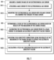
- the method includes measuring 101 a change in mass of an electrochemical gas sensor and determining 102 a status of the electrochemical gas sensor based on results of the measuring of the change in mass.
- the measuring of the change in mass of operation 101 can include attaching 1011 a mass sensor to the electrochemical gas sensor, mounting 1012 the electrochemical gas sensor with the mass sensor in a manner that engages the mass sensor and measuring a mass of the unused or new electrochemical gas sensor.
- the mass sensor can include one or more of a strain gauge assembly, a piezo-electric element, and/or an elastic element.
- the determining of operation 102 can include calibrating 1021 (i.e., at the factory or otherwise prior to electrochemical gas sensor usage) the electrochemical gas sensor prior to a usage thereof to determine an electrolyte sensitivity factor thereof, executing 1022 field sensitivity corrections (i.e., at predefined times, intervals or periodically) using the results of the measuring of the change in mass to update the electrolyte sensitivity factor and calculating 1023 a field gas concentration based on the electrolyte sensitivity factor.
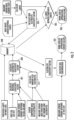
- the calibrating of operation 1021 can include calculating 201 a response sensitivity factor of the electrochemical gas sensor from a sensor mass without electrolyte, from a standard gas test, and from a measurement of a sensor current response during the standard gas test. Also, the calibrating of operation 1021 can include calculating 202 an amount of an acid electrolyte in the electrochemical gas sensor from the sensor mass and the sensor mass with electrolyte at the factory or prior to usage. In addition, the calibrating of operation 1021 can include determining 203 the electrolyte sensitivity factor from the response sensitivity factor and the amount and concentration of the acid electrolyte per the measured sensor mass changes
- the executing of the field sensitivity corrections using the results of the measuring of the change in mass to update the electrolyte sensitivity factor of operation 1022 can include calculating 204 a new electrolyte sensitivity factor from the change in mass and from known mass-based sensor response curves. Also, the executing of the field sensitivity corrections using the results of the measuring of the change in mass to update the electrolyte sensitivity factor of operation 1022 can include determining 205 whether the change in mass is within threshold limits or, if it is in agreement with results from standard electrochemical characterization methods, recent calibration events or historical environmental factors (Temperature, humidity and pressure) and issuing 206 a warning of sensor failure in an event the change in mass is not within the threshold limits.
- the method can further include issuing 207 a warning of sensor failure based on a result of the calculating of the field gas concentration, which takes into account the electrolyte sensitivity factor (original or updated/new) and measured sensor current response at a test site, and inputting into a memory 208 of a processing system 330 (see FIGS. 3-5 ) threshold limits on mass changes and original and updated/new electrolyte sensitivity factors.
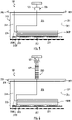
- an electrochemical gas sensor assembly 301 includes an electrochemical gas sensor 310, a mass sensor 320, and the processing system 330.
- the mass sensor 320 is coupled to the electrochemical gas sensor 310 and is configured to measure a change in a mass of the electrochemical gas sensor 310 over time.
- the processing system 330 includes the memory 208 of FIG. 2 and is configured to determine a status of the electrochemical gas sensor 310 based on the change in the mass read by the mass sensor 320.
- the electrochemical gas sensor 310 includes an enclosure 311, an optional printed circuit board (PCB) 312, electrodes 313, and an electrolyte 314.
- the enclosure 311 includes a body 315 that is formed to define an interior 316 and one or more capillary openings (hereinafter referred to as an "opening") 317 by which the interior 316 is communicative with an exterior environment.
- the enclosure 311 may further include a membrane 318, which is disposed on an interior side of the opening 317, and a filter (i.e., a capillary filter) 319, which is disposed on an exterior side of the opening 317.
- the PCB 312 is affixed to an exterior of the body 315 and includes the memory 208 of FIG.
- the electrodes 313 are operably disposed in the interior 316 and are operably coupled with the PCB 312.
- the electrodes 313 can include a counter electrode 3131, a reference electrode 3132 and a sensing (working) electrode 3133.
- the electrolyte 314 fills at least a portion of the interior 316 around the electrodes 313 and can include or be provided as an aqueous or non-aqueous fluid, such as an aqueous acid electrolyte or another similar electrolyte.
- the electrolyte 314 can be diluted over time by water in a humid environment entering the sensor via at least one of: the filter 319, the opening 317, and the membrane 318. This increases the mass of the electrochemical gas sensor 310. Conversely, some quantity of water can evaporate out of the interior 316 in a dry environment from the electrolyte 314 via at least one of: the membrane 318, the opening 317, and the filter 319. This can decrease a mass of the electrochemical gas sensor 310.
- the increase or decrease in the mass of the electrochemical gas sensor 310 correlates with a sensitivity change in the electrochemical gas sensor 310.
- This sensitivity change needs to be taken into account when readings of the electrochemical gas sensor 310 are taken in terms of reliability.
- the sensitivity change can be considered in terms of making a decision about issuing a warning as to the status of the electrochemical gas sensor 310 and/or as to making a decision about replacing the electrochemical gas sensor 310.
- the ability to determine the change in the mass of the electrochemical gas sensor 310 which is provided by the mass sensor 320, is a valuable advance as compared to techniques that never considered the change in mass as being indicative of changes to gas sensor response.
- the processing system 330 can be configured to issue a warning in at least one of: an event the change in the mass exceeds threshold limits, and a mass corrected sensitivity of the electrochemical gas sensor 310 decreases beyond a predefined threshold based on the change in the mass.
- the mass sensor 320 can be attached to the PCB 312 with the electrochemical gas sensor 310 as a whole being effectively suspended on the mass sensor 320.
- the mass sensor 320 can include a deflectable member 321, which can be fastened at opposite ends thereof to a roof or ceiling and affixed at a center thereof to the PCB 312, and a strain gauge 322.
- the deflectable member 321 deflects upwardly or downwardly based on the change in mass of the electrochemical gas sensor 310.
- the strain gauge 322 is capable of detecting the strain associated with this deflection and thus effectively sensing the change in the mass of the electrochemical gas sensor 310.
- the mass sensor 320 can include a piezoelectric element 521, which can be fastened to a roof or ceiling and affixed to the PCB 312.
- the piezoelectric element 521 generates a current based on the change in mass of the electrochemical gas sensor 310. This current can be used to effectively sense the change in the mass of the electrochemical gas sensor 310.
- the mass sensor 320 can include an elastic element 621 and a grid for optical reading 622 which operate similarly as the deflectable member 321 and the strain gauge 322 of FIG. 3 .
- the mass sensor 320 can be provided as a strain gauge 700 or another similar device and can be built-into or integral with a flexible circuit 701 that extends into the interior 316 of the body 315.
- the electrodes 313 can be coupled with the flexible circuit 701 via contact pads 702 of the flexible circuit 701 and the processing system 330 can be incorporated into the flexible circuit 701.
- a sensor clip or housing 710 can be provided to secure the electrochemical gas sensor 310 to the flexible circuit 701 and to ensure that there is good and reliable electrical connections between the electrodes 313 and the contact pads 702.
- the mass sensor 320 may be any electrical or mechanical device capable of measuring a mass change, and, may be positioned on any suitable location capable of providing an accurate indication of a change in mass of the electrochemical gas sensor 310.
- additional features such as accelerometers, gyroscopes and other similar components, can be incorporated either in the sensor assembly or in the detector itself. In any case, these additional features can serve to collect data on alignment of the gas sensor (i.e., in a case of non-vertical alignment in mounting) as well as vibrations (i.e., in a case in which gas detector is mounted in an area of high, expected vibration) in order to correct gravitational measurements accordingly.
Landscapes
- Chemical & Material Sciences (AREA)
- Life Sciences & Earth Sciences (AREA)
- Health & Medical Sciences (AREA)
- Physics & Mathematics (AREA)
- General Physics & Mathematics (AREA)
- Pathology (AREA)
- Immunology (AREA)
- Analytical Chemistry (AREA)
- Biochemistry (AREA)
- General Health & Medical Sciences (AREA)
- Engineering & Computer Science (AREA)
- Molecular Biology (AREA)
- Electrochemistry (AREA)
- Chemical Kinetics & Catalysis (AREA)
- Combustion & Propulsion (AREA)
- Food Science & Technology (AREA)
- Medicinal Chemistry (AREA)
- Investigating Or Analyzing Materials By The Use Of Electric Means (AREA)
- Investigating Or Analyzing Materials By The Use Of Fluid Adsorption Or Reactions (AREA)
Abstract
Description
- The present invention relates to gas detectors and, more particularly, to mass and force indicators in diagnostics and output correction for electrochemical gas sensors in gas detectors.
- The precision and life-span of life-saving toxic gas electrochemical sensors are negatively impacted by long-term extreme environmental conditions. Loss and gain of solvent (often water) in the electrolyte solution (often sulfuric acid) can give rise to corresponding changes in sensitivity toward the target gas. For example, some electrochemical sensors will absorb water vapor in humid environments until they begin leaking/spilling sulfuric acid when the volume of electrolyte exceeds the available internal volume. In the other extreme (dry) case, the sulfuric acid electrolyte may become so concentrated that the acid attacks the materials and seals in the sensor housing, causing leaks and potentially catastrophic detector damage through corrosion. In the other extreme, the loss of electrolyte solution volume may expose the electrodes to air leading to sensor failure.
- To assess the state of the sensor, voltage pulse, current pulse, and impedance spectroscopy are frequently employed; however, these techniques are indirect measurements that may fail to alert to all sensor failures (such as the extreme dry and/or leaking cases scenarios described above).
- According to a first aspect of the invention, there is provided a method of using mass and force indicators in electrochemical gas sensor management. The method includes measuring a change in mass of an electrochemical gas sensor and determining a status of the electrochemical gas sensor based on results of the measuring of the change in mass.
- The measuring of the change in mass may include attaching a mass sensor to the electrochemical gas sensor and mounting the electrochemical gas sensor with the mass sensor in a manner that engages the mass sensor.
- The mass sensor may include one or more of a strain gauge assembly, a piezo-electric element, an elastic element and a flexible circuit with a built-in or integral strain gauge.
- Determining the status of the electrochemical gas sensor based on the results of the measuring of the change in mass may include calibrating the electrochemical gas sensor prior to a usage thereof to determine an electrolyte sensitivity factor thereof, executing field sensitivity corrections using the results of the measuring of the change in mass to update the electrolyte sensitivity factor and calculating a field gas concentration based on the electrolyte sensitivity factor.
- Calibrating the electrochemical gas sensor prior to a usage thereof may include factory calibration.
- Calibrating the electrochemical gas sensor prior to a usage thereof may include calculating a response sensitivity factor of the electrochemical gas sensor, calculating an amount of an acid electrolyte in the electrochemical gas sensor and determining the electrolyte sensitivity factor from the response sensitivity factor and the amount of the acid electrolyte.
- Executing of the field sensitivity corrections may include periodically executing the field sensitivity corrections.
- Executing of the field sensitivity corrections may include determining whether the change in mass is within threshold limits and issuing a warning of sensor failure in an event the change in mass is not within the threshold limits.
- The method may include issuing a warning of sensor failure based on a result of the calculating of the field gas concentration.
- According to a second aspect of the invention, there is provided an electrochemical gas sensor assembly that includes an electrochemical gas sensor, a mass sensor coupled to the electrochemical gas sensor and configured to measure a change in a mass of the electrochemical gas sensor over time and a processing system configured to determine a status of the electrochemical gas sensor based on the change in the mass.
- The electrochemical gas sensor may include an enclosure including a body defining an interior and an opening by which the interior is communicative with an exterior environment, a membrane disposed on an interior side of the opening and a filter disposed on an exterior side of the opening, a printed circuit board (PCB) affixed to an exterior of the body, electrodes operably disposed in the interior and coupled with the PCB and an electrolyte filling at least a portion of the interior around the electrodes.
- The electrolyte may include an aqueous or non-aqueous fluid.
- The aqueous or non-aqueous fluid may be replaceable by water in a humid environment via at least one of: the filter, the opening, and the membrane; and the aqueous or non-aqueous fluid evaporates out of the interior in a dry environment via at least one of: the membrane, the opening, and the filter.
- The mass sensor may be attached to the PCB.
- The electrochemical gas sensor may be suspended on the mass sensor.
- The mass sensor may include a deflectable member and a strain gauge.
- The mass sensor may include a piezoelectric element.
- The mass sensor may include an elastic element and a grid for optical reading.
- The processing system may issue a warning in at least one of: in an event that the change in the mass exceeds threshold limits; and a mass corrected sensitivity of the electrochemical gas sensor decreases beyond a predefined threshold based on the change in the mass.
- In a third aspect of the invention, there is provided an electrochemical gas sensor that includes a flexible circuit and an electrochemical gas sensor suspended on the flexible circuit and including an enclosure that includes a body defining an interior into which the flexible circuit extends and an opening by which the interior is communicative with an exterior environment, a membrane disposed on an interior side of the opening and a filter disposed on an exterior side of the opening, electrodes operably disposed in the interior and coupled with contact pads of the printed circuit board (PCB) and an electrolyte filling at least a portion of the interior around the electrodes. The electrochemical gas sensor further includes a mass sensor built-in or integral with the flexible circuit and configured to measure a change in a mass of the electrochemical gas sensor over time and a processing system configured to determine a status of the electrochemical gas sensor based on the change in the mass.
- The PCB may be affixed to the exterior of the body.
- Additional features and advantages are realized through the techniques of the present disclosure. Other embodiments and aspects of the present invention are described in detail herein and are considered to fall within the scope of the claimed invention. For a better understanding of the invention with the advantages and the features, refer to the description and to the drawings.
- Certain embodiments of the invention will now be described, by way of example only, and with reference to the drawings (wherein like reference numerals represent like parts), in which:
-
FIG. 1 is a flow diagram illustrating a method of using mass and force indicators in electrochemical gas sensor management; -
FIG. 2 is a graphical flow diagram illustrating details of the method ofFIG. 1 ; -
FIG. 3 is a schematic side view of an exemplary electrochemical gas sensor assembly; -
FIG. 4 is a graphical depiction of a relationship between a mass of an electrochemical gas sensor and a mass corrected sensitivity of the electrochemical gas sensor; -
FIG. 5 is a schematic side view of an electrochemical gas sensor assembly; -
FIG. 6 is a schematic side view of an electrochemical gas sensor assembly; and -
FIG. 7 is a schematic side view of an electrochemical gas sensor assembly. - In some, less extreme cases, sensor mass changes are used to correct for the changes in sensor sensitivity to target gases as the electrolyte solution gets more or less concentrated through evaporation or absorption of moisture. These mechanisms affect the viscosity, ion mobility and gas solubility of the electrolyte solution inside the electrochemical gas sensor, which affect sensor sensitivities to target gas.
- As will be described below, losses or gains of water/solvent are directly evident as mass gains or losses that correlate directly with sensitivity changes. This correlation holds over a wide range for the sensors' sensitivity. With today's light-weight polymer sensor housings, the respective change in mass can represent 15-40% of the total sensor mass and is readily measured. Combining this significant mass change with modern methods suitable for measuring the force of an object due to gravity working on it, it becomes easy to implement a direct diagnostics tool. Over most of the useful range, the direct diagnostics tool can be implemented completely without perturbing the electrochemical sensor. Toward the end of the useful life, in an environment where the electrolyte is drying out, it may become advantageous to implement additional diagnostic tools or thresholds which are well known in the prior art. The output from any or all of these diagnostic methods may be employed to warn the user of nearing sensor failure to allow replacement of sensor, or sensor assembly, minimizing downtime.
- With reference to
FIG. 1 , a method of using mass and force indicators in electrochemical gas sensor management is provided. The method includes measuring 101 a change in mass of an electrochemical gas sensor and determining 102 a status of the electrochemical gas sensor based on results of the measuring of the change in mass. The measuring of the change in mass ofoperation 101 can include attaching 1011 a mass sensor to the electrochemical gas sensor, mounting 1012 the electrochemical gas sensor with the mass sensor in a manner that engages the mass sensor and measuring a mass of the unused or new electrochemical gas sensor. In accordance with embodiments, the mass sensor can include one or more of a strain gauge assembly, a piezo-electric element, and/or an elastic element. The determining ofoperation 102 can include calibrating 1021 (i.e., at the factory or otherwise prior to electrochemical gas sensor usage) the electrochemical gas sensor prior to a usage thereof to determine an electrolyte sensitivity factor thereof, executing 1022 field sensitivity corrections (i.e., at predefined times, intervals or periodically) using the results of the measuring of the change in mass to update the electrolyte sensitivity factor and calculating 1023 a field gas concentration based on the electrolyte sensitivity factor. - With reference to
FIG. 2 , further embodiments of the method ofFIG. 1 are illustrated. For example, as shown, the calibrating ofoperation 1021 can include calculating 201 a response sensitivity factor of the electrochemical gas sensor from a sensor mass without electrolyte, from a standard gas test, and from a measurement of a sensor current response during the standard gas test. Also, the calibrating ofoperation 1021 can include calculating 202 an amount of an acid electrolyte in the electrochemical gas sensor from the sensor mass and the sensor mass with electrolyte at the factory or prior to usage. In addition, the calibrating ofoperation 1021 can include determining 203 the electrolyte sensitivity factor from the response sensitivity factor and the amount and concentration of the acid electrolyte per the measured sensor mass changes - As another example, the executing of the field sensitivity corrections using the results of the measuring of the change in mass to update the electrolyte sensitivity factor of
operation 1022 can include calculating 204 a new electrolyte sensitivity factor from the change in mass and from known mass-based sensor response curves. Also, the executing of the field sensitivity corrections using the results of the measuring of the change in mass to update the electrolyte sensitivity factor ofoperation 1022 can include determining 205 whether the change in mass is within threshold limits or, if it is in agreement with results from standard electrochemical characterization methods, recent calibration events or historical environmental factors (Temperature, humidity and pressure) and issuing 206 a warning of sensor failure in an event the change in mass is not within the threshold limits. - As another example, the method can further include issuing 207 a warning of sensor failure based on a result of the calculating of the field gas concentration, which takes into account the electrolyte sensitivity factor (original or updated/new) and measured sensor current response at a test site, and inputting into a
memory 208 of a processing system 330 (seeFIGS. 3-5 ) threshold limits on mass changes and original and updated/new electrolyte sensitivity factors. - With reference to
FIGS. 3-6 , an electrochemicalgas sensor assembly 301 is provided and includes anelectrochemical gas sensor 310, amass sensor 320, and theprocessing system 330. Themass sensor 320 is coupled to theelectrochemical gas sensor 310 and is configured to measure a change in a mass of theelectrochemical gas sensor 310 over time. Theprocessing system 330 includes thememory 208 ofFIG. 2 and is configured to determine a status of theelectrochemical gas sensor 310 based on the change in the mass read by themass sensor 320. - The
electrochemical gas sensor 310 includes anenclosure 311, an optional printed circuit board (PCB) 312,electrodes 313, and anelectrolyte 314. Theenclosure 311 includes abody 315 that is formed to define an interior 316 and one or more capillary openings (hereinafter referred to as an "opening") 317 by which theinterior 316 is communicative with an exterior environment. Theenclosure 311 may further include amembrane 318, which is disposed on an interior side of theopening 317, and a filter (i.e., a capillary filter) 319, which is disposed on an exterior side of theopening 317. ThePCB 312 is affixed to an exterior of thebody 315 and includes thememory 208 ofFIG. 2 and a processor which is configured to read and to execute executable instructions stored in thememory 208 in order to execute the method(s) described herein. Theelectrodes 313 are operably disposed in the interior 316 and are operably coupled with thePCB 312. Theelectrodes 313 can include acounter electrode 3131, areference electrode 3132 and a sensing (working)electrode 3133. Theelectrolyte 314 fills at least a portion of the interior 316 around theelectrodes 313 and can include or be provided as an aqueous or non-aqueous fluid, such as an aqueous acid electrolyte or another similar electrolyte. - In accordance with embodiments, the
electrolyte 314 can be diluted over time by water in a humid environment entering the sensor via at least one of: thefilter 319, theopening 317, and themembrane 318. This increases the mass of theelectrochemical gas sensor 310. Conversely, some quantity of water can evaporate out of the interior 316 in a dry environment from theelectrolyte 314 via at least one of: themembrane 318, theopening 317, and thefilter 319. This can decrease a mass of theelectrochemical gas sensor 310. - As shown in
FIG. 4 , the increase or decrease in the mass of theelectrochemical gas sensor 310 correlates with a sensitivity change in theelectrochemical gas sensor 310. This sensitivity change needs to be taken into account when readings of theelectrochemical gas sensor 310 are taken in terms of reliability. Also, the sensitivity change can be considered in terms of making a decision about issuing a warning as to the status of theelectrochemical gas sensor 310 and/or as to making a decision about replacing theelectrochemical gas sensor 310. As such, the ability to determine the change in the mass of theelectrochemical gas sensor 310, which is provided by themass sensor 320, is a valuable advance as compared to techniques that never considered the change in mass as being indicative of changes to gas sensor response. - The
processing system 330 can be configured to issue a warning in at least one of: an event the change in the mass exceeds threshold limits, and a mass corrected sensitivity of theelectrochemical gas sensor 310 decreases beyond a predefined threshold based on the change in the mass. - With continued reference to at least
FIGS. 3 ,5 and 6 , themass sensor 320 can be attached to thePCB 312 with theelectrochemical gas sensor 310 as a whole being effectively suspended on themass sensor 320. - That is, as shown in
FIG. 3 , themass sensor 320 can include adeflectable member 321, which can be fastened at opposite ends thereof to a roof or ceiling and affixed at a center thereof to thePCB 312, and astrain gauge 322. In this case, thedeflectable member 321 deflects upwardly or downwardly based on the change in mass of theelectrochemical gas sensor 310. Thestrain gauge 322 is capable of detecting the strain associated with this deflection and thus effectively sensing the change in the mass of theelectrochemical gas sensor 310. As shown inFIG. 5 , themass sensor 320 can include apiezoelectric element 521, which can be fastened to a roof or ceiling and affixed to thePCB 312. In this case, thepiezoelectric element 521 generates a current based on the change in mass of theelectrochemical gas sensor 310. This current can be used to effectively sense the change in the mass of theelectrochemical gas sensor 310. As shown inFIG. 6 , themass sensor 320 can include anelastic element 621 and a grid foroptical reading 622 which operate similarly as thedeflectable member 321 and thestrain gauge 322 ofFIG. 3 . - With reference to
FIG. 7 , themass sensor 320 can be provided as astrain gauge 700 or another similar device and can be built-into or integral with aflexible circuit 701 that extends into theinterior 316 of thebody 315. In these or other cases, theelectrodes 313 can be coupled with theflexible circuit 701 viacontact pads 702 of theflexible circuit 701 and theprocessing system 330 can be incorporated into theflexible circuit 701. As shown inFIG. 7 , a sensor clip orhousing 710 can be provided to secure theelectrochemical gas sensor 310 to theflexible circuit 701 and to ensure that there is good and reliable electrical connections between theelectrodes 313 and thecontact pads 702. - It should be appreciated that the
mass sensor 320 may be any electrical or mechanical device capable of measuring a mass change, and, may be positioned on any suitable location capable of providing an accurate indication of a change in mass of theelectrochemical gas sensor 310. It is to be understood that additional features, such as accelerometers, gyroscopes and other similar components, can be incorporated either in the sensor assembly or in the detector itself. In any case, these additional features can serve to collect data on alignment of the gas sensor (i.e., in a case of non-vertical alignment in mounting) as well as vibrations (i.e., in a case in which gas detector is mounted in an area of high, expected vibration) in order to correct gravitational measurements accordingly. - Technical effects and benefits of the present invention are the provision of systems and methods of using mass and force indicators in diagnostics and output corrections for electrochemical gas sensors in gas detectors. Since the mass and force changes translate to changes in concentration and volume of electrolyte, it is possible to assess the electrochemical sensors' sensitivity and to adjust detector output accordingly and to determine if the sensor is approaching or passing a threshold where a replacement should be made. It is also relatively easy to set thresholds to trigger sensor replacements before the sensors begin leaking or before the sensor dries out to expose an electrode to air.
- The corresponding structures, materials, acts, and equivalents of all means or step plus function elements in the claims below are intended to include any structure, material, or act for performing the function in combination with other claimed elements as specifically claimed. The description of the present invention has been presented for purposes of illustration and description, but is not intended to be exhaustive or limited to the technical concepts in the form disclosed. Many modifications and variations will be apparent to those of ordinary skill in the art without departing from the scope of the invention as defined in the claims. The embodiments were chosen and described in order to explain the principles of the invention and the practical application thereof, and to enable others of ordinary skill in the art to understand the disclosure for various embodiments with various modifications as are suited to the particular use contemplated.
- While the preferred embodiments to the invention have been described, it will be understood that those skilled in the art, both now and in the future, may make various improvements and enhancements which fall within the scope of the claims which follow. These claims should be construed to maintain the proper protection for the invention first described.
Claims (14)
- A method of using mass and force indicators in electrochemical gas sensor management, the method comprising:measuring (101) a change in mass of an electrochemical gas sensor (310); anddetermining (102) a status of the electrochemical gas sensor (310) based on results of the measuring of the change in mass.
- The method according to claim 1, wherein the measuring (101) of the change in mass comprises:attaching (1011) a mass sensor (320) to the electrochemical gas sensor (310); andmounting (1012) the electrochemical gas sensor (310) with the mass sensor (320) in a manner that engages the mass sensor (320).
- The method according to claim 2, wherein the mass sensor (320) comprises one or more of a strain gauge assembly (322), a piezo-electric element (521), an elastic element (621), and a flexible circuit (701) with a built-in or integral strain gauge (700).
- The method according to any preceding claim, wherein the determining (102) comprises:calibrating (1021) the electrochemical gas sensor (310) prior to a usage thereof to determine an electrolyte sensitivity factor thereof;executing (1022) field sensitivity corrections using the results of the measuring of the change in mass to update the electrolyte sensitivity factor; andcalculating (1023) a field gas concentration based on the electrolyte sensitivity factor.
- The method according to claim 4, wherein the calibrating (1021) comprises factory calibration; and/or wherein the calibrating (1021) comprises:calculating (201) a response sensitivity factor of the electrochemical gas sensor (310);calculating (202) an amount of an acid electrolyte in the electrochemical gas sensor (310); anddetermining (203) the electrolyte sensitivity factor from the response sensitivity factor and the amount of the acid electrolyte.
- The method according to claim 4 or 5, wherein the executing (1022) of the field sensitivity corrections comprises periodically executing the field sensitivity corrections and/or wherein the executing (1022) of the field sensitivity corrections comprises:determining (205) whether the change in mass is within threshold limits; andissuing (206) a warning of sensor failure in an event the change in mass is not within the threshold limits.
- The method according to claim 4, 5 or 6, further comprising issuing (207) a warning of sensor failure based on a result of the calculating of the field gas concentration.
- An electrochemical gas sensor assembly (301), comprising:an electrochemical gas sensor (310);a mass sensor (320) coupled to the electrochemical gas sensor (310) and configured to measure a change in a mass of the electrochemical gas sensor (310) over time; anda processing system (330) configured to determine a status of the electrochemical gas sensor (310) based on the change in the mass.
- The electrochemical gas sensor assembly (301) according to claim 8, wherein the electrochemical gas sensor (310) comprises:an enclosure (311) comprising a body (315) defining an interior (316) and an opening (317) by which the interior (316) is communicative with an exterior environment, a membrane (318) disposed on an interior side (316) of the opening (317) and a filter (319) disposed on an exterior side of the opening (317);a printed circuit board (PCB) (312) affixed to an exterior of the body (315);electrodes (313) operably disposed in the interior (316) and coupled with the PCB (312); andan electrolyte (314) filling at least a portion of the interior (316) around the electrodes (313).
- The electrochemical gas sensor assembly (301) according to claim 9, wherein the electrolyte (314) comprises an aqueous or non-aqueous fluid; optionally wherein:the aqueous or non-aqueous fluid is replaceable by water in a humid environment via at least one of: the filter (319), the opening (317), and the membrane (318), andthe aqueous or non-aqueous fluid evaporates out of the interior (316) in a dry environment via at least one of: the membrane (318), the opening (317), and the filter (319).
- The electrochemical gas sensor assembly (301) according to claim 9 or 10, wherein the mass sensor (320) is attached to the PCB (312); and/or wherein the electrochemical gas sensor (310) is suspended on the sensor (320).
- The electrochemical gas sensor assembly (301) according to claim 8, 9, 10 or 11, wherein the mass sensor (320) comprises a deflectable member (321) and a strain gauge (322); and/orwherein the mass sensor (320) comprises a piezoelectric element (521); and/orwherein the mass sensor (320) comprises an elastic element (621) and a grid for optical reading (622).
- The electrochemical gas sensor assembly (301) according to claim 8, 9, 10, 11 or 12, wherein the processing system (330) issues a warning in at least one of:an event the change in the mass exceeds threshold limits, anda mass corrected sensitivity of the electrochemical gas sensor (310) decreases beyond a predefined threshold based on the change in the mass.
- An electrochemical gas sensor assembly (301), comprising:a flexible circuit (701);an electrochemical gas sensor (310) suspended on the flexible circuit (701) and comprising an enclosure (311) comprising a body (315) defining an interior (316) into which the flexible circuit (701) extends and an opening (317) by which the interior (316) is communicative with an exterior environment, a membrane (318) disposed on an interior (316) side of the opening (317) and a filter (319) disposed on an exterior side of the opening (317), electrodes (313) operably disposed in the interior (317) and coupled with contact pads of a PCB (312) and an electrolyte (314) filling at least a portion of the interior (316) around the electrodes (313);a mass sensor (320) built-in or integral with the flexible circuit (701) and configured to measure a change in a mass of the electrochemical gas sensor (310) over time; anda processing (330) system configured to determine a status of the electrochemical gas sensor (310) based on the change in the mass.
Applications Claiming Priority (1)
| Application Number | Priority Date | Filing Date | Title |
|---|---|---|---|
| US202163239595P | 2021-09-01 | 2021-09-01 |
Publications (2)
| Publication Number | Publication Date |
|---|---|
| EP4145120A1 true EP4145120A1 (en) | 2023-03-08 |
| EP4145120B1 EP4145120B1 (en) | 2024-12-25 |
Family
ID=83152119
Family Applications (1)
| Application Number | Title | Priority Date | Filing Date |
|---|---|---|---|
| EP22193545.5A Active EP4145120B1 (en) | 2021-09-01 | 2022-09-01 | Mass and force indicators in diagnostics and output correction for electrochemical gas sensors |
Country Status (2)
| Country | Link |
|---|---|
| US (1) | US20230061393A1 (en) |
| EP (1) | EP4145120B1 (en) |
Citations (2)
| Publication number | Priority date | Publication date | Assignee | Title |
|---|---|---|---|---|
| US5580675A (en) * | 1994-08-11 | 1996-12-03 | Lockheed Idaho Technologies Company | Method and apparatus for indicating electric charge remaining in batteries based on electrode weight and center of gravity |
| US6629444B2 (en) * | 2001-08-08 | 2003-10-07 | Industrial Scientific Corporation | Method and apparatus for diagnosing gas sensors |
-
2022
- 2022-08-29 US US17/898,211 patent/US20230061393A1/en active Pending
- 2022-09-01 EP EP22193545.5A patent/EP4145120B1/en active Active
Patent Citations (2)
| Publication number | Priority date | Publication date | Assignee | Title |
|---|---|---|---|---|
| US5580675A (en) * | 1994-08-11 | 1996-12-03 | Lockheed Idaho Technologies Company | Method and apparatus for indicating electric charge remaining in batteries based on electrode weight and center of gravity |
| US6629444B2 (en) * | 2001-08-08 | 2003-10-07 | Industrial Scientific Corporation | Method and apparatus for diagnosing gas sensors |
Also Published As
| Publication number | Publication date |
|---|---|
| US20230061393A1 (en) | 2023-03-02 |
| EP4145120B1 (en) | 2024-12-25 |
Similar Documents
| Publication | Publication Date | Title |
|---|---|---|
| US8317998B2 (en) | Methods of operation of electrochemical gas sensors | |
| EP3183566B1 (en) | Automated self-compensation apparatus and method for providing electro-chemical sensors | |
| JP5530544B2 (en) | Composite electrode ion probe | |
| KR102641537B1 (en) | Thermal conductive type gas detection sensor | |
| US20080251379A1 (en) | Electrochemical sensor with zero calibration feature and method of calibrating | |
| CN114207426A (en) | Interrogation of Capillary Restricted Sensors | |
| EP3809125B1 (en) | Breathalyzer capable of estimating remaining life of detection unit | |
| US20230375424A1 (en) | Sensor device and method for detecting the internal pressure and/or a change in the internal pressure in a gas-tight internal volume of a housing component | |
| EP4145120B1 (en) | Mass and force indicators in diagnostics and output correction for electrochemical gas sensors | |
| US20230184665A1 (en) | Corrosion Testing Device | |
| JP5164736B2 (en) | Load cell | |
| JPH09159561A (en) | Pressure sensor and gas abnormality monitoring device using this pressure sensor | |
| KR102448945B1 (en) | Automatic calibration method of electrochemical electrode sensor transducer through EIS measurement and algorithm method, method of diagnosing the life of electrochemical electrode sensor transducer through EIS measurement and algorithm method, and electrochemical electrode sensor transducer through EIS measurement and algorithm method Diagnosis method | |
| US10145771B2 (en) | Method, device and computer medium for determining the density of liquids | |
| CN117871326A (en) | Micro-water density on-line monitoring system and method | |
| JP5112119B2 (en) | Gas detector | |
| CN109844512B (en) | Electrochemical sensor comprising an internal reference cell | |
| US9052282B2 (en) | Water analysis measurement arrangement | |
| RU237047U1 (en) | Combined corrosion rate sensor | |
| US20260029371A1 (en) | Use and method for detecting the state of an electrochemical sensor, and corresponding electrochemical sensor | |
| JP2023530432A (en) | Gas and environmental parameter measuring device | |
| JP2021124472A (en) | Composite sensor | |
| SU319851A1 (en) | DISCRETE LEVEL | |
| JPH09273970A (en) | Capacitive pressure sensor and gas abnormality monitoring device using this sensor |
Legal Events
| Date | Code | Title | Description |
|---|---|---|---|
| PUAI | Public reference made under article 153(3) epc to a published international application that has entered the european phase |
Free format text: ORIGINAL CODE: 0009012 |
|
| STAA | Information on the status of an ep patent application or granted ep patent |
Free format text: STATUS: THE APPLICATION HAS BEEN PUBLISHED |
|
| AK | Designated contracting states |
Kind code of ref document: A1 Designated state(s): AL AT BE BG CH CY CZ DE DK EE ES FI FR GB GR HR HU IE IS IT LI LT LU LV MC MK MT NL NO PL PT RO RS SE SI SK SM TR |
|
| STAA | Information on the status of an ep patent application or granted ep patent |
Free format text: STATUS: REQUEST FOR EXAMINATION WAS MADE |
|
| 17P | Request for examination filed |
Effective date: 20230908 |
|
| RBV | Designated contracting states (corrected) |
Designated state(s): AL AT BE BG CH CY CZ DE DK EE ES FI FR GB GR HR HU IE IS IT LI LT LU LV MC MK MT NL NO PL PT RO RS SE SI SK SM TR |
|
| RIC1 | Information provided on ipc code assigned before grant |
Ipc: G01L 1/22 20060101ALI20240714BHEP Ipc: G01L 1/16 20060101ALI20240714BHEP Ipc: G01N 33/00 20060101ALI20240714BHEP Ipc: G01N 27/416 20060101ALI20240714BHEP Ipc: G01N 27/404 20060101AFI20240714BHEP |
|
| GRAP | Despatch of communication of intention to grant a patent |
Free format text: ORIGINAL CODE: EPIDOSNIGR1 |
|
| STAA | Information on the status of an ep patent application or granted ep patent |
Free format text: STATUS: GRANT OF PATENT IS INTENDED |
|
| INTG | Intention to grant announced |
Effective date: 20240823 |
|
| RIN1 | Information on inventor provided before grant (corrected) |
Inventor name: FILLMORE, ROBERT L. Inventor name: EVJU, JON K. |
|
| GRAS | Grant fee paid |
Free format text: ORIGINAL CODE: EPIDOSNIGR3 |
|
| GRAA | (expected) grant |
Free format text: ORIGINAL CODE: 0009210 |
|
| STAA | Information on the status of an ep patent application or granted ep patent |
Free format text: STATUS: THE PATENT HAS BEEN GRANTED |
|
| AK | Designated contracting states |
Kind code of ref document: B1 Designated state(s): AL AT BE BG CH CY CZ DE DK EE ES FI FR GB GR HR HU IE IS IT LI LT LU LV MC MK MT NL NO PL PT RO RS SE SI SK SM TR |
|
| REG | Reference to a national code |
Ref country code: GB Ref legal event code: FG4D |
|
| REG | Reference to a national code |
Ref country code: CH Ref legal event code: EP |
|
| REG | Reference to a national code |
Ref country code: DE Ref legal event code: R096 Ref document number: 602022009046 Country of ref document: DE |
|
| REG | Reference to a national code |
Ref country code: IE Ref legal event code: FG4D |
|
| REG | Reference to a national code |
Ref country code: LT Ref legal event code: MG9D |
|
| PG25 | Lapsed in a contracting state [announced via postgrant information from national office to epo] |
Ref country code: HR Free format text: LAPSE BECAUSE OF FAILURE TO SUBMIT A TRANSLATION OF THE DESCRIPTION OR TO PAY THE FEE WITHIN THE PRESCRIBED TIME-LIMIT Effective date: 20241225 |
|
| PG25 | Lapsed in a contracting state [announced via postgrant information from national office to epo] |
Ref country code: FI Free format text: LAPSE BECAUSE OF FAILURE TO SUBMIT A TRANSLATION OF THE DESCRIPTION OR TO PAY THE FEE WITHIN THE PRESCRIBED TIME-LIMIT Effective date: 20241225 |
|
| PG25 | Lapsed in a contracting state [announced via postgrant information from national office to epo] |
Ref country code: BG Free format text: LAPSE BECAUSE OF FAILURE TO SUBMIT A TRANSLATION OF THE DESCRIPTION OR TO PAY THE FEE WITHIN THE PRESCRIBED TIME-LIMIT Effective date: 20241225 |
|
| PG25 | Lapsed in a contracting state [announced via postgrant information from national office to epo] |
Ref country code: GR Free format text: LAPSE BECAUSE OF FAILURE TO SUBMIT A TRANSLATION OF THE DESCRIPTION OR TO PAY THE FEE WITHIN THE PRESCRIBED TIME-LIMIT Effective date: 20250326 Ref country code: LV Free format text: LAPSE BECAUSE OF FAILURE TO SUBMIT A TRANSLATION OF THE DESCRIPTION OR TO PAY THE FEE WITHIN THE PRESCRIBED TIME-LIMIT Effective date: 20241225 |
|
| PG25 | Lapsed in a contracting state [announced via postgrant information from national office to epo] |
Ref country code: RS Free format text: LAPSE BECAUSE OF FAILURE TO SUBMIT A TRANSLATION OF THE DESCRIPTION OR TO PAY THE FEE WITHIN THE PRESCRIBED TIME-LIMIT Effective date: 20250325 |
|
| REG | Reference to a national code |
Ref country code: NL Ref legal event code: MP Effective date: 20241225 |
|
| PG25 | Lapsed in a contracting state [announced via postgrant information from national office to epo] |
Ref country code: NL Free format text: LAPSE BECAUSE OF FAILURE TO SUBMIT A TRANSLATION OF THE DESCRIPTION OR TO PAY THE FEE WITHIN THE PRESCRIBED TIME-LIMIT Effective date: 20241225 |
|
| REG | Reference to a national code |
Ref country code: AT Ref legal event code: MK05 Ref document number: 1754561 Country of ref document: AT Kind code of ref document: T Effective date: 20241225 |
|
| PG25 | Lapsed in a contracting state [announced via postgrant information from national office to epo] |
Ref country code: SM Free format text: LAPSE BECAUSE OF FAILURE TO SUBMIT A TRANSLATION OF THE DESCRIPTION OR TO PAY THE FEE WITHIN THE PRESCRIBED TIME-LIMIT Effective date: 20241225 |
|
| PG25 | Lapsed in a contracting state [announced via postgrant information from national office to epo] |
Ref country code: PL Free format text: LAPSE BECAUSE OF FAILURE TO SUBMIT A TRANSLATION OF THE DESCRIPTION OR TO PAY THE FEE WITHIN THE PRESCRIBED TIME-LIMIT Effective date: 20241225 |
|
| PG25 | Lapsed in a contracting state [announced via postgrant information from national office to epo] |
Ref country code: ES Free format text: LAPSE BECAUSE OF FAILURE TO SUBMIT A TRANSLATION OF THE DESCRIPTION OR TO PAY THE FEE WITHIN THE PRESCRIBED TIME-LIMIT Effective date: 20241225 |
|
| PG25 | Lapsed in a contracting state [announced via postgrant information from national office to epo] |
Ref country code: IS Free format text: LAPSE BECAUSE OF FAILURE TO SUBMIT A TRANSLATION OF THE DESCRIPTION OR TO PAY THE FEE WITHIN THE PRESCRIBED TIME-LIMIT Effective date: 20250425 |
|
| PG25 | Lapsed in a contracting state [announced via postgrant information from national office to epo] |
Ref country code: PT Free format text: LAPSE BECAUSE OF FAILURE TO SUBMIT A TRANSLATION OF THE DESCRIPTION OR TO PAY THE FEE WITHIN THE PRESCRIBED TIME-LIMIT Effective date: 20250428 |
|
| PG25 | Lapsed in a contracting state [announced via postgrant information from national office to epo] |
Ref country code: EE Free format text: LAPSE BECAUSE OF FAILURE TO SUBMIT A TRANSLATION OF THE DESCRIPTION OR TO PAY THE FEE WITHIN THE PRESCRIBED TIME-LIMIT Effective date: 20241225 |
|
| PG25 | Lapsed in a contracting state [announced via postgrant information from national office to epo] |
Ref country code: AT Free format text: LAPSE BECAUSE OF FAILURE TO SUBMIT A TRANSLATION OF THE DESCRIPTION OR TO PAY THE FEE WITHIN THE PRESCRIBED TIME-LIMIT Effective date: 20241225 Ref country code: RO Free format text: LAPSE BECAUSE OF FAILURE TO SUBMIT A TRANSLATION OF THE DESCRIPTION OR TO PAY THE FEE WITHIN THE PRESCRIBED TIME-LIMIT Effective date: 20241225 |
|
| PG25 | Lapsed in a contracting state [announced via postgrant information from national office to epo] |
Ref country code: SK Free format text: LAPSE BECAUSE OF FAILURE TO SUBMIT A TRANSLATION OF THE DESCRIPTION OR TO PAY THE FEE WITHIN THE PRESCRIBED TIME-LIMIT Effective date: 20241225 |
|
| PG25 | Lapsed in a contracting state [announced via postgrant information from national office to epo] |
Ref country code: CZ Free format text: LAPSE BECAUSE OF FAILURE TO SUBMIT A TRANSLATION OF THE DESCRIPTION OR TO PAY THE FEE WITHIN THE PRESCRIBED TIME-LIMIT Effective date: 20241225 |
|
| PG25 | Lapsed in a contracting state [announced via postgrant information from national office to epo] |
Ref country code: IT Free format text: LAPSE BECAUSE OF FAILURE TO SUBMIT A TRANSLATION OF THE DESCRIPTION OR TO PAY THE FEE WITHIN THE PRESCRIBED TIME-LIMIT Effective date: 20241225 |
|
| PG25 | Lapsed in a contracting state [announced via postgrant information from national office to epo] |
Ref country code: SE Free format text: LAPSE BECAUSE OF FAILURE TO SUBMIT A TRANSLATION OF THE DESCRIPTION OR TO PAY THE FEE WITHIN THE PRESCRIBED TIME-LIMIT Effective date: 20241225 |
|
| REG | Reference to a national code |
Ref country code: DE Ref legal event code: R097 Ref document number: 602022009046 Country of ref document: DE |
|
| PG25 | Lapsed in a contracting state [announced via postgrant information from national office to epo] |
Ref country code: DK Free format text: LAPSE BECAUSE OF FAILURE TO SUBMIT A TRANSLATION OF THE DESCRIPTION OR TO PAY THE FEE WITHIN THE PRESCRIBED TIME-LIMIT Effective date: 20241225 |
|
| PGFP | Annual fee paid to national office [announced via postgrant information from national office to epo] |
Ref country code: DE Payment date: 20250820 Year of fee payment: 4 |
|
| PGFP | Annual fee paid to national office [announced via postgrant information from national office to epo] |
Ref country code: NO Payment date: 20250825 Year of fee payment: 4 |
|
| PGFP | Annual fee paid to national office [announced via postgrant information from national office to epo] |
Ref country code: FR Payment date: 20250820 Year of fee payment: 4 |
|
| PLBE | No opposition filed within time limit |
Free format text: ORIGINAL CODE: 0009261 |
|
| STAA | Information on the status of an ep patent application or granted ep patent |
Free format text: STATUS: NO OPPOSITION FILED WITHIN TIME LIMIT |
|
| REG | Reference to a national code |
Ref country code: CH Ref legal event code: L10 Free format text: ST27 STATUS EVENT CODE: U-0-0-L10-L00 (AS PROVIDED BY THE NATIONAL OFFICE) Effective date: 20251105 |
|
| 26N | No opposition filed |
Effective date: 20250926 |
|
| REG | Reference to a national code |
Ref country code: DE Ref legal event code: R081 Ref document number: 602022009046 Country of ref document: DE Owner name: DETECTOR ELECTRONICS BUYER US, LLC, BLOOMINGTO, US Free format text: FORMER OWNER: CARRIER CORPORATION, PALM BEACH GARDENS, FL, US |
|
| REG | Reference to a national code |
Ref country code: GB Ref legal event code: 732E Free format text: REGISTERED BETWEEN 20260305 AND 20260311 |
|
| REG | Reference to a national code |
Ref country code: CH Ref legal event code: H13 Free format text: ST27 STATUS EVENT CODE: U-0-0-H10-H13 (AS PROVIDED BY THE NATIONAL OFFICE) Effective date: 20260504 |