EP4144991A1 - Oil pump gas-exhaust mechanism for automatic transmission, and automatic transmission and vehicle - Google Patents
Oil pump gas-exhaust mechanism for automatic transmission, and automatic transmission and vehicle Download PDFInfo
- Publication number
- EP4144991A1 EP4144991A1 EP20941421.8A EP20941421A EP4144991A1 EP 4144991 A1 EP4144991 A1 EP 4144991A1 EP 20941421 A EP20941421 A EP 20941421A EP 4144991 A1 EP4144991 A1 EP 4144991A1
- Authority
- EP
- European Patent Office
- Prior art keywords
- oil pump
- automatic transmission
- assembly
- gas
- sensor plug
- Prior art date
- Legal status (The legal status is an assumption and is not a legal conclusion. Google has not performed a legal analysis and makes no representation as to the accuracy of the status listed.)
- Granted
Links
Images

Classifications
-
- F—MECHANICAL ENGINEERING; LIGHTING; HEATING; WEAPONS; BLASTING
- F16—ENGINEERING ELEMENTS AND UNITS; GENERAL MEASURES FOR PRODUCING AND MAINTAINING EFFECTIVE FUNCTIONING OF MACHINES OR INSTALLATIONS; THERMAL INSULATION IN GENERAL
- F16H—GEARING
- F16H57/00—General details of gearing
- F16H57/04—Features relating to lubrication or cooling or heating
- F16H57/0434—Features relating to lubrication or cooling or heating relating to lubrication supply, e.g. pumps; Pressure control
- F16H57/0436—Pumps
-
- F—MECHANICAL ENGINEERING; LIGHTING; HEATING; WEAPONS; BLASTING
- F04—POSITIVE - DISPLACEMENT MACHINES FOR LIQUIDS; PUMPS FOR LIQUIDS OR ELASTIC FLUIDS
- F04C—ROTARY-PISTON, OR OSCILLATING-PISTON, POSITIVE-DISPLACEMENT MACHINES FOR LIQUIDS; ROTARY-PISTON, OR OSCILLATING-PISTON, POSITIVE-DISPLACEMENT PUMPS
- F04C14/00—Control of, monitoring of, or safety arrangements for, machines, pumps or pumping installations
- F04C14/28—Safety arrangements; Monitoring
-
- F—MECHANICAL ENGINEERING; LIGHTING; HEATING; WEAPONS; BLASTING
- F04—POSITIVE - DISPLACEMENT MACHINES FOR LIQUIDS; PUMPS FOR LIQUIDS OR ELASTIC FLUIDS
- F04C—ROTARY-PISTON, OR OSCILLATING-PISTON, POSITIVE-DISPLACEMENT MACHINES FOR LIQUIDS; ROTARY-PISTON, OR OSCILLATING-PISTON, POSITIVE-DISPLACEMENT PUMPS
- F04C2/00—Rotary-piston machines or pumps
- F04C2/08—Rotary-piston machines or pumps of intermeshing-engagement type, i.e. with engagement of co-operating members similar to that of toothed gearing
- F04C2/10—Rotary-piston machines or pumps of intermeshing-engagement type, i.e. with engagement of co-operating members similar to that of toothed gearing of internal-axis type with the outer member having more teeth or tooth-equivalents, e.g. rollers, than the inner member
- F04C2/101—Rotary-piston machines or pumps of intermeshing-engagement type, i.e. with engagement of co-operating members similar to that of toothed gearing of internal-axis type with the outer member having more teeth or tooth-equivalents, e.g. rollers, than the inner member with a crescent-shaped filler element, located between the inner and outer intermeshing members
-
- F—MECHANICAL ENGINEERING; LIGHTING; HEATING; WEAPONS; BLASTING
- F16—ENGINEERING ELEMENTS AND UNITS; GENERAL MEASURES FOR PRODUCING AND MAINTAINING EFFECTIVE FUNCTIONING OF MACHINES OR INSTALLATIONS; THERMAL INSULATION IN GENERAL
- F16H—GEARING
- F16H57/00—General details of gearing
- F16H57/04—Features relating to lubrication or cooling or heating
- F16H57/0434—Features relating to lubrication or cooling or heating relating to lubrication supply, e.g. pumps; Pressure control
- F16H57/0443—Features relating to lubrication or cooling or heating relating to lubrication supply, e.g. pumps; Pressure control for supply of lubricant during tilt or high acceleration, e.g. problems related to the tilt or extreme acceleration of the transmission casing and the supply of lubricant under these conditions
-
- F—MECHANICAL ENGINEERING; LIGHTING; HEATING; WEAPONS; BLASTING
- F04—POSITIVE - DISPLACEMENT MACHINES FOR LIQUIDS; PUMPS FOR LIQUIDS OR ELASTIC FLUIDS
- F04C—ROTARY-PISTON, OR OSCILLATING-PISTON, POSITIVE-DISPLACEMENT MACHINES FOR LIQUIDS; ROTARY-PISTON, OR OSCILLATING-PISTON, POSITIVE-DISPLACEMENT PUMPS
- F04C2210/00—Fluid
- F04C2210/20—Fluid liquid, i.e. incompressible
- F04C2210/206—Oil
-
- F—MECHANICAL ENGINEERING; LIGHTING; HEATING; WEAPONS; BLASTING
- F04—POSITIVE - DISPLACEMENT MACHINES FOR LIQUIDS; PUMPS FOR LIQUIDS OR ELASTIC FLUIDS
- F04C—ROTARY-PISTON, OR OSCILLATING-PISTON, POSITIVE-DISPLACEMENT MACHINES FOR LIQUIDS; ROTARY-PISTON, OR OSCILLATING-PISTON, POSITIVE-DISPLACEMENT PUMPS
- F04C2220/00—Application
- F04C2220/20—Pumps with means for separating and evacuating the gaseous phase
-
- F—MECHANICAL ENGINEERING; LIGHTING; HEATING; WEAPONS; BLASTING
- F04—POSITIVE - DISPLACEMENT MACHINES FOR LIQUIDS; PUMPS FOR LIQUIDS OR ELASTIC FLUIDS
- F04C—ROTARY-PISTON, OR OSCILLATING-PISTON, POSITIVE-DISPLACEMENT MACHINES FOR LIQUIDS; ROTARY-PISTON, OR OSCILLATING-PISTON, POSITIVE-DISPLACEMENT PUMPS
- F04C2240/00—Components
- F04C2240/80—Other components
- F04C2240/81—Sensor, e.g. electronic sensor for control or monitoring
Definitions
- the present application relates to the technical field of automobile transmission, and in particular to an oil pump gas-exhaust mechanism for an automatic transmission, and an automatic transmission and a vehicle.
- a transmission (also known as a gear box) is a component of an automobile, and is divided into a manual transmission and an automatic transmission.
- the manual transmission is mainly composed of gears and shafts, and speed change and torque conversion are generated by means of different gear combinations; while the automatic transmission is composed of a hydraulic torque converter, planet gears, and a hydraulic control system, and the speed change and torque conversion are achieved by means of hydraulic transmission and the gear combinations.
- Main functions of the transmission are: first, changing a transmission ratio; second, enabling the automobile to travel backwards when a rotation direction of an engine remains unchanged; and third, interrupting power transmission by using neutral gear, so as to enable the engine to start and idle, and facilitate gear shifting or power output of the transmission.
- An oil pump for the automatic transmission as a power source of a clutch system of the automatic transmission and each friction pair lubrication device inside the gear box, is an important portion of the automatic transmission and one of key components related to the performances of power, economy and comfort of the automobile.
- the influence of the oil pump for the automatic transmission on fuel consumption, performance, and price of a whole vehicle cannot be underestimated.
- a working principle of the oil pump for the automatic transmission is that engaging rotor assemblies of the oil pump rotate, and a fluid is sucked and discharged by changing a volume formed by engaging rotors and a housing having a suction port and a discharging port.
- the oil pump for the automatic transmission is divided into two types: an external gear pump and an internal gear pump.
- the external gear pump has some disadvantages, such as a high flow pulsation rate, loud noise, and serious oil trapping. Therefore, in order to improve the performance of noise, vibration, and harshness (NVH) of the transmission and make the structure more compact, an internal gear electronic oil pump is often used by the automatic transmission.
- the internal gear electronic oil pump has the advantages of a compact structure, a strong self-priming capability, a small flow fluctuation, and low noise. Because the transmission is exposed at the bottom of a vehicle, there is a risk of water entering the electronic oil pump when the whole vehicle is not protected by a bottom protective plate, and the vehicle travels to a wading road or there is water splashing on the road, which may affect normal working of the electronic oil pump.
- the purpose of the present application is to provide an oil pump gas-exhaust mechanism for an automatic transmission, and an automatic transmission and a vehicle.
- An inclined gas exhaust hole is arranged on a sensor plug-in assembly, so that water splashing into an electronic oil pump can be avoided when a vehicle is wading, thus ensuring normal working of the oil pump when the vehicle is in a working condition involving wading.
- the present application provides an oil pump gas-exhaust mechanism for an automatic transmission, the oil pump gas-exhaust mechanism including a sensor plug-in assembly and an oil pump for supplying oil to the automatic transmission;
- the oil pump is fixedly connected to a transmission case, the sensor plug-in assembly is provided on a housing of the oil pump, the sensor plug-in assembly is located between the oil pump and the transmission, and the sensor plug-in assembly is used to be electrically connected to a sensor;
- a gas exhaust hole is provided on the sensor plug-in assembly, and the gas exhaust hole is inclined upwards from an outlet end relative to a horizontal plane.
- the gas exhaust hole includes a vertical section and an inclined section successively arranged from the inside of the sensor plug-in assembly, where the vertical section is perpendicular to the horizontal plane, and the inclined section is inclined upwards from the outlet end relative to the horizontal plane.
- the oil pump has a joint surface joined with the transmission case, and a distance from the outlet end of the gas exhaust hole to the joint surface is a preset distance.
- a waterproof base membrane is further included, where the waterproof base membrane is provided inside the sensor plug-in assembly, and the waterproof base membrane seals one end of the gas exhaust hole close to the inside of the sensor plug-in assembly.
- the waterproof base membrane is fixed to the inside of the sensor plug-in assembly in a bonding manner.
- the joint surface is positioned on the transmission case by means of a pin hole, and is fixedly connected to the transmission case by means of a bolt.
- the oil pump is an internal gear pump, including an external gear, an internal gear, a crescent-shaped diaphragm, and a pump housing, where the external gear and the internal gear are both arranged in a cavity inside the pump housing, the external gear is a driving gear, the internal gear is a driven gear, and the crescent-shaped diaphragm separates the external gear from the internal gear.
- the oil pump further includes an oil inlet and an oil outlet, where the oil inlet is used to suck hydraulic oil, and the oil outlet is used to discharge the hydraulic oil.
- the present application further provides an automatic transmission including the oil pump gas-exhaust mechanism for an automatic transmission.
- the present application further provides a vehicle including the automatic transmission.
- the reference numerals in the figures correspond to: 1 joint surface, 2-gas exhaust hole, 3-sensor plug-in assembly, 4-waterproof base membrane, and L-distance from an outlet end of the gas exhaust hole to the joint surface.
- connection may be a fixed connection, a detachable connection, or an integrated connection, may be a mechanical connection or an electrical connection, may be a direct connection or an indirect connection by means of an intermediate medium, or may be an internal connection of two elements or an interaction between two elements.
- connection may be a fixed connection, a detachable connection, or an integrated connection, may be a mechanical connection or an electrical connection, may be a direct connection or an indirect connection by means of an intermediate medium, or may be an internal connection of two elements or an interaction between two elements.
- the embodiment provides an oil pump gas-exhaust mechanism for an automatic transmission.
- the oil pump gas-exhaust mechanism for an automatic transmission in this embodiment includes a sensor plug-in assembly 3 and an oil pump for supplying oil to the automatic transmission; the oil pump is fixedly connected to a transmission case, the sensor plug-in assembly 3 is arranged on a housing of the oil pump, and the sensor plug-in assembly 3 is used to be electrically connected to a sensor; and a gas exhaust hole 2 is provided on the sensor plug-in assembly 3, the gas exhaust hole 2 is located between the oil pump and the transmission, the gas exhaust hole 2 is an inclined hole, and the gas exhaust hole 2 is inclined upwards from an outlet end relative to a horizontal plane.
- the gas exhaust hole 2 is provided on the sensor plug-in assembly 3, and to facilitate a hole opening design, the exhaust hole 2 is arranged as the inclined hole inclined upwards relative to a direction of the horizontal plane.
- the pressure generated during the working of the oil pump can be ensured to be discharged by means of the gas exhaust hole.
- the oil pump for the automatic transmission avoids an active "water retention” phenomenon due to the gravity of water droplets, so that water or other foreign matters can be prevented from splashing into the electronic oil pump when the vehicle is wading, thereby ensuring the normal working of the oil pump when the vehicle is in the working condition involving wading.
- the gas exhaust hole 2 includes an inclined section and a vertical section successively arranged from the inside of the sensor plug-in assembly 3, where the vertical section is close to the sensor plug-in assembly 3 and is perpendicular to the horizontal plane, and the inclined section is inclined upwards from the outlet end relative to the horizontal plane.
- the oil pump has a joint surface 1 that is joined with the transmission case.
- a distance L from the outlet end of the gas exhaust hole 2 to the joint surface 1 is a preset distance, and specifically, the preset distance may be 2 mm to 5 mm.
- the distance from the gas exhaust hole 2 to the joint surface 1 may further be adjusted based on a traveling condition of the vehicle, as long as the same function can be achieved.
- a waterproof base membrane 4 is further included, where the waterproof base membrane 4 has both waterproof and gas-permeable functions, and the waterproof base membrane 4 seals one end of the gas exhaust hole 2 close to the inside of the sensor plug-in assembly 3.
- the waterproof base membrane 4 is provided inside the sensor plug-in assembly 3, that is, the waterproof base membrane 4 seals an end portion of the vertical section located at the sensor plug-in assembly 3.
- the waterproof base membrane 4 arranged at a hole port inside the sensor plug-in assembly 3 ensures that heat generated by the working of the oil pump can be discharged, and a situation in which water is forced to flow back into the oil pump when undergoing serious wading can also be avoided, so that the inclined gas exhaust hole 2 and the waterproof base membrane 4 achieve a double protection effect for the oil pump when the vehicle is in a traveling condition involving serious wading, enabling the oil pump to always maintain optimal performance under a severe traveling condition of an automobile.
- the waterproof base membrane 4 is fixed to the inside of the sensor plug-in assembly 3 in a bonding manner.
- the connection manner is simple, stable, and reliable, and is convenient for mounting, disassembly, and replacement.
- the waterproof base membrane 4 may further be fixed inside the sensor plug-in assembly 3 in another connection manner, as long as the same function can be achieved.
- the joint surface 1 of the oil pump is positioned on the transmission case by means of a pin hole, and is fixedly connected to the transmission case by means of a bolt.
- the connection manner is simple and reliable, and is easy to assemble.
- the oil pump is an internal gear pump, including an external gear, an internal gear, a crescent-shaped diaphragm, and a pump housing, where the external gear and the internal gear are both arranged in a cavity inside the pump housing, the external gear is a driving gear, the internal gear is a driven gear, and the crescent-shaped diaphragm separates the external gear from the internal gear.
- the oil pump further includes an oil inlet and an oil outlet, where the oil inlet is used to suck hydraulic oil, and the oil outlet is used to discharge the hydraulic oil.
- the embodiment of the present application further provides an automatic transmission including the oil pump gas-exhaust mechanism for an automatic transmission.
- the embodiment of the present application further provides a vehicle including the automatic transmission.
Landscapes
- Engineering & Computer Science (AREA)
- General Engineering & Computer Science (AREA)
- Mechanical Engineering (AREA)
- General Details Of Gearings (AREA)
- Control Of Transmission Device (AREA)
Abstract
Description
- The present application relates to the technical field of automobile transmission, and in particular to an oil pump gas-exhaust mechanism for an automatic transmission, and an automatic transmission and a vehicle.
- A transmission (also known as a gear box) is a component of an automobile, and is divided into a manual transmission and an automatic transmission. The manual transmission is mainly composed of gears and shafts, and speed change and torque conversion are generated by means of different gear combinations; while the automatic transmission is composed of a hydraulic torque converter, planet gears, and a hydraulic control system, and the speed change and torque conversion are achieved by means of hydraulic transmission and the gear combinations. Main functions of the transmission are: first, changing a transmission ratio; second, enabling the automobile to travel backwards when a rotation direction of an engine remains unchanged; and third, interrupting power transmission by using neutral gear, so as to enable the engine to start and idle, and facilitate gear shifting or power output of the transmission. At present, with the development of the automobile industry, the automatic transmission has become a development trend. An oil pump for the automatic transmission, as a power source of a clutch system of the automatic transmission and each friction pair lubrication device inside the gear box, is an important portion of the automatic transmission and one of key components related to the performances of power, economy and comfort of the automobile. The influence of the oil pump for the automatic transmission on fuel consumption, performance, and price of a whole vehicle cannot be underestimated.
- A working principle of the oil pump for the automatic transmission is that engaging rotor assemblies of the oil pump rotate, and a fluid is sucked and discharged by changing a volume formed by engaging rotors and a housing having a suction port and a discharging port. Based on the structure of a rotor of the oil pump, the oil pump for the automatic transmission is divided into two types: an external gear pump and an internal gear pump. The external gear pump has some disadvantages, such as a high flow pulsation rate, loud noise, and serious oil trapping. Therefore, in order to improve the performance of noise, vibration, and harshness (NVH) of the transmission and make the structure more compact, an internal gear electronic oil pump is often used by the automatic transmission. The internal gear electronic oil pump has the advantages of a compact structure, a strong self-priming capability, a small flow fluctuation, and low noise. Because the transmission is exposed at the bottom of a vehicle, there is a risk of water entering the electronic oil pump when the whole vehicle is not protected by a bottom protective plate, and the vehicle travels to a wading road or there is water splashing on the road, which may affect normal working of the electronic oil pump.
- Therefore, it is necessary to propose an oil pump gas-exhaust mechanism for an automatic transmission, an automatic transmission and a vehicle to solve the above technical problem.
- The purpose of the present application is to provide an oil pump gas-exhaust mechanism for an automatic transmission, and an automatic transmission and a vehicle. An inclined gas exhaust hole is arranged on a sensor plug-in assembly, so that water splashing into an electronic oil pump can be avoided when a vehicle is wading, thus ensuring normal working of the oil pump when the vehicle is in a working condition involving wading.
- The present application is implemented by means of the following technical solutions:
the present application provides an oil pump gas-exhaust mechanism for an automatic transmission, the oil pump gas-exhaust mechanism including a sensor plug-in assembly and an oil pump for supplying oil to the automatic transmission; the oil pump is fixedly connected to a transmission case, the sensor plug-in assembly is provided on a housing of the oil pump, the sensor plug-in assembly is located between the oil pump and the transmission, and the sensor plug-in assembly is used to be electrically connected to a sensor; and a gas exhaust hole is provided on the sensor plug-in assembly, and the gas exhaust hole is inclined upwards from an outlet end relative to a horizontal plane. - Further, the gas exhaust hole includes a vertical section and an inclined section successively arranged from the inside of the sensor plug-in assembly, where the vertical section is perpendicular to the horizontal plane, and the inclined section is inclined upwards from the outlet end relative to the horizontal plane.
- Further, the oil pump has a joint surface joined with the transmission case, and a distance from the outlet end of the gas exhaust hole to the joint surface is a preset distance.
- Further, a waterproof base membrane is further included, where the waterproof base membrane is provided inside the sensor plug-in assembly, and the waterproof base membrane seals one end of the gas exhaust hole close to the inside of the sensor plug-in assembly.
- Further, the waterproof base membrane is fixed to the inside of the sensor plug-in assembly in a bonding manner.
- Further, the joint surface is positioned on the transmission case by means of a pin hole, and is fixedly connected to the transmission case by means of a bolt.
- Further, the oil pump is an internal gear pump, including an external gear, an internal gear, a crescent-shaped diaphragm, and a pump housing, where the external gear and the internal gear are both arranged in a cavity inside the pump housing, the external gear is a driving gear, the internal gear is a driven gear, and the crescent-shaped diaphragm separates the external gear from the internal gear.
- Further, the oil pump further includes an oil inlet and an oil outlet, where the oil inlet is used to suck hydraulic oil, and the oil outlet is used to discharge the hydraulic oil.
- Accordingly, the present application further provides an automatic transmission including the oil pump gas-exhaust mechanism for an automatic transmission.
- Accordingly, the present application further provides a vehicle including the automatic transmission.
- Implementing the technical solutions of the present application has the following beneficial effects:
- 1. according to the oil pump gas-exhaust mechanism for an automatic transmission, and the automatic transmission and the vehicle of the present application, the gas exhaust hole is provided on the sensor plug-in assembly, and the exhaust hole is arranged as an inclined hole inclined upwards relative to the ground direction. On the one hand, the pressure generated during the working of the oil pump can be ensured to be discharged by means of the gas exhaust hole. On the other hand, when the vehicle is driven in a working condition involving wading or there is water splashing on the ground, the oil pump for the automatic transmission avoids an active "water retention" phenomenon due to the gravity of water droplets, so that water or other foreign matters can be prevented from splashing into the electronic oil pump when the vehicle is wading, thereby ensuring the normal working of the oil pump when the vehicle is in the working condition involving wading; and
- 2. according to the oil pump gas-exhaust mechanism for an automatic transmission, and the automatic transmission and the vehicle of the present application, the waterproof base membrane arranged at a hole port inside the sensor plug-in assembly ensures that heat generated by the working of the oil pump can be discharged, and a situation in which water is forced to flow back into the electronic oil pump when undergoing serious wading can also be avoided, so that the inclined gas exhaust hole and the waterproof base membrane achieve a double protection effect for the electronic oil pump when the vehicle is in a traveling condition involving serious wading.
- In order to more clearly illustrate the technical solutions and advantages of the embodiments of the present application or the prior art, the accompanying drawings required in the descriptions of the embodiments or the prior art will be briefly introduced below. Apparently, the accompanying drawings in the following descriptions are only some embodiments of the present application, and those of ordinary skill in the art may still obtain other drawings from these drawings without creative efforts.
-
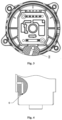
FIG. 1 is a schematic structural diagram of an oil pump gas-exhaust mechanism for an automatic transmission according to an embodiment of the present application; -
FIG. 2 is a schematic diagram of a distance from an outlet end of a gas exhaust hole to a joint surface according to an embodiment of the present application; -
FIG. 3 is a schematic structural diagram of a gas exhaust hole according to an embodiment of the present application; and -
FIG. 4 is a schematic cross-sectional view of a gas exhaust hole according to an embodiment of the present application. - The reference numerals in the figures correspond to: 1 joint surface, 2-gas exhaust hole, 3-sensor plug-in assembly, 4-waterproof base membrane, and L-distance from an outlet end of the gas exhaust hole to the joint surface.
- To clarify the purpose, technical solutions and advantages of the present application, the present application will be further described in detail below with reference to the accompanying drawings. Apparently, the described embodiments are only part rather than all of the embodiments of the present application. All other embodiments obtained by those of ordinary skill in the art based on the embodiments of the present application without creative efforts shall fall within the scope of protection of the present application.
- In the description of the present application, unless otherwise specified and limited, the terms "connected", "connection", etc. should be understood broadly. For example, the "connection" may be a fixed connection, a detachable connection, or an integrated connection, may be a mechanical connection or an electrical connection, may be a direct connection or an indirect connection by means of an intermediate medium, or may be an internal connection of two elements or an interaction between two elements. For those of ordinary skill in the art, the specific meaning of the terms in the present application may be understood according to specific situations.
- The embodiment provides an oil pump gas-exhaust mechanism for an automatic transmission. With reference to
FIGS. 1-4 , the oil pump gas-exhaust mechanism for an automatic transmission in this embodiment includes a sensor plug-inassembly 3 and an oil pump for supplying oil to the automatic transmission; the oil pump is fixedly connected to a transmission case, the sensor plug-inassembly 3 is arranged on a housing of the oil pump, and the sensor plug-inassembly 3 is used to be electrically connected to a sensor; and agas exhaust hole 2 is provided on the sensor plug-inassembly 3, thegas exhaust hole 2 is located between the oil pump and the transmission, thegas exhaust hole 2 is an inclined hole, and thegas exhaust hole 2 is inclined upwards from an outlet end relative to a horizontal plane. - According to the oil pump gas-exhaust mechanism for an automatic transmission in this embodiment, the
gas exhaust hole 2 is provided on the sensor plug-inassembly 3, and to facilitate a hole opening design, theexhaust hole 2 is arranged as the inclined hole inclined upwards relative to a direction of the horizontal plane. On the one hand, the pressure generated during the working of the oil pump can be ensured to be discharged by means of the gas exhaust hole. On the other hand, when a vehicle is driven in a working condition involving wading or there is water splashing on the ground, the oil pump for the automatic transmission avoids an active "water retention" phenomenon due to the gravity of water droplets, so that water or other foreign matters can be prevented from splashing into the electronic oil pump when the vehicle is wading, thereby ensuring the normal working of the oil pump when the vehicle is in the working condition involving wading. - As a specific embodiment, the
gas exhaust hole 2 includes an inclined section and a vertical section successively arranged from the inside of the sensor plug-inassembly 3, where the vertical section is close to the sensor plug-inassembly 3 and is perpendicular to the horizontal plane, and the inclined section is inclined upwards from the outlet end relative to the horizontal plane. - As a specific embodiment, with continued reference to
FIG. 2 , the oil pump has a joint surface 1 that is joined with the transmission case. To prevent a foreign matter, especially a large foreign matter, from entering thegas exhaust hole 2 and blocking thegas exhaust hole 2, a distance L from the outlet end of thegas exhaust hole 2 to the joint surface 1 is a preset distance, and specifically, the preset distance may be 2 mm to 5 mm. - It should be noted that, in some other embodiments, the distance from the
gas exhaust hole 2 to the joint surface 1 may further be adjusted based on a traveling condition of the vehicle, as long as the same function can be achieved. - As a specific embodiment, a waterproof base membrane 4 is further included, where the waterproof base membrane 4 has both waterproof and gas-permeable functions, and the waterproof base membrane 4 seals one end of the
gas exhaust hole 2 close to the inside of the sensor plug-inassembly 3. - As a specific embodiment, the waterproof base membrane 4 is provided inside the sensor plug-in
assembly 3, that is, the waterproof base membrane 4 seals an end portion of the vertical section located at the sensor plug-inassembly 3. The waterproof base membrane 4 arranged at a hole port inside the sensor plug-inassembly 3 ensures that heat generated by the working of the oil pump can be discharged, and a situation in which water is forced to flow back into the oil pump when undergoing serious wading can also be avoided, so that the inclinedgas exhaust hole 2 and the waterproof base membrane 4 achieve a double protection effect for the oil pump when the vehicle is in a traveling condition involving serious wading, enabling the oil pump to always maintain optimal performance under a severe traveling condition of an automobile. - As a specific embodiment, the waterproof base membrane 4 is fixed to the inside of the sensor plug-in
assembly 3 in a bonding manner. The connection manner is simple, stable, and reliable, and is convenient for mounting, disassembly, and replacement. - It should be noted that, in some other embodiments, the waterproof base membrane 4 may further be fixed inside the sensor plug-in
assembly 3 in another connection manner, as long as the same function can be achieved. - As a specific embodiment, the joint surface 1 of the oil pump is positioned on the transmission case by means of a pin hole, and is fixedly connected to the transmission case by means of a bolt. The connection manner is simple and reliable, and is easy to assemble.
- As a specific embodiment, the oil pump is an internal gear pump, including an external gear, an internal gear, a crescent-shaped diaphragm, and a pump housing, where the external gear and the internal gear are both arranged in a cavity inside the pump housing, the external gear is a driving gear, the internal gear is a driven gear, and the crescent-shaped diaphragm separates the external gear from the internal gear.
- In some other embodiments, the oil pump further includes an oil inlet and an oil outlet, where the oil inlet is used to suck hydraulic oil, and the oil outlet is used to discharge the hydraulic oil.
- The embodiment of the present application further provides an automatic transmission including the oil pump gas-exhaust mechanism for an automatic transmission.
- Accordingly, the embodiment of the present application further provides a vehicle including the automatic transmission.
- The embodiments of the present application have the following beneficial effects:
- 1. according to the oil pump gas-exhaust mechanism for an automatic transmission, and the automatic transmission and the vehicle of the present application, the gas exhaust hole is provided on the sensor plug-in assembly, and the exhaust hole is arranged as an inclined hole inclined upwards relative to the ground direction. On the one hand, the pressure generated during the working of the oil pump can be ensured to be discharged by means of the gas exhaust hole. On the other hand, when the vehicle is driven in a working condition involving wading or there is water splashing on the ground, the oil pump for the automatic transmission avoids an active "water retention" phenomenon due to the gravity of water droplets, so that water or other foreign matters can be prevented from splashing into the electronic oil pump when the vehicle is wading, thereby ensuring the normal working of the oil pump when the vehicle is in the working condition involving wading; and
- 2. according to the oil pump gas-exhaust mechanism for an automatic transmission, and the automatic transmission and the vehicle of the present application, the waterproof base membrane arranged at a hole port inside the sensor plug-in assembly ensures that heat generated by the working of the oil pump can be discharged, and a situation in which water is forced to flow back into the electronic oil pump when undergoing serious wading can also be avoided, so that the inclined gas exhaust hole and the waterproof base membrane achieve a double protection effect for the electronic oil pump when the vehicle is in a traveling condition involving serious wading.
- The described above are the preferred embodiments of the present application. It should be pointed out that, for those of ordinary skill in the art, a plurality of improvements and modifications may also be made without departing from the principles of the present application, and these improvements and modifications may also be regarded to be the scope of protection of the present application.
Claims (10)
- An oil pump gas-exhaust mechanism for an automatic transmission, the oil pump gas-exhaust mechanism comprising a sensor plug-in assembly (3) and an oil pump for supplying oil to the automatic transmission,wherein the oil pump is fixedly connected to a transmission case, the sensor plug-in assembly (3) is arranged on a housing of the oil pump, the sensor plug-in assembly (3) is located between the oil pump and the transmission, the sensor plug-in assembly (3) is configured to be electrically connected to a sensor, anda gas exhaust hole (2) is provided on the sensor plug-in assembly (3), and the gas exhaust hole (2) is inclined upwards from an outlet end relative to a horizontal plane.
- The oil pump gas-exhaust mechanism for an automatic transmission according to claim 1, wherein the gas exhaust hole (2) comprises a vertical section and an inclined section successively arranged from the inside of the sensor plug-in assembly (3), the vertical section is perpendicular to the horizontal plane, and the inclined section is inclined upwards from the outlet end relative to the horizontal plane.
- The oil pump gas-exhaust mechanism for an automatic transmission according to claim 1, wherein the oil pump has a joint surface (1) joined with the transmission case, and a distance from the outlet end of the gas exhaust hole (2) to the joint surface (1) is a preset distance.
- The oil pump gas-exhaust mechanism for an automatic transmission according to claim 1, wherein a waterproof base membrane (4) is further comprised, wherein the waterproof base membrane (4) is provided inside the sensor plug-in assembly (3), and the waterproof base membrane (4) seals one end of the gas exhaust hole (2) close to the inside of the sensor plug-in assembly (3).
- The oil pump gas-exhaust mechanism for an automatic transmission according to claim 4, wherein the waterproof base membrane (4) is fixed to the inside of the sensor plug-in assembly (3) in a bonding manner.
- The oil pump gas-exhaust mechanism for an automatic transmission according to claim 3, wherein the joint surface (1) is positioned on the transmission case by means of a pin hole, and is fixedly connected to the transmission case by means of a bolt.
- The oil pump gas-exhaust mechanism for an automatic transmission according to claim 1, wherein the oil pump is an internal gear pump, comprising an external gear, an internal gear, a crescent-shaped diaphragm, and a pump housing, wherein the external gear and the internal gear are both arranged in a cavity inside the pump housing, the external gear is a driving gear, the internal gear is a driven gear, and the crescent-shaped diaphragm separates the external gear from the internal gear.
- The oil pump gas-exhaust mechanism for an automatic transmission according to claim 1, wherein the oil pump further comprises an oil inlet and an oil outlet, the oil inlet being used to suck hydraulic oil, and the oil outlet being used to discharge the hydraulic oil.
- An automatic transmission, comprising the oil pump gas-exhaust mechanism for an automatic transmission according to any one of claims 1-8.
- A vehicle, comprising the automatic transmission of claim 9.
Applications Claiming Priority (1)
| Application Number | Priority Date | Filing Date | Title |
|---|---|---|---|
| PCT/CN2020/096648 WO2021253297A1 (en) | 2020-06-17 | 2020-06-17 | Oil pump gas-exhaust mechanism for automatic transmission, and automatic transmission and vehicle |
Publications (3)
| Publication Number | Publication Date |
|---|---|
| EP4144991A1 true EP4144991A1 (en) | 2023-03-08 |
| EP4144991A4 EP4144991A4 (en) | 2023-06-14 |
| EP4144991B1 EP4144991B1 (en) | 2023-11-29 |
Family
ID=79268852
Family Applications (1)
| Application Number | Title | Priority Date | Filing Date |
|---|---|---|---|
| EP20941421.8A Active EP4144991B1 (en) | 2020-06-17 | 2020-06-17 | Automatic transmission and vehicle |
Country Status (3)
| Country | Link |
|---|---|
| EP (1) | EP4144991B1 (en) |
| CN (1) | CN115280015B (en) |
| WO (1) | WO2021253297A1 (en) |
Family Cites Families (12)
| Publication number | Priority date | Publication date | Assignee | Title |
|---|---|---|---|---|
| JPS63246557A (en) * | 1987-03-31 | 1988-10-13 | Nissan Motor Co Ltd | Oil pump of automatic transmission |
| JP3576370B2 (en) * | 1998-03-20 | 2004-10-13 | 川崎重工業株式会社 | Oil pump |
| US6227333B1 (en) * | 1999-06-24 | 2001-05-08 | Zf Meritor, Llc | Transmission housing with integral pump assembly |
| JP3953828B2 (en) * | 2002-02-20 | 2007-08-08 | 株式会社日立製作所 | Oil pump |
| DE112007001716T5 (en) * | 2006-11-24 | 2009-05-07 | Aisin AW Co., Ltd., Anjo | Automatic transmission control unit and automatic transmission with this |
| DE102007004964B4 (en) * | 2007-01-26 | 2012-05-16 | Sew-Eurodrive Gmbh & Co. Kg | Transmission with lubricating oil pump and gearbox series |
| JP5214644B2 (en) * | 2010-02-09 | 2013-06-19 | ジヤトコ株式会社 | Air vent structure of oil pump for automatic transmission |
| CN203308705U (en) * | 2013-06-07 | 2013-11-27 | 北京航空航天大学 | Permanent magnet servo inner engaged gear type electro-hydraulic pump |
| EP3434900A4 (en) * | 2016-03-22 | 2019-04-03 | Jatco Ltd. | Air vent structure of oil pump for automatic transmission, and method for assembling air vent structure |
| CN107448382A (en) * | 2016-05-31 | 2017-12-08 | 内蒙古欧意德发动机有限公司 | Gear box oil pump and gearbox |
| CN207989599U (en) * | 2018-03-27 | 2018-10-19 | 江铃控股有限公司 | Automatic gearbox |
| CN208703097U (en) * | 2018-07-13 | 2019-04-05 | 一汽解放汽车有限公司 | A commercial vehicle mechanical automatic transmission assembly |
-
2020
- 2020-06-17 WO PCT/CN2020/096648 patent/WO2021253297A1/en not_active Ceased
- 2020-06-17 EP EP20941421.8A patent/EP4144991B1/en active Active
- 2020-06-17 CN CN202080098422.0A patent/CN115280015B/en active Active
Also Published As
| Publication number | Publication date |
|---|---|
| EP4144991B1 (en) | 2023-11-29 |
| EP4144991A4 (en) | 2023-06-14 |
| WO2021253297A1 (en) | 2021-12-23 |
| CN115280015B (en) | 2023-07-18 |
| CN115280015A (en) | 2022-11-01 |
Similar Documents
| Publication | Publication Date | Title |
|---|---|---|
| US10371254B2 (en) | Vehicle drive device | |
| US10190671B2 (en) | Vehicle drive device | |
| JP5089729B2 (en) | Oil pump device | |
| CN108979779B (en) | An engine lubricating oil circulation system | |
| EP4144991B1 (en) | Automatic transmission and vehicle | |
| JP2760693B2 (en) | Oil storage structure of internal combustion engine | |
| CN215890441U (en) | Electric oil pump with oil suction filter | |
| CN207230133U (en) | A kind of rotor-type oil pump for reducing noise | |
| CN209839650U (en) | Single-support rotor pump with idle gear | |
| CN112524027A (en) | Combined oil seal structure and air compressor | |
| CN215170750U (en) | Two-stage screw compressor with novel structure | |
| CN217602912U (en) | Pump Covers, Pump Units and Vehicles | |
| JP2578284B2 (en) | Oil pump mounting structure for internal combustion engine | |
| CN215860473U (en) | Diesel engine structure with double gear chambers | |
| CN212456228U (en) | Large-flow double-section pump | |
| CN212429209U (en) | High-lift water pumping device capable of reducing vibration | |
| CN111998056A (en) | Self-lubricating planet wheel derailleur auxiliary tank | |
| CN216242166U (en) | Oil supply system for tractor transmission system | |
| CN215807802U (en) | DCT oil pump structure and vehicle | |
| CN218216999U (en) | Low-noise small-sized direct-current speed reduction motor | |
| CN219549559U (en) | Gearbox side cap and gearbox | |
| CN217582484U (en) | Miniature gear pump for miniature turbojet engine | |
| CN218818027U (en) | Gearbox of crawler tractor | |
| CN220320277U (en) | A motorcycle engine main and auxiliary shaft mechanism | |
| CN217539559U (en) | Input lubricating structure of orthogonal speed reducer |
Legal Events
| Date | Code | Title | Description |
|---|---|---|---|
| STAA | Information on the status of an ep patent application or granted ep patent |
Free format text: STATUS: THE INTERNATIONAL PUBLICATION HAS BEEN MADE |
|
| PUAI | Public reference made under article 153(3) epc to a published international application that has entered the european phase |
Free format text: ORIGINAL CODE: 0009012 |
|
| STAA | Information on the status of an ep patent application or granted ep patent |
Free format text: STATUS: REQUEST FOR EXAMINATION WAS MADE |
|
| 17P | Request for examination filed |
Effective date: 20221130 |
|
| AK | Designated contracting states |
Kind code of ref document: A1 Designated state(s): AL AT BE BG CH CY CZ DE DK EE ES FI FR GB GR HR HU IE IS IT LI LT LU LV MC MK MT NL NO PL PT RO RS SE SI SK SM TR |
|
| STAA | Information on the status of an ep patent application or granted ep patent |
Free format text: STATUS: EXAMINATION IS IN PROGRESS |
|
| A4 | Supplementary search report drawn up and despatched |
Effective date: 20230517 |
|
| RIC1 | Information provided on ipc code assigned before grant |
Ipc: F16H 57/04 20100101ALI20230511BHEP Ipc: F04C 2/08 20060101ALI20230511BHEP Ipc: F04C 15/00 20060101ALI20230511BHEP Ipc: F04C 11/00 20060101AFI20230511BHEP |
|
| 17Q | First examination report despatched |
Effective date: 20230530 |
|
| GRAP | Despatch of communication of intention to grant a patent |
Free format text: ORIGINAL CODE: EPIDOSNIGR1 |
|
| STAA | Information on the status of an ep patent application or granted ep patent |
Free format text: STATUS: GRANT OF PATENT IS INTENDED |
|
| RIC1 | Information provided on ipc code assigned before grant |
Ipc: F04C 14/28 20060101ALI20230809BHEP Ipc: F04C 2/10 20060101ALI20230809BHEP Ipc: F16H 57/04 20100101ALI20230809BHEP Ipc: F04C 2/08 20060101ALI20230809BHEP Ipc: F04C 15/00 20060101ALI20230809BHEP Ipc: F04C 11/00 20060101AFI20230809BHEP |
|
| DAV | Request for validation of the european patent (deleted) | ||
| DAX | Request for extension of the european patent (deleted) | ||
| INTG | Intention to grant announced |
Effective date: 20230829 |
|
| GRAS | Grant fee paid |
Free format text: ORIGINAL CODE: EPIDOSNIGR3 |
|
| GRAA | (expected) grant |
Free format text: ORIGINAL CODE: 0009210 |
|
| STAA | Information on the status of an ep patent application or granted ep patent |
Free format text: STATUS: THE PATENT HAS BEEN GRANTED |
|
| AK | Designated contracting states |
Kind code of ref document: B1 Designated state(s): AL AT BE BG CH CY CZ DE DK EE ES FI FR GB GR HR HU IE IS IT LI LT LU LV MC MK MT NL NO PL PT RO RS SE SI SK SM TR |
|
| REG | Reference to a national code |
Ref country code: GB Ref legal event code: FG4D |
|
| REG | Reference to a national code |
Ref country code: CH Ref legal event code: EP |
|
| REG | Reference to a national code |
Ref country code: DE Ref legal event code: R096 Ref document number: 602020022134 Country of ref document: DE |
|
| REG | Reference to a national code |
Ref country code: IE Ref legal event code: FG4D |
|
| REG | Reference to a national code |
Ref country code: SE Ref legal event code: TRGR |
|
| REG | Reference to a national code |
Ref country code: LT Ref legal event code: MG9D |
|
| REG | Reference to a national code |
Ref country code: NL Ref legal event code: MP Effective date: 20231129 |
|
| PG25 | Lapsed in a contracting state [announced via postgrant information from national office to epo] |
Ref country code: GR Free format text: LAPSE BECAUSE OF FAILURE TO SUBMIT A TRANSLATION OF THE DESCRIPTION OR TO PAY THE FEE WITHIN THE PRESCRIBED TIME-LIMIT Effective date: 20240301 |
|
| PG25 | Lapsed in a contracting state [announced via postgrant information from national office to epo] |
Ref country code: IS Free format text: LAPSE BECAUSE OF FAILURE TO SUBMIT A TRANSLATION OF THE DESCRIPTION OR TO PAY THE FEE WITHIN THE PRESCRIBED TIME-LIMIT Effective date: 20240329 |
|
| PG25 | Lapsed in a contracting state [announced via postgrant information from national office to epo] |
Ref country code: LT Free format text: LAPSE BECAUSE OF FAILURE TO SUBMIT A TRANSLATION OF THE DESCRIPTION OR TO PAY THE FEE WITHIN THE PRESCRIBED TIME-LIMIT Effective date: 20231129 |
|
| PG25 | Lapsed in a contracting state [announced via postgrant information from national office to epo] |
Ref country code: ES Free format text: LAPSE BECAUSE OF FAILURE TO SUBMIT A TRANSLATION OF THE DESCRIPTION OR TO PAY THE FEE WITHIN THE PRESCRIBED TIME-LIMIT Effective date: 20231129 |
|
| PG25 | Lapsed in a contracting state [announced via postgrant information from national office to epo] |
Ref country code: LT Free format text: LAPSE BECAUSE OF FAILURE TO SUBMIT A TRANSLATION OF THE DESCRIPTION OR TO PAY THE FEE WITHIN THE PRESCRIBED TIME-LIMIT Effective date: 20231129 Ref country code: IS Free format text: LAPSE BECAUSE OF FAILURE TO SUBMIT A TRANSLATION OF THE DESCRIPTION OR TO PAY THE FEE WITHIN THE PRESCRIBED TIME-LIMIT Effective date: 20240329 Ref country code: GR Free format text: LAPSE BECAUSE OF FAILURE TO SUBMIT A TRANSLATION OF THE DESCRIPTION OR TO PAY THE FEE WITHIN THE PRESCRIBED TIME-LIMIT Effective date: 20240301 Ref country code: ES Free format text: LAPSE BECAUSE OF FAILURE TO SUBMIT A TRANSLATION OF THE DESCRIPTION OR TO PAY THE FEE WITHIN THE PRESCRIBED TIME-LIMIT Effective date: 20231129 Ref country code: BG Free format text: LAPSE BECAUSE OF FAILURE TO SUBMIT A TRANSLATION OF THE DESCRIPTION OR TO PAY THE FEE WITHIN THE PRESCRIBED TIME-LIMIT Effective date: 20240229 |
|
| REG | Reference to a national code |
Ref country code: AT Ref legal event code: MK05 Ref document number: 1636379 Country of ref document: AT Kind code of ref document: T Effective date: 20231129 |
|
| PG25 | Lapsed in a contracting state [announced via postgrant information from national office to epo] |
Ref country code: NL Free format text: LAPSE BECAUSE OF FAILURE TO SUBMIT A TRANSLATION OF THE DESCRIPTION OR TO PAY THE FEE WITHIN THE PRESCRIBED TIME-LIMIT Effective date: 20231129 |
|
| PG25 | Lapsed in a contracting state [announced via postgrant information from national office to epo] |
Ref country code: RS Free format text: LAPSE BECAUSE OF FAILURE TO SUBMIT A TRANSLATION OF THE DESCRIPTION OR TO PAY THE FEE WITHIN THE PRESCRIBED TIME-LIMIT Effective date: 20231129 Ref country code: PL Free format text: LAPSE BECAUSE OF FAILURE TO SUBMIT A TRANSLATION OF THE DESCRIPTION OR TO PAY THE FEE WITHIN THE PRESCRIBED TIME-LIMIT Effective date: 20231129 Ref country code: NO Free format text: LAPSE BECAUSE OF FAILURE TO SUBMIT A TRANSLATION OF THE DESCRIPTION OR TO PAY THE FEE WITHIN THE PRESCRIBED TIME-LIMIT Effective date: 20240229 Ref country code: NL Free format text: LAPSE BECAUSE OF FAILURE TO SUBMIT A TRANSLATION OF THE DESCRIPTION OR TO PAY THE FEE WITHIN THE PRESCRIBED TIME-LIMIT Effective date: 20231129 Ref country code: LV Free format text: LAPSE BECAUSE OF FAILURE TO SUBMIT A TRANSLATION OF THE DESCRIPTION OR TO PAY THE FEE WITHIN THE PRESCRIBED TIME-LIMIT Effective date: 20231129 Ref country code: HR Free format text: LAPSE BECAUSE OF FAILURE TO SUBMIT A TRANSLATION OF THE DESCRIPTION OR TO PAY THE FEE WITHIN THE PRESCRIBED TIME-LIMIT Effective date: 20231129 |
|
| PG25 | Lapsed in a contracting state [announced via postgrant information from national office to epo] |
Ref country code: DK Free format text: LAPSE BECAUSE OF FAILURE TO SUBMIT A TRANSLATION OF THE DESCRIPTION OR TO PAY THE FEE WITHIN THE PRESCRIBED TIME-LIMIT Effective date: 20231129 |
|
| PG25 | Lapsed in a contracting state [announced via postgrant information from national office to epo] |
Ref country code: CZ Free format text: LAPSE BECAUSE OF FAILURE TO SUBMIT A TRANSLATION OF THE DESCRIPTION OR TO PAY THE FEE WITHIN THE PRESCRIBED TIME-LIMIT Effective date: 20231129 Ref country code: AT Free format text: LAPSE BECAUSE OF FAILURE TO SUBMIT A TRANSLATION OF THE DESCRIPTION OR TO PAY THE FEE WITHIN THE PRESCRIBED TIME-LIMIT Effective date: 20231129 |
|
| PG25 | Lapsed in a contracting state [announced via postgrant information from national office to epo] |
Ref country code: SK Free format text: LAPSE BECAUSE OF FAILURE TO SUBMIT A TRANSLATION OF THE DESCRIPTION OR TO PAY THE FEE WITHIN THE PRESCRIBED TIME-LIMIT Effective date: 20231129 |
|
| PG25 | Lapsed in a contracting state [announced via postgrant information from national office to epo] |
Ref country code: SM Free format text: LAPSE BECAUSE OF FAILURE TO SUBMIT A TRANSLATION OF THE DESCRIPTION OR TO PAY THE FEE WITHIN THE PRESCRIBED TIME-LIMIT Effective date: 20231129 Ref country code: SK Free format text: LAPSE BECAUSE OF FAILURE TO SUBMIT A TRANSLATION OF THE DESCRIPTION OR TO PAY THE FEE WITHIN THE PRESCRIBED TIME-LIMIT Effective date: 20231129 Ref country code: RO Free format text: LAPSE BECAUSE OF FAILURE TO SUBMIT A TRANSLATION OF THE DESCRIPTION OR TO PAY THE FEE WITHIN THE PRESCRIBED TIME-LIMIT Effective date: 20231129 Ref country code: IT Free format text: LAPSE BECAUSE OF FAILURE TO SUBMIT A TRANSLATION OF THE DESCRIPTION OR TO PAY THE FEE WITHIN THE PRESCRIBED TIME-LIMIT Effective date: 20231129 Ref country code: EE Free format text: LAPSE BECAUSE OF FAILURE TO SUBMIT A TRANSLATION OF THE DESCRIPTION OR TO PAY THE FEE WITHIN THE PRESCRIBED TIME-LIMIT Effective date: 20231129 Ref country code: DK Free format text: LAPSE BECAUSE OF FAILURE TO SUBMIT A TRANSLATION OF THE DESCRIPTION OR TO PAY THE FEE WITHIN THE PRESCRIBED TIME-LIMIT Effective date: 20231129 Ref country code: CZ Free format text: LAPSE BECAUSE OF FAILURE TO SUBMIT A TRANSLATION OF THE DESCRIPTION OR TO PAY THE FEE WITHIN THE PRESCRIBED TIME-LIMIT Effective date: 20231129 Ref country code: AT Free format text: LAPSE BECAUSE OF FAILURE TO SUBMIT A TRANSLATION OF THE DESCRIPTION OR TO PAY THE FEE WITHIN THE PRESCRIBED TIME-LIMIT Effective date: 20231129 |
|
| PG25 | Lapsed in a contracting state [announced via postgrant information from national office to epo] |
Ref country code: PT Free format text: LAPSE BECAUSE OF FAILURE TO SUBMIT A TRANSLATION OF THE DESCRIPTION OR TO PAY THE FEE WITHIN THE PRESCRIBED TIME-LIMIT Effective date: 20240401 |
|
| PG25 | Lapsed in a contracting state [announced via postgrant information from national office to epo] |
Ref country code: PT Free format text: LAPSE BECAUSE OF FAILURE TO SUBMIT A TRANSLATION OF THE DESCRIPTION OR TO PAY THE FEE WITHIN THE PRESCRIBED TIME-LIMIT Effective date: 20240401 |
|
| REG | Reference to a national code |
Ref country code: DE Ref legal event code: R097 Ref document number: 602020022134 Country of ref document: DE |
|
| PLBE | No opposition filed within time limit |
Free format text: ORIGINAL CODE: 0009261 |
|
| STAA | Information on the status of an ep patent application or granted ep patent |
Free format text: STATUS: NO OPPOSITION FILED WITHIN TIME LIMIT |
|
| PG25 | Lapsed in a contracting state [announced via postgrant information from national office to epo] |
Ref country code: SI Free format text: LAPSE BECAUSE OF FAILURE TO SUBMIT A TRANSLATION OF THE DESCRIPTION OR TO PAY THE FEE WITHIN THE PRESCRIBED TIME-LIMIT Effective date: 20231129 |
|
| PG25 | Lapsed in a contracting state [announced via postgrant information from national office to epo] |
Ref country code: SI Free format text: LAPSE BECAUSE OF FAILURE TO SUBMIT A TRANSLATION OF THE DESCRIPTION OR TO PAY THE FEE WITHIN THE PRESCRIBED TIME-LIMIT Effective date: 20231129 |
|
| 26N | No opposition filed |
Effective date: 20240830 |
|
| PG25 | Lapsed in a contracting state [announced via postgrant information from national office to epo] |
Ref country code: MC Free format text: LAPSE BECAUSE OF FAILURE TO SUBMIT A TRANSLATION OF THE DESCRIPTION OR TO PAY THE FEE WITHIN THE PRESCRIBED TIME-LIMIT Effective date: 20231129 |
|
| REG | Reference to a national code |
Ref country code: CH Ref legal event code: PL |
|
| PG25 | Lapsed in a contracting state [announced via postgrant information from national office to epo] |
Ref country code: LU Free format text: LAPSE BECAUSE OF NON-PAYMENT OF DUE FEES Effective date: 20240617 |
|
| GBPC | Gb: european patent ceased through non-payment of renewal fee |
Effective date: 20240617 |
|
| PGFP | Annual fee paid to national office [announced via postgrant information from national office to epo] |
Ref country code: SE Payment date: 20250312 Year of fee payment: 6 |
|
| PG25 | Lapsed in a contracting state [announced via postgrant information from national office to epo] |
Ref country code: IE Free format text: LAPSE BECAUSE OF NON-PAYMENT OF DUE FEES Effective date: 20240617 |
|
| PG25 | Lapsed in a contracting state [announced via postgrant information from national office to epo] |
Ref country code: CH Free format text: LAPSE BECAUSE OF NON-PAYMENT OF DUE FEES Effective date: 20240630 |
|
| PG25 | Lapsed in a contracting state [announced via postgrant information from national office to epo] |
Ref country code: FR Free format text: LAPSE BECAUSE OF NON-PAYMENT OF DUE FEES Effective date: 20240630 |
|
| PG25 | Lapsed in a contracting state [announced via postgrant information from national office to epo] |
Ref country code: GB Free format text: LAPSE BECAUSE OF NON-PAYMENT OF DUE FEES Effective date: 20240617 |
|
| PGFP | Annual fee paid to national office [announced via postgrant information from national office to epo] |
Ref country code: DE Payment date: 20250618 Year of fee payment: 6 |
|
| PGFP | Annual fee paid to national office [announced via postgrant information from national office to epo] |
Ref country code: BE Payment date: 20250617 Year of fee payment: 6 |
|
| PG25 | Lapsed in a contracting state [announced via postgrant information from national office to epo] |
Ref country code: FI Free format text: LAPSE BECAUSE OF FAILURE TO SUBMIT A TRANSLATION OF THE DESCRIPTION OR TO PAY THE FEE WITHIN THE PRESCRIBED TIME-LIMIT Effective date: 20231129 |
|
| PG25 | Lapsed in a contracting state [announced via postgrant information from national office to epo] |
Ref country code: CY Free format text: LAPSE BECAUSE OF FAILURE TO SUBMIT A TRANSLATION OF THE DESCRIPTION OR TO PAY THE FEE WITHIN THE PRESCRIBED TIME-LIMIT; INVALID AB INITIO Effective date: 20200617 |
|
| PG25 | Lapsed in a contracting state [announced via postgrant information from national office to epo] |
Ref country code: HU Free format text: LAPSE BECAUSE OF FAILURE TO SUBMIT A TRANSLATION OF THE DESCRIPTION OR TO PAY THE FEE WITHIN THE PRESCRIBED TIME-LIMIT; INVALID AB INITIO Effective date: 20200617 |