EP4144976A1 - Engine controlling method and engine system - Google Patents
Engine controlling method and engine system Download PDFInfo
- Publication number
- EP4144976A1 EP4144976A1 EP22187392.0A EP22187392A EP4144976A1 EP 4144976 A1 EP4144976 A1 EP 4144976A1 EP 22187392 A EP22187392 A EP 22187392A EP 4144976 A1 EP4144976 A1 EP 4144976A1
- Authority
- EP
- European Patent Office
- Prior art keywords
- fuel
- cylinder
- engine
- controller
- pressure value
- Prior art date
- Legal status (The legal status is an assumption and is not a legal conclusion. Google has not performed a legal analysis and makes no representation as to the accuracy of the status listed.)
- Granted
Links
Images
Classifications
-
- F—MECHANICAL ENGINEERING; LIGHTING; HEATING; WEAPONS; BLASTING
- F02—COMBUSTION ENGINES; HOT-GAS OR COMBUSTION-PRODUCT ENGINE PLANTS
- F02D—CONTROLLING COMBUSTION ENGINES
- F02D41/00—Electrical control of supply of combustible mixture or its constituents
- F02D41/30—Controlling fuel injection
- F02D41/38—Controlling fuel injection of the high pressure type
- F02D41/40—Controlling fuel injection of the high pressure type with means for controlling injection timing or duration
- F02D41/401—Controlling injection timing
-
- F—MECHANICAL ENGINEERING; LIGHTING; HEATING; WEAPONS; BLASTING
- F02—COMBUSTION ENGINES; HOT-GAS OR COMBUSTION-PRODUCT ENGINE PLANTS
- F02D—CONTROLLING COMBUSTION ENGINES
- F02D13/00—Controlling the engine output power by varying inlet or exhaust valve operating characteristics, e.g. timing
- F02D13/02—Controlling the engine output power by varying inlet or exhaust valve operating characteristics, e.g. timing during engine operation
- F02D13/0223—Variable control of the intake valves only
- F02D13/0234—Variable control of the intake valves only changing the valve timing only
-
- F—MECHANICAL ENGINEERING; LIGHTING; HEATING; WEAPONS; BLASTING
- F02—COMBUSTION ENGINES; HOT-GAS OR COMBUSTION-PRODUCT ENGINE PLANTS
- F02D—CONTROLLING COMBUSTION ENGINES
- F02D35/00—Controlling engines, dependent on conditions exterior or interior to engines, not otherwise provided for
- F02D35/02—Controlling engines, dependent on conditions exterior or interior to engines, not otherwise provided for on interior conditions
- F02D35/023—Controlling engines, dependent on conditions exterior or interior to engines, not otherwise provided for on interior conditions by determining the cylinder pressure
-
- F—MECHANICAL ENGINEERING; LIGHTING; HEATING; WEAPONS; BLASTING
- F02—COMBUSTION ENGINES; HOT-GAS OR COMBUSTION-PRODUCT ENGINE PLANTS
- F02D—CONTROLLING COMBUSTION ENGINES
- F02D35/00—Controlling engines, dependent on conditions exterior or interior to engines, not otherwise provided for
- F02D35/02—Controlling engines, dependent on conditions exterior or interior to engines, not otherwise provided for on interior conditions
- F02D35/028—Controlling engines, dependent on conditions exterior or interior to engines, not otherwise provided for on interior conditions by determining the combustion timing or phasing
-
- F—MECHANICAL ENGINEERING; LIGHTING; HEATING; WEAPONS; BLASTING
- F02—COMBUSTION ENGINES; HOT-GAS OR COMBUSTION-PRODUCT ENGINE PLANTS
- F02D—CONTROLLING COMBUSTION ENGINES
- F02D41/00—Electrical control of supply of combustible mixture or its constituents
- F02D41/0025—Controlling engines characterised by use of non-liquid fuels, pluralities of fuels, or non-fuel substances added to the combustible mixtures
-
- F—MECHANICAL ENGINEERING; LIGHTING; HEATING; WEAPONS; BLASTING
- F02—COMBUSTION ENGINES; HOT-GAS OR COMBUSTION-PRODUCT ENGINE PLANTS
- F02D—CONTROLLING COMBUSTION ENGINES
- F02D41/00—Electrical control of supply of combustible mixture or its constituents
- F02D41/009—Electrical control of supply of combustible mixture or its constituents using means for generating position or synchronisation signals
-
- F—MECHANICAL ENGINEERING; LIGHTING; HEATING; WEAPONS; BLASTING
- F02—COMBUSTION ENGINES; HOT-GAS OR COMBUSTION-PRODUCT ENGINE PLANTS
- F02D—CONTROLLING COMBUSTION ENGINES
- F02D41/00—Electrical control of supply of combustible mixture or its constituents
- F02D41/02—Circuit arrangements for generating control signals
- F02D41/04—Introducing corrections for particular operating conditions
- F02D41/06—Introducing corrections for particular operating conditions for engine starting or warming up
- F02D41/062—Introducing corrections for particular operating conditions for engine starting or warming up for starting
-
- F—MECHANICAL ENGINEERING; LIGHTING; HEATING; WEAPONS; BLASTING
- F02—COMBUSTION ENGINES; HOT-GAS OR COMBUSTION-PRODUCT ENGINE PLANTS
- F02D—CONTROLLING COMBUSTION ENGINES
- F02D41/00—Electrical control of supply of combustible mixture or its constituents
- F02D41/24—Electrical control of supply of combustible mixture or its constituents characterised by the use of digital means
- F02D41/2406—Electrical control of supply of combustible mixture or its constituents characterised by the use of digital means using essentially read only memories
- F02D41/2425—Particular ways of programming the data
- F02D41/2429—Methods of calibrating or learning
- F02D41/2477—Methods of calibrating or learning characterised by the method used for learning
-
- F—MECHANICAL ENGINEERING; LIGHTING; HEATING; WEAPONS; BLASTING
- F02—COMBUSTION ENGINES; HOT-GAS OR COMBUSTION-PRODUCT ENGINE PLANTS
- F02D—CONTROLLING COMBUSTION ENGINES
- F02D41/00—Electrical control of supply of combustible mixture or its constituents
- F02D41/30—Controlling fuel injection
- F02D41/38—Controlling fuel injection of the high pressure type
- F02D41/40—Controlling fuel injection of the high pressure type with means for controlling injection timing or duration
-
- F—MECHANICAL ENGINEERING; LIGHTING; HEATING; WEAPONS; BLASTING
- F02—COMBUSTION ENGINES; HOT-GAS OR COMBUSTION-PRODUCT ENGINE PLANTS
- F02D—CONTROLLING COMBUSTION ENGINES
- F02D41/00—Electrical control of supply of combustible mixture or its constituents
- F02D41/30—Controlling fuel injection
- F02D41/38—Controlling fuel injection of the high pressure type
- F02D2041/389—Controlling fuel injection of the high pressure type for injecting directly into the cylinder
-
- F—MECHANICAL ENGINEERING; LIGHTING; HEATING; WEAPONS; BLASTING
- F02—COMBUSTION ENGINES; HOT-GAS OR COMBUSTION-PRODUCT ENGINE PLANTS
- F02D—CONTROLLING COMBUSTION ENGINES
- F02D2200/00—Input parameters for engine control
- F02D2200/02—Input parameters for engine control the parameters being related to the engine
- F02D2200/024—Fluid pressure of lubricating oil or working fluid
-
- F—MECHANICAL ENGINEERING; LIGHTING; HEATING; WEAPONS; BLASTING
- F02—COMBUSTION ENGINES; HOT-GAS OR COMBUSTION-PRODUCT ENGINE PLANTS
- F02D—CONTROLLING COMBUSTION ENGINES
- F02D2200/00—Input parameters for engine control
- F02D2200/02—Input parameters for engine control the parameters being related to the engine
- F02D2200/06—Fuel or fuel supply system parameters
- F02D2200/0611—Fuel type, fuel composition or fuel quality
- F02D2200/0612—Fuel type, fuel composition or fuel quality determined by estimation
-
- Y—GENERAL TAGGING OF NEW TECHNOLOGICAL DEVELOPMENTS; GENERAL TAGGING OF CROSS-SECTIONAL TECHNOLOGIES SPANNING OVER SEVERAL SECTIONS OF THE IPC; TECHNICAL SUBJECTS COVERED BY FORMER USPC CROSS-REFERENCE ART COLLECTIONS [XRACs] AND DIGESTS
- Y02—TECHNOLOGIES OR APPLICATIONS FOR MITIGATION OR ADAPTATION AGAINST CLIMATE CHANGE
- Y02T—CLIMATE CHANGE MITIGATION TECHNOLOGIES RELATED TO TRANSPORTATION
- Y02T10/00—Road transport of goods or passengers
- Y02T10/10—Internal combustion engine [ICE] based vehicles
- Y02T10/30—Use of alternative fuels, e.g. biofuels
-
- Y—GENERAL TAGGING OF NEW TECHNOLOGICAL DEVELOPMENTS; GENERAL TAGGING OF CROSS-SECTIONAL TECHNOLOGIES SPANNING OVER SEVERAL SECTIONS OF THE IPC; TECHNICAL SUBJECTS COVERED BY FORMER USPC CROSS-REFERENCE ART COLLECTIONS [XRACs] AND DIGESTS
- Y02—TECHNOLOGIES OR APPLICATIONS FOR MITIGATION OR ADAPTATION AGAINST CLIMATE CHANGE
- Y02T—CLIMATE CHANGE MITIGATION TECHNOLOGIES RELATED TO TRANSPORTATION
- Y02T10/00—Road transport of goods or passengers
- Y02T10/10—Internal combustion engine [ICE] based vehicles
- Y02T10/40—Engine management systems
Definitions
- the present disclosure relates to a method of controlling an engine and an engine system.
- JP2014-234727A discloses a technique for creating a heat release rate waveform of a low-temperature oxidation reaction, after fuel is injected into a cylinder, by setting a reaction start timing of fuel according to a period during which the fuel floats so as to be on a more advancing side (the lower temperature side of a reaction startable temperature of the low-temperature oxidation reaction) as the floating period is longer. According to this technique, the combustion state can be diagnosed with sufficient accuracy.
- a controller of the engine controls the engine by setting beforehand a fuel injection timing and a fuel injection amount which are used for optimal combustion based on the property of a standard fuel. If the property of fuel supplied to the automobile is different from the standard fuel, it may cause misfire or rapid combustion. Therefore, there is a demand of accurately determining the property of fuel supplied to the engine.
- the technique disclosed herein enables a determination of the property of fuel supplied to an engine with sufficient accuracy.
- a method of controlling an engine includes injecting, during motoring of the engine, by an injector, fuel for analysis into a cylinder at a specific timing after an intake valve of the cylinder of the engine is closed.
- the method includes outputting to a controller, by an in-cylinder pressure sensor, a signal corresponding to a pressure inside the cylinder at least at a timing when a specific crank angle period has passed from the fuel injection timing.
- the method includes determining, by the controller, a property of the fuel injected by the injector, by comparing a pressure value measured by the in-cylinder pressure sensor with a predetermined reference pressure value inside the cylinder.
- the reference pressure is measured, particularly in advance, at a timing when the specific crank angle period has passed after a standard fuel is injected into the cylinder at the specific timing.
- the controller compares a pressure value measured by the in-cylinder pressure sensor with a predetermined reference pressure value.
- the property of the fuel may be a pressure value measured by the in-cylinder pressure sensor.
- the injector injects the fuel for analysis into the cylinder during motoring of the engine.
- “motoring of the engine” may refer to a state where a crankshaft of the engine starts rotation by a drive source outside of the engine, such as a generator, an electric motor, or a starter motor.
- the motoring of the engine may correspond to a startup of the engine.
- the startup of the engine may correspond to, in the case of engine vehicles, when an ignition switch of an automobile being turned on by a person onboard, or, in the case of hybrid vehicles, when an engine is started for, for example, a demand of generating power, and satisfying a demand torque.
- intake stroke, compression stroke, expansion stroke, and exhaust stroke are performed inside the cylinder, by an external driving force.
- the injector injects the fuel for analysis into the cylinder at the specific timing during compression stroke after the intake valve is closed.
- the "fuel for analysis” may be a small amount of fuel with which a high-temperature oxidation reaction does not occur even when a piston reaches a compression top dead center.
- the "fuel for analysis” is fuel to be supplied into the cylinder in order to determine the property of the fuel.
- the pressure inside the cylinder gradually rises accompanied by the progress of compression stroke.
- the fuel injected into the cylinder results in the low-temperature oxidation reaction, through fission, atomization, evaporation, and mixing with air, according to the progress of time.
- the property of fuel for example, a ratio of specific heat and/or a gas constant of fuel
- the amount of heat released also differs. That is, since the initial chemical reaction is different in a preparatory step of the low-temperature oxidation reaction (for example, an in-cylinder gas temperature is 700 K), the amount of heat released is different.
- the initial chemical reaction is radical (alkylperoxy RO2, QOOHO2) generation by a hydrogen abstraction reaction.
- the difference in the amount of heat released causes a difference in the rate of pressure increase inside the cylinder.
- the in-cylinder pressure sensor outputs to the controller the signal corresponding to the pressure inside the cylinder at the timing when the specific crank angle period has passed from the fuel injection timing. If the fuel injected from the injector is fuel which easily generates heat, the pressure value is relatively high. On the other hand, if the fuel does not easily generate heat, the pressure value is relatively low.
- the controller may store the reference pressure value of the standard fuel in advance.
- the "standard fuel” may be, for example, fuel corresponding to K2202 (Motor Gasoline) or K2204 (Diesel Fuel) defined by Japanese Industrial Standards (JIS).
- the reference pressure value of the standard fuel is the pressure value inside the cylinder at the timing when the specific crank angle period has passed after the standard fuel is injected into the cylinder at the specific timing. Further, the controller compares the pressure value measured by the in-cylinder pressure sensor with the reference pressure value of the standard fuel.
- the fuel injected from the injector easily generates heat, which easily causes the low-temperature oxidation reaction. Therefore, this type of fuel will easily cause the high-temperature oxidation reaction under the engine operation after the startup is finished (that is, when the engine operates by the fuel injected into the cylinder being combusted, unlike the motoring). In this case, the combustion inside the cylinder tends to be rapid and combustion noise tends to increase.
- the fuel injected from the injector does not easily generate heat, which does not easily cause the low-temperature oxidation reaction. Therefore, this type of fuel does not easily cause the high-temperature oxidation reaction under the engine operation after the startup is finished, and as a result, the combustion may be slow. This may lead to a reduction in engine torque and the degradation of fuel efficiency.
- the controller compares the pressure values at the timing when the specific crank angle period has passed after the fuel injection timing, based on the rate of pressure increase inside the cylinder varying according to the heat release amount of the fuel injected into the cylinder.
- the controller can determine the property of fuel supplied to the engine with sufficient accuracy.
- the determination of the fuel property is performed during motoring of the engine. Since the high-temperature oxidation reaction of fuel does not occur under these circumstances, the controller can determine the fuel property without being influenced by heat or residual gas. Thus, the controller can determine more accurately the property of fuel supplied to the engine.
- the cylinder may be one of a plurality of cylinders, and the cylinder into which the injector injects the fuel for analysis may be the cylinder, out of the plurality of cylinders, whose the intake valve is closed first after a crankshaft of the engine starts rotation.
- the rotation speed of the crankshaft gradually increases accompanied by the progress of the engine cycle, and accordingly, the in-cylinder temperature gradually increases.
- the determination of the fuel property may be influenced by heat.
- the controller can determine the fuel property without being influenced by heat or residual gas.
- the injector may inject the fuel for analysis to each of the plurality of cylinders as a cycle of the engine progresses.
- the in-cylinder pressure sensor may output the pressure values of the plurality of cylinders.
- the controller may compare an average value of the plurality of pressure values with the reference pressure value to determine the property.
- the determination accuracy improves by the controller using the average value of the plurality of pressure values to determine the fuel property.
- the specific crank angle period may become shorter as the cycle progresses.
- the in-cylinder temperature gradually increases accompanied by the progress of the engine cycle.
- the temperature increase inside the cylinder makes the fuel injected into the cylinder more reactive, which promotes the pressure increase inside the cylinder.
- the pressure value from which the influence of the temperature increase in each of the cycles is eliminated, can be measured.
- the controller can further accurately determine the fuel property based on the plurality of pressure values.
- the specific crank angle period may correspond to a period during which the fuel injected into the cylinder from the injector achieves a low-temperature oxidation reaction through fission, atomization, evaporation, and mixing with air.
- this technique is for determining the fuel property by making use of the fact that the heat release amount in the initial chemical reaction is different.
- the in-cylinder pressure sensor can measure the pressure value to which the heat release amount in the initial chemical reaction is reflected.
- the controller can determine the fuel property with sufficient accuracy using the pressure value.
- the specific crank angle period may be set as a period until the piston inside the cylinder reaches a compression top dead center.
- the controller may correct at least one of a fuel injection amount and a close timing of the intake valve according to the property of the fuel.
- the high-temperature oxidation reaction occurs more easily, which may cause the rapid combustion.
- the fuel injected from the injector does not easily cause the low-temperature oxidation reaction, the high-temperature oxidation reaction occurs less easily, which may cause the slow combustion.
- the controller corrects at least one of the fuel injection amount and the close timing of the intake valve according to the property of the fuel, the fuel is regarded to be standardized regardless of the fuel property. That is, it can make the combustion equivalent to the combustion with the standard fuel regardless of the fuel property. It becomes advantageous for the improvement in fuel efficiency of the engine and the improvement in emission gas performance. Further, the increase in combustion noise can be suppressed.
- the controller may correct the close timing of the intake valve to a retarding side when the measured pressure value is higher than the reference pressure value, and/or correct the close timing of the intake valve to an advancing side when the measured pressure value is lower than the reference pressure value.
- the close timing of the intake valve is corrected to the retarding side.
- the close timing of the intake valve is retarded, since the temperature inside the cylinder drops, the fuel becomes difficult to generate heat. Even if it is the fuel which is easy to generate heat, this combustion becomes equivalent to the combustion with the standard fuel.
- the close timing of the intake valve is corrected to the advancing side.
- the close timing of the intake valve is advanced, since the temperature inside the cylinder increases, the fuel becomes easier to generate heat. Even if it is the fuel which is difficult to generate heat, this combustion becomes equivalent to the combustion with the standard fuel. Note that the close timing of the intake valve is set after an intake bottom dead center.
- the controller may correct the close timing of the intake valve so that the close timing of the intake valve is retarded more when the measured pressure value becomes higher than the reference pressure value. Particularly, the controller may correct the close timing of the intake valve so that the close timing of the intake valve is retarded more as the measured pressure value becomes higher when the measured pressure value is higher than the reference pressure value.
- the controller may correct the fuel injection amount so that the fuel injection amount decreases when the measured pressure value becomes higher than the reference pressure value.
- the controller may correct the fuel injection amount so that the fuel injection amount decreases as the measured pressure value becomes higher when the measured pressure value is higher than the reference pressure value.
- the temperature inside the cylinder is adjusted according to the fuel property (i.e., the temperature decreases).
- the close timing of the intake valve reaches the maximum retard amount, it is hard to decrease the temperature inside the cylinder any further even if the close timing of the intake valve is retarded further.
- the controller does not retard the close timing of the intake valve beyond the maximum retard amount, but alternatively, the controller reduces the fuel injection amount. Since the heat release amount decreases accordingly, the combustion becomes equivalent to the combustion with the standard fuel.
- an engine system including an engine, which includes a controller that stores information regarding a property of a standard fuel, an injector that injects fuel into a cylinder of the engine, in response to a control signal from the controller, an in-cylinder pressure sensor that is attached to the engine, and outputs to the controller a pressure signal corresponding to a pressure inside the cylinder, and a crank angle sensor that is attached to the engine, and outputs to the controller a crank angle signal corresponding to a crank angle of the engine.
- the controller causes the injector to inject fuel for analysis at a specific timing after an intake valve of the cylinder is closed.
- the controller acquires a pressure value inside the cylinder at a timing when a specific crank angle period has passed from the fuel injection timing, based on the crank angle signal of the crank angle sensor and the pressure signal of the in-cylinder pressure sensor.
- the information stored in the controller includes a reference pressure value inside the cylinder at a timing when the specific crank angle period has passed after the standard fuel is injected into the cylinder at the specific timing.
- the controller determines the property of the fuel injected by the injector, based on a comparison of the acquired pressure value with the reference pressure value.
- the controller can determine the property of fuel supplied to the engine, with sufficient accuracy, during motoring of the engine.
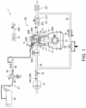
- Fig. 1 is a view illustrating an engine system 1.
- the engine system 1 may be mounted on a vehicle or an automobile, particularly a four-wheeled automobile.
- the engine system 1 includes an engine 100 and a controller which controls the engine 100.
- the controller is an ECU (Engine Control Unit or Electronic Control Unit) 10 which will be described later.
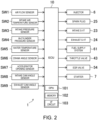
- Fig. 2 is a block diagram illustrating a configuration related to the control of the engine system 1.
- the engine 100 has a cylinder 11. Inside the cylinder 11, intake stroke, compression stroke, expansion stroke, and exhaust stroke are repeated.
- the engine 100 is a four-stroke engine.
- the automobile is propelled by the engine 100 in operation.
- Fuel of the engine 100 is gasoline in this example configuration.
- the engine 100 may be configured so that a mixture gas combusts by self-ignition in at least a part of the operating range. Note that the fuel of the engine 100 may be diesel fuel.
- the engine 100 particularly includes a cylinder block 12 and a cylinder head 13. A plurality of cylinders 11 are formed in the cylinder block 12.
- the engine 100 may be a multicylinder engine. In Fig. 1 , only one cylinder 11 is illustrated.
- a piston 3 is inserted in each cylinder 11.
- the piston 3 is coupled to a crankshaft 15 via a connecting rod 14.
- the piston 3, the cylinder 11, and the cylinder head 13 form a combustion chamber 17.
- the geometric compression ratio of the engine system 1 may be set to a high value for the purpose of improvement in theoretical thermal efficiency.
- the geometric compression ratio ⁇ of the engine system 1 is 14.0:1.0 or higher.
- the geometric compression ratio may be 18:1, for example.
- the geometric compression ratio may be set suitably within a range of 14:1 or higher and 20:1 or lower.
- An intake port 18 is formed in the cylinder head 13 for every cylinder 11.
- the intake port 18 communicates with the inside of the cylinder 11.
- An intake valve 21 is disposed at the intake port 18, and opens and/or closes the intake port 18.
- the intake valve 21 is a poppet valve.
- a valve operating mechanism has an intake cam shaft, and is mechanically connected to the intake valves 21. The valve operating mechanism opens and/or closes the intake valves 21 at a given timing.
- the valve operating mechanism is a variable valve operating mechanism which varies a valve timing and/or a valve lift. As illustrated in Fig. 2 , the valve operating mechanism has an intake S-VT (Sequential-Valve Timing) 23.
- the intake S-VT 23 may continuously change a rotation phase of the intake cam shaft with respect to the crankshaft 15 within a given angle range. A valve opening period of the intake valve 21 may not change.
- the intake S-VT 23 may be a variable phase mechanism.
- the intake S-VT 23 may be of an electric or hydraulic type.
- An exhaust port 19 is formed in the cylinder head 13 for every cylinder 11.
- the exhaust port 19 communicates with the inside of the cylinder 11.
- An exhaust valve 22 is disposed at the exhaust port 19, and opens and/or closes the exhaust port 19.
- the exhaust valve 22 is a poppet valve.
- the valve operating mechanism has an exhaust cam shaft and is mechanically connected to the exhaust valves 22.
- the valve operating mechanism opens and/or closes the exhaust valves 22 at a given timing.
- the valve operating mechanism may be a variable valve operating mechanism which varies a valve timing and/or a valve lift.
- the valve operating mechanism has an exhaust S-VT 24.
- the exhaust S-VT 24 may continuously change a rotation phase of the exhaust cam shaft with respect to the crankshaft 15 within a given angle range. A valve opening period of the exhaust valve 22 may not change.
- the exhaust S-VT 24 may be a variable phase mechanism.
- the exhaust S-VT 24 may be of an electric or hydraulic type.
- An injector 6 is attached to the cylinder head 13 for every cylinder 11.
- the injector 6 may directly inject fuel into the cylinder 11.
- a fuel supply system 61 is connected to the injector 6.
- the fuel supply system 61 includes a fuel tank 63 which stores the fuel, and a fuel supply line 62 which connects the fuel tank 63 to the injector 6.
- a fuel pump 65 and a common rail 64 are particularly provided in the fuel supply line 62.
- the fuel pump 65 pumps the fuel to the common rail 64.
- the common rail 64 stores the fuel pumped from the fuel pump 65, at a high fuel pressure. When a valve of the injector 6 opens, the fuel stored in the common rail 64 is injected into the cylinder 11 from a nozzle hole of the injector 6. Note that the configuration of the fuel supply system 61 is not limited to the configuration described above.
- a spark plug 25 is attached to the cylinder head 13 for every cylinder 11.
- the spark plug 25 forcibly ignites the mixture gas inside the cylinder 11.
- An intake passage 40 is connected to one side surface of the engine 100.
- the intake passage 40 communicates with the intake port 18 of each cylinder 11. Air introduced into the cylinder 11 flows through the intake passage 40.
- An air cleaner 41 which filters the air is disposed at an upstream end part of the intake passage 40.
- a surge tank 42 is disposed near a downstream end of the intake passage 40.
- the intake passage 40 downstream of the surge tank 42 constitutes independent intake passages which are branched for every cylinder 11. Downstream ends of the independent intake passages are connected to the intake ports 18 of the respective cylinders 11.
- a throttle valve 43 may be disposed in the intake passage 40, between the air cleaner 41 and the surge tank 42.
- the throttle valve 43 adjusts an amount of air introduced into the cylinder 11 by being adjusted an opening of its valve.
- An exhaust passage 50 is connected to the other side surface of the engine 100.
- the exhaust passage 50 communicates with the exhaust port 19 of each cylinder 11.
- the exhaust passage 50 is a passage through which exhaust gas discharged from the cylinder 11 flows.
- an upstream part of the exhaust passage 50 constitutes independent exhaust passages which are branched for every cylinder 11. Upstream ends of the independent exhaust passages are connected to the exhaust ports 19 of the respective cylinders 11.
- An exhaust emission control system having one or a plurality of catalytic converters is disposed in the exhaust passage 50.
- the upstream catalytic converter may have a three-way catalyst 511 and a GPF (Gasoline Particulate Filter) 512, for example.
- the downstream catalytic converter may have a three-way catalyst 513.
- the exhaust emission control system is not limited to the illustrated configuration.
- the GPF may be omitted.
- the catalytic converter is not limited to what has the three-way catalyst.
- the disposed order of the three-way catalysts and the GPF may be changed suitably.
- An exhaust gas recirculation (EGR) passage 52 is connected between the intake passage 40 and the exhaust passage 50.
- the EGR passage 52 is a passage for recirculating a part of exhaust gas to the intake passage 40.
- An upstream end of the EGR passage 52 is connected between the upstream catalytic converter and the downstream catalytic converter in the exhaust passage 50.
- a downstream end of the EGR passage 52 is connected between the throttle valve 43 and the surge tank 42 in the intake passage 40.
- a water-cooled EGR cooler 53 may be disposed in the EGR passage 52.
- the EGR cooler 53 cools exhaust gas.
- An EGR valve 54 is also disposed in the EGR passage 52.
- the EGR valve 54 adjusts a flow rate of exhaust gas which flows through the EGR passage 52. By adjusting the opening of the EGR valve 54, a recirculating amount of external EGR gas can be adjusted.
- the engine system 1 is provided with the ECU (Engine Control Unit or Electronic Control Unit) 10 for operating the engine 100.
- the ECU 10 is a controller based on a well-known microcomputer.
- the ECU 10 includes a CPU (Central Processing Unit) 101 which executes a program, memory 102 which is comprised of, for example, RAM (Random Access Memory) and ROM (Read Only Memory) and stores the program and data, and an input and output (I/F) circuit 103 which inputs/outputs an electric signal.
- the ECU 10 is one example of a controller in the present disclosure.
- the ECU 10 is connected to one or various kinds of sensors SW1-SW9.
- the sensors SW1-SW9 output signals to the ECU 10.
- the sensors include at least one of the following sensors:
- the ECU 10 may determine the operating state of the engine 100 based on at least one of the signals from the sensors SW1-SW9, and calculate a controlled variable of each device according to the control logic defined beforehand.
- the control logic is stored in the memory 102, and includes calculating a targeted amount and/or a controlled variable by using a map stored in the memory 102.
- the ECU 10 outputs the electric signals according to the calculated controlled variables to the injector 6, the spark plug 25, the intake S-VT 23, the exhaust S-VT 24, the fuel supply system 61, the throttle valve 43, and the EGR valve 54.
- the engine 100 may also be provided with a starter 7, which is coupled to the crankshaft 15 of the engine 100.
- the starter 7 is an electric motor.
- the ECU 10 When a driver turns on an ignition switch, the ECU 10 outputs an electric signal to the starter 7.
- the starter 7 When the starter 7 is turned on, it rotates the crankshaft 15. Then, motoring of the engine 100 is started. After the motoring is started, the ECU 10 outputs the electric signals to the injector 6 and the spark plug 25 to finish the startup of the engine 100.
- the property of the fuel supplied to the fuel tank 63 is not always the same.
- the property of the fuel supplied to the fuel tank 63 may change greatly compared with a standard fuel.
- the memory 102 of the ECU 10 may store a map which is set based on the property of the standard fuel, and the ECU 10 may control the engine 100 by using the map based on the standard fuel. If the property of the fuel supplied to the engine 100 is changed from the property of the standard fuel, it may cause misfire or rapid combustion.
- this engine system 1 determines the property of the fuel supplied to the engine 100. Further, the engine system 1 corrects the controlled variables of the engine 100 according to the determined property of the fuel.
- the ECU 10 determines the fuel property during the motoring of the engine 100.
- the motoring of the engine 100 is a state where the starter 7 is rotating the crankshaft 15, and the high-temperature oxidation reaction does not occur inside the cylinder 11.
- the ECU 10 can determine the property of fuel, without receiving these influences. Therefore, the determination accuracy is improved.
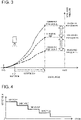
- Fig. 3 illustrates a change of the pressure inside a certain cylinder 11 during the motoring of the engine 100.
- the horizontal axis indicates a progress of the crank angle
- the vertical axis indicates a pressure inside the cylinder 11.
- IVC intake valve 21
- the pressure inside the cylinder 11 starts to increase as the piston 3 moves upward.
- the ECU 10 causes the injector 6 to inject fuel for analysis into the cylinder 11 at a specific timing after IVC.
- the cylinder 11 to which the fuel is injected may be the cylinder 11 whose intake valve 21 is closed first after the crankshaft 15 starts rotation.
- the temperature inside the cylinder 11 increases gradually.
- the heat may affect the determination of the fuel property.
- the ECU 10 can determine the fuel property, without being influenced by the heat. The determination accuracy of the fuel property improves.
- the injector 6 may inject a small amount of fuel with which the high-temperature oxidation reaction does not occur, into the cylinder 11 as the fuel for analysis.
- the fuel injected into the cylinder 11 results in the low-temperature oxidation reaction, through fission, atomization, evaporation, and mixing with air, according to the progress of time, inside the cylinder 11 where the pressure increases gradually with the ascent of the piston 3.
- the amount of heat released also differs. That is, since the initial chemical reaction is different in a preparatory step of the low-temperature oxidation reaction (for example, the in-cylinder gas temperature is 700K), the amount of heat released is different.
- the initial chemical reaction is radical (alkylperoxy RO2, QOOHO2) generation by the hydrogen abstraction reaction.
- the difference in the amount of heat released causes a difference in the rate of pressure increase inside the cylinder 11.
- a broken line in Fig. 3 illustrates the pressure increase when the standard fuel is injected into the cylinder 11.
- the pressure inside the cylinder 11 at a timing where a first period t1 has passed from the fuel injection timing reaches a reference pressure Px.
- the first period t1 is an example of a "specific crank angle period" in the present disclosure.
- the first period t1 corresponds to a period during which the fuel injected into the cylinder 11 from the injector 6 achieves the low-temperature oxidation reaction through fission, atomization, evaporation, and mixing with air.
- the pressure inside the cylinder 11 at a timing where the first period t1 has passed becomes a pressure to which the amount of heat released in the initial chemical reaction of fuel is reflected.
- the first period t1 may be a period before the piston 3 inside the cylinder 11 reaches a compression top dead center (TDC).
- FIG. 3 illustrates the pressure increase when a different type of fuel which is easier to generate heat than the standard fuel is injected into the cylinder 11. Since this type of fuel easily causes the low-temperature oxidation reaction, the pressure increase inside the cylinder 11 is stimulated.
- the pressure inside the cylinder 11 when the first period t1 has passed (a measured pressure PI) is higher than the pressure of the standard fuel.
- FIG 3 illustrates the pressure increase when a different type of fuel which is more difficult to generate heat than the standard fuel is injected into the cylinder 11. Since this type of fuel is difficult to cause the low-temperature oxidation reaction, the pressure increase inside the cylinder 11 is suppressed.
- the pressure inside the cylinder 11 when the first period t1 has passed (a measured pressure P2) is lower than the pressure of the standard fuel.
- the memory 102 stores information on the property of the standard fuel.
- this information is a pressure value (i.e., the reference pressure Px) inside the cylinder 11 when the specific crank angle period (i.e., the first period t1) has passed after the standard fuel is injected into the cylinder 11 at the specific timing.
- the ECU 10 After the injector 6 injects the fuel for analysis, the ECU 10 acquires the pressure value inside the cylinder 11 when the first period t1 has passed, from the measurement signal of the in-cylinder pressure sensor SW4, and compares this measured pressure P with the reference pressure Px stored in the memory 102. If the measured pressure P matches with the reference pressure Px, the ECU 10 can determine that the property of the fuel injected from the injector 6 matches with the property of the standard fuel. When the measured pressure P is higher than the reference pressure Px, the ECU 10 can determine that the fuel injected from the injector 6 is fuel which is easier to generate heat than the standard fuel. When the measured pressure P is lower than the reference pressure Px, the ECU 10 can determine that the fuel injected from the injector 6 is fuel which is more difficult to generate heat than the standard fuel.
- the ECU 10 may determine the fuel property based on the pressure value P measured inside the cylinder 11 whose intake valve 21 is closed first after the crankshaft 15 started rotation. Further, the ECU 10 may measure the pressure value P, not only in the cylinder 11 of which the intake valve 21 is first closed, but also in each of the plurality of cylinders 11 in which a compression stroke takes place thereafter, and may determine the fuel property based on an average value of the plurality of pressure values P. The ECU 10 may measure the pressure values P for 4 to 5 cycles, for example.
- the ECU 10 may change the length of the first period t1 according to progress of the cycle of the engine 100.
- Fig. 4 illustrates a relationship between the progress of the cycle of the engine 100 and the length of the first period t1.
- the length of the first period t1 becomes shorter gradually as the cycle of the engine 100 progresses as the first cycle, the second cycle, the third cycle, and the fourth cycle.
- the ECU 10 After the startup of the engine 100 is finished, the ECU 10 operates the engine 100, while correcting the injection amount of the fuel and/or the close timing of the intake valve 21 (IVC) according to the determined property of the fuel.
- IVC intake valve 21
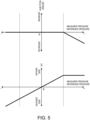
- Fig. 5 illustrates a correction map (upper figure) for the fuel injection amount and a correction map (lower figure) for the valve close timing.
- These correction maps are stored in the memory 102 of the ECU 10.
- the horizontal axis is a value of ⁇ measured pressure ⁇ - ⁇ reference pressure ⁇ , where the left side (i.e., negative) in this drawing indicates that the measured pressure P is lower than the reference pressure Px, and the right side (i.e., positive) in this drawing indicates that the measured pressure P becomes higher than the reference pressure Px.
- the ECU 10 corrects the close timing of the intake valve 21 to the retarding side through the intake S-VT 23.
- the close timing of the intake valve 21 is retarded, since the temperature inside the cylinder 11 drops, the fuel becomes difficult to generate heat. Even if it is the fuel which is easy to generate heat, this combustion becomes equivalent to the combustion with the standard fuel. Note that the close timing of the intake valve 21 is set after an intake bottom dead center.
- the ECU 10 corrects the close timing of the intake valve 21 to the advancing side through the intake S-VT 23.
- the close timing of the intake valve 21 is advanced, since the temperature inside the cylinder 11 increases, the fuel becomes easier to generate heat. Even if it is the fuel which is difficult to generate heat, this combustion becomes equivalent to the combustion with the standard fuel.
- control map of the lower figure of Fig. 5 illustrates the configuration to correct so that the close timing of the intake valve 21 is retarded when the measured pressure P becomes higher than the reference pressure Px, and/or to correct so that the close timing of the intake valve 21 is advanced when the measured pressure P becomes lower than the reference pressure Px.
- the close timing of the intake valve 21 may be retarded as the measured pressure P becomes higher.
- the close timing of the intake valve 21 may be advanced as the measured pressure P becomes lower.
- the temperature inside the cylinder 11 is adjusted to a temperature according to the fuel property.
- the ECU 10 corrects so that fuel injection amount decreases when the measured pressure P becomes higher than the reference pressure Px, as illustrated in the upper figure of Fig. 5 .
- the fuel injection amount may be decreased as the measured pressure P becomes higher. Since the calorific value falls by the reduction in the fuel injection amount, this combustion becomes equivalent to the combustion with the standard fuel.
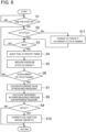
- Step S1 the ECU 10 particularly determines whether it is time for starting the engine 100. If not the time for a startup, the process repeats Step S1, and if it is the time for a startup, the process shifts to Step S2.
- Step S2 the ECU 10 particularly determines whether the number of cycle is the first cycle since the crankshaft 15 started rotation. If it is the first cycle, the process shifts to Step S3, and if it is the second or subsequent cycle, the process shifts to Step S11.
- Step S3 the ECU 10 particularly determines whether the intake valve 21 is closed in the cylinder 11 which is a target for injecting the fuel for analysis. Note that if the number of cycle is the first cycle, it is the intake valve 21 which is first closed after the crankshaft 15 started rotation. If the determination at Step S3 is NO, the process repeats Step S3, and if the determination at Step S3 is YES, the process shifts to Step S4.
- Step S4 the ECU 10 causes the injector 6 to inject the fuel for analysis at a specific timing after the intake valve 21 is closed, at the subsequent Step S5, the ECU 10 acquires the pressure inside the cylinder 11 at a timing the first period t1 has passed from the fuel injection timing, based on the measurement signals from the in-cylinder pressure sensor SW4 and the crank angle sensor SW6.
- Step S6 the ECU 10 particularly determine whether a given number of cycles has passed since the motoring of the engine 100 was started. This given number of cycles is the number of cycles for performing the pressure measurement, and it may be 4 to 5 cycles, for example. If the determination at Step S6 is NO, the process returns to Step S2.
- Step S2 if it is the second or subsequent cycle, the process shifts to Step S11.
- the ECU 10 changed the first period t1 according to the map in Fig. 4 , the ECU 10 performs Steps S3-S5. In this way, the fuel injection into the cylinder 11 and the pressure measurement are repeated a plurality of times.
- Step S6 If the determination at Step S6 becomes YES, the process shifts to Step S7.
- the ECU 10 calculates an average value of the plurality of measured pressure values, and at the subsequent Step S8, it calculates a difference between the measured pressure and the reference pressure according to the standard fuel. Further, at Step S9, the ECU 10 particularly determines whether there is an offset between the measured pressure and the reference pressure, and if there is an offset, the process shifts to Step S10.
- Step S10 according to the control map in Fig. 5 , the ECU 10 corrects the fuel injection amount and/or the close timing of the intake valve 21 particularly after the startup of the engine 100 is finished, based on the fuel property. On the other hand, if there is no offset, the ECU 10 does not correct the fuel injection amount and the close timing of the intake valve 21.
- the ECU 10 can determine the fuel property with sufficient accuracy because the fuel for analysis is injected into the cylinder 11 in the compression stroke, during motoring of the engine 100.
- the combustion under operation of the engine 100 becomes equivalent to the combustion with the standard fuel by correcting the controlled variables of the engine 100 according to the determined property of the fuel, the improvement in fuel efficiency and the improvement in emission gas performance are achieved. In addition, the increase in combustion noise can be suppressed.
- the technique disclosed herein is not limited to being applied to the engine system 1 having the configuration described above.
- the technique disclosed herein is applicable to engine systems 1 of various configurations.
- the technique disclosed herein is also applied to diesel engines.
- the technique disclosed herein is also applicable to so-called “hybrid vehicles.”
- the engine motoring may be performed by a generator.
- an engine may be started in response to a power generation demand or a torque demand.
- the ECU 10 may determine the fuel property, when the engine is started, according to the power generation demand or the torque demand.
Landscapes
- Engineering & Computer Science (AREA)
- Chemical & Material Sciences (AREA)
- Combustion & Propulsion (AREA)
- Mechanical Engineering (AREA)
- General Engineering & Computer Science (AREA)
- Combined Controls Of Internal Combustion Engines (AREA)
- Electrical Control Of Air Or Fuel Supplied To Internal-Combustion Engine (AREA)
Abstract
Description
- The present disclosure relates to a method of controlling an engine and an engine system.
-
JP2014-234727A - Meanwhile, various additives are contained in the fuel supplied to automobile engines, and the type and the combination rate of the additives are different for different manufacturers. Therefore, the properties of the fuel supplied to the automobile engines are not always the same. In some cases, biofuel may be supplied to the engines. The property of the biofuel may be completely different from the property of the fossil fuel. In the future, it is expected that fuel of various properties will be supplied to engines.
- On the other hand, a controller of the engine controls the engine by setting beforehand a fuel injection timing and a fuel injection amount which are used for optimal combustion based on the property of a standard fuel. If the property of fuel supplied to the automobile is different from the standard fuel, it may cause misfire or rapid combustion. Therefore, there is a demand of accurately determining the property of fuel supplied to the engine.
- The technique disclosed herein enables a determination of the property of fuel supplied to an engine with sufficient accuracy.
- According to one aspect of the present disclosure, a method of controlling an engine is provided. The method includes injecting, during motoring of the engine, by an injector, fuel for analysis into a cylinder at a specific timing after an intake valve of the cylinder of the engine is closed. The method includes outputting to a controller, by an in-cylinder pressure sensor, a signal corresponding to a pressure inside the cylinder at least at a timing when a specific crank angle period has passed from the fuel injection timing. The method includes determining, by the controller, a property of the fuel injected by the injector, by comparing a pressure value measured by the in-cylinder pressure sensor with a predetermined reference pressure value inside the cylinder. The reference pressure is measured, particularly in advance, at a timing when the specific crank angle period has passed after a standard fuel is injected into the cylinder at the specific timing. In other words, the controller compares a pressure value measured by the in-cylinder pressure sensor with a predetermined reference pressure value. The property of the fuel may be a pressure value measured by the in-cylinder pressure sensor.
- According to the configuration, the injector injects the fuel for analysis into the cylinder during motoring of the engine. Here, "motoring of the engine" may refer to a state where a crankshaft of the engine starts rotation by a drive source outside of the engine, such as a generator, an electric motor, or a starter motor. The motoring of the engine may correspond to a startup of the engine. The startup of the engine may correspond to, in the case of engine vehicles, when an ignition switch of an automobile being turned on by a person onboard, or, in the case of hybrid vehicles, when an engine is started for, for example, a demand of generating power, and satisfying a demand torque.
- During motoring of the engine, intake stroke, compression stroke, expansion stroke, and exhaust stroke are performed inside the cylinder, by an external driving force. The injector injects the fuel for analysis into the cylinder at the specific timing during compression stroke after the intake valve is closed. The "fuel for analysis" may be a small amount of fuel with which a high-temperature oxidation reaction does not occur even when a piston reaches a compression top dead center. The "fuel for analysis" is fuel to be supplied into the cylinder in order to determine the property of the fuel.
- The pressure inside the cylinder gradually rises accompanied by the progress of compression stroke. The fuel injected into the cylinder results in the low-temperature oxidation reaction, through fission, atomization, evaporation, and mixing with air, according to the progress of time. If the property of fuel (for example, a ratio of specific heat and/or a gas constant of fuel) differs, the amount of heat released also differs. That is, since the initial chemical reaction is different in a preparatory step of the low-temperature oxidation reaction (for example, an in-cylinder gas temperature is 700 K), the amount of heat released is different. The initial chemical reaction is radical (alkylperoxy RO2, QOOHO2) generation by a hydrogen abstraction reaction. The difference in the amount of heat released causes a difference in the rate of pressure increase inside the cylinder.
- The in-cylinder pressure sensor outputs to the controller the signal corresponding to the pressure inside the cylinder at the timing when the specific crank angle period has passed from the fuel injection timing. If the fuel injected from the injector is fuel which easily generates heat, the pressure value is relatively high. On the other hand, if the fuel does not easily generate heat, the pressure value is relatively low.
- The controller may store the reference pressure value of the standard fuel in advance. The "standard fuel" may be, for example, fuel corresponding to K2202 (Motor Gasoline) or K2204 (Diesel Fuel) defined by Japanese Industrial Standards (JIS). The reference pressure value of the standard fuel is the pressure value inside the cylinder at the timing when the specific crank angle period has passed after the standard fuel is injected into the cylinder at the specific timing. Further, the controller compares the pressure value measured by the in-cylinder pressure sensor with the reference pressure value of the standard fuel.
- In detail, if the measured pressure value is higher than the reference pressure value, the fuel injected from the injector easily generates heat, which easily causes the low-temperature oxidation reaction. Therefore, this type of fuel will easily cause the high-temperature oxidation reaction under the engine operation after the startup is finished (that is, when the engine operates by the fuel injected into the cylinder being combusted, unlike the motoring). In this case, the combustion inside the cylinder tends to be rapid and combustion noise tends to increase.
- On the other hand, if the measured pressure value is lower than the reference pressure value of the standard fuel, the fuel injected from the injector does not easily generate heat, which does not easily cause the low-temperature oxidation reaction. Therefore, this type of fuel does not easily cause the high-temperature oxidation reaction under the engine operation after the startup is finished, and as a result, the combustion may be slow. This may lead to a reduction in engine torque and the degradation of fuel efficiency.
- This technique is made by focusing on the idea that the amount of heat released varies depending on fuel. The controller compares the pressure values at the timing when the specific crank angle period has passed after the fuel injection timing, based on the rate of pressure increase inside the cylinder varying according to the heat release amount of the fuel injected into the cylinder. The controller can determine the property of fuel supplied to the engine with sufficient accuracy.
- Notably, the determination of the fuel property is performed during motoring of the engine. Since the high-temperature oxidation reaction of fuel does not occur under these circumstances, the controller can determine the fuel property without being influenced by heat or residual gas. Thus, the controller can determine more accurately the property of fuel supplied to the engine.
- The cylinder may be one of a plurality of cylinders, and the cylinder into which the injector injects the fuel for analysis may be the cylinder, out of the plurality of cylinders, whose the intake valve is closed first after a crankshaft of the engine starts rotation.
- The rotation speed of the crankshaft gradually increases accompanied by the progress of the engine cycle, and accordingly, the in-cylinder temperature gradually increases. When the in-cylinder temperature increases, the determination of the fuel property may be influenced by heat.
- According to this configuration, since the determination of the fuel property is performed inside the cylinder whose intake valve is closed first after the crankshaft of the engine starts rotation, the controller can determine the fuel property without being influenced by heat or residual gas.
- The injector may inject the fuel for analysis to each of the plurality of cylinders as a cycle of the engine progresses. The in-cylinder pressure sensor may output the pressure values of the plurality of cylinders. The controller may compare an average value of the plurality of pressure values with the reference pressure value to determine the property.
- According to this configuration, the determination accuracy improves by the controller using the average value of the plurality of pressure values to determine the fuel property.
- The specific crank angle period may become shorter as the cycle progresses.
- As described above, the in-cylinder temperature gradually increases accompanied by the progress of the engine cycle. The temperature increase inside the cylinder makes the fuel injected into the cylinder more reactive, which promotes the pressure increase inside the cylinder. By the specific crank angle period becoming shorter as the cycle progresses, the pressure value from which the influence of the temperature increase in each of the cycles is eliminated, can be measured. Thus, the controller can further accurately determine the fuel property based on the plurality of pressure values.
- The specific crank angle period may correspond to a period during which the fuel injected into the cylinder from the injector achieves a low-temperature oxidation reaction through fission, atomization, evaporation, and mixing with air.
- As described above, this technique is for determining the fuel property by making use of the fact that the heat release amount in the initial chemical reaction is different. By corresponding the specific crank angle period from the fuel injection timing to the measuring timing of the pressure, to the period during which the fuel reaches the low-temperature oxidation reaction through fission, atomization, evaporation, and mixing with air, the in-cylinder pressure sensor can measure the pressure value to which the heat release amount in the initial chemical reaction is reflected. The controller can determine the fuel property with sufficient accuracy using the pressure value. Note that the specific crank angle period may be set as a period until the piston inside the cylinder reaches a compression top dead center.
- After a startup of the engine is finished, the controller may correct at least one of a fuel injection amount and a close timing of the intake valve according to the property of the fuel.
- When the fuel injected from the injector easily causes the low-temperature oxidation reaction, the high-temperature oxidation reaction occurs more easily, which may cause the rapid combustion. When the fuel injected from the injector does not easily cause the low-temperature oxidation reaction, the high-temperature oxidation reaction occurs less easily, which may cause the slow combustion.
- According to this configuration, since the controller corrects at least one of the fuel injection amount and the close timing of the intake valve according to the property of the fuel, the fuel is regarded to be standardized regardless of the fuel property. That is, it can make the combustion equivalent to the combustion with the standard fuel regardless of the fuel property. It becomes advantageous for the improvement in fuel efficiency of the engine and the improvement in emission gas performance. Further, the increase in combustion noise can be suppressed.
- The controller may correct the close timing of the intake valve to a retarding side when the measured pressure value is higher than the reference pressure value, and/or correct the close timing of the intake valve to an advancing side when the measured pressure value is lower than the reference pressure value.
- When the measured pressure value is higher than the reference pressure value, this fuel is relatively easy to generate heat. Thus, the close timing of the intake valve is corrected to the retarding side. When the close timing of the intake valve is retarded, since the temperature inside the cylinder drops, the fuel becomes difficult to generate heat. Even if it is the fuel which is easy to generate heat, this combustion becomes equivalent to the combustion with the standard fuel. On the contrary, when the measured pressure value is lower than the reference pressure value, this fuel is relatively difficult to generate heat. Thus, the close timing of the intake valve is corrected to the advancing side. When the close timing of the intake valve is advanced, since the temperature inside the cylinder increases, the fuel becomes easier to generate heat. Even if it is the fuel which is difficult to generate heat, this combustion becomes equivalent to the combustion with the standard fuel. Note that the close timing of the intake valve is set after an intake bottom dead center.
- The controller may correct the close timing of the intake valve so that the close timing of the intake valve is retarded more when the measured pressure value becomes higher than the reference pressure value. Particularly, the controller may correct the close timing of the intake valve so that the close timing of the intake valve is retarded more as the measured pressure value becomes higher when the measured pressure value is higher than the reference pressure value. When the valve close timing reaches a maximum retard amount, the controller may correct the fuel injection amount so that the fuel injection amount decreases when the measured pressure value becomes higher than the reference pressure value. Particularly, when the valve close timing reaches a maximum retard amount, the controller may correct the fuel injection amount so that the fuel injection amount decreases as the measured pressure value becomes higher when the measured pressure value is higher than the reference pressure value.
- According to this configuration, by correcting the close timing of the intake valve to be retarded more when the measured pressure value becomes higher than the reference pressure value, the temperature inside the cylinder is adjusted according to the fuel property (i.e., the temperature decreases). However, when the close timing of the intake valve reaches the maximum retard amount, it is hard to decrease the temperature inside the cylinder any further even if the close timing of the intake valve is retarded further. Thus, the controller does not retard the close timing of the intake valve beyond the maximum retard amount, but alternatively, the controller reduces the fuel injection amount. Since the heat release amount decreases accordingly, the combustion becomes equivalent to the combustion with the standard fuel.
- According to another aspect of the present disclosure, an engine system including an engine is provided, which includes a controller that stores information regarding a property of a standard fuel, an injector that injects fuel into a cylinder of the engine, in response to a control signal from the controller, an in-cylinder pressure sensor that is attached to the engine, and outputs to the controller a pressure signal corresponding to a pressure inside the cylinder, and a crank angle sensor that is attached to the engine, and outputs to the controller a crank angle signal corresponding to a crank angle of the engine. During motoring of the engine, the controller causes the injector to inject fuel for analysis at a specific timing after an intake valve of the cylinder is closed. The controller acquires a pressure value inside the cylinder at a timing when a specific crank angle period has passed from the fuel injection timing, based on the crank angle signal of the crank angle sensor and the pressure signal of the in-cylinder pressure sensor. The information stored in the controller includes a reference pressure value inside the cylinder at a timing when the specific crank angle period has passed after the standard fuel is injected into the cylinder at the specific timing. The controller determines the property of the fuel injected by the injector, based on a comparison of the acquired pressure value with the reference pressure value.
- According to this configuration, the controller can determine the property of fuel supplied to the engine, with sufficient accuracy, during motoring of the engine.
-
-
Fig. 1 illustrates an engine system. -
Fig. 2 illustrates the engine system. -
Fig. 3 illustrates a difference in a pressure change inside a cylinder when injecting a plurality of kinds of fuel with different properties. -
Fig. 4 illustrates a relationship between a progress of a cycle and a first period of a pressure value. -
Fig. 5 illustrates a correction map of a fuel injection amount and a valve close timing of an intake valve. -
Fig. 6 illustrates a control flow of the engine system executed by a controller. - Hereinafter, one embodiment of a method of controlling an engine and an engine system is described with reference to the accompanying drawings. All of the features as shown in the drawings may not necessarily be essential. The controlling method and the engine system which are described herein are merely illustration.
-
Fig. 1 is a view illustrating anengine system 1. Theengine system 1 may be mounted on a vehicle or an automobile, particularly a four-wheeled automobile. Theengine system 1 includes anengine 100 and a controller which controls theengine 100. The controller is an ECU (Engine Control Unit or Electronic Control Unit) 10 which will be described later.Fig. 2 is a block diagram illustrating a configuration related to the control of theengine system 1. - The
engine 100 has acylinder 11. Inside thecylinder 11, intake stroke, compression stroke, expansion stroke, and exhaust stroke are repeated. Theengine 100 is a four-stroke engine. The automobile is propelled by theengine 100 in operation. Fuel of theengine 100 is gasoline in this example configuration. Theengine 100 may be configured so that a mixture gas combusts by self-ignition in at least a part of the operating range. Note that the fuel of theengine 100 may be diesel fuel. - The
engine 100 particularly includes acylinder block 12 and acylinder head 13. A plurality ofcylinders 11 are formed in thecylinder block 12. Theengine 100 may be a multicylinder engine. InFig. 1 , only onecylinder 11 is illustrated. - A
piston 3 is inserted in eachcylinder 11. Thepiston 3 is coupled to acrankshaft 15 via a connectingrod 14. Thepiston 3, thecylinder 11, and thecylinder head 13 form acombustion chamber 17. - The geometric compression ratio of the
engine system 1 may be set to a high value for the purpose of improvement in theoretical thermal efficiency. In detail, the geometric compression ratio ε of theengine system 1 is 14.0:1.0 or higher. The geometric compression ratio may be 18:1, for example. The geometric compression ratio may be set suitably within a range of 14:1 or higher and 20:1 or lower. - An
intake port 18 is formed in thecylinder head 13 for everycylinder 11. Theintake port 18 communicates with the inside of thecylinder 11. - An
intake valve 21 is disposed at theintake port 18, and opens and/or closes theintake port 18. Theintake valve 21 is a poppet valve. A valve operating mechanism has an intake cam shaft, and is mechanically connected to theintake valves 21. The valve operating mechanism opens and/or closes theintake valves 21 at a given timing. The valve operating mechanism is a variable valve operating mechanism which varies a valve timing and/or a valve lift. As illustrated inFig. 2 , the valve operating mechanism has an intake S-VT (Sequential-Valve Timing) 23. The intake S-VT 23 may continuously change a rotation phase of the intake cam shaft with respect to thecrankshaft 15 within a given angle range. A valve opening period of theintake valve 21 may not change. The intake S-VT 23 may be a variable phase mechanism. The intake S-VT 23 may be of an electric or hydraulic type. - An
exhaust port 19 is formed in thecylinder head 13 for everycylinder 11. Theexhaust port 19 communicates with the inside of thecylinder 11. - An
exhaust valve 22 is disposed at theexhaust port 19, and opens and/or closes theexhaust port 19. Theexhaust valve 22 is a poppet valve. The valve operating mechanism has an exhaust cam shaft and is mechanically connected to theexhaust valves 22. The valve operating mechanism opens and/or closes theexhaust valves 22 at a given timing. The valve operating mechanism may be a variable valve operating mechanism which varies a valve timing and/or a valve lift. As illustrated inFig. 2 , the valve operating mechanism has an exhaust S-VT 24. The exhaust S-VT 24 may continuously change a rotation phase of the exhaust cam shaft with respect to thecrankshaft 15 within a given angle range. A valve opening period of theexhaust valve 22 may not change. The exhaust S-VT 24 may be a variable phase mechanism. The exhaust S-VT 24 may be of an electric or hydraulic type. - An
injector 6 is attached to thecylinder head 13 for everycylinder 11. Theinjector 6 may directly inject fuel into thecylinder 11. - A
fuel supply system 61 is connected to theinjector 6. Thefuel supply system 61 includes afuel tank 63 which stores the fuel, and afuel supply line 62 which connects thefuel tank 63 to theinjector 6. Afuel pump 65 and acommon rail 64 are particularly provided in thefuel supply line 62. Thefuel pump 65 pumps the fuel to thecommon rail 64. Thecommon rail 64 stores the fuel pumped from thefuel pump 65, at a high fuel pressure. When a valve of theinjector 6 opens, the fuel stored in thecommon rail 64 is injected into thecylinder 11 from a nozzle hole of theinjector 6. Note that the configuration of thefuel supply system 61 is not limited to the configuration described above. - A
spark plug 25 is attached to thecylinder head 13 for everycylinder 11. Thespark plug 25 forcibly ignites the mixture gas inside thecylinder 11. - An
intake passage 40 is connected to one side surface of theengine 100. Theintake passage 40 communicates with theintake port 18 of eachcylinder 11. Air introduced into thecylinder 11 flows through theintake passage 40. Anair cleaner 41 which filters the air is disposed at an upstream end part of theintake passage 40. Asurge tank 42 is disposed near a downstream end of theintake passage 40. Theintake passage 40 downstream of thesurge tank 42 constitutes independent intake passages which are branched for everycylinder 11. Downstream ends of the independent intake passages are connected to theintake ports 18 of therespective cylinders 11. - A
throttle valve 43 may be disposed in theintake passage 40, between theair cleaner 41 and thesurge tank 42. Thethrottle valve 43 adjusts an amount of air introduced into thecylinder 11 by being adjusted an opening of its valve. - An
exhaust passage 50 is connected to the other side surface of theengine 100. Theexhaust passage 50 communicates with theexhaust port 19 of eachcylinder 11. Theexhaust passage 50 is a passage through which exhaust gas discharged from thecylinder 11 flows. Although the detailed illustration is omitted, an upstream part of theexhaust passage 50 constitutes independent exhaust passages which are branched for everycylinder 11. Upstream ends of the independent exhaust passages are connected to theexhaust ports 19 of therespective cylinders 11. - An exhaust emission control system having one or a plurality of catalytic converters is disposed in the
exhaust passage 50. The upstream catalytic converter may have a three-way catalyst 511 and a GPF (Gasoline Particulate Filter) 512, for example. The downstream catalytic converter may have a three-way catalyst 513. Note that the exhaust emission control system is not limited to the illustrated configuration. For example, the GPF may be omitted. Further, the catalytic converter is not limited to what has the three-way catalyst. Moreover, the disposed order of the three-way catalysts and the GPF may be changed suitably. - An exhaust gas recirculation (EGR) passage 52 is connected between the
intake passage 40 and theexhaust passage 50. The EGR passage 52 is a passage for recirculating a part of exhaust gas to theintake passage 40. An upstream end of the EGR passage 52 is connected between the upstream catalytic converter and the downstream catalytic converter in theexhaust passage 50. A downstream end of the EGR passage 52 is connected between thethrottle valve 43 and thesurge tank 42 in theintake passage 40. - A water-cooled
EGR cooler 53 may be disposed in the EGR passage 52. TheEGR cooler 53 cools exhaust gas. AnEGR valve 54 is also disposed in the EGR passage 52. TheEGR valve 54 adjusts a flow rate of exhaust gas which flows through the EGR passage 52. By adjusting the opening of theEGR valve 54, a recirculating amount of external EGR gas can be adjusted. - As illustrated in
Fig. 2 , theengine system 1 is provided with the ECU (Engine Control Unit or Electronic Control Unit) 10 for operating theengine 100. TheECU 10 is a controller based on a well-known microcomputer. TheECU 10 includes a CPU (Central Processing Unit) 101 which executes a program,memory 102 which is comprised of, for example, RAM (Random Access Memory) and ROM (Read Only Memory) and stores the program and data, and an input and output (I/F)circuit 103 which inputs/outputs an electric signal. TheECU 10 is one example of a controller in the present disclosure. - As illustrated in
Figs. 1 and2 , theECU 10 is connected to one or various kinds of sensors SW1-SW9. The sensors SW1-SW9 output signals to theECU 10. The sensors include at least one of the following sensors: - Air flow sensor SW1: Disposed in the
intake passage 40, downstream of theair cleaner 41, and measuring a flow rate of air which flows through theintake passage 40; - Intake air temperature sensor SW2: Disposed in the
intake passage 40, downstream of theair cleaner 41, and measuring the temperature of air which flows through theintake passage 40; - Intake pressure sensor SW3: Attached to the
surge tank 42, and measuring the pressure of air introduced into thecylinder 11; - In-cylinder pressure sensor SW4: Attached to the
cylinder head 13 corresponding to eachcylinder 11, and measuring the pressure inside eachcylinder 11; - Water temperature sensor SW5: Attached to the
engine 100, and measuring the temperature of coolant; - Crank angle sensor SW6: Attached to the
engine 100, and measuring a rotation angle of thecrankshaft 15; - Accelerator opening sensor SW7: Attached to an accelerator pedal mechanism, and measuring an accelerator opening corresponding to an operating amount of the accelerator pedal;
- Intake cam angle sensor SW8: Attached to the
engine 100, and measuring a rotation angle of the intake cam shaft; and - Exhaust cam angle sensor SW9: Attached to the
engine 100, and measuring a rotation angle of the exhaust cam shaft. - The
ECU 10 may determine the operating state of theengine 100 based on at least one of the signals from the sensors SW1-SW9, and calculate a controlled variable of each device according to the control logic defined beforehand. The control logic is stored in thememory 102, and includes calculating a targeted amount and/or a controlled variable by using a map stored in thememory 102. - The
ECU 10 outputs the electric signals according to the calculated controlled variables to theinjector 6, thespark plug 25, the intake S-VT 23, the exhaust S-VT 24, thefuel supply system 61, thethrottle valve 43, and theEGR valve 54. - The
engine 100 may also be provided with astarter 7, which is coupled to thecrankshaft 15 of theengine 100. Thestarter 7 is an electric motor. When a driver turns on an ignition switch, theECU 10 outputs an electric signal to thestarter 7. When thestarter 7 is turned on, it rotates thecrankshaft 15. Then, motoring of theengine 100 is started. After the motoring is started, theECU 10 outputs the electric signals to theinjector 6 and thespark plug 25 to finish the startup of theengine 100. - The property of the fuel supplied to the
fuel tank 63 is not always the same. The property of the fuel supplied to thefuel tank 63 may change greatly compared with a standard fuel. - The
memory 102 of theECU 10 may store a map which is set based on the property of the standard fuel, and theECU 10 may control theengine 100 by using the map based on the standard fuel. If the property of the fuel supplied to theengine 100 is changed from the property of the standard fuel, it may cause misfire or rapid combustion. - Thus, this
engine system 1 determines the property of the fuel supplied to theengine 100. Further, theengine system 1 corrects the controlled variables of theengine 100 according to the determined property of the fuel. - First, a method of determining the fuel property is described with reference to the drawings.
- The
ECU 10 determines the fuel property during the motoring of theengine 100. The motoring of theengine 100 is a state where thestarter 7 is rotating thecrankshaft 15, and the high-temperature oxidation reaction does not occur inside thecylinder 11. During the motoring of theengine 100, since heat is not generated by the reaction of fuel inside thecylinder 11 and residual combustion gas is not produced, theECU 10 can determine the property of fuel, without receiving these influences. Therefore, the determination accuracy is improved. -
Fig. 3 illustrates a change of the pressure inside acertain cylinder 11 during the motoring of theengine 100. InFig. 3 , the horizontal axis indicates a progress of the crank angle, and the vertical axis indicates a pressure inside thecylinder 11. As illustrated by a solid line, after theintake valve 21 is closed (i.e., IVC), the pressure inside thecylinder 11 starts to increase as thepiston 3 moves upward. - The
ECU 10 causes theinjector 6 to inject fuel for analysis into thecylinder 11 at a specific timing after IVC. Thecylinder 11 to which the fuel is injected may be thecylinder 11 whoseintake valve 21 is closed first after thecrankshaft 15 starts rotation. - As the cycle of the
engine 100 progresses as the first cycle, the second cycle, and so on, the temperature inside thecylinder 11 increases gradually. When the temperature inside thecylinder 11 increases, the heat may affect the determination of the fuel property. By using thecylinder 11 whoseintake valve 21 is closed first, theECU 10 can determine the fuel property, without being influenced by the heat. The determination accuracy of the fuel property improves. - Here, the
injector 6 may inject a small amount of fuel with which the high-temperature oxidation reaction does not occur, into thecylinder 11 as the fuel for analysis. - The fuel injected into the
cylinder 11 results in the low-temperature oxidation reaction, through fission, atomization, evaporation, and mixing with air, according to the progress of time, inside thecylinder 11 where the pressure increases gradually with the ascent of thepiston 3. - Here, if the property of fuel (for example, a ratio of specific heat and/or a gas constant of fuel) differs, the amount of heat released also differs. That is, since the initial chemical reaction is different in a preparatory step of the low-temperature oxidation reaction (for example, the in-cylinder gas temperature is 700K), the amount of heat released is different. The initial chemical reaction is radical (alkylperoxy RO2, QOOHO2) generation by the hydrogen abstraction reaction. The difference in the amount of heat released causes a difference in the rate of pressure increase inside the
cylinder 11. A broken line inFig. 3 illustrates the pressure increase when the standard fuel is injected into thecylinder 11. For the standard fuel, the pressure inside thecylinder 11 at a timing where a first period t1 has passed from the fuel injection timing reaches a reference pressure Px. The first period t1 is an example of a "specific crank angle period" in the present disclosure. - The first period t1 corresponds to a period during which the fuel injected into the
cylinder 11 from theinjector 6 achieves the low-temperature oxidation reaction through fission, atomization, evaporation, and mixing with air. The pressure inside thecylinder 11 at a timing where the first period t1 has passed becomes a pressure to which the amount of heat released in the initial chemical reaction of fuel is reflected. Note that the first period t1 may be a period before thepiston 3 inside thecylinder 11 reaches a compression top dead center (TDC). - Contrary to the standard fuel, when a different type of fuel with a different property is injected into the
cylinder 11, the rate of pressure increase inside thecylinder 11 is different because the amount of heat released is different. A dotted line inFig. 3 illustrates the pressure increase when a different type of fuel which is easier to generate heat than the standard fuel is injected into thecylinder 11. Since this type of fuel easily causes the low-temperature oxidation reaction, the pressure increase inside thecylinder 11 is stimulated. The pressure inside thecylinder 11 when the first period t1 has passed (a measured pressure PI) is higher than the pressure of the standard fuel. Further, a one-dot chain line inFig. 3 illustrates the pressure increase when a different type of fuel which is more difficult to generate heat than the standard fuel is injected into thecylinder 11. Since this type of fuel is difficult to cause the low-temperature oxidation reaction, the pressure increase inside thecylinder 11 is suppressed. The pressure inside thecylinder 11 when the first period t1 has passed (a measured pressure P2) is lower than the pressure of the standard fuel. - The
memory 102 stores information on the property of the standard fuel. In more detail, this information is a pressure value (i.e., the reference pressure Px) inside thecylinder 11 when the specific crank angle period (i.e., the first period t1) has passed after the standard fuel is injected into thecylinder 11 at the specific timing. - After the
injector 6 injects the fuel for analysis, theECU 10 acquires the pressure value inside thecylinder 11 when the first period t1 has passed, from the measurement signal of the in-cylinder pressure sensor SW4, and compares this measured pressure P with the reference pressure Px stored in thememory 102. If the measured pressure P matches with the reference pressure Px, theECU 10 can determine that the property of the fuel injected from theinjector 6 matches with the property of the standard fuel. When the measured pressure P is higher than the reference pressure Px, theECU 10 can determine that the fuel injected from theinjector 6 is fuel which is easier to generate heat than the standard fuel. When the measured pressure P is lower than the reference pressure Px, theECU 10 can determine that the fuel injected from theinjector 6 is fuel which is more difficult to generate heat than the standard fuel. - Here, the
ECU 10 may determine the fuel property based on the pressure value P measured inside thecylinder 11 whoseintake valve 21 is closed first after thecrankshaft 15 started rotation. Further, theECU 10 may measure the pressure value P, not only in thecylinder 11 of which theintake valve 21 is first closed, but also in each of the plurality ofcylinders 11 in which a compression stroke takes place thereafter, and may determine the fuel property based on an average value of the plurality of pressure values P. TheECU 10 may measure the pressure values P for 4 to 5 cycles, for example. - When the pressure value P is measured in each of the plurality of
cylinders 11, since the piston speed increases as the cycle of theengine 100 during the motoring progresses, the temperature inside thecylinder 11 also increases. When the temperature inside thecylinder 11 increases, since the reaction speed of the fuel injected into thecylinder 11 changes, the pressure when the first period t1 has passed is influenced by the temperature change inside thecylinder 11. - Thus, the
ECU 10 may change the length of the first period t1 according to progress of the cycle of theengine 100.Fig. 4 illustrates a relationship between the progress of the cycle of theengine 100 and the length of the first period t1. The length of the first period t1 becomes shorter gradually as the cycle of theengine 100 progresses as the first cycle, the second cycle, the third cycle, and the fourth cycle. By doing so, the influence of the temperature inside thecylinder 11 gradually increasing can be eliminated, and therefore, theECU 10 can determine the difference in the pressure increase inside thecylinder 11 only resulting from the fuel property. - After the startup of the
engine 100 is finished, theECU 10 operates theengine 100, while correcting the injection amount of the fuel and/or the close timing of the intake valve 21 (IVC) according to the determined property of the fuel. Thus, even if the property of fuel differs, it can make the combustion equivalent to the combustion with the standard fuel, and therefore, it becomes advantageous for the improvement in fuel efficiency of theengine 100 and the improvement in emission gas performance. Further, the increase in combustion noise can be suppressed. -
Fig. 5 illustrates a correction map (upper figure) for the fuel injection amount and a correction map (lower figure) for the valve close timing. These correction maps are stored in thememory 102 of theECU 10. In each correction map, the horizontal axis is a value of {measured pressure}-{reference pressure}, where the left side (i.e., negative) in this drawing indicates that the measured pressure P is lower than the reference pressure Px, and the right side (i.e., positive) in this drawing indicates that the measured pressure P becomes higher than the reference pressure Px. - When the measured pressure P is higher than the reference pressure Px, this fuel is relatively easy to generate heat. Thus, as illustrated in the lower figure of
Fig. 5 , theECU 10 corrects the close timing of theintake valve 21 to the retarding side through the intake S-VT 23. When the close timing of theintake valve 21 is retarded, since the temperature inside thecylinder 11 drops, the fuel becomes difficult to generate heat. Even if it is the fuel which is easy to generate heat, this combustion becomes equivalent to the combustion with the standard fuel. Note that the close timing of theintake valve 21 is set after an intake bottom dead center. - On the contrary, when the measured pressure P is lower than the reference pressure Px, this fuel is relatively difficult to generate heat. Thus, as illustrated in the lower figure of
Fig. 5 , theECU 10 corrects the close timing of theintake valve 21 to the advancing side through the intake S-VT 23. When the close timing of theintake valve 21 is advanced, since the temperature inside thecylinder 11 increases, the fuel becomes easier to generate heat. Even if it is the fuel which is difficult to generate heat, this combustion becomes equivalent to the combustion with the standard fuel. - In more detail, the control map of the lower figure of
Fig. 5 illustrates the configuration to correct so that the close timing of theintake valve 21 is retarded when the measured pressure P becomes higher than the reference pressure Px, and/or to correct so that the close timing of theintake valve 21 is advanced when the measured pressure P becomes lower than the reference pressure Px. Particularly, the close timing of theintake valve 21 may be retarded as the measured pressure P becomes higher. The close timing of theintake valve 21 may be advanced as the measured pressure P becomes lower. Thus, the temperature inside thecylinder 11 is adjusted to a temperature according to the fuel property. - Here, there is a limit for the retarding amount of the close timing of the
intake valve 21, and therefore, even if the close timing of theintake valve 21 is retarded exceeding the maximum retarding amount, the temperature inside thecylinder 11 is difficult to be further dropped. Thus, when the valve close timing reaches the maximum retard amount in the control map illustrated in the lower figure ofFig. 5 , theECU 10 corrects so that fuel injection amount decreases when the measured pressure P becomes higher than the reference pressure Px, as illustrated in the upper figure ofFig. 5 . Particularly, the fuel injection amount may be decreased as the measured pressure P becomes higher. Since the calorific value falls by the reduction in the fuel injection amount, this combustion becomes equivalent to the combustion with the standard fuel. - Next, a procedure of the control executed by the
ECU 10 is described with reference to a flow ofFig. 6 . First, after the start, at Step S1, theECU 10 particularly determines whether it is time for starting theengine 100. If not the time for a startup, the process repeats Step S1, and if it is the time for a startup, the process shifts to Step S2. - At Step S2, the
ECU 10 particularly determines whether the number of cycle is the first cycle since thecrankshaft 15 started rotation. If it is the first cycle, the process shifts to Step S3, and if it is the second or subsequent cycle, the process shifts to Step S11. - At Step S3, the
ECU 10 particularly determines whether theintake valve 21 is closed in thecylinder 11 which is a target for injecting the fuel for analysis. Note that if the number of cycle is the first cycle, it is theintake valve 21 which is first closed after thecrankshaft 15 started rotation. If the determination at Step S3 is NO, the process repeats Step S3, and if the determination at Step S3 is YES, the process shifts to Step S4. - At Step S4, the
ECU 10 causes theinjector 6 to inject the fuel for analysis at a specific timing after theintake valve 21 is closed, at the subsequent Step S5, theECU 10 acquires the pressure inside thecylinder 11 at a timing the first period t1 has passed from the fuel injection timing, based on the measurement signals from the in-cylinder pressure sensor SW4 and the crank angle sensor SW6. - At Step S6, the
ECU 10 particularly determine whether a given number of cycles has passed since the motoring of theengine 100 was started. This given number of cycles is the number of cycles for performing the pressure measurement, and it may be 4 to 5 cycles, for example. If the determination at Step S6 is NO, the process returns to Step S2. - At Step S2, if it is the second or subsequent cycle, the process shifts to Step S11. After the
ECU 10 changed the first period t1 according to the map inFig. 4 , theECU 10 performs Steps S3-S5. In this way, the fuel injection into thecylinder 11 and the pressure measurement are repeated a plurality of times. - If the determination at Step S6 becomes YES, the process shifts to Step S7. The
ECU 10 calculates an average value of the plurality of measured pressure values, and at the subsequent Step S8, it calculates a difference between the measured pressure and the reference pressure according to the standard fuel. Further, at Step S9, theECU 10 particularly determines whether there is an offset between the measured pressure and the reference pressure, and if there is an offset, the process shifts to Step S10. At Step S10, according to the control map inFig. 5 , theECU 10 corrects the fuel injection amount and/or the close timing of theintake valve 21 particularly after the startup of theengine 100 is finished, based on the fuel property. On the other hand, if there is no offset, theECU 10 does not correct the fuel injection amount and the close timing of theintake valve 21. - According to the method of controlling the
engine 100 and theengine system 1 disclosed herein, theECU 10 can determine the fuel property with sufficient accuracy because the fuel for analysis is injected into thecylinder 11 in the compression stroke, during motoring of theengine 100. - Further, since the combustion under operation of the
engine 100 becomes equivalent to the combustion with the standard fuel by correcting the controlled variables of theengine 100 according to the determined property of the fuel, the improvement in fuel efficiency and the improvement in emission gas performance are achieved. In addition, the increase in combustion noise can be suppressed. - Note that the technique disclosed herein is not limited to being applied to the
engine system 1 having the configuration described above. The technique disclosed herein is applicable toengine systems 1 of various configurations. For example, the technique disclosed herein is also applied to diesel engines. - Further, the technique disclosed herein is also applicable to so-called "hybrid vehicles." In this case, the engine motoring may be performed by a generator. Further, in the hybrid vehicle, an engine may be started in response to a power generation demand or a torque demand. The
ECU 10 may determine the fuel property, when the engine is started, according to the power generation demand or the torque demand. - It should be understood that the embodiments herein are illustrative and not restrictive, since the scope of the invention is defined by the appended claims rather than by the description preceding them.
-
- 1
- Engine System
- 10
- ECU (Controller)
- 100
- Engine
- 11
- Cylinder
- 15
- Crankshaft
- 21
- Intake Valve
- 6
- Injector
- SW4
- In-cylinder Pressure Sensor
- SW6
- Crank Angle Sensor
Claims (15)
- A method of controlling an engine (100), comprising the steps of:during motoring of the engine (100), injecting, by an injector (6), fuel for analysis into a cylinder (11) at a specific timing after an intake valve (21) of the cylinder (11) of the engine (100) is closed;outputting to a controller (10), by an in-cylinder pressure sensor (SW4), a signal corresponding to a pressure inside the cylinder (11) at least at a timing when a specific crank angle period has passed from the fuel injection timing; anddetermining, by the controller (10), a property of the fuel injected by the injector (6), by comparing a pressure value measured by the in-cylinder pressure sensor (SW4) with a predetermined reference pressure value inside the cylinder (11) measured at a timing when the specific crank angle period has passed after a standard fuel is injected into the cylinder (11) at the specific timing.
- The method of claim 1,wherein the cylinder (11) is one of a plurality of cylinders (11), andwherein the cylinder (11) into which the injector (6) injects the fuel for analysis is the cylinder (11), out of the plurality of cylinders (11), whose intake valve (21) is closed first after a crankshaft of the engine (100) starts rotation.
- The method of claim 2,wherein the injector (6) injects the fuel for analysis into each of the plurality of cylinders (11) as a cycle of the engine (100) progresses,wherein the in-cylinder pressure sensor (SW4) outputs the pressure values of the plurality of cylinders (11), andwherein the controller (10) compares an average value of the plurality of pressure values with the reference pressure value to determine the property.
- The method of claim 3, wherein the specific crank angle period becomes shorter as the cycle progresses.
- The method of any one of the preceding claims, wherein the specific crank angle period corresponds to a period during which the fuel injected into the cylinder (11) from the injector (6) achieves a low-temperature oxidation reaction through fission, atomization, evaporation, and mixing with air.
- The method of any one of the preceding claims, wherein the controller (10) corrects at least one of a fuel injection amount and a close timing of the intake valve (21) according to the property of the fuel.
- The method of claim 6, wherein after a startup of the engine (100) is finished, the controller (10) corrects at least one of the fuel injection amount and the close timing of the intake valve (21) according to the property of the fuel.
- The method of claim 6 or 7, wherein the controller (10) corrects the close timing of the intake valve (21) to a retarding side when the measured pressure value is higher than the reference pressure value, and/or corrects the close timing of the intake valve (21) to an advancing side when the measured pressure value is lower than the reference pressure value.
- The method of claim 8,
wherein the controller (10) corrects the close timing of the intake valve (21) so that the close timing of the intake valve (21) is retarded more as the measured pressure value becomes higher when the measured pressure value is higher than the reference pressure value. - The method of claim 8 or 9,
wherein when the valve close timing reaches a maximum retard amount, the controller (10) corrects the fuel injection amount so that the fuel injection amount decreases. - The method of claim 10,
wherein when the valve close timing reaches the maximum retard amount, the controller (10) corrects the fuel injection amount so that the fuel injection amount decreases as the measured pressure value becomes higher when the measured pressure value is higher than the reference pressure value. - The method of any one of the preceding claims,
wherein the controller (10) stores the reference pressure value of the standard fuel in advance. - The method of any one of the preceding claims,
wherein the standard fuel is a fuel defined by an industrial standard. - The method of any one of the preceding claims,
wherein the standard fuel is K2202 or K2204 defined by Japanese Industrial Standards. - An engine system (1) including an engine (100), comprising:a controller (10) configured to store information regarding a property of a standard fuel;an injector (6) configured to inject fuel into a cylinder (11) of the engine (100), in response to a control signal from the controller (10);an in-cylinder pressure sensor (SW4) that is attached to the engine (100), and configured to output to the controller (10) a pressure signal corresponding to a pressure inside the cylinder (11); anda crank angle sensor (SW6) that is attached to the engine (100), and configured to output to the controller (10) a crank angle signal corresponding to a crank angle of the engine (100),wherein during motoring of the engine (100), the controller (10) is configured to cause the injector (6) to inject fuel for analysis at a specific timing after an intake valve (21) of the cylinder (11) is closed,wherein the controller (10) is configured to acquire a pressure value inside the cylinder (11) at a timing when a specific crank angle period has passed from the fuel injection timing, based on the crank angle signal of the crank angle sensor (SW6) and the pressure signal of the in-cylinder pressure sensor (SW4),wherein the information stored in the controller (10) includes a reference pressure value inside the cylinder (11) at a timing when the specific crank angle period has passed after the standard fuel is injected into the cylinder (11) at the specific timing, andwherein the controller (10) is configured to determine the property of the fuel injected by the injector (6), based on a comparison of the acquired pressure value with the reference pressure value.
Applications Claiming Priority (1)
| Application Number | Priority Date | Filing Date | Title |
|---|---|---|---|
| JP2021145488A JP7749990B2 (en) | 2021-09-07 | 2021-09-07 | Engine control method and engine system |
Publications (2)
| Publication Number | Publication Date |
|---|---|
| EP4144976A1 true EP4144976A1 (en) | 2023-03-08 |
| EP4144976B1 EP4144976B1 (en) | 2024-01-31 |
Family
ID=82781319
Family Applications (1)
| Application Number | Title | Priority Date | Filing Date |
|---|---|---|---|
| EP22187392.0A Active EP4144976B1 (en) | 2021-09-07 | 2022-07-28 | Engine controlling method and engine system |
Country Status (3)
| Country | Link |
|---|---|
| US (1) | US11891963B2 (en) |
| EP (1) | EP4144976B1 (en) |
| JP (1) | JP7749990B2 (en) |
Families Citing this family (3)
| Publication number | Priority date | Publication date | Assignee | Title |
|---|---|---|---|---|
| JP7725954B2 (en) * | 2021-09-07 | 2025-08-20 | マツダ株式会社 | Engine control method and engine system |
| JP7735737B2 (en) * | 2021-09-07 | 2025-09-09 | マツダ株式会社 | Engine control method and engine system |
| JP7749990B2 (en) * | 2021-09-07 | 2025-10-07 | マツダ株式会社 | Engine control method and engine system |
Citations (8)
| Publication number | Priority date | Publication date | Assignee | Title |
|---|---|---|---|---|
| US20080162017A1 (en) * | 2006-12-27 | 2008-07-03 | Denso Corporation | Engine control, fuel property detection and determination apparatus, and method for the same |
| DE102007023900A1 (en) * | 2007-05-23 | 2008-11-27 | Robert Bosch Gmbh | Method for determining a fuel composition |
| US20080289405A1 (en) * | 2007-05-23 | 2008-11-27 | Robert Bosch Gmbh | Method to determine the composition of a fuel mixture |
| WO2009040633A2 (en) * | 2007-09-25 | 2009-04-02 | Toyota Jidosha Kabushiki Kaisha | Control apparatus and control method for internal combustion engine |
| JP2009250049A (en) * | 2008-04-02 | 2009-10-29 | Toyota Motor Corp | Device for acquiring value corresponding to alcohol concentration in fuel for internal combustion engine |
| US20090306875A1 (en) * | 2008-06-05 | 2009-12-10 | Robert Bosch Llc | Fuel composition recognition and adaptation system |
| US20100305829A1 (en) * | 2009-05-27 | 2010-12-02 | Gm Global Technology Operations, Inc. | Ethanol content determination systems and methods |
| JP2014234727A (en) | 2013-05-31 | 2014-12-15 | トヨタ自動車株式会社 | Heat release rate waveform preparation device and combustion state diagnostic device for internal combustion engine |
Family Cites Families (19)
| Publication number | Priority date | Publication date | Assignee | Title |
|---|---|---|---|---|
| JPH03164537A (en) * | 1989-11-21 | 1991-07-16 | Mitsubishi Electric Corp | Valve timing controller of internal combustion engine |
| US6826905B2 (en) * | 2002-06-04 | 2004-12-07 | International Engine Intellectual Property Company, Llc | Control strategy for regenerating a particulate filter in an exhaust system of an engine having a variable valve actuation mechanism |
| JP4075858B2 (en) * | 2004-06-01 | 2008-04-16 | トヨタ自動車株式会社 | Method for measuring fuel cetane number of internal combustion engine |
| US8763582B2 (en) * | 2005-05-12 | 2014-07-01 | Ford Global Technologies, Llc | Engine starting for engine having adjustable valve operation and port fuel injection |
| JP2008175065A (en) | 2007-01-16 | 2008-07-31 | Denso Corp | Engine control device and fuel property detection device |
| JP2008196409A (en) | 2007-02-14 | 2008-08-28 | Toyota Motor Corp | Combustion control device for internal combustion engine |
| DE102008001307B4 (en) * | 2008-04-22 | 2020-10-22 | Johann Hauber | Method for determining the ignitability of a fuel |
| EP2778378B1 (en) | 2011-10-26 | 2017-09-27 | Toyota Jidosha Kabushiki Kaisha | Fuel property determination device for internal combustion engine |
| JP6323686B2 (en) * | 2015-07-07 | 2018-05-16 | マツダ株式会社 | Engine control device |
| JP6560591B2 (en) * | 2015-10-22 | 2019-08-14 | ヤンマー株式会社 | engine |
| JP6299819B2 (en) * | 2016-08-08 | 2018-03-28 | マツダ株式会社 | Control unit for direct injection engine |
| JP7035916B2 (en) * | 2018-09-03 | 2022-03-15 | マツダ株式会社 | Failure diagnosis device for in-cylinder pressure sensor |
| WO2020110555A1 (en) * | 2018-11-29 | 2020-06-04 | 日立オートモティブシステムズ株式会社 | Control device for internal conbustion engine |
| US11143137B1 (en) * | 2020-06-03 | 2021-10-12 | Caterpillar Inc. | Engine system, combustion control system, and operating method with close-coupled early pilots and cylinder temperature control |
| JP7537234B2 (en) * | 2020-11-10 | 2024-08-21 | マツダ株式会社 | Engine control method and engine system |
| US11306668B1 (en) * | 2021-01-06 | 2022-04-19 | Ford Global Technologies, Llc | Methods and systems for engine valve timing or lift adjustment |
| JP7735737B2 (en) * | 2021-09-07 | 2025-09-09 | マツダ株式会社 | Engine control method and engine system |
| JP7725954B2 (en) * | 2021-09-07 | 2025-08-20 | マツダ株式会社 | Engine control method and engine system |
| JP7749990B2 (en) * | 2021-09-07 | 2025-10-07 | マツダ株式会社 | Engine control method and engine system |
-
2021
- 2021-09-07 JP JP2021145488A patent/JP7749990B2/en active Active
-
2022
- 2022-07-28 EP EP22187392.0A patent/EP4144976B1/en active Active
- 2022-08-25 US US17/895,876 patent/US11891963B2/en active Active
Patent Citations (8)
| Publication number | Priority date | Publication date | Assignee | Title |
|---|---|---|---|---|
| US20080162017A1 (en) * | 2006-12-27 | 2008-07-03 | Denso Corporation | Engine control, fuel property detection and determination apparatus, and method for the same |
| DE102007023900A1 (en) * | 2007-05-23 | 2008-11-27 | Robert Bosch Gmbh | Method for determining a fuel composition |
| US20080289405A1 (en) * | 2007-05-23 | 2008-11-27 | Robert Bosch Gmbh | Method to determine the composition of a fuel mixture |
| WO2009040633A2 (en) * | 2007-09-25 | 2009-04-02 | Toyota Jidosha Kabushiki Kaisha | Control apparatus and control method for internal combustion engine |
| JP2009250049A (en) * | 2008-04-02 | 2009-10-29 | Toyota Motor Corp | Device for acquiring value corresponding to alcohol concentration in fuel for internal combustion engine |
| US20090306875A1 (en) * | 2008-06-05 | 2009-12-10 | Robert Bosch Llc | Fuel composition recognition and adaptation system |
| US20100305829A1 (en) * | 2009-05-27 | 2010-12-02 | Gm Global Technology Operations, Inc. | Ethanol content determination systems and methods |
| JP2014234727A (en) | 2013-05-31 | 2014-12-15 | トヨタ自動車株式会社 | Heat release rate waveform preparation device and combustion state diagnostic device for internal combustion engine |
Also Published As
| Publication number | Publication date |
|---|---|
| US11891963B2 (en) | 2024-02-06 |
| EP4144976B1 (en) | 2024-01-31 |
| JP7749990B2 (en) | 2025-10-07 |
| US20230077080A1 (en) | 2023-03-09 |
| JP2023038653A (en) | 2023-03-17 |
Similar Documents
| Publication | Publication Date | Title |
|---|---|---|
| EP4144976B1 (en) | Engine controlling method and engine system | |
| US8924136B2 (en) | Device and method for controlling start of compression self-ignition engine | |
| US7788017B2 (en) | Engine control, fuel property detection and determination apparatus, and method for the same | |
| US9212615B2 (en) | Start control device of compression self-ignition engine | |
| JP6070346B2 (en) | Heat generation rate waveform creation device and combustion state diagnostic device for internal combustion engine | |
| CN109072806B (en) | Engine control device | |
| JP4861915B2 (en) | Control device for internal combustion engine | |
| EP4144975B1 (en) | Engine controlling method and engine system | |
| EP4148258B1 (en) | Engine controlling method and engine system | |
| JP4833924B2 (en) | Control device for internal combustion engine | |
| US9556801B2 (en) | Driving force control device and driving force control method | |
| US6935312B2 (en) | Internal combustion engine and ignition control method | |
| JP2000064891A (en) | Fuel injection control device for internal combustion engine | |
| US9890722B2 (en) | Fuel injection control method for internal combustion engine | |
| EP2765291A1 (en) | Method for operating a compression ignition internal combustion engine with direct fuel injection | |
| CN110778412B (en) | Control device for compression ignition engine | |
| CN114941592B (en) | internal combustion engine | |
| JP4615501B2 (en) | Control device for internal combustion engine | |
| JP5983559B2 (en) | Heat generation rate waveform creation device and combustion state diagnostic device for internal combustion engine | |
| JP2001207888A (en) | Self ignition internal combustion engine | |
| JP2014190251A (en) | Heat release rate waveform preparation device and combustion state diagnostic device for internal combustion engine |
Legal Events
| Date | Code | Title | Description |
|---|---|---|---|
| PUAI | Public reference made under article 153(3) epc to a published international application that has entered the european phase |
Free format text: ORIGINAL CODE: 0009012 |
|
| STAA | Information on the status of an ep patent application or granted ep patent |
Free format text: STATUS: THE APPLICATION HAS BEEN PUBLISHED |
|
| AK | Designated contracting states |
Kind code of ref document: A1 Designated state(s): AL AT BE BG CH CY CZ DE DK EE ES FI FR GB GR HR HU IE IS IT LI LT LU LV MC MK MT NL NO PL PT RO RS SE SI SK SM TR |
|
| STAA | Information on the status of an ep patent application or granted ep patent |
Free format text: STATUS: REQUEST FOR EXAMINATION WAS MADE |
|
| 17P | Request for examination filed |
Effective date: 20230601 |
|
| RBV | Designated contracting states (corrected) |
Designated state(s): AL AT BE BG CH CY CZ DE DK EE ES FI FR GB GR HR HU IE IS IT LI LT LU LV MC MK MT NL NO PL PT RO RS SE SI SK SM TR |
|
| GRAP | Despatch of communication of intention to grant a patent |
Free format text: ORIGINAL CODE: EPIDOSNIGR1 |
|
| STAA | Information on the status of an ep patent application or granted ep patent |
Free format text: STATUS: GRANT OF PATENT IS INTENDED |
|
| INTG | Intention to grant announced |
Effective date: 20231013 |
|
| GRAS | Grant fee paid |
Free format text: ORIGINAL CODE: EPIDOSNIGR3 |
|
| GRAA | (expected) grant |
Free format text: ORIGINAL CODE: 0009210 |
|
| STAA | Information on the status of an ep patent application or granted ep patent |
Free format text: STATUS: THE PATENT HAS BEEN GRANTED |
|
| AK | Designated contracting states |
Kind code of ref document: B1 Designated state(s): AL AT BE BG CH CY CZ DE DK EE ES FI FR GB GR HR HU IE IS IT LI LT LU LV MC MK MT NL NO PL PT RO RS SE SI SK SM TR |
|
| REG | Reference to a national code |
Ref country code: GB Ref legal event code: FG4D Ref country code: CH Ref legal event code: EP |
|
| REG | Reference to a national code |
Ref country code: DE Ref legal event code: R096 Ref document number: 602022001780 Country of ref document: DE |
|
| REG | Reference to a national code |
Ref country code: IE Ref legal event code: FG4D |
|
| REG | Reference to a national code |
Ref country code: LT Ref legal event code: MG9D |
|
| REG | Reference to a national code |
Ref country code: NL Ref legal event code: MP Effective date: 20240131 |
|
| PG25 | Lapsed in a contracting state [announced via postgrant information from national office to epo] |
Ref country code: IS Free format text: LAPSE BECAUSE OF FAILURE TO SUBMIT A TRANSLATION OF THE DESCRIPTION OR TO PAY THE FEE WITHIN THE PRESCRIBED TIME-LIMIT Effective date: 20240531 |
|
| PG25 | Lapsed in a contracting state [announced via postgrant information from national office to epo] |
Ref country code: LT Free format text: LAPSE BECAUSE OF FAILURE TO SUBMIT A TRANSLATION OF THE DESCRIPTION OR TO PAY THE FEE WITHIN THE PRESCRIBED TIME-LIMIT Effective date: 20240131 |
|
| PG25 | Lapsed in a contracting state [announced via postgrant information from national office to epo] |
Ref country code: GR Free format text: LAPSE BECAUSE OF FAILURE TO SUBMIT A TRANSLATION OF THE DESCRIPTION OR TO PAY THE FEE WITHIN THE PRESCRIBED TIME-LIMIT Effective date: 20240501 |
|
| REG | Reference to a national code |
Ref country code: AT Ref legal event code: MK05 Ref document number: 1654024 Country of ref document: AT Kind code of ref document: T Effective date: 20240131 |
|
| PG25 | Lapsed in a contracting state [announced via postgrant information from national office to epo] |
Ref country code: RS Free format text: LAPSE BECAUSE OF FAILURE TO SUBMIT A TRANSLATION OF THE DESCRIPTION OR TO PAY THE FEE WITHIN THE PRESCRIBED TIME-LIMIT Effective date: 20240430 Ref country code: HR Free format text: LAPSE BECAUSE OF FAILURE TO SUBMIT A TRANSLATION OF THE DESCRIPTION OR TO PAY THE FEE WITHIN THE PRESCRIBED TIME-LIMIT Effective date: 20240131 Ref country code: NL Free format text: LAPSE BECAUSE OF FAILURE TO SUBMIT A TRANSLATION OF THE DESCRIPTION OR TO PAY THE FEE WITHIN THE PRESCRIBED TIME-LIMIT Effective date: 20240131 |
|
| PG25 | Lapsed in a contracting state [announced via postgrant information from national office to epo] |
Ref country code: ES Free format text: LAPSE BECAUSE OF FAILURE TO SUBMIT A TRANSLATION OF THE DESCRIPTION OR TO PAY THE FEE WITHIN THE PRESCRIBED TIME-LIMIT Effective date: 20240131 |
|
| PG25 | Lapsed in a contracting state [announced via postgrant information from national office to epo] |
Ref country code: AT Free format text: LAPSE BECAUSE OF FAILURE TO SUBMIT A TRANSLATION OF THE DESCRIPTION OR TO PAY THE FEE WITHIN THE PRESCRIBED TIME-LIMIT Effective date: 20240131 |
|
| PG25 | Lapsed in a contracting state [announced via postgrant information from national office to epo] |
Ref country code: RS Free format text: LAPSE BECAUSE OF FAILURE TO SUBMIT A TRANSLATION OF THE DESCRIPTION OR TO PAY THE FEE WITHIN THE PRESCRIBED TIME-LIMIT Effective date: 20240430 Ref country code: NO Free format text: LAPSE BECAUSE OF FAILURE TO SUBMIT A TRANSLATION OF THE DESCRIPTION OR TO PAY THE FEE WITHIN THE PRESCRIBED TIME-LIMIT Effective date: 20240430 Ref country code: NL Free format text: LAPSE BECAUSE OF FAILURE TO SUBMIT A TRANSLATION OF THE DESCRIPTION OR TO PAY THE FEE WITHIN THE PRESCRIBED TIME-LIMIT Effective date: 20240131 Ref country code: LT Free format text: LAPSE BECAUSE OF FAILURE TO SUBMIT A TRANSLATION OF THE DESCRIPTION OR TO PAY THE FEE WITHIN THE PRESCRIBED TIME-LIMIT Effective date: 20240131 Ref country code: IS Free format text: LAPSE BECAUSE OF FAILURE TO SUBMIT A TRANSLATION OF THE DESCRIPTION OR TO PAY THE FEE WITHIN THE PRESCRIBED TIME-LIMIT Effective date: 20240531 Ref country code: HR Free format text: LAPSE BECAUSE OF FAILURE TO SUBMIT A TRANSLATION OF THE DESCRIPTION OR TO PAY THE FEE WITHIN THE PRESCRIBED TIME-LIMIT Effective date: 20240131 Ref country code: GR Free format text: LAPSE BECAUSE OF FAILURE TO SUBMIT A TRANSLATION OF THE DESCRIPTION OR TO PAY THE FEE WITHIN THE PRESCRIBED TIME-LIMIT Effective date: 20240501 Ref country code: FI Free format text: LAPSE BECAUSE OF FAILURE TO SUBMIT A TRANSLATION OF THE DESCRIPTION OR TO PAY THE FEE WITHIN THE PRESCRIBED TIME-LIMIT Effective date: 20240131 Ref country code: ES Free format text: LAPSE BECAUSE OF FAILURE TO SUBMIT A TRANSLATION OF THE DESCRIPTION OR TO PAY THE FEE WITHIN THE PRESCRIBED TIME-LIMIT Effective date: 20240131 Ref country code: BG Free format text: LAPSE BECAUSE OF FAILURE TO SUBMIT A TRANSLATION OF THE DESCRIPTION OR TO PAY THE FEE WITHIN THE PRESCRIBED TIME-LIMIT Effective date: 20240131 Ref country code: AT Free format text: LAPSE BECAUSE OF FAILURE TO SUBMIT A TRANSLATION OF THE DESCRIPTION OR TO PAY THE FEE WITHIN THE PRESCRIBED TIME-LIMIT Effective date: 20240131 |
|
| PG25 | Lapsed in a contracting state [announced via postgrant information from national office to epo] |
Ref country code: PT Free format text: LAPSE BECAUSE OF FAILURE TO SUBMIT A TRANSLATION OF THE DESCRIPTION OR TO PAY THE FEE WITHIN THE PRESCRIBED TIME-LIMIT Effective date: 20240531 Ref country code: PL Free format text: LAPSE BECAUSE OF FAILURE TO SUBMIT A TRANSLATION OF THE DESCRIPTION OR TO PAY THE FEE WITHIN THE PRESCRIBED TIME-LIMIT Effective date: 20240131 |
|
| PG25 | Lapsed in a contracting state [announced via postgrant information from national office to epo] |
Ref country code: SE Free format text: LAPSE BECAUSE OF FAILURE TO SUBMIT A TRANSLATION OF THE DESCRIPTION OR TO PAY THE FEE WITHIN THE PRESCRIBED TIME-LIMIT Effective date: 20240131 Ref country code: PT Free format text: LAPSE BECAUSE OF FAILURE TO SUBMIT A TRANSLATION OF THE DESCRIPTION OR TO PAY THE FEE WITHIN THE PRESCRIBED TIME-LIMIT Effective date: 20240531 Ref country code: PL Free format text: LAPSE BECAUSE OF FAILURE TO SUBMIT A TRANSLATION OF THE DESCRIPTION OR TO PAY THE FEE WITHIN THE PRESCRIBED TIME-LIMIT Effective date: 20240131 Ref country code: LV Free format text: LAPSE BECAUSE OF FAILURE TO SUBMIT A TRANSLATION OF THE DESCRIPTION OR TO PAY THE FEE WITHIN THE PRESCRIBED TIME-LIMIT Effective date: 20240131 |
|
| PG25 | Lapsed in a contracting state [announced via postgrant information from national office to epo] |
Ref country code: DK Free format text: LAPSE BECAUSE OF FAILURE TO SUBMIT A TRANSLATION OF THE DESCRIPTION OR TO PAY THE FEE WITHIN THE PRESCRIBED TIME-LIMIT Effective date: 20240131 |
|
| PG25 | Lapsed in a contracting state [announced via postgrant information from national office to epo] |
Ref country code: SM Free format text: LAPSE BECAUSE OF FAILURE TO SUBMIT A TRANSLATION OF THE DESCRIPTION OR TO PAY THE FEE WITHIN THE PRESCRIBED TIME-LIMIT Effective date: 20240131 |
|
| PG25 | Lapsed in a contracting state [announced via postgrant information from national office to epo] |
Ref country code: EE Free format text: LAPSE BECAUSE OF FAILURE TO SUBMIT A TRANSLATION OF THE DESCRIPTION OR TO PAY THE FEE WITHIN THE PRESCRIBED TIME-LIMIT Effective date: 20240131 Ref country code: CZ Free format text: LAPSE BECAUSE OF FAILURE TO SUBMIT A TRANSLATION OF THE DESCRIPTION OR TO PAY THE FEE WITHIN THE PRESCRIBED TIME-LIMIT Effective date: 20240131 |
|
| PG25 | Lapsed in a contracting state [announced via postgrant information from national office to epo] |
Ref country code: SK Free format text: LAPSE BECAUSE OF FAILURE TO SUBMIT A TRANSLATION OF THE DESCRIPTION OR TO PAY THE FEE WITHIN THE PRESCRIBED TIME-LIMIT Effective date: 20240131 |
|
| PG25 | Lapsed in a contracting state [announced via postgrant information from national office to epo] |
Ref country code: SM Free format text: LAPSE BECAUSE OF FAILURE TO SUBMIT A TRANSLATION OF THE DESCRIPTION OR TO PAY THE FEE WITHIN THE PRESCRIBED TIME-LIMIT Effective date: 20240131 Ref country code: SK Free format text: LAPSE BECAUSE OF FAILURE TO SUBMIT A TRANSLATION OF THE DESCRIPTION OR TO PAY THE FEE WITHIN THE PRESCRIBED TIME-LIMIT Effective date: 20240131 Ref country code: RO Free format text: LAPSE BECAUSE OF FAILURE TO SUBMIT A TRANSLATION OF THE DESCRIPTION OR TO PAY THE FEE WITHIN THE PRESCRIBED TIME-LIMIT Effective date: 20240131 Ref country code: EE Free format text: LAPSE BECAUSE OF FAILURE TO SUBMIT A TRANSLATION OF THE DESCRIPTION OR TO PAY THE FEE WITHIN THE PRESCRIBED TIME-LIMIT Effective date: 20240131 Ref country code: DK Free format text: LAPSE BECAUSE OF FAILURE TO SUBMIT A TRANSLATION OF THE DESCRIPTION OR TO PAY THE FEE WITHIN THE PRESCRIBED TIME-LIMIT Effective date: 20240131 Ref country code: CZ Free format text: LAPSE BECAUSE OF FAILURE TO SUBMIT A TRANSLATION OF THE DESCRIPTION OR TO PAY THE FEE WITHIN THE PRESCRIBED TIME-LIMIT Effective date: 20240131 |
|
| REG | Reference to a national code |
Ref country code: DE Ref legal event code: R097 Ref document number: 602022001780 Country of ref document: DE |
|
| PG25 | Lapsed in a contracting state [announced via postgrant information from national office to epo] |
Ref country code: IT Free format text: LAPSE BECAUSE OF FAILURE TO SUBMIT A TRANSLATION OF THE DESCRIPTION OR TO PAY THE FEE WITHIN THE PRESCRIBED TIME-LIMIT Effective date: 20240131 |
|
| PLBE | No opposition filed within time limit |
Free format text: ORIGINAL CODE: 0009261 |
|
| STAA | Information on the status of an ep patent application or granted ep patent |
Free format text: STATUS: NO OPPOSITION FILED WITHIN TIME LIMIT |
|
| PG25 | Lapsed in a contracting state [announced via postgrant information from national office to epo] |
Ref country code: IT Free format text: LAPSE BECAUSE OF FAILURE TO SUBMIT A TRANSLATION OF THE DESCRIPTION OR TO PAY THE FEE WITHIN THE PRESCRIBED TIME-LIMIT Effective date: 20240131 |
|
| 26N | No opposition filed |
Effective date: 20241101 |
|
| PG25 | Lapsed in a contracting state [announced via postgrant information from national office to epo] |
Ref country code: MC Free format text: LAPSE BECAUSE OF FAILURE TO SUBMIT A TRANSLATION OF THE DESCRIPTION OR TO PAY THE FEE WITHIN THE PRESCRIBED TIME-LIMIT Effective date: 20240131 |
|
| PG25 | Lapsed in a contracting state [announced via postgrant information from national office to epo] |
Ref country code: LU Free format text: LAPSE BECAUSE OF NON-PAYMENT OF DUE FEES Effective date: 20240728 |
|
| PG25 | Lapsed in a contracting state [announced via postgrant information from national office to epo] |
Ref country code: LU Free format text: LAPSE BECAUSE OF NON-PAYMENT OF DUE FEES Effective date: 20240728 |
|
| PG25 | Lapsed in a contracting state [announced via postgrant information from national office to epo] |
Ref country code: SI Free format text: LAPSE BECAUSE OF FAILURE TO SUBMIT A TRANSLATION OF THE DESCRIPTION OR TO PAY THE FEE WITHIN THE PRESCRIBED TIME-LIMIT Effective date: 20240131 Ref country code: BE Free format text: LAPSE BECAUSE OF NON-PAYMENT OF DUE FEES Effective date: 20240731 |
|
| PG25 | Lapsed in a contracting state [announced via postgrant information from national office to epo] |
Ref country code: FR Free format text: LAPSE BECAUSE OF NON-PAYMENT OF DUE FEES Effective date: 20240731 |
|
| REG | Reference to a national code |
Ref country code: BE Ref legal event code: MM Effective date: 20240731 |
|
| PG25 | Lapsed in a contracting state [announced via postgrant information from national office to epo] |
Ref country code: IE Free format text: LAPSE BECAUSE OF NON-PAYMENT OF DUE FEES Effective date: 20240728 |
|
| PGFP | Annual fee paid to national office [announced via postgrant information from national office to epo] |
Ref country code: DE Payment date: 20250604 Year of fee payment: 4 |
|
| PG25 | Lapsed in a contracting state [announced via postgrant information from national office to epo] |
Ref country code: CY Free format text: LAPSE BECAUSE OF FAILURE TO SUBMIT A TRANSLATION OF THE DESCRIPTION OR TO PAY THE FEE WITHIN THE PRESCRIBED TIME-LIMIT; INVALID AB INITIO Effective date: 20220728 |
|
| REG | Reference to a national code |
Ref country code: CH Ref legal event code: H13 Free format text: ST27 STATUS EVENT CODE: U-0-0-H10-H13 (AS PROVIDED BY THE NATIONAL OFFICE) Effective date: 20260224 |
|
| PG25 | Lapsed in a contracting state [announced via postgrant information from national office to epo] |
Ref country code: HU Free format text: LAPSE BECAUSE OF FAILURE TO SUBMIT A TRANSLATION OF THE DESCRIPTION OR TO PAY THE FEE WITHIN THE PRESCRIBED TIME-LIMIT; INVALID AB INITIO Effective date: 20220728 |
|
| PG25 | Lapsed in a contracting state [announced via postgrant information from national office to epo] |
Ref country code: CH Free format text: LAPSE BECAUSE OF NON-PAYMENT OF DUE FEES Effective date: 20250731 |