EP4144963A1 - A filter arrangement for a selective catalytic reduction system - Google Patents
A filter arrangement for a selective catalytic reduction system Download PDFInfo
- Publication number
- EP4144963A1 EP4144963A1 EP22186874.8A EP22186874A EP4144963A1 EP 4144963 A1 EP4144963 A1 EP 4144963A1 EP 22186874 A EP22186874 A EP 22186874A EP 4144963 A1 EP4144963 A1 EP 4144963A1
- Authority
- EP
- European Patent Office
- Prior art keywords
- filter
- restraining body
- suction tube
- arrangement
- restraining
- Prior art date
- Legal status (The legal status is an assumption and is not a legal conclusion. Google has not performed a legal analysis and makes no representation as to the accuracy of the status listed.)
- Granted
Links
Images



Classifications
-
- B—PERFORMING OPERATIONS; TRANSPORTING
- B01—PHYSICAL OR CHEMICAL PROCESSES OR APPARATUS IN GENERAL
- B01D—SEPARATION
- B01D35/00—Filtering devices having features not specifically covered by groups B01D24/00 - B01D33/00, or for applications not specifically covered by groups B01D24/00 - B01D33/00; Auxiliary devices for filtration; Filter housing constructions
- B01D35/02—Filters adapted for location in special places, e.g. pipe-lines, pumps, stop-cocks
- B01D35/027—Filters adapted for location in special places, e.g. pipe-lines, pumps, stop-cocks rigidly mounted in or on tanks or reservoirs
-
- F—MECHANICAL ENGINEERING; LIGHTING; HEATING; WEAPONS; BLASTING
- F01—MACHINES OR ENGINES IN GENERAL; ENGINE PLANTS IN GENERAL; STEAM ENGINES
- F01N—GAS-FLOW SILENCERS OR EXHAUST APPARATUS FOR MACHINES OR ENGINES IN GENERAL; GAS-FLOW SILENCERS OR EXHAUST APPARATUS FOR INTERNAL-COMBUSTION ENGINES
- F01N3/00—Exhaust or silencing apparatus having means for purifying, rendering innocuous, or otherwise treating exhaust
- F01N3/08—Exhaust or silencing apparatus having means for purifying, rendering innocuous, or otherwise treating exhaust for rendering innocuous
- F01N3/10—Exhaust or silencing apparatus having means for purifying, rendering innocuous, or otherwise treating exhaust for rendering innocuous by thermal or catalytic conversion of noxious components of exhaust
- F01N3/18—Exhaust or silencing apparatus having means for purifying, rendering innocuous, or otherwise treating exhaust for rendering innocuous by thermal or catalytic conversion of noxious components of exhaust characterised by methods of operation; Control
- F01N3/20—Exhaust or silencing apparatus having means for purifying, rendering innocuous, or otherwise treating exhaust for rendering innocuous by thermal or catalytic conversion of noxious components of exhaust characterised by methods of operation; Control specially adapted for catalytic conversion
- F01N3/206—Adding periodically or continuously substances to exhaust gases for promoting purification, e.g. catalytic material in liquid form, NOx reducing agents
- F01N3/2066—Selective catalytic reduction [SCR]
-
- B—PERFORMING OPERATIONS; TRANSPORTING
- B01—PHYSICAL OR CHEMICAL PROCESSES OR APPARATUS IN GENERAL
- B01D—SEPARATION
- B01D35/00—Filtering devices having features not specifically covered by groups B01D24/00 - B01D33/00, or for applications not specifically covered by groups B01D24/00 - B01D33/00; Auxiliary devices for filtration; Filter housing constructions
- B01D35/26—Filters with built-in pumps filters provided with a pump mounted in or on the casing
-
- B—PERFORMING OPERATIONS; TRANSPORTING
- B01—PHYSICAL OR CHEMICAL PROCESSES OR APPARATUS IN GENERAL
- B01D—SEPARATION
- B01D35/00—Filtering devices having features not specifically covered by groups B01D24/00 - B01D33/00, or for applications not specifically covered by groups B01D24/00 - B01D33/00; Auxiliary devices for filtration; Filter housing constructions
- B01D35/30—Filter housing constructions
- B01D35/306—Filter mounting adapter
-
- B—PERFORMING OPERATIONS; TRANSPORTING
- B01—PHYSICAL OR CHEMICAL PROCESSES OR APPARATUS IN GENERAL
- B01D—SEPARATION
- B01D53/00—Separation of gases or vapours; Recovering vapours of volatile solvents from gases; Chemical or biological purification of waste gases, e.g. engine exhaust gases, smoke, fumes, flue gases, aerosols
- B01D53/34—Chemical or biological purification of waste gases
- B01D53/92—Chemical or biological purification of waste gases of engine exhaust gases
- B01D53/94—Chemical or biological purification of waste gases of engine exhaust gases by catalytic processes
- B01D53/9404—Removing only nitrogen compounds
- B01D53/9409—Nitrogen oxides
- B01D53/9413—Processes characterised by a specific catalyst
- B01D53/9418—Processes characterised by a specific catalyst for removing nitrogen oxides by selective catalytic reduction [SCR] using a reducing agent in a lean exhaust gas
-
- F—MECHANICAL ENGINEERING; LIGHTING; HEATING; WEAPONS; BLASTING
- F01—MACHINES OR ENGINES IN GENERAL; ENGINE PLANTS IN GENERAL; STEAM ENGINES
- F01N—GAS-FLOW SILENCERS OR EXHAUST APPARATUS FOR MACHINES OR ENGINES IN GENERAL; GAS-FLOW SILENCERS OR EXHAUST APPARATUS FOR INTERNAL-COMBUSTION ENGINES
- F01N2610/00—Adding substances to exhaust gases
- F01N2610/02—Adding substances to exhaust gases the substance being ammonia or urea
-
- F—MECHANICAL ENGINEERING; LIGHTING; HEATING; WEAPONS; BLASTING
- F01—MACHINES OR ENGINES IN GENERAL; ENGINE PLANTS IN GENERAL; STEAM ENGINES
- F01N—GAS-FLOW SILENCERS OR EXHAUST APPARATUS FOR MACHINES OR ENGINES IN GENERAL; GAS-FLOW SILENCERS OR EXHAUST APPARATUS FOR INTERNAL-COMBUSTION ENGINES
- F01N2610/00—Adding substances to exhaust gases
- F01N2610/14—Arrangements for the supply of substances, e.g. conduits
-
- F—MECHANICAL ENGINEERING; LIGHTING; HEATING; WEAPONS; BLASTING
- F01—MACHINES OR ENGINES IN GENERAL; ENGINE PLANTS IN GENERAL; STEAM ENGINES
- F01N—GAS-FLOW SILENCERS OR EXHAUST APPARATUS FOR MACHINES OR ENGINES IN GENERAL; GAS-FLOW SILENCERS OR EXHAUST APPARATUS FOR INTERNAL-COMBUSTION ENGINES
- F01N2610/00—Adding substances to exhaust gases
- F01N2610/14—Arrangements for the supply of substances, e.g. conduits
- F01N2610/1406—Storage means for substances, e.g. tanks or reservoirs
-
- F—MECHANICAL ENGINEERING; LIGHTING; HEATING; WEAPONS; BLASTING
- F01—MACHINES OR ENGINES IN GENERAL; ENGINE PLANTS IN GENERAL; STEAM ENGINES
- F01N—GAS-FLOW SILENCERS OR EXHAUST APPARATUS FOR MACHINES OR ENGINES IN GENERAL; GAS-FLOW SILENCERS OR EXHAUST APPARATUS FOR INTERNAL-COMBUSTION ENGINES
- F01N2610/00—Adding substances to exhaust gases
- F01N2610/14—Arrangements for the supply of substances, e.g. conduits
- F01N2610/1406—Storage means for substances, e.g. tanks or reservoirs
- F01N2610/142—Controlling the filling of the tank
-
- F—MECHANICAL ENGINEERING; LIGHTING; HEATING; WEAPONS; BLASTING
- F01—MACHINES OR ENGINES IN GENERAL; ENGINE PLANTS IN GENERAL; STEAM ENGINES
- F01N—GAS-FLOW SILENCERS OR EXHAUST APPARATUS FOR MACHINES OR ENGINES IN GENERAL; GAS-FLOW SILENCERS OR EXHAUST APPARATUS FOR INTERNAL-COMBUSTION ENGINES
- F01N2610/00—Adding substances to exhaust gases
- F01N2610/14—Arrangements for the supply of substances, e.g. conduits
- F01N2610/1426—Filtration means
-
- F—MECHANICAL ENGINEERING; LIGHTING; HEATING; WEAPONS; BLASTING
- F01—MACHINES OR ENGINES IN GENERAL; ENGINE PLANTS IN GENERAL; STEAM ENGINES
- F01N—GAS-FLOW SILENCERS OR EXHAUST APPARATUS FOR MACHINES OR ENGINES IN GENERAL; GAS-FLOW SILENCERS OR EXHAUST APPARATUS FOR INTERNAL-COMBUSTION ENGINES
- F01N2610/00—Adding substances to exhaust gases
- F01N2610/14—Arrangements for the supply of substances, e.g. conduits
- F01N2610/1466—Means for venting air out of conduits or tanks
-
- F—MECHANICAL ENGINEERING; LIGHTING; HEATING; WEAPONS; BLASTING
- F01—MACHINES OR ENGINES IN GENERAL; ENGINE PLANTS IN GENERAL; STEAM ENGINES
- F01N—GAS-FLOW SILENCERS OR EXHAUST APPARATUS FOR MACHINES OR ENGINES IN GENERAL; GAS-FLOW SILENCERS OR EXHAUST APPARATUS FOR INTERNAL-COMBUSTION ENGINES
- F01N2900/00—Details of electrical control or of the monitoring of the exhaust gas treating apparatus
- F01N2900/04—Methods of control or diagnosing
-
- F—MECHANICAL ENGINEERING; LIGHTING; HEATING; WEAPONS; BLASTING
- F01—MACHINES OR ENGINES IN GENERAL; ENGINE PLANTS IN GENERAL; STEAM ENGINES
- F01N—GAS-FLOW SILENCERS OR EXHAUST APPARATUS FOR MACHINES OR ENGINES IN GENERAL; GAS-FLOW SILENCERS OR EXHAUST APPARATUS FOR INTERNAL-COMBUSTION ENGINES
- F01N2900/00—Details of electrical control or of the monitoring of the exhaust gas treating apparatus
- F01N2900/06—Parameters used for exhaust control or diagnosing
- F01N2900/14—Parameters used for exhaust control or diagnosing said parameters being related to the exhaust gas
- F01N2900/1411—Exhaust gas flow rate, e.g. mass flow rate or volumetric flow rate
-
- F—MECHANICAL ENGINEERING; LIGHTING; HEATING; WEAPONS; BLASTING
- F01—MACHINES OR ENGINES IN GENERAL; ENGINE PLANTS IN GENERAL; STEAM ENGINES
- F01N—GAS-FLOW SILENCERS OR EXHAUST APPARATUS FOR MACHINES OR ENGINES IN GENERAL; GAS-FLOW SILENCERS OR EXHAUST APPARATUS FOR INTERNAL-COMBUSTION ENGINES
- F01N2900/00—Details of electrical control or of the monitoring of the exhaust gas treating apparatus
- F01N2900/06—Parameters used for exhaust control or diagnosing
- F01N2900/18—Parameters used for exhaust control or diagnosing said parameters being related to the system for adding a substance into the exhaust
- F01N2900/1806—Properties of reducing agent or dosing system
-
- F—MECHANICAL ENGINEERING; LIGHTING; HEATING; WEAPONS; BLASTING
- F01—MACHINES OR ENGINES IN GENERAL; ENGINE PLANTS IN GENERAL; STEAM ENGINES
- F01N—GAS-FLOW SILENCERS OR EXHAUST APPARATUS FOR MACHINES OR ENGINES IN GENERAL; GAS-FLOW SILENCERS OR EXHAUST APPARATUS FOR INTERNAL-COMBUSTION ENGINES
- F01N2900/00—Details of electrical control or of the monitoring of the exhaust gas treating apparatus
- F01N2900/06—Parameters used for exhaust control or diagnosing
- F01N2900/18—Parameters used for exhaust control or diagnosing said parameters being related to the system for adding a substance into the exhaust
- F01N2900/1806—Properties of reducing agent or dosing system
- F01N2900/1814—Tank level
-
- F—MECHANICAL ENGINEERING; LIGHTING; HEATING; WEAPONS; BLASTING
- F01—MACHINES OR ENGINES IN GENERAL; ENGINE PLANTS IN GENERAL; STEAM ENGINES
- F01N—GAS-FLOW SILENCERS OR EXHAUST APPARATUS FOR MACHINES OR ENGINES IN GENERAL; GAS-FLOW SILENCERS OR EXHAUST APPARATUS FOR INTERNAL-COMBUSTION ENGINES
- F01N3/00—Exhaust or silencing apparatus having means for purifying, rendering innocuous, or otherwise treating exhaust
- F01N3/02—Exhaust or silencing apparatus having means for purifying, rendering innocuous, or otherwise treating exhaust for cooling, or for removing solid constituents of, exhaust
- F01N3/021—Exhaust or silencing apparatus having means for purifying, rendering innocuous, or otherwise treating exhaust for cooling, or for removing solid constituents of, exhaust by means of filters
- F01N3/023—Exhaust or silencing apparatus having means for purifying, rendering innocuous, or otherwise treating exhaust for cooling, or for removing solid constituents of, exhaust by means of filters using means for regenerating the filters, e.g. by burning trapped particles
- F01N3/029—Exhaust or silencing apparatus having means for purifying, rendering innocuous, or otherwise treating exhaust for cooling, or for removing solid constituents of, exhaust by means of filters using means for regenerating the filters, e.g. by burning trapped particles by adding non-fuel substances to exhaust
-
- F—MECHANICAL ENGINEERING; LIGHTING; HEATING; WEAPONS; BLASTING
- F01—MACHINES OR ENGINES IN GENERAL; ENGINE PLANTS IN GENERAL; STEAM ENGINES
- F01N—GAS-FLOW SILENCERS OR EXHAUST APPARATUS FOR MACHINES OR ENGINES IN GENERAL; GAS-FLOW SILENCERS OR EXHAUST APPARATUS FOR INTERNAL-COMBUSTION ENGINES
- F01N3/00—Exhaust or silencing apparatus having means for purifying, rendering innocuous, or otherwise treating exhaust
- F01N3/02—Exhaust or silencing apparatus having means for purifying, rendering innocuous, or otherwise treating exhaust for cooling, or for removing solid constituents of, exhaust
- F01N3/021—Exhaust or silencing apparatus having means for purifying, rendering innocuous, or otherwise treating exhaust for cooling, or for removing solid constituents of, exhaust by means of filters
- F01N3/023—Exhaust or silencing apparatus having means for purifying, rendering innocuous, or otherwise treating exhaust for cooling, or for removing solid constituents of, exhaust by means of filters using means for regenerating the filters, e.g. by burning trapped particles
- F01N3/029—Exhaust or silencing apparatus having means for purifying, rendering innocuous, or otherwise treating exhaust for cooling, or for removing solid constituents of, exhaust by means of filters using means for regenerating the filters, e.g. by burning trapped particles by adding non-fuel substances to exhaust
- F01N3/0293—Exhaust or silencing apparatus having means for purifying, rendering innocuous, or otherwise treating exhaust for cooling, or for removing solid constituents of, exhaust by means of filters using means for regenerating the filters, e.g. by burning trapped particles by adding non-fuel substances to exhaust injecting substances in exhaust stream
-
- F—MECHANICAL ENGINEERING; LIGHTING; HEATING; WEAPONS; BLASTING
- F01—MACHINES OR ENGINES IN GENERAL; ENGINE PLANTS IN GENERAL; STEAM ENGINES
- F01N—GAS-FLOW SILENCERS OR EXHAUST APPARATUS FOR MACHINES OR ENGINES IN GENERAL; GAS-FLOW SILENCERS OR EXHAUST APPARATUS FOR INTERNAL-COMBUSTION ENGINES
- F01N3/00—Exhaust or silencing apparatus having means for purifying, rendering innocuous, or otherwise treating exhaust
- F01N3/08—Exhaust or silencing apparatus having means for purifying, rendering innocuous, or otherwise treating exhaust for rendering innocuous
- F01N3/10—Exhaust or silencing apparatus having means for purifying, rendering innocuous, or otherwise treating exhaust for rendering innocuous by thermal or catalytic conversion of noxious components of exhaust
- F01N3/18—Exhaust or silencing apparatus having means for purifying, rendering innocuous, or otherwise treating exhaust for rendering innocuous by thermal or catalytic conversion of noxious components of exhaust characterised by methods of operation; Control
- F01N3/20—Exhaust or silencing apparatus having means for purifying, rendering innocuous, or otherwise treating exhaust for rendering innocuous by thermal or catalytic conversion of noxious components of exhaust characterised by methods of operation; Control specially adapted for catalytic conversion
- F01N3/206—Adding periodically or continuously substances to exhaust gases for promoting purification, e.g. catalytic material in liquid form, NOx reducing agents
-
- F—MECHANICAL ENGINEERING; LIGHTING; HEATING; WEAPONS; BLASTING
- F01—MACHINES OR ENGINES IN GENERAL; ENGINE PLANTS IN GENERAL; STEAM ENGINES
- F01N—GAS-FLOW SILENCERS OR EXHAUST APPARATUS FOR MACHINES OR ENGINES IN GENERAL; GAS-FLOW SILENCERS OR EXHAUST APPARATUS FOR INTERNAL-COMBUSTION ENGINES
- F01N3/00—Exhaust or silencing apparatus having means for purifying, rendering innocuous, or otherwise treating exhaust
- F01N3/08—Exhaust or silencing apparatus having means for purifying, rendering innocuous, or otherwise treating exhaust for rendering innocuous
- F01N3/10—Exhaust or silencing apparatus having means for purifying, rendering innocuous, or otherwise treating exhaust for rendering innocuous by thermal or catalytic conversion of noxious components of exhaust
- F01N3/18—Exhaust or silencing apparatus having means for purifying, rendering innocuous, or otherwise treating exhaust for rendering innocuous by thermal or catalytic conversion of noxious components of exhaust characterised by methods of operation; Control
- F01N3/20—Exhaust or silencing apparatus having means for purifying, rendering innocuous, or otherwise treating exhaust for rendering innocuous by thermal or catalytic conversion of noxious components of exhaust characterised by methods of operation; Control specially adapted for catalytic conversion
- F01N3/206—Adding periodically or continuously substances to exhaust gases for promoting purification, e.g. catalytic material in liquid form, NOx reducing agents
- F01N3/208—Control of selective catalytic reduction [SCR], e.g. by adjusting the dosing of reducing agent
-
- Y—GENERAL TAGGING OF NEW TECHNOLOGICAL DEVELOPMENTS; GENERAL TAGGING OF CROSS-SECTIONAL TECHNOLOGIES SPANNING OVER SEVERAL SECTIONS OF THE IPC; TECHNICAL SUBJECTS COVERED BY FORMER USPC CROSS-REFERENCE ART COLLECTIONS [XRACs] AND DIGESTS
- Y02—TECHNOLOGIES OR APPLICATIONS FOR MITIGATION OR ADAPTATION AGAINST CLIMATE CHANGE
- Y02A—TECHNOLOGIES FOR ADAPTATION TO CLIMATE CHANGE
- Y02A50/00—TECHNOLOGIES FOR ADAPTATION TO CLIMATE CHANGE in human health protection, e.g. against extreme weather
- Y02A50/20—Air quality improvement or preservation, e.g. vehicle emission control or emission reduction by using catalytic converters
-
- Y—GENERAL TAGGING OF NEW TECHNOLOGICAL DEVELOPMENTS; GENERAL TAGGING OF CROSS-SECTIONAL TECHNOLOGIES SPANNING OVER SEVERAL SECTIONS OF THE IPC; TECHNICAL SUBJECTS COVERED BY FORMER USPC CROSS-REFERENCE ART COLLECTIONS [XRACs] AND DIGESTS
- Y02—TECHNOLOGIES OR APPLICATIONS FOR MITIGATION OR ADAPTATION AGAINST CLIMATE CHANGE
- Y02T—CLIMATE CHANGE MITIGATION TECHNOLOGIES RELATED TO TRANSPORTATION
- Y02T10/00—Road transport of goods or passengers
- Y02T10/10—Internal combustion engine [ICE] based vehicles
- Y02T10/12—Improving ICE efficiencies
Definitions
- This disclosure is directed towards a filter arrangement for a reductant supply system of a selective catalytic reduction system, a reductant supply system and an engine system comprising a selective catalytic reduction system.
- Engine systems for vehicles and the like may comprise an aftertreatment module for removing unwanted gaseous emissions or pollutants from the exhaust gases of an internal combustion engine.
- a selective catalytic reduction (SCR) system may be provided in the exhaust gas stream for removing nitrogen oxides (NOx).
- An SCR system may comprise a reductant injector located upstream of a catalyst and the reductant injector may inject a liquid reductant into the exhaust gases before they contact the catalyst. Suitable liquid reductants may include anhydrous ammonia, aqueous ammonia and urea.
- the high temperature of the exhaust gases may evaporate the liquid reductant and upon contact with the catalyst, the gaseous reductant may react with the NOx in the exhaust gas to form nitrogen and water.
- the SCR system may comprise a pump for directing reductant from a reductant reservoir to the reductant injector.
- a suction tube may extend into the reductant reservoir to a flexible filter located at the end of the suction tube.
- the pump may draw reductant from the injector back into the reservoir to prevent damage by freezing. However, in doing so, any air in the filter may also be drawn back into the reservoir and into the filter.
- a priming process may run in which reductant is drawn from the reservoir through the filter and suction tube to the injector.
- the pump may draw the air from the filter back into the pump such that priming fails.
- the air may be released from the filter through the suction tube slowly during operation due to vibration or sloshing in the reservoir. The resulting air bubbles can cause pump pressure to drop due to aeration therein.
- the present disclosure provides a filter arrangement for a reductant supply system of a selective catalytic reduction system, the reductant supply system comprising a tank and a suction tube mounted at least partially in the tank for receiving reductant liquid from the tank, wherein the filter arrangement comprises: a restraining body comprising a distal body side; a filter extending at least partially across the distal body side of the restraining body and at least partially forming a filter chamber; a filter outlet from the filter chamber formed through the restraining body and/or filter; and a filter mount mounted to the restraining body and/or filter, wherein the filter mount is for mounting the filter arrangement to the suction tube such that (a) the filter chamber is in fluid communication with the suction tube via the filter outlet and (b) the filter is on the distal body side of the restraining body to the suction tube.
- the restraining body may extend radially outwardly from the filter mount and may be configured to restrain the filter such that, under the effect of buoyancy in the
- the present disclosure further provides a reductant supply system for a selective catalytic reduction system, the reductant supply system comprising: a tank for holding reductant liquid; a suction tube mounted at least partially in the tank for receiving reductant liquid from the tank; and a filter arrangement mounted to the suction tube, the filter arrangement comprising: a restraining body comprising a distal body side; a filter extending at least partially across the distal body side of the restraining body and at least partially forming a filter chamber; a filter outlet from the filter chamber formed through the restraining body and/or filter; and a filter mount mounted to the restraining body and/or filter such that (a) the filter chamber is in fluid communication with the suction tube via the filter outlet and (b) the filter is on the distal body side of the restraining body to the suction tube.
- the restraining body may extend radially outwardly from the filter mount and suction tube and may be configured to restrain the filter such that, under the effect of buoyancy in the
- the present disclosure further provides an engine system comprising an exhaust aftertreatment module for receiving exhaust gas from an internal combustion engine, the exhaust aftertreatment module comprising a selective catalytic reduction system, the selective catalytic reduction system comprising the aforementioned reductant supply system.
- the present disclosure is generally directed towards a filter arrangement of a reductant supply system for a selective catalytic reduction system.
- the filter arrangement comprises a restraining body and a filter mounted to a suction tube in a reductant liquid tank.
- the restraining body extends radially outwardly from the suction tube and over the filter.
- the restraining body prevents the filter from, under the effects of buoyancy of gas therein, floating upwardly above a tube inlet of the suction tube and is instead configured to direct the gas towards the tube inlet. As a result, any gas in the filter is removed early in the next operation cycle during a priming process.
- FIG. 1 illustrates an exemplary embodiment of an engine system 10 comprising the filter arrangement 11 of the present disclosure.
- the engine system 10 may be for providing power and/or drive to a machine.
- the machine may comprise a work machine or vehicle, such as an excavator, backhoe, articulated truck or the like.
- the engine system 10 comprises an engine 12 receiving air for an air intake 13, such as via a turbocharger 14 and/or supercharger 15.
- the engine 12 may be an internal combustion engine, such as a compression-ignition or spark-ignition engine.
- Fuel such as diesel, petrol or natural gas, may be selectively provided to engine cylinders in the engine 12 to combust with the intake air and drive the pistons, thereby rotating a crankshaft and providing an engine output torque and power.
- the by-product of the combustion process is exhaust gas, which may be directed from the engine 12 towards an exhaust 16 via an aftertreatment module 17 and optionally the turbocharger 14.
- the engine system 10 may comprise any other suitable component, such as a cooler 18 upstream of the engine 12, a supercharger bypass 19 and/or a turbine bypass 20.
- the exhaust gas exiting the engine 12 may comprise unwanted gaseous emissions or pollutants, such as nitrogen oxides (NOx), particulate matter (such as soot), sulphur oxides, carbon monoxide, unburnt hydrocarbons and/or other organic compounds.
- the exhaust aftertreatment module 17 may receive and treat the exhaust gas to remove pollutants prior to directing the exhaust gas to atmosphere via the exhaust 16.
- the exhaust aftertreatment module 17 may comprise a selective catalytic reduction or SCR system 25 and may comprise a diesel oxidation catalyst 24.
- the diesel oxidation catalyst 24 may be arranged to receive exhaust gases from the engine 12 and may be located upstream of the SCR system 25.
- the SCR system 25 which is illustrated schematically in Figure 2 , may comprise an SCR catalyst arrangement 26 and a reductant supply system 30.
- the reductant supply system 30 may comprise a reductant injector 31 for selectively injecting reductant liquid 32 into the exhaust gas directed from the engine 12, such as via the turbocharger 14 and/or diesel oxidation catalyst 24.
- the reductant injector 31 may inject reductant liquid 32 upstream of the SCR catalyst arrangement 26.
- the reductant liquid 32 may comprise aqueous urea, aqueous ammonia or the like.
- the reductant liquid 32 may be diesel fluid (DEF) and the DEF may meet the ISO22241 standard and comprise from 31.8% to 33.2% urea by weight.
- the reductant injector 31 may selectively inject the reductant liquid 32 into the stream of exhaust gas to provide a dose of reductant liquid 32 to the SCR catalyst arrangement 26.
- the high exhaust gas temperature may cause the reductant liquid 32 to evaporate and the resulting combination of gases may contact a catalyst substrate in the SCR catalyst arrangement 26.
- the reductant liquid 32 may react with the NOx in the exhaust gas to reduce it to nitrogen and water, which may pass out of the engine system 10 via the exhaust 16.
- the reductant supply system 30 comprises a tank 33 for storing reductant liquid 32 and a pump 34 in fluid communication with the tank 33 and the reductant injector 31.
- the pump 34 is configured to draw reductant liquid 32 from the tank 33 and direct the reductant liquid 32 to the reductant injector 31.
- the reductant supply system 30 comprises an outlet or suction tube 35 at least partially mounted in the tank 33 and in fluid communication with the pump 34.
- the suction tube 35 may extend from inside the tank 33 to the pump 34 as illustrated or further conduits and/or valves may be located between the tank 33 and pump 34.
- the suction tube 35 comprises a tube inlet 36 for receiving reductant liquid 32 from the tank 33.
- the pump 34 may selectively draw reductant liquid 32 from the tank 33 through the tube inlet 36.
- the suction tube 35 may be configured to extend into the tank 33 such that the tube inlet 36 is below a predetermined level (for example, a minimum fill level below which the SCR system 25 is not operational) of reductant liquid 32 therein when the SCR system 25 is operational.
- the tube inlet 36 may be, in use, the lowest (i.e., lowest along the direction of gravity when the engine system 10 is level) point of suction of the suction tube 35 as the pump 34 operates.
- the suction tube 35 may extend along a longitudinal axis 37 from a centre point of the tube inlet 36. In use, when the engine system 10 is in an upright position (such as when the machine it is mounted in is on level ground), the longitudinal axis 37 is coaxial with the direction of gravity.
- the suction tube 35 may be configured such that reductant liquid 32 may flow in a direction along the longitudinal axis 37 when passing in or out of the tube inlet 36.
- the reductant supply system 30 further comprises the filter arrangement 11 mounted to the suction tube 35 and the filter arrangement 11 is configured to filter the reductant liquid 32 prior to being drawn into the suction tube 35 and out of the tank 33.
- the filter arrangement 11 of Figure 2 is illustrated in further detail in Figure 3 .
- the filter arrangement 11 is mounted to the suction tube 35 so as to cover the tube inlet 36.
- the filter arrangement 11 comprises a restraining body 40, a filter mount 41 mounting the filter arrangement 11 to the suction tube 35, a filter 42 mounted to the restraining body 40 and a filter outlet 44 formed through the restraining body 40 and/or filter 42.
- the filter 42 is for filtering reductant liquid 32 drawn from the tank 33 into the filter arrangement 11 by the pump 34. Substantially all reductant liquid 32 drawn from the tank 33 and directed to the reductant injector 31 by the pump 34 may pass through the filter 42 prior to entry into the suction tube 35.
- the filter 42 may be flexible, may comprise a flexible membrane, may comprise a filter fabric and/or may be more flexible than the restraining body 40.
- the filter 42 may be sufficiently flexible such that under the effects of the buoyancy of air therein, the filter 42 may be inclined to change in shape, although the restraining body 40 may substantially prevent such a change in shape.
- the filter 42 may comprise a 2D or 3D filter and/or a mesh filter and may comprise multiple layers of materials bound together for filtration of the reductant liquid 32.
- the filter arrangement 11 comprises a filter chamber 45 formed at least partially by the filter 42 and, optionally, by the restraining body 40 and/or filter mount 41. Fluid communicated between the suction tube 35 and filter 42 may pass through the filter chamber 45. The reductant liquid 32 may pass through the filter chamber 45 after passing through the filter 42 and prior to passing through the suction tube 35 when the pump 34 draws reductant liquid 32 from the tank 33 to the reductant injector 31.
- the filter chamber 45 may be formed within the filter 42 and the filter 42 may surround the filter chamber 45.
- the filter 42 may comprise at least one filter wall 47, 48, such as upper and lower filter walls 47, 48 as illustrated in Figure 2 , and the filter chamber 45 may be enclosed therebetween.
- the filter 42 may form a pouch or bag as illustrated in Figures 1 and 2 and may define the filter chamber 45 within the pouch.
- the filter 42 may comprise or define a filter aperture 46 for liquid communication between the filter chamber 45 and the suction tube 35.
- the filter aperture 46 may extend through the upper filter wall 47 and may extend through the pouch.
- the filter aperture 46 may be configured to enable liquid communication between the filter chamber 45 and the suction tube 35.
- the restraining body 40 extends radially outwardly from the filter mount 41 and the suction tube 35 between a proximal body side 50 and a distal body side 51.
- the term "radially outwardly” may refer to a radial direction 55 perpendicular to the direction of gravity, perpendicular to the longitudinal axis 37 of the suction tube 35 and/or perpendicular to the (main) direction of flow of liquid entering or exiting the suction tube 35 at the tube inlet 36.
- the proximal body side 50 may extend from adjacent to the suction tube 35 and the proximal body side 50 of the restraining body 40 may be closest to the suction tube 35 compared to the distal body side 51.
- the distal body side 51 may be furthest from the suction tube 35 and may face away from the suction tube 35. In use, the distal body side 51 may face downwardly into the tank 33 and the proximal body side 50 may face upwardly towards the suction tube 35 and the top of the tank 33.
- the restraining body 40 may extend from a body aperture 52 to an outer body edge 53 between the proximal and distal body sides 50, 51.
- the proximal and distal body sides 50, 51 may comprise any suitable shape, such as rectangular as illustrated in Figures 2 and 3 or conical as illustrated in Figures 4 and 5 .
- the restraining body 40 may comprise a plate and/or be thin walled.
- the maximum width of the restraining body 40 which may be the maximum diameter or dimension across the proximal and distal body sides 50, 51 within the outer body edge 53 and across the body aperture 52, may be substantially greater than the maximum thickness of the restraining body 40, which may be the dimension between the proximal and distal body sides 50, 51.
- the maximum width may be at least ten times greater than the maximum thickness.
- the restraining body 40 may be rigid and may be substantially more rigid than the filter 42.
- the restraining body 40 may be configured to retain its shape regardless of its orientation and may be configured to restrain the shape of the filter 42, which may be more flexible than the restraining body 40.
- the restraining body 40 may comprise a metal or plastic.
- the filter 42 may be attached or mounted to the restraining body 40.
- the filter 42 extends at least partially across the distal body side 51 and may be mounted adjacent to and/or to the distal body side 51.
- the filter 42 may be mounted on the other side 51 of the restraining body 40 to the suction tube 35.
- the at least one filter wall 47, 48 may be attached to the restraining body 40, such as to the distal body side 51, for example by adhesive. However, adhesive may not be necessary as air in the filter 42 may push it towards the restraining body 40 and the restraining body 40 may restrict the upward movement of the filter 42 due to buoyancy.
- the upper filter wall 47 may be mounted to and extend across the distal body side 51.
- the filter chamber 45 may separate the upper and lower filter walls 47, 48 from one another.
- the filter 42 may comprise an outer filter edge 49, which may form the outer perimeter of the filter 42 furthest from the filter aperture 46, tube inlet 36, filter mount 41 and/or body aperture 52.
- the outer filter edge 49 may extend between the upper and lower filter walls 47, 48. Therefore, the filter chamber 45 may be enclosed within the upper and lower filter walls 47, 48 and the outer filter edge 49.
- the restraining body 40 may extend radially outwardly to at least the entire outer perimeter of the filter 42.
- the restraining body 40 may extend over the entire filter 42 and the filter 42 may extend along the distal body side 51 no further than the outer body edge 53.
- the filter 42 may be mounted to the restraining body 40 such that the outer filter edge 49 does not extend beyond the outer body edge 53.
- the restraining body 40 may comprise a mesh as illustrated in Figure 3 and may comprise a plurality of mesh apertures 54 extending therethrough, such as between the proximal and distal body sides 50, 51.
- the mesh apertures 54 may be configured to allow fluid communication from the filter 42, such as through the upper filter wall 47, at the distal body side 51, through the restraining body 40 and beyond the proximal body side 50.
- the mesh apertures 54 may be configured to allow gas trapped in the filter 42 to escape from the filter 42 and through the restraining body 40 via the mesh apertures 54, such as under the effects of buoyancy.
- the filter mount 41 is for mounting the filter arrangement 11 to the suction tube 35 such that (a) the filter chamber 45 is in fluid communication with the suction tube 35 via the filter outlet 44 and (b) the filter 42 is on the distal body side 51 of the restraining body 40 to the suction tube 35.
- the filter mount 41 is mounted to the restraining body 40 and/or filter 42.
- the filter mount 41 may be formed from the restraining body 40 and/or the filter 42.
- the restraining body 40 may be mounted to the filter mount 41 at the body aperture 52, such as by the filter mount 41 being mounted in and/or around the body aperture 52.
- the filter mount 41 may be integrated with the restraining body 40 or the filter 42 or may be a separate component attached thereto.
- the filter mount 41 may comprise a mount passageway 58 extending therethrough and the filter aperture 46 may be mounted over the mount passageway 60.
- the filter mount 41 may be mounted to the suction tube 35 such that the mount passageway 60 is in fluid communication with the tube inlet 36. Therefore, liquid may be drawn from the filter chamber 45, through the filter aperture 46 and into the suction tube 35, such as via the mount passageway 60 and tube inlet 36.
- the filter mount 41 may comprise a fastener, such as a thread on the inside of the mount passageway 60, for fastening to a reciprocal fastener, such as a thread, of the suction tube 35.
- a fastener such as a thread on the inside of the mount passageway 60
- a reciprocal fastener such as a thread
- the filter mount 41 may be mounted onto the suction tube 35 by a push-fit connection.
- the filter outlet 44 extends from the filter chamber 45 and is formed through the restraining body 40 and/or filter 42.
- the filter outlet 44 may also extend through the filter mount 41. Therefore, the filter outlet 44 may comprise the filter aperture 46, the body aperture 52 and/or the mount passageway 58, which may be aligned with each other as illustrated.
- Reductant liquid may communicate between the filter chamber 45 and the suction tube 35 through the filter outlet 44.
- the filter outlet 44 may be configured to direct liquid along the longitudinal axis 37 between the filter chamber 45 and the suction tube 35.
- the restraining body 40 extends radially outwardly from the filter mount 41 and is configured to restrain the filter 42 such that, under the effect of buoyancy in the tank 33 in use, gas in the filter chamber 45 is directed towards the filter outlet 44. Such buoyancy arises due to the filter 42 being immersed in reductant liquid 32 in the tank 33.
- the restraining body 40 may depend downwardly from the suction tube 35 and/or the restraining body 40 may extend radially outwardly at an acute angle to the longitudinal axis 37 away from the filter outlet 44.
- the restraining body 40 may extend at an acute angle to the suction tube 35.
- Figures 4 and 5 illustrate a further embodiment of the filter arrangement 11 in which the restraining body 40 comprises a thin-walled cone, which may be truncated as shown at the filter outlet 44.
- Gas in the filter 42 may flow upwardly under buoyancy in the filter chamber 45 towards the centre of the cone to exit through the filter outlet 44, which is located at the tip of the cone.
- the term "thin-walled” refers to the distance between the proximal and distal body sides 50, 51 which may be less, such as at least ten times less, than the diameter or distance across the restraining body 40 within the outer body edge 53.
- the filter arrangement 11 may therefore be rotationally symmetric about the filter outlet 44.
- the filter 42 may comprise a pouch as illustrated entirely enclosing the filter chamber 45 other than at the filter outlet 44.
- the filter may also be shaped as a substantially thin-walled hollow cone as illustrated.
- the restraining body 40 may be solid and may not comprise mesh apertures 54 such that gas cannot escape therethrough.
- the filter 42 may not comprise an upper filter wall 47 extending across the distal body side 51.
- a filter wall may be attached at or adjacent to the outer body edge 53 and extend across the distal body side 51.
- the filter chamber 45 may be formed between filter wall and the distal body side 51.
- the filter mount 41 may be integrated with the suction tube 35 and the reductant supply system 30 may comprise the restraining body 40, the filter mount 41 and the suction tube 35 as a unitary component.
- the pump 34 is operated to draw reductant liquid 32 from the tank 33, through the filter 42 into the filter chamber 45, from the filter chamber 45 through the filter outlet 44, through the suction tube 35 and to the reductant injector 31.
- Reductant liquid 32 may thus be selectively injected into the exhaust gas stream by the reductant injector 31.
- a purge process may be run in which the pump 34 is operated to draw any reductant liquid 32 back from the reductant injector 31 and into the tank 33. However, in such a process air may also be drawn into the tank 33. Due to the construction of the filter 42, much of the gas may be maintained within the filter chamber 45.
- the present disclosure therefore overcomes such issues by the restraining body 40 restricting the filter 42 from rising above the tube inlet 36.
- the restraining body 40 therefore ensures that the whole of the filter 42 is always below the tube inlet 36 and any air therein moves towards and through the tube inlet 36 after the purge is completed.
- the pump 34 draw reductant liquid 32 from the tank 33 towards the reductant injector 31
- any gas within the filter chamber 45 may also be able to exit through the upper filter wall 47 and the mesh apertures 54.
Landscapes
- Chemical & Material Sciences (AREA)
- Engineering & Computer Science (AREA)
- Chemical Kinetics & Catalysis (AREA)
- Combustion & Propulsion (AREA)
- Health & Medical Sciences (AREA)
- Mechanical Engineering (AREA)
- Toxicology (AREA)
- General Engineering & Computer Science (AREA)
- Biomedical Technology (AREA)
- Environmental & Geological Engineering (AREA)
- Analytical Chemistry (AREA)
- General Chemical & Material Sciences (AREA)
- Oil, Petroleum & Natural Gas (AREA)
- Exhaust Gas After Treatment (AREA)
Abstract
Description
- This disclosure is directed towards a filter arrangement for a reductant supply system of a selective catalytic reduction system, a reductant supply system and an engine system comprising a selective catalytic reduction system.
- Engine systems for vehicles and the like may comprise an aftertreatment module for removing unwanted gaseous emissions or pollutants from the exhaust gases of an internal combustion engine. A selective catalytic reduction (SCR) system may be provided in the exhaust gas stream for removing nitrogen oxides (NOx). An SCR system may comprise a reductant injector located upstream of a catalyst and the reductant injector may inject a liquid reductant into the exhaust gases before they contact the catalyst. Suitable liquid reductants may include anhydrous ammonia, aqueous ammonia and urea. The high temperature of the exhaust gases may evaporate the liquid reductant and upon contact with the catalyst, the gaseous reductant may react with the NOx in the exhaust gas to form nitrogen and water.
- The SCR system may comprise a pump for directing reductant from a reductant reservoir to the reductant injector. A suction tube may extend into the reductant reservoir to a flexible filter located at the end of the suction tube. During a purge process the pump may draw reductant from the injector back into the reservoir to prevent damage by freezing. However, in doing so, any air in the filter may also be drawn back into the reservoir and into the filter. At the start of the next operation cycle a priming process may run in which reductant is drawn from the reservoir through the filter and suction tube to the injector. However, the pump may draw the air from the filter back into the pump such that priming fails. Alternatively, the air may be released from the filter through the suction tube slowly during operation due to vibration or sloshing in the reservoir. The resulting air bubbles can cause pump pressure to drop due to aeration therein.
- The present disclosure provides a filter arrangement for a reductant supply system of a selective catalytic reduction system, the reductant supply system comprising a tank and a suction tube mounted at least partially in the tank for receiving reductant liquid from the tank, wherein the filter arrangement comprises: a restraining body comprising a distal body side; a filter extending at least partially across the distal body side of the restraining body and at least partially forming a filter chamber; a filter outlet from the filter chamber formed through the restraining body and/or filter; and a filter mount mounted to the restraining body and/or filter, wherein the filter mount is for mounting the filter arrangement to the suction tube such that (a) the filter chamber is in fluid communication with the suction tube via the filter outlet and (b) the filter is on the distal body side of the restraining body to the suction tube. The restraining body may extend radially outwardly from the filter mount and may be configured to restrain the filter such that, under the effect of buoyancy in the tank in use, gas in the filter chamber is directed towards the filter outlet.
- The present disclosure further provides a reductant supply system for a selective catalytic reduction system, the reductant supply system comprising: a tank for holding reductant liquid; a suction tube mounted at least partially in the tank for receiving reductant liquid from the tank; and a filter arrangement mounted to the suction tube, the filter arrangement comprising: a restraining body comprising a distal body side; a filter extending at least partially across the distal body side of the restraining body and at least partially forming a filter chamber; a filter outlet from the filter chamber formed through the restraining body and/or filter; and a filter mount mounted to the restraining body and/or filter such that (a) the filter chamber is in fluid communication with the suction tube via the filter outlet and (b) the filter is on the distal body side of the restraining body to the suction tube. The restraining body may extend radially outwardly from the filter mount and suction tube and may be configured to restrain the filter such that, under the effect of buoyancy in the tank in use, gas in the filter chamber is directed towards the filter outlet.
- The present disclosure further provides an engine system comprising an exhaust aftertreatment module for receiving exhaust gas from an internal combustion engine, the exhaust aftertreatment module comprising a selective catalytic reduction system, the selective catalytic reduction system comprising the aforementioned reductant supply system.
- By way of example only, embodiments according to the present disclosure are now described with reference to, and as shown in, the accompanying drawings.
-
-
Figure 1 is a schematic layout of an exemplary embodiment of an engine system in accordance with the present disclosure; -
Figure 2 is a schematic layout of a reductant supply system of the engine system ofFigure 1 and showing a filter arrangement of the present disclosure in a cross-sectional view; -
Figure 3 is a perspective view of the filter arrangement ofFigure 2 ; -
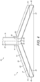
Figure 4 is a cross-sectional view of a suction tube and a further embodiment of the filter arrangement of the present disclosure; and -
Figure 5 is a perspective view of the filter arrangement ofFigure 4 . - The present disclosure is generally directed towards a filter arrangement of a reductant supply system for a selective catalytic reduction system. The filter arrangement comprises a restraining body and a filter mounted to a suction tube in a reductant liquid tank. The restraining body extends radially outwardly from the suction tube and over the filter. The restraining body prevents the filter from, under the effects of buoyancy of gas therein, floating upwardly above a tube inlet of the suction tube and is instead configured to direct the gas towards the tube inlet. As a result, any gas in the filter is removed early in the next operation cycle during a priming process.
-
Figure 1 illustrates an exemplary embodiment of anengine system 10 comprising thefilter arrangement 11 of the present disclosure. Theengine system 10 may be for providing power and/or drive to a machine. The machine may comprise a work machine or vehicle, such as an excavator, backhoe, articulated truck or the like. - The
engine system 10 comprises anengine 12 receiving air for anair intake 13, such as via aturbocharger 14 and/or supercharger 15. Theengine 12 may be an internal combustion engine, such as a compression-ignition or spark-ignition engine. Fuel, such as diesel, petrol or natural gas, may be selectively provided to engine cylinders in theengine 12 to combust with the intake air and drive the pistons, thereby rotating a crankshaft and providing an engine output torque and power. The by-product of the combustion process is exhaust gas, which may be directed from theengine 12 towards anexhaust 16 via anaftertreatment module 17 and optionally theturbocharger 14. Theengine system 10 may comprise any other suitable component, such as acooler 18 upstream of theengine 12, asupercharger bypass 19 and/or aturbine bypass 20. - The exhaust gas exiting the
engine 12 may comprise unwanted gaseous emissions or pollutants, such as nitrogen oxides (NOx), particulate matter (such as soot), sulphur oxides, carbon monoxide, unburnt hydrocarbons and/or other organic compounds. Theexhaust aftertreatment module 17 may receive and treat the exhaust gas to remove pollutants prior to directing the exhaust gas to atmosphere via theexhaust 16. Theexhaust aftertreatment module 17 may comprise a selective catalytic reduction orSCR system 25 and may comprise adiesel oxidation catalyst 24. Thediesel oxidation catalyst 24 may be arranged to receive exhaust gases from theengine 12 and may be located upstream of theSCR system 25. - The
SCR system 25, which is illustrated schematically inFigure 2 , may comprise anSCR catalyst arrangement 26 and areductant supply system 30. Thereductant supply system 30 may comprise areductant injector 31 for selectively injectingreductant liquid 32 into the exhaust gas directed from theengine 12, such as via theturbocharger 14 and/ordiesel oxidation catalyst 24. Thereductant injector 31 may injectreductant liquid 32 upstream of theSCR catalyst arrangement 26. - The
reductant liquid 32 may comprise aqueous urea, aqueous ammonia or the like. Thereductant liquid 32 may be diesel fluid (DEF) and the DEF may meet the ISO22241 standard and comprise from 31.8% to 33.2% urea by weight. Thereductant injector 31 may selectively inject thereductant liquid 32 into the stream of exhaust gas to provide a dose ofreductant liquid 32 to theSCR catalyst arrangement 26. The high exhaust gas temperature may cause thereductant liquid 32 to evaporate and the resulting combination of gases may contact a catalyst substrate in theSCR catalyst arrangement 26. Thereductant liquid 32 may react with the NOx in the exhaust gas to reduce it to nitrogen and water, which may pass out of theengine system 10 via theexhaust 16. - The
reductant supply system 30 comprises atank 33 for storingreductant liquid 32 and apump 34 in fluid communication with thetank 33 and thereductant injector 31. Thepump 34 is configured to drawreductant liquid 32 from thetank 33 and direct thereductant liquid 32 to thereductant injector 31. Thereductant supply system 30 comprises an outlet orsuction tube 35 at least partially mounted in thetank 33 and in fluid communication with thepump 34. Thesuction tube 35 may extend from inside thetank 33 to thepump 34 as illustrated or further conduits and/or valves may be located between thetank 33 andpump 34. - The
suction tube 35 comprises atube inlet 36 for receivingreductant liquid 32 from thetank 33. Thepump 34 may selectively drawreductant liquid 32 from thetank 33 through thetube inlet 36. Thesuction tube 35 may be configured to extend into thetank 33 such that thetube inlet 36 is below a predetermined level (for example, a minimum fill level below which theSCR system 25 is not operational) ofreductant liquid 32 therein when theSCR system 25 is operational. Thetube inlet 36 may be, in use, the lowest (i.e., lowest along the direction of gravity when theengine system 10 is level) point of suction of thesuction tube 35 as thepump 34 operates. - The
suction tube 35 may extend along alongitudinal axis 37 from a centre point of thetube inlet 36. In use, when theengine system 10 is in an upright position (such as when the machine it is mounted in is on level ground), thelongitudinal axis 37 is coaxial with the direction of gravity. Thesuction tube 35 may be configured such thatreductant liquid 32 may flow in a direction along thelongitudinal axis 37 when passing in or out of thetube inlet 36. - The
reductant supply system 30 further comprises thefilter arrangement 11 mounted to thesuction tube 35 and thefilter arrangement 11 is configured to filter thereductant liquid 32 prior to being drawn into thesuction tube 35 and out of thetank 33. Thefilter arrangement 11 ofFigure 2 is illustrated in further detail inFigure 3 . Thefilter arrangement 11 is mounted to thesuction tube 35 so as to cover thetube inlet 36. - The
filter arrangement 11 comprises a restrainingbody 40, afilter mount 41 mounting thefilter arrangement 11 to thesuction tube 35, afilter 42 mounted to the restrainingbody 40 and afilter outlet 44 formed through the restrainingbody 40 and/orfilter 42. - The
filter 42 is for filteringreductant liquid 32 drawn from thetank 33 into thefilter arrangement 11 by thepump 34. Substantially all reductant liquid 32 drawn from thetank 33 and directed to thereductant injector 31 by thepump 34 may pass through thefilter 42 prior to entry into thesuction tube 35. - The
filter 42 may be flexible, may comprise a flexible membrane, may comprise a filter fabric and/or may be more flexible than the restrainingbody 40. Thefilter 42 may be sufficiently flexible such that under the effects of the buoyancy of air therein, thefilter 42 may be inclined to change in shape, although the restrainingbody 40 may substantially prevent such a change in shape. Thefilter 42 may comprise a 2D or 3D filter and/or a mesh filter and may comprise multiple layers of materials bound together for filtration of thereductant liquid 32. - The
filter arrangement 11 comprises afilter chamber 45 formed at least partially by thefilter 42 and, optionally, by the restrainingbody 40 and/or filtermount 41. Fluid communicated between thesuction tube 35 andfilter 42 may pass through thefilter chamber 45. Thereductant liquid 32 may pass through thefilter chamber 45 after passing through thefilter 42 and prior to passing through thesuction tube 35 when thepump 34 draws reductant liquid 32 from thetank 33 to thereductant injector 31. - The
filter chamber 45 may be formed within thefilter 42 and thefilter 42 may surround thefilter chamber 45. Thefilter 42 may comprise at least onefilter wall lower filter walls Figure 2 , and thefilter chamber 45 may be enclosed therebetween. Thefilter 42 may form a pouch or bag as illustrated inFigures 1 and2 and may define thefilter chamber 45 within the pouch. - The
filter 42 may comprise or define afilter aperture 46 for liquid communication between thefilter chamber 45 and thesuction tube 35. Thefilter aperture 46 may extend through theupper filter wall 47 and may extend through the pouch. Thefilter aperture 46 may be configured to enable liquid communication between thefilter chamber 45 and thesuction tube 35. - The restraining
body 40 extends radially outwardly from thefilter mount 41 and thesuction tube 35 between aproximal body side 50 and adistal body side 51. The term "radially outwardly" may refer to aradial direction 55 perpendicular to the direction of gravity, perpendicular to thelongitudinal axis 37 of thesuction tube 35 and/or perpendicular to the (main) direction of flow of liquid entering or exiting thesuction tube 35 at thetube inlet 36. - The
proximal body side 50 may extend from adjacent to thesuction tube 35 and theproximal body side 50 of the restrainingbody 40 may be closest to thesuction tube 35 compared to thedistal body side 51. Thedistal body side 51 may be furthest from thesuction tube 35 and may face away from thesuction tube 35. In use, thedistal body side 51 may face downwardly into thetank 33 and theproximal body side 50 may face upwardly towards thesuction tube 35 and the top of thetank 33. - The restraining
body 40 may extend from abody aperture 52 to anouter body edge 53 between the proximal and distal body sides 50, 51. The proximal and distal body sides 50, 51 may comprise any suitable shape, such as rectangular as illustrated inFigures 2 and3 or conical as illustrated inFigures 4 and5 . - The restraining
body 40 may comprise a plate and/or be thin walled. The maximum width of the restrainingbody 40, which may be the maximum diameter or dimension across the proximal and distal body sides 50, 51 within theouter body edge 53 and across thebody aperture 52, may be substantially greater than the maximum thickness of the restrainingbody 40, which may be the dimension between the proximal and distal body sides 50, 51. In particular, the maximum width may be at least ten times greater than the maximum thickness. - The restraining
body 40 may be rigid and may be substantially more rigid than thefilter 42. The restrainingbody 40 may be configured to retain its shape regardless of its orientation and may be configured to restrain the shape of thefilter 42, which may be more flexible than the restrainingbody 40. The restrainingbody 40 may comprise a metal or plastic. - The
filter 42 may be attached or mounted to the restrainingbody 40. Thefilter 42 extends at least partially across thedistal body side 51 and may be mounted adjacent to and/or to thedistal body side 51. Thefilter 42 may be mounted on theother side 51 of the restrainingbody 40 to thesuction tube 35. The at least onefilter wall body 40, such as to thedistal body side 51, for example by adhesive. However, adhesive may not be necessary as air in thefilter 42 may push it towards the restrainingbody 40 and the restrainingbody 40 may restrict the upward movement of thefilter 42 due to buoyancy. Theupper filter wall 47 may be mounted to and extend across thedistal body side 51. Thefilter chamber 45 may separate the upper andlower filter walls filter 42 may comprise anouter filter edge 49, which may form the outer perimeter of thefilter 42 furthest from thefilter aperture 46,tube inlet 36,filter mount 41 and/orbody aperture 52. - The
outer filter edge 49 may extend between the upper andlower filter walls filter chamber 45 may be enclosed within the upper andlower filter walls outer filter edge 49. - The restraining
body 40 may extend radially outwardly to at least the entire outer perimeter of thefilter 42. The restrainingbody 40 may extend over theentire filter 42 and thefilter 42 may extend along thedistal body side 51 no further than theouter body edge 53. Thefilter 42 may be mounted to the restrainingbody 40 such that theouter filter edge 49 does not extend beyond theouter body edge 53. - The restraining
body 40 may comprise a mesh as illustrated inFigure 3 and may comprise a plurality ofmesh apertures 54 extending therethrough, such as between the proximal and distal body sides 50, 51. The mesh apertures 54 may be configured to allow fluid communication from thefilter 42, such as through theupper filter wall 47, at thedistal body side 51, through the restrainingbody 40 and beyond theproximal body side 50. In particular, themesh apertures 54 may be configured to allow gas trapped in thefilter 42 to escape from thefilter 42 and through the restrainingbody 40 via themesh apertures 54, such as under the effects of buoyancy. - The
filter mount 41 is for mounting thefilter arrangement 11 to thesuction tube 35 such that (a) thefilter chamber 45 is in fluid communication with thesuction tube 35 via thefilter outlet 44 and (b) thefilter 42 is on thedistal body side 51 of the restrainingbody 40 to thesuction tube 35. - The
filter mount 41 is mounted to the restrainingbody 40 and/orfilter 42. The filter mount 41 may be formed from the restrainingbody 40 and/or thefilter 42. As illustrated, the restrainingbody 40 may be mounted to thefilter mount 41 at thebody aperture 52, such as by thefilter mount 41 being mounted in and/or around thebody aperture 52. The filter mount 41 may be integrated with the restrainingbody 40 or thefilter 42 or may be a separate component attached thereto. - The filter mount 41 may comprise a
mount passageway 58 extending therethrough and thefilter aperture 46 may be mounted over the mount passageway 60. The filter mount 41 may be mounted to thesuction tube 35 such that the mount passageway 60 is in fluid communication with thetube inlet 36. Therefore, liquid may be drawn from thefilter chamber 45, through thefilter aperture 46 and into thesuction tube 35, such as via the mount passageway 60 andtube inlet 36. - The filter mount 41 may comprise a fastener, such as a thread on the inside of the mount passageway 60, for fastening to a reciprocal fastener, such as a thread, of the
suction tube 35. Alternatively, thefilter mount 41 may be mounted onto thesuction tube 35 by a push-fit connection. - The
filter outlet 44 extends from thefilter chamber 45 and is formed through the restrainingbody 40 and/orfilter 42. Thefilter outlet 44 may also extend through thefilter mount 41. Therefore, thefilter outlet 44 may comprise thefilter aperture 46, thebody aperture 52 and/or themount passageway 58, which may be aligned with each other as illustrated. Reductant liquid may communicate between thefilter chamber 45 and thesuction tube 35 through thefilter outlet 44. Thefilter outlet 44 may be configured to direct liquid along thelongitudinal axis 37 between thefilter chamber 45 and thesuction tube 35. - The restraining
body 40 extends radially outwardly from thefilter mount 41 and is configured to restrain thefilter 42 such that, under the effect of buoyancy in thetank 33 in use, gas in thefilter chamber 45 is directed towards thefilter outlet 44. Such buoyancy arises due to thefilter 42 being immersed inreductant liquid 32 in thetank 33. - In order to direct gas towards the
filter outlet 44, the restrainingbody 40 may depend downwardly from thesuction tube 35 and/or the restrainingbody 40 may extend radially outwardly at an acute angle to thelongitudinal axis 37 away from thefilter outlet 44. Thus the restrainingbody 40 may extend at an acute angle to thesuction tube 35. As a result, in use theentire filter chamber 45 is located below thefilter outlet 44 and thetube inlet 36 and gas travels up thefilter chamber 45 and into thefilter outlet 44. - Various alternative embodiments fall with the scope of the present disclosure.
Figures 4 and5 illustrate a further embodiment of thefilter arrangement 11 in which the restrainingbody 40 comprises a thin-walled cone, which may be truncated as shown at thefilter outlet 44. Gas in thefilter 42 may flow upwardly under buoyancy in thefilter chamber 45 towards the centre of the cone to exit through thefilter outlet 44, which is located at the tip of the cone. The term "thin-walled" refers to the distance between the proximal and distal body sides 50, 51 which may be less, such as at least ten times less, than the diameter or distance across the restrainingbody 40 within theouter body edge 53. Thefilter arrangement 11 may therefore be rotationally symmetric about thefilter outlet 44. In this embodiment thefilter 42 may comprise a pouch as illustrated entirely enclosing thefilter chamber 45 other than at thefilter outlet 44. The filter may also be shaped as a substantially thin-walled hollow cone as illustrated. - Furthermore, the restraining
body 40 may be solid and may not comprisemesh apertures 54 such that gas cannot escape therethrough. In such an arrangement thefilter 42 may not comprise anupper filter wall 47 extending across thedistal body side 51. Instead, a filter wall may be attached at or adjacent to theouter body edge 53 and extend across thedistal body side 51. Thefilter chamber 45 may be formed between filter wall and thedistal body side 51. - In further embodiments the
filter mount 41 may be integrated with thesuction tube 35 and thereductant supply system 30 may comprise the restrainingbody 40, thefilter mount 41 and thesuction tube 35 as a unitary component. - In use the
pump 34 is operated to draw reductant liquid 32 from thetank 33, through thefilter 42 into thefilter chamber 45, from thefilter chamber 45 through thefilter outlet 44, through thesuction tube 35 and to thereductant injector 31. Reductant liquid 32 may thus be selectively injected into the exhaust gas stream by thereductant injector 31. - At the end of an operating cycle a purge process may be run in which the
pump 34 is operated to draw anyreductant liquid 32 back from thereductant injector 31 and into thetank 33. However, in such a process air may also be drawn into thetank 33. Due to the construction of thefilter 42, much of the gas may be maintained within thefilter chamber 45. - It has been identified that a particular cause for air to remain in
flexible filters 42 after a purge process is that, by virtue of the buoyancy of the air in theflexible filters 42, thefilters 42 may be inclined to balloon upwardly around thetube inlet 36. This prevents the air from exiting thefilter 42 and the air may subsequently cause a failure in priming or aeration of thereductant liquid 32. - The present disclosure therefore overcomes such issues by the restraining
body 40 restricting thefilter 42 from rising above thetube inlet 36. The restrainingbody 40 therefore ensures that the whole of thefilter 42 is always below thetube inlet 36 and any air therein moves towards and through thetube inlet 36 after the purge is completed. During or after priming, in which thepump 34 draw reductant liquid 32 from thetank 33 towards thereductant injector 31, there is then no stored air in the filter that can be released, such as due to machine vibration. Any air in thereductant supply system 30 will be quickly driven therefore. - Furthermore, if the filter arrangement comprises
mesh apertures 54, any gas within thefilter chamber 45 may also be able to exit through theupper filter wall 47 and themesh apertures 54.
Claims (15)
- A filter arrangement for a reductant supply system of a selective catalytic reduction system, the reductant supply system comprising a tank and a suction tube mounted at least partially in the tank for receiving reductant liquid from the tank, wherein the filter arrangement comprises:a restraining body comprising a distal body side;a filter extending at least partially across the distal body side of the restraining body and at least partially forming a filter chamber;a filter outlet from the filter chamber formed through the restraining body and/or filter; anda filter mount mounted to the restraining body and/or filter, wherein the filter mount is for mounting the filter arrangement to the suction tube such that (a) the filter chamber is in fluid communication with the suction tube via the filter outlet and (b) the filter is on the distal body side of the restraining body to the suction tube,wherein the restraining body extends radially outwardly from the filter mount and is configured to restrain the filter such that, under the effect of buoyancy in the tank in use, gas in the filter chamber is directed towards the filter outlet.
- A filter arrangement as claimed in claim 1 wherein the restraining body extends radially outwardly to at least the entire outer perimeter of the filter.
- A filter arrangement as claimed in claim 1 or claim 2 wherein the filter outlet is configured to direct liquid along a longitudinal axis between the filter chamber and the suction tube and the restraining body extends radially outwardly at an acute angle to the longitudinal axis away from the filter outlet.
- A filter arrangement as claimed in any one of the preceding claims wherein the restraining body is more rigid than the filter.
- A filter arrangement as claimed in any one of the preceding claims wherein the restraining body comprises a plate or a thin-walled cone.
- A filter arrangement as claimed in any one of the preceding claims wherein the restraining body extends across a width between a proximal body side and the distal body side, wherein a thickness between the proximal and distal body sides is smaller than the width.
- A filter arrangement as claimed in any one of the preceding claims wherein the filter comprises a flexible membrane and/or filter fabric.
- A filter arrangement as claimed in any one of the preceding claims wherein the filter comprises at least one filter wall and the filter chamber is enclosed within the at least one filter wall.
- A filter arrangement as claimed in any one of the preceding claims wherein the filter comprises an upper filter wall attached to and extending at least partially across the distal body side.
- A filter arrangement as claimed in any one of the preceding claims wherein the restraining body comprises a plurality of mesh apertures extending therethrough and configured for fluid communication from the filter through the restraining body.
- A filter arrangement as claimed in any one of the preceding claims wherein the filter mount is integrated with the filter and/or the restraining body.
- A filter arrangement as claimed in any one of the preceding claims wherein the filter comprises a filter aperture therethrough, the restraining body comprises a body aperture therethrough and/or the filter mount comprises a mount passageway therethrough, wherein the filter outlet comprises the filter aperture, the body aperture and/or the mount passageway.
- A reductant supply system for a selective catalytic reduction system, the reductant supply system comprising:a tank for holding reductant liquid;a suction tube mounted at least partially in the tank for receiving reductant liquid from the tank; anda filter arrangement mounted to the suction tube, the filter arrangement comprising:a restraining body comprising a distal body side;a filter extending at least partially across the distal body side of the restraining body and at least partially forming a filter chamber;a filter outlet from the filter chamber formed through the restraining body and/or filter; anda filter mount mounted to the restraining body and/or filter such that (a) the filter chamber is in fluid communication with the suction tube via the filter outlet and (b) the filter is on the distal body side of the restraining body to the suction tube,wherein the restraining body extends radially outwardly from the filter mount and suction tube and is configured to restrain the filter such that, under the effect of buoyancy in the tank in use, gas in the filter chamber is directed towards the filter outlet.
- A reductant supply system of claim 12 wherein the suction tube extends along a longitudinal axis and the restraining body extends radially outwardly at an acute angle to the longitudinal axis.
- An engine system comprising an exhaust aftertreatment module for receiving exhaust gas from an internal combustion engine, the exhaust aftertreatment module comprising a selective catalytic reduction system, the selective catalytic reduction system comprising the reductant supply system of claim 13 or claim 14.
Applications Claiming Priority (1)
| Application Number | Priority Date | Filing Date | Title |
|---|---|---|---|
| GB2112379.9A GB2610228B (en) | 2021-08-31 | 2021-08-31 | A filter arrangement for a selective catalytic reduction system |
Publications (2)
| Publication Number | Publication Date |
|---|---|
| EP4144963A1 true EP4144963A1 (en) | 2023-03-08 |
| EP4144963B1 EP4144963B1 (en) | 2024-10-16 |
Family
ID=77999600
Family Applications (1)
| Application Number | Title | Priority Date | Filing Date |
|---|---|---|---|
| EP22186874.8A Active EP4144963B1 (en) | 2021-08-31 | 2022-07-26 | A filter arrangement for a selective catalytic reduction system |
Country Status (4)
| Country | Link |
|---|---|
| US (1) | US11801465B2 (en) |
| EP (1) | EP4144963B1 (en) |
| CN (1) | CN115721984A (en) |
| GB (1) | GB2610228B (en) |
Citations (3)
| Publication number | Priority date | Publication date | Assignee | Title |
|---|---|---|---|---|
| US20090294343A1 (en) * | 2008-05-29 | 2009-12-03 | Lev Pekarsky | Suction Filter for Automatic Transmission Fluid |
| WO2013079449A1 (en) * | 2011-11-30 | 2013-06-06 | Emitec Gesellschaft Für Emissionstechnologie Mbh | Device for providing reducing agent |
| EP2723998B1 (en) * | 2011-06-27 | 2015-10-14 | Kautex Textron GmbH & Co. KG. | Urea reservoir for a motor vehicle |
Family Cites Families (18)
| Publication number | Priority date | Publication date | Assignee | Title |
|---|---|---|---|---|
| FR2937877B1 (en) | 2008-10-31 | 2016-01-08 | Cummins Filtration Ip Inc | APPARATUS, SYSTEM AND METHOD FOR FILTRATION OF A DOSING FLUID IN A SECONDARY EXHAUST TREATMENT SYSTEM |
| DE102009000094A1 (en) * | 2009-01-09 | 2010-07-15 | Robert Bosch Gmbh | Tank for receiving an aqueous solution |
| US20110138790A1 (en) * | 2009-12-15 | 2011-06-16 | Delphi Technologies, Inc. | Urea Delivery Tank Module |
| FR2975013A1 (en) * | 2011-05-10 | 2012-11-16 | Filtertek | FLUID FILTRATION UNIT |
| US20130000760A1 (en) * | 2011-06-29 | 2013-01-03 | Ti Group Automotive Systems, L.L.C. | Fluid distribution system and components thereof |
| DE102012017288A1 (en) * | 2012-08-31 | 2014-03-06 | Hydac Filtertechnik Gmbh | Device for suction filtration of fluids |
| DE102013001237B4 (en) * | 2013-01-25 | 2015-04-16 | Kautex Textron Gmbh & Co. Kg | Filter device for a liquid container, in particular for aqueous urea solution |
| US9089791B2 (en) * | 2013-03-14 | 2015-07-28 | Cummins Ip, Inc. | Apparatus, method, and system for reductant filtration |
| US9377441B2 (en) | 2013-10-02 | 2016-06-28 | Ssi Technologies, Inc. | Reduction of aeration interference in an ultrasonic fluid sensing system |
| CN104040078B (en) | 2014-01-08 | 2016-01-20 | 株式会社小松制作所 | Reductant tank and working vehicle |
| US9248390B2 (en) | 2014-01-14 | 2016-02-02 | Caterpillar Inc. | Filter system and filtration method for fluid reservoirs |
| US20150218990A1 (en) * | 2014-02-03 | 2015-08-06 | Caterpillar Inc. | Diesel exhaust fluid filter permeability detection strategy and machine using same |
| US20170189837A1 (en) * | 2016-01-06 | 2017-07-06 | Caterpillar Inc. | Filter System and Filtration Method for Fluid Reservoirs |
| CN105909351A (en) * | 2016-05-31 | 2016-08-31 | 苏州新力迈特汽车系统有限公司 | Urea filter for automobile SCR post-processing system |
| US10371030B2 (en) | 2016-09-30 | 2019-08-06 | Deere & Company | Diesel exhaust fluid system |
| DE102017212768A1 (en) * | 2017-07-25 | 2019-01-31 | Robert Bosch Gmbh | Liquid filter and tank filter system with a liquid filter |
| CN113226508B (en) | 2018-07-30 | 2023-03-17 | 肖恩发展有限责任公司 | Aqueous fluid filter assembly with aeration mitigation |
| DE102019202136A1 (en) * | 2019-02-18 | 2020-08-20 | Siemens Mobility GmbH | Arrangement for filtering liquids |
-
2021
- 2021-08-31 GB GB2112379.9A patent/GB2610228B/en active Active
-
2022
- 2022-07-26 EP EP22186874.8A patent/EP4144963B1/en active Active
- 2022-08-24 CN CN202211018409.7A patent/CN115721984A/en active Pending
- 2022-08-31 US US17/899,969 patent/US11801465B2/en active Active
Patent Citations (3)
| Publication number | Priority date | Publication date | Assignee | Title |
|---|---|---|---|---|
| US20090294343A1 (en) * | 2008-05-29 | 2009-12-03 | Lev Pekarsky | Suction Filter for Automatic Transmission Fluid |
| EP2723998B1 (en) * | 2011-06-27 | 2015-10-14 | Kautex Textron GmbH & Co. KG. | Urea reservoir for a motor vehicle |
| WO2013079449A1 (en) * | 2011-11-30 | 2013-06-06 | Emitec Gesellschaft Für Emissionstechnologie Mbh | Device for providing reducing agent |
Also Published As
| Publication number | Publication date |
|---|---|
| EP4144963B1 (en) | 2024-10-16 |
| GB202112379D0 (en) | 2021-10-13 |
| GB2610228A (en) | 2023-03-01 |
| GB2610228B (en) | 2023-08-23 |
| US20230060731A1 (en) | 2023-03-02 |
| CN115721984A (en) | 2023-03-03 |
| US11801465B2 (en) | 2023-10-31 |
Similar Documents
| Publication | Publication Date | Title |
|---|---|---|
| JP5090890B2 (en) | Engine exhaust purification system | |
| JP5610120B2 (en) | Engine exhaust purification system | |
| CN101646845B (en) | Exhaust gas purification apparatus for internal combustion engine | |
| CN205001033U (en) | Reductant supply system | |
| EP2489844A1 (en) | Exhaust purification device for engine | |
| JP4280934B2 (en) | Exhaust purification device, additive supply device, and exhaust purification system for internal combustion engine | |
| US20150023843A1 (en) | Reductant supply system | |
| US20160298515A1 (en) | Method of Controlling an Engine System | |
| CN104234801A (en) | An exhaust gas sampling device | |
| JP4216673B2 (en) | Exhaust purification equipment | |
| US20090100827A1 (en) | Exhaust gas purification apparatus for internal combustion engine | |
| JP5166848B2 (en) | Exhaust purification device | |
| JP4861974B2 (en) | Engine exhaust purification system | |
| US11801465B2 (en) | Filter arrangement for a selective catalytic reduction system | |
| JP5924491B2 (en) | Exhaust gas purification device for internal combustion engine | |
| US8919108B2 (en) | Exhaust gas temperature raising apparatus and a method for removal of fuel supply valve clogging | |
| JP4737143B2 (en) | Exhaust gas purification device for internal combustion engine | |
| US10400650B2 (en) | Injector deposit dissolution system and method | |
| JP2017218931A (en) | Exhaust emission control device for vehicle | |
| JP2009097435A (en) | Exhaust emission control device | |
| JP2010031717A (en) | Exhaust emission control device | |
| KR102222447B1 (en) | Exhaust Gas Reduction Device and Control Method of Exhaust Gas Reduction Device | |
| EP2508724A1 (en) | Engine exhaust-air purifying apparatus | |
| KR101461875B1 (en) | Exhaust gas purification device | |
| CN103842622B (en) | The turbine of boosting explosive motor cleans |
Legal Events
| Date | Code | Title | Description |
|---|---|---|---|
| PUAI | Public reference made under article 153(3) epc to a published international application that has entered the european phase |
Free format text: ORIGINAL CODE: 0009012 |
|
| STAA | Information on the status of an ep patent application or granted ep patent |
Free format text: STATUS: THE APPLICATION HAS BEEN PUBLISHED |
|
| AK | Designated contracting states |
Kind code of ref document: A1 Designated state(s): AL AT BE BG CH CY CZ DE DK EE ES FI FR GB GR HR HU IE IS IT LI LT LU LV MC MK MT NL NO PL PT RO RS SE SI SK SM TR |
|
| STAA | Information on the status of an ep patent application or granted ep patent |
Free format text: STATUS: REQUEST FOR EXAMINATION WAS MADE |
|
| 17P | Request for examination filed |
Effective date: 20230901 |
|
| RBV | Designated contracting states (corrected) |
Designated state(s): AL AT BE BG CH CY CZ DE DK EE ES FI FR GB GR HR HU IE IS IT LI LT LU LV MC MK MT NL NO PL PT RO RS SE SI SK SM TR |
|
| GRAP | Despatch of communication of intention to grant a patent |
Free format text: ORIGINAL CODE: EPIDOSNIGR1 |
|
| STAA | Information on the status of an ep patent application or granted ep patent |
Free format text: STATUS: GRANT OF PATENT IS INTENDED |
|
| INTG | Intention to grant announced |
Effective date: 20240426 |
|
| GRAS | Grant fee paid |
Free format text: ORIGINAL CODE: EPIDOSNIGR3 |
|
| P01 | Opt-out of the competence of the unified patent court (upc) registered |
Free format text: CASE NUMBER: APP_41885/2024 Effective date: 20240716 |
|
| GRAA | (expected) grant |
Free format text: ORIGINAL CODE: 0009210 |
|
| STAA | Information on the status of an ep patent application or granted ep patent |
Free format text: STATUS: THE PATENT HAS BEEN GRANTED |
|
| AK | Designated contracting states |
Kind code of ref document: B1 Designated state(s): AL AT BE BG CH CY CZ DE DK EE ES FI FR GB GR HR HU IE IS IT LI LT LU LV MC MK MT NL NO PL PT RO RS SE SI SK SM TR |
|
| REG | Reference to a national code |
Ref country code: GB Ref legal event code: FG4D |
|
| REG | Reference to a national code |
Ref country code: DE Ref legal event code: R096 Ref document number: 602022006819 Country of ref document: DE Ref country code: CH Ref legal event code: EP |
|
| REG | Reference to a national code |
Ref country code: IE Ref legal event code: FG4D |
|
| REG | Reference to a national code |
Ref country code: LT Ref legal event code: MG9D |
|
| REG | Reference to a national code |
Ref country code: NL Ref legal event code: MP Effective date: 20241016 |
|
| REG | Reference to a national code |
Ref country code: AT Ref legal event code: MK05 Ref document number: 1733068 Country of ref document: AT Kind code of ref document: T Effective date: 20241016 |
|
| PG25 | Lapsed in a contracting state [announced via postgrant information from national office to epo] |
Ref country code: NL Free format text: LAPSE BECAUSE OF FAILURE TO SUBMIT A TRANSLATION OF THE DESCRIPTION OR TO PAY THE FEE WITHIN THE PRESCRIBED TIME-LIMIT Effective date: 20241016 |
|
| PG25 | Lapsed in a contracting state [announced via postgrant information from national office to epo] |
Ref country code: NL Free format text: LAPSE BECAUSE OF FAILURE TO SUBMIT A TRANSLATION OF THE DESCRIPTION OR TO PAY THE FEE WITHIN THE PRESCRIBED TIME-LIMIT Effective date: 20241016 |
|
| PG25 | Lapsed in a contracting state [announced via postgrant information from national office to epo] |
Ref country code: PT Free format text: LAPSE BECAUSE OF FAILURE TO SUBMIT A TRANSLATION OF THE DESCRIPTION OR TO PAY THE FEE WITHIN THE PRESCRIBED TIME-LIMIT Effective date: 20250217 Ref country code: IS Free format text: LAPSE BECAUSE OF FAILURE TO SUBMIT A TRANSLATION OF THE DESCRIPTION OR TO PAY THE FEE WITHIN THE PRESCRIBED TIME-LIMIT Effective date: 20250216 Ref country code: HR Free format text: LAPSE BECAUSE OF FAILURE TO SUBMIT A TRANSLATION OF THE DESCRIPTION OR TO PAY THE FEE WITHIN THE PRESCRIBED TIME-LIMIT Effective date: 20241016 |
|
| PG25 | Lapsed in a contracting state [announced via postgrant information from national office to epo] |
Ref country code: FI Free format text: LAPSE BECAUSE OF FAILURE TO SUBMIT A TRANSLATION OF THE DESCRIPTION OR TO PAY THE FEE WITHIN THE PRESCRIBED TIME-LIMIT Effective date: 20241016 |
|
| PG25 | Lapsed in a contracting state [announced via postgrant information from national office to epo] |
Ref country code: BG Free format text: LAPSE BECAUSE OF FAILURE TO SUBMIT A TRANSLATION OF THE DESCRIPTION OR TO PAY THE FEE WITHIN THE PRESCRIBED TIME-LIMIT Effective date: 20241016 |
|
| PG25 | Lapsed in a contracting state [announced via postgrant information from national office to epo] |
Ref country code: ES Free format text: LAPSE BECAUSE OF FAILURE TO SUBMIT A TRANSLATION OF THE DESCRIPTION OR TO PAY THE FEE WITHIN THE PRESCRIBED TIME-LIMIT Effective date: 20241016 |
|
| PG25 | Lapsed in a contracting state [announced via postgrant information from national office to epo] |
Ref country code: NO Free format text: LAPSE BECAUSE OF FAILURE TO SUBMIT A TRANSLATION OF THE DESCRIPTION OR TO PAY THE FEE WITHIN THE PRESCRIBED TIME-LIMIT Effective date: 20250116 |
|
| PG25 | Lapsed in a contracting state [announced via postgrant information from national office to epo] |
Ref country code: AT Free format text: LAPSE BECAUSE OF FAILURE TO SUBMIT A TRANSLATION OF THE DESCRIPTION OR TO PAY THE FEE WITHIN THE PRESCRIBED TIME-LIMIT Effective date: 20241016 Ref country code: GR Free format text: LAPSE BECAUSE OF FAILURE TO SUBMIT A TRANSLATION OF THE DESCRIPTION OR TO PAY THE FEE WITHIN THE PRESCRIBED TIME-LIMIT Effective date: 20250117 Ref country code: LV Free format text: LAPSE BECAUSE OF FAILURE TO SUBMIT A TRANSLATION OF THE DESCRIPTION OR TO PAY THE FEE WITHIN THE PRESCRIBED TIME-LIMIT Effective date: 20241016 |
|
| PG25 | Lapsed in a contracting state [announced via postgrant information from national office to epo] |
Ref country code: PL Free format text: LAPSE BECAUSE OF FAILURE TO SUBMIT A TRANSLATION OF THE DESCRIPTION OR TO PAY THE FEE WITHIN THE PRESCRIBED TIME-LIMIT Effective date: 20241016 |
|
| PG25 | Lapsed in a contracting state [announced via postgrant information from national office to epo] |
Ref country code: RS Free format text: LAPSE BECAUSE OF FAILURE TO SUBMIT A TRANSLATION OF THE DESCRIPTION OR TO PAY THE FEE WITHIN THE PRESCRIBED TIME-LIMIT Effective date: 20250116 |
|
| PG25 | Lapsed in a contracting state [announced via postgrant information from national office to epo] |
Ref country code: SM Free format text: LAPSE BECAUSE OF FAILURE TO SUBMIT A TRANSLATION OF THE DESCRIPTION OR TO PAY THE FEE WITHIN THE PRESCRIBED TIME-LIMIT Effective date: 20241016 |
|
| PG25 | Lapsed in a contracting state [announced via postgrant information from national office to epo] |
Ref country code: DK Free format text: LAPSE BECAUSE OF FAILURE TO SUBMIT A TRANSLATION OF THE DESCRIPTION OR TO PAY THE FEE WITHIN THE PRESCRIBED TIME-LIMIT Effective date: 20241016 |
|
| REG | Reference to a national code |
Ref country code: DE Ref legal event code: R097 Ref document number: 602022006819 Country of ref document: DE |
|
| PG25 | Lapsed in a contracting state [announced via postgrant information from national office to epo] |
Ref country code: EE Free format text: LAPSE BECAUSE OF FAILURE TO SUBMIT A TRANSLATION OF THE DESCRIPTION OR TO PAY THE FEE WITHIN THE PRESCRIBED TIME-LIMIT Effective date: 20241016 |
|
| PGFP | Annual fee paid to national office [announced via postgrant information from national office to epo] |
Ref country code: FR Payment date: 20250620 Year of fee payment: 4 |
|
| PG25 | Lapsed in a contracting state [announced via postgrant information from national office to epo] |
Ref country code: RO Free format text: LAPSE BECAUSE OF FAILURE TO SUBMIT A TRANSLATION OF THE DESCRIPTION OR TO PAY THE FEE WITHIN THE PRESCRIBED TIME-LIMIT Effective date: 20241016 |
|
| PG25 | Lapsed in a contracting state [announced via postgrant information from national office to epo] |
Ref country code: SK Free format text: LAPSE BECAUSE OF FAILURE TO SUBMIT A TRANSLATION OF THE DESCRIPTION OR TO PAY THE FEE WITHIN THE PRESCRIBED TIME-LIMIT Effective date: 20241016 |
|
| PGFP | Annual fee paid to national office [announced via postgrant information from national office to epo] |
Ref country code: TR Payment date: 20250627 Year of fee payment: 4 |
|
| PG25 | Lapsed in a contracting state [announced via postgrant information from national office to epo] |
Ref country code: CZ Free format text: LAPSE BECAUSE OF FAILURE TO SUBMIT A TRANSLATION OF THE DESCRIPTION OR TO PAY THE FEE WITHIN THE PRESCRIBED TIME-LIMIT Effective date: 20241016 |
|
| PG25 | Lapsed in a contracting state [announced via postgrant information from national office to epo] |
Ref country code: IT Free format text: LAPSE BECAUSE OF FAILURE TO SUBMIT A TRANSLATION OF THE DESCRIPTION OR TO PAY THE FEE WITHIN THE PRESCRIBED TIME-LIMIT Effective date: 20241016 |
|
| PLBE | No opposition filed within time limit |
Free format text: ORIGINAL CODE: 0009261 |
|
| STAA | Information on the status of an ep patent application or granted ep patent |
Free format text: STATUS: NO OPPOSITION FILED WITHIN TIME LIMIT |
|
| PG25 | Lapsed in a contracting state [announced via postgrant information from national office to epo] |
Ref country code: SE Free format text: LAPSE BECAUSE OF FAILURE TO SUBMIT A TRANSLATION OF THE DESCRIPTION OR TO PAY THE FEE WITHIN THE PRESCRIBED TIME-LIMIT Effective date: 20241016 |
|
| 26N | No opposition filed |
Effective date: 20250717 |
|
| PGFP | Annual fee paid to national office [announced via postgrant information from national office to epo] |
Ref country code: DE Payment date: 20250620 Year of fee payment: 4 |
|
| REG | Reference to a national code |
Ref country code: CH Ref legal event code: H13 Free format text: ST27 STATUS EVENT CODE: U-0-0-H10-H13 (AS PROVIDED BY THE NATIONAL OFFICE) Effective date: 20260224 |
|
| PG25 | Lapsed in a contracting state [announced via postgrant information from national office to epo] |
Ref country code: LU Free format text: LAPSE BECAUSE OF NON-PAYMENT OF DUE FEES Effective date: 20250726 |
|
| REG | Reference to a national code |
Ref country code: BE Ref legal event code: MM Effective date: 20250731 |
|
| PG25 | Lapsed in a contracting state [announced via postgrant information from national office to epo] |
Ref country code: BE Free format text: LAPSE BECAUSE OF NON-PAYMENT OF DUE FEES Effective date: 20250731 |
|
| PG25 | Lapsed in a contracting state [announced via postgrant information from national office to epo] |
Ref country code: CH Free format text: LAPSE BECAUSE OF NON-PAYMENT OF DUE FEES Effective date: 20250731 |