EP4144960A1 - Fluid machine for an aircraft engine and aircraft engine - Google Patents
Fluid machine for an aircraft engine and aircraft engine Download PDFInfo
- Publication number
- EP4144960A1 EP4144960A1 EP22193989.5A EP22193989A EP4144960A1 EP 4144960 A1 EP4144960 A1 EP 4144960A1 EP 22193989 A EP22193989 A EP 22193989A EP 4144960 A1 EP4144960 A1 EP 4144960A1
- Authority
- EP
- European Patent Office
- Prior art keywords
- depression
- central axis
- wall
- stator
- taken along
- Prior art date
- Legal status (The legal status is an assumption and is not a legal conclusion. Google has not performed a legal analysis and makes no representation as to the accuracy of the status listed.)
- Pending
Links
- 239000012530 fluid Substances 0.000 title claims abstract description 19
- 238000011144 upstream manufacturing Methods 0.000 claims abstract description 17
- 230000004323 axial length Effects 0.000 claims description 16
- 238000004891 communication Methods 0.000 claims description 5
- 239000007789 gas Substances 0.000 description 16
- 239000003570 air Substances 0.000 description 4
- 230000006835 compression Effects 0.000 description 3
- 238000007906 compression Methods 0.000 description 3
- 238000009792 diffusion process Methods 0.000 description 3
- 238000005516 engineering process Methods 0.000 description 3
- 239000000567 combustion gas Substances 0.000 description 2
- 238000012986 modification Methods 0.000 description 2
- 230000004048 modification Effects 0.000 description 2
- 239000012080 ambient air Substances 0.000 description 1
- 230000009977 dual effect Effects 0.000 description 1
- 239000000446 fuel Substances 0.000 description 1
- 239000000203 mixture Substances 0.000 description 1
- 238000000926 separation method Methods 0.000 description 1
Images
Classifications
-
- F—MECHANICAL ENGINEERING; LIGHTING; HEATING; WEAPONS; BLASTING
- F01—MACHINES OR ENGINES IN GENERAL; ENGINE PLANTS IN GENERAL; STEAM ENGINES
- F01D—NON-POSITIVE DISPLACEMENT MACHINES OR ENGINES, e.g. STEAM TURBINES
- F01D5/00—Blades; Blade-carrying members; Heating, heat-insulating, cooling or antivibration means on the blades or the members
- F01D5/12—Blades
- F01D5/14—Form or construction
- F01D5/141—Shape, i.e. outer, aerodynamic form
- F01D5/142—Shape, i.e. outer, aerodynamic form of the blades of successive rotor or stator blade-rows
- F01D5/143—Contour of the outer or inner working fluid flow path wall, i.e. shroud or hub contour
-
- F—MECHANICAL ENGINEERING; LIGHTING; HEATING; WEAPONS; BLASTING
- F01—MACHINES OR ENGINES IN GENERAL; ENGINE PLANTS IN GENERAL; STEAM ENGINES
- F01D—NON-POSITIVE DISPLACEMENT MACHINES OR ENGINES, e.g. STEAM TURBINES
- F01D9/00—Stators
- F01D9/02—Nozzles; Nozzle boxes; Stator blades; Guide conduits, e.g. individual nozzles
- F01D9/04—Nozzles; Nozzle boxes; Stator blades; Guide conduits, e.g. individual nozzles forming ring or sector
- F01D9/041—Nozzles; Nozzle boxes; Stator blades; Guide conduits, e.g. individual nozzles forming ring or sector using blades
-
- F—MECHANICAL ENGINEERING; LIGHTING; HEATING; WEAPONS; BLASTING
- F01—MACHINES OR ENGINES IN GENERAL; ENGINE PLANTS IN GENERAL; STEAM ENGINES
- F01D—NON-POSITIVE DISPLACEMENT MACHINES OR ENGINES, e.g. STEAM TURBINES
- F01D5/00—Blades; Blade-carrying members; Heating, heat-insulating, cooling or antivibration means on the blades or the members
- F01D5/12—Blades
- F01D5/14—Form or construction
- F01D5/141—Shape, i.e. outer, aerodynamic form
- F01D5/146—Shape, i.e. outer, aerodynamic form of blades with tandem configuration, split blades or slotted blades
-
- F—MECHANICAL ENGINEERING; LIGHTING; HEATING; WEAPONS; BLASTING
- F05—INDEXING SCHEMES RELATING TO ENGINES OR PUMPS IN VARIOUS SUBCLASSES OF CLASSES F01-F04
- F05D—INDEXING SCHEME FOR ASPECTS RELATING TO NON-POSITIVE-DISPLACEMENT MACHINES OR ENGINES, GAS-TURBINES OR JET-PROPULSION PLANTS
- F05D2220/00—Application
- F05D2220/30—Application in turbines
- F05D2220/32—Application in turbines in gas turbines
- F05D2220/323—Application in turbines in gas turbines for aircraft propulsion, e.g. jet engines
-
- F—MECHANICAL ENGINEERING; LIGHTING; HEATING; WEAPONS; BLASTING
- F05—INDEXING SCHEMES RELATING TO ENGINES OR PUMPS IN VARIOUS SUBCLASSES OF CLASSES F01-F04
- F05D—INDEXING SCHEME FOR ASPECTS RELATING TO NON-POSITIVE-DISPLACEMENT MACHINES OR ENGINES, GAS-TURBINES OR JET-PROPULSION PLANTS
- F05D2240/00—Components
- F05D2240/10—Stators
- F05D2240/12—Fluid guiding means, e.g. vanes
- F05D2240/121—Fluid guiding means, e.g. vanes related to the leading edge of a stator vane
-
- F—MECHANICAL ENGINEERING; LIGHTING; HEATING; WEAPONS; BLASTING
- F05—INDEXING SCHEMES RELATING TO ENGINES OR PUMPS IN VARIOUS SUBCLASSES OF CLASSES F01-F04
- F05D—INDEXING SCHEME FOR ASPECTS RELATING TO NON-POSITIVE-DISPLACEMENT MACHINES OR ENGINES, GAS-TURBINES OR JET-PROPULSION PLANTS
- F05D2240/00—Components
- F05D2240/10—Stators
- F05D2240/12—Fluid guiding means, e.g. vanes
- F05D2240/124—Fluid guiding means, e.g. vanes related to the suction side of a stator vane
-
- F—MECHANICAL ENGINEERING; LIGHTING; HEATING; WEAPONS; BLASTING
- F05—INDEXING SCHEMES RELATING TO ENGINES OR PUMPS IN VARIOUS SUBCLASSES OF CLASSES F01-F04
- F05D—INDEXING SCHEME FOR ASPECTS RELATING TO NON-POSITIVE-DISPLACEMENT MACHINES OR ENGINES, GAS-TURBINES OR JET-PROPULSION PLANTS
- F05D2250/00—Geometry
- F05D2250/70—Shape
- F05D2250/71—Shape curved
- F05D2250/712—Shape curved concave
-
- Y—GENERAL TAGGING OF NEW TECHNOLOGICAL DEVELOPMENTS; GENERAL TAGGING OF CROSS-SECTIONAL TECHNOLOGIES SPANNING OVER SEVERAL SECTIONS OF THE IPC; TECHNICAL SUBJECTS COVERED BY FORMER USPC CROSS-REFERENCE ART COLLECTIONS [XRACs] AND DIGESTS
- Y02—TECHNOLOGIES OR APPLICATIONS FOR MITIGATION OR ADAPTATION AGAINST CLIMATE CHANGE
- Y02T—CLIMATE CHANGE MITIGATION TECHNOLOGIES RELATED TO TRANSPORTATION
- Y02T50/00—Aeronautics or air transport
- Y02T50/60—Efficient propulsion technologies, e.g. for aircraft
Definitions
- the application relates generally to aircraft engines, such as gas turbine engines and, more particularly, to compressors and turbines of such engines.
- Aircraft engines such as gas turbine engines, comprise compressors that include one or more compressor stage.
- a typical compressor stage includes a stator having vanes and a rotor having blades.
- the rotor is rotatable relative to the stator.
- the stator is used to orient the flow such that the flow exiting the stator meets leading edges of the blades at an optimal angle of attack. In some operating conditions, the stator exhibit corner losses and secondary flows that may impair performance. Hence, improvements are sought.
- a fluid machine for an aircraft engine comprising: a first wall and a second wall circumferentially extending around a central axis; a gaspath defined between the first wall and the second wall; a rotor having blades circumferentially distributed around the central axis and extending cross the gaspath, the rotor rotatable about the central axis; and a stator in fluid communication with the rotor and having: a row of vanes extending across the gaspath and circumferentially distributed around the central axis, the vanes having airfoils including leading edges, trailing edges, pressure sides and suction sides opposed the pressure sides, and depressions defined in the first wall, the depressions extending from a baseline surface of the first wall away from the second wall, a depression of the depressions located circumferentially between a pressure side of the pressure sides and a suction side of the suction sides, the depression axially overlapping the airfoils and located closer to the suction side than to the pressure side, an up
- the fluid machine may include any of the following features, in any combinations.
- a ratio of an axial length (h) of the depression taken along an axial direction relative to the central axis to an axial length (C) of the stator taken along the axial direction from the leading edges to the trailing edges ranges from 0.1 to 0.75.
- a ratio of a thickness (t) of the depression taken along a circumferential direction relative to the central axis to a pitch (p) of the stator extending along the circumferential direction from the leading edge of to an adjacent leading edge of the leading edges ranges from 0.05 to 0.5.
- a ratio of a distance (h1) taken along an axial direction relative to the central axis from the upstream end of the depression to the leading edge to an axial length (C) of the stator taken along the axial direction from the leading edges to the trailing edges ranges from -0.25 to 0.25.
- a ratio of a distance (h2) taken along an axial direction relative to the central axis from a downstream end of the depression to a trailing edge of the trailing edges to an axial length (C) of the stator taken along the axial direction from the leading edges to the trailing edges ranges from 0.25 to 0.75.
- a ratio of a depth (D) of the depression taken along a radial direction relative to the central axis to a span (S) of the airfoils ranges from 0.05 to 0.1.
- a thickness (t) of the depression taken along a circumferential direction relative to the central axis increases along a flow direction of a flow flowing between the airfoils.
- the depression is located closer to the suction side than to the pressure side.
- the depression extends substantially parallel to the suction side.
- the depression intersect a throat extending from the leading edge to an adjacent suction side of the suction sides.
- an aircraft engine comprising: a compressor section having: a first wall and a second wall circumferentially extending around a central axis; a gaspath defined between the first wall and the second wall; a rotor having blades circumferentially distributed around the central axis and extending across the gaspath, the rotor rotatable about the central axis; and a stator in fluid communication with the rotor and having: a row of vanes extending across the gaspath and circumferentially distributed around the central axis, the vanes having airfoils including leading edges, trailing edges, pressure sides and suction sides opposed the pressure sides, and depressions defined in the first wall, the depressions extending from a baseline surface of the first wall away from the second wall, a depression of the depressions located circumferentially between a pressure side of the pressure sides and a suction side of the suction sides, the depression axially overlapping the airfoils and closer to the suction side than to the pressure side, an up
- the aircraft engine may include any of the following features, in any combinations.
- a ratio of an axial length (h) of the depression taken along an axial direction relative to the central axis to an axial length (C) of the stator taken along the axial direction from the leading edges to the trailing edges ranges from 0.1 to 0.75.
- a ratio of a thickness (t) of the depression taken along a circumferential direction relative to the central axis to a pitch (p) of the stator extending along the circumferential direction from a leading edge of the leading edges to an adjacent leading edge of the leading edges ranges from 0.05 to 0.5.
- a ratio of a distance (h1) taken along the axial direction from the upstream end of the depression to the leading edge to the axial length (C) of the stator ranges from -0.25 to 0.25.
- a ratio of a distance (h2) taken along the axial direction from a downstream end of the depression to a trailing edge of the trailing edges to the axial length (C) of the stator ranges from 0.25 to 0.75.
- a ratio of a depth (D) of the depression taken along a radial direction relative to the central axis to a span (S) of the airfoils ranges from 0.05 to 0.1.
- the thickness of the depression increases along a flow direction of a flow flowing between the airfoils.
- the depression is located closer to the suction side than to the pressure side.
- the depression extends substantially parallel to the suction side.
- the depression intersects a throat extending from the leading edge to an adjacent suction side of the suction sides.
- Fig. 1 illustrates an aircraft engine depicted as a gas turbine engine 10 of a type preferably provided for use in subsonic flight, generally comprising in serial flow communication a fan 12, a compressor section 14 for pressurizing the air, a combustor 16 in which the compressed air is mixed with fuel and ignited for generating an annular stream of hot combustion gases, and a turbine section 18 for extracting energy from the combustion gases.
- the fan 12, the compressor section 14, and the turbine section 18 are rotatable about a central axis 11 of the gas turbine engine 10.
- the principles of the present disclosure may apply to any gas turbine engine such as turboprop and turboshaft gas turbine engines.
- the compressor section 14 includes one or more compressor rotors 22 and stators 24 in fluid communication with the rotors 22.
- the exemplary gas turbine engine 10 of Fig. 1 is a turbofan engine including the fan 12 through which ambient air is propelled. An airflow flowing between blades of the fan 12 is split between an engine core gaspath 15 and a bypass flow path 17 downstream of the fan 12.
- the gas turbine engine 10 has an engine casing 20 that circumferentially extends around the central axis 11. The core gaspath 15 is therefore located radially inwardly of the engine casing 20 relative to the central axis 11 and the bypass flow path 17 located radially outwardly of the engine casing 20 relative to the central axis 11.
- the compressor section 14 of the gas turbine engine 10 includes at least one compression stage having a tandem stator assembly 30 (which may be alternately referred to as a dual stator assembly), composed of two individual stators, namely a first stator 31 and a second stator 32 in immediate flow-wise succession (i.e. without any rotor therebetween); the second stator 32 located downstream of the first stator 31 relative to the air flow flowing in the core gaspath 15.
- the tandem stator assembly 30 is shown as being part of the first compression stage, that is it is located downstream of the fan 12 at the inlet of a core of the engine 10 and within the engine core gaspath 15.
- tandem stator assembly 30 may form part of other compression stages, such as those further downstream within the core of the gas turbine engine 10, either instead of or addition to being immediately downstream from the fan 12.
- the tandem stator assembly 30 may be used in a turbine stage of the turbine section 18.
- the tandem stator 30 may be used in the bypass flow path 17.
- the core gaspath 15 is defined radially between an inner gaspath wall 21A, which may include vane platforms (not shown), and an outer gaspath wall 21B, which may include vane shroud (not shown).
- the outer gaspath wall 21B is located radially outwardly of the inner gaspath wall 21A relative to the central axis 11.
- the first stator 31 includes a first row of a plurality of first vanes 33 and the second stator 32 includes a second row of a plurality of second vanes 34.
- the first vanes 33 and the second vanes 34 are circumferentially distributed around the central axis 11.
- the first vanes 33 may be staggered relative to the second vanes 34.
- a circumferential position of each of the first vanes 33 may be between circumferential positions of two circumferentially adjacent ones of the second vanes 34.
- the first vanes 33 extend from first inner ends 33A at the inner gaspath wall 21A to first outer ends 33B at the outer gaspath wall 21B.
- the second vanes 34 extend from second inner ends 34A at the inner gaspath wall 21A to second outer ends 34B at the outer gaspath wall 21B.
- the first vanes 33 include first airfoils 35 having first leading edges 35A, first trailing edges 35B downstream of the first leading edges 35A, first pressure sides 35C ( Fig. 3 ), and first suction sides 35D ( Fig. 3 ) opposed the first pressure sides 35C.
- the first airfoils 35 extend in a direction having a radial component relative to the central axis 11 from the inner gaspath wall 21A to the outer gaspath wall 21B.
- the second vanes 34 include second airfoils 36 that extend in a direction having a radial component relative to the central axis 11 from the inner gaspath wall 21A to the outer gaspath wall 21B.
- the second airfoils 36 have second leading edges 36A, second trailing edges 36B downstream of the second leading edges 36A, second pressure sides, and second suction sides opposed the second pressure sides.
- the first airfoils 35 are offset from the second airfoils 36 such that the second leading edges 36A are located downstream of the first trailing edges 35B relative to the air flow flowing in the core gaspath 15. An axial offset is therefore defined between the second leading edges 36A and the first trailing edges 35B.
- the first airfoils 35 may be at least partially axially overlapped by the second airfoils 36 such that the second leading edges 36A are located upstream of the first trailing edges 35B.
- the second leading edges 36A may be axially aligned with the first trailing edges 35B.
- stator e.g., first stator 31, second stator 32, stator 24
- corner loss may occur as a result of boundary layer build up.
- Large boundary layer build up toward trailing edges of the stator on suction sides may lead to high flow deviation and potential corner separation due to additional pressure side flow leakage across the trailing edge. This may result in flow deviation and wake shedding, which is undesirable.
- the tandem stator 30 includes depressions 40 that are defined in one or both of the inner gaspath wall 21A and the outer gaspath wall 21B.
- the depressions 40 extend from a baseline surface BS of the inner gaspath wall 21A and/or the outer gaspath wall 21B and away from the core gaspath 15.
- the baseline surface BS is a surface of the gaspath walls free of the depressions 40.
- the depressions 40 are located circumferentially between the first pressure sides 35C and the first suction sides 35D.
- Each of the first airfoils 35 may be axially overlapped by a respective one of the depressions 40.
- each of the second airfoils 36 may be axially overlapped by a respective one of the depressions 40.
- Any stator of the compressor section 14 and/or any stator of the turbine section 18 may include the depressions 40.
- Both stators 31, 32 of the tandem stator 30 may include the depressions 40. In some embodiments, only one of the first and second stators 31, 32 of the tandem stator 30 includes the depressions 40.
- airfoils of one of the stators are shown in greater detail with their respective depressions 40.
- the description below refer to the first stator 31 and to the first airfoils 35. It will however be appreciated that the description below may apply to any stators of the gas turbine engine 10.
- the depressions 40 run along the first suction sides 35D of the first airfoils 35.
- the depressions 40 may overlap a major portion (e.g., at least 50%) of a chord of the first airfoils 35.
- the depressions 40 may be located closer to the first suction sides 35D than to the first pressure sides 35C.
- a gap may be provided between the depressions 40 and the first suction sides 35D.
- a major portion (e.g. 50% or more) of the depressions 40 may be located upstream of a mid-chord location of the first airfoils 35.
- the depressions 40 extend from upstream ends to downstream ends.
- the upstream ends of the depressions 40 may be located closer to the first leading edges 35A than to the first trailing edges 35B.
- the upstream ends of the depressions 40 may be located upstream of the first leading edges 35A.
- a ratio of an axial length h of the depressions 40 taken along an axial direction relative to the central axis 11 to an axial length C of the first stator 31 taken along the axial direction from the first leading edges 35A to the first trailing edges 35B ranges from 0.1 to 0.75.
- a ratio of a thickness t of the depressions 40 taken along a circumferential direction relative to the central axis 11 to a pitch p of the first stator 31, which corresponds to a distance extending along the circumferential direction between two adjacent ones of the first leading edges 35A, may range from 0.05 to 0.5.
- a ratio of a distance h 1 taken along the axial direction relative to the central axis 11 from upstream ends of the depressions 40 to the first leading edges 35A to the axial length C of the first stator 31 taken along the axial direction from the first leading edges 35A to the first trailing edges 35B may range from -0.25 to 0.25.
- the upstream ends of the depressions 40 may be located upstream, downstream, or aligned with the first leading edges 35A.
- a ratio of a distance h 2 taken along the axial direction relative to the central axis 11 from downstream ends of the depressions 40 to the first trailing edge 35B to the axial length C of the first stator 31 may range from 0.25 to 0.75.
- a ratio of a depth D of the depressions 40 taken along a radial direction relative to the central axis 11 to a span S of the first airfoils 35 may range from 0.05 to 0.1.
- the depth D may extend from the baseline surface BS to deepest locations of the depressions 40. All of the above ratios may apply to any of the stators of the gas turbine engine that include the depressions 40.
- the thickness t of the depressions increases along a flow direction of a flow flowing between the first airfoils 35.
- the depressions 40 are located adjacent the first leading edges 35A.
- the depressions 40 may axially overlap the first leading edges 35A.
- the depressions 40 may be located closer to the first suction sides 35D than to the first pressure sides 35C.
- the depressions 40 may extend substantially parallel to the first suction sides 35D.
- the depressions 40 intersect throats T that extend from the first leading edges 35A of one of the first airfoils 35 to the first suction side 35D of an adjacent one of the first airfoils 35.
- the depressions 40 may be asymmetrical with regards to plane containing the central axis 11 and intersecting a center of a space between the first vanes 33 and the second vanes 34.
- the depth D of the depressions 40 may be maximal where they intersect the throats T and may blend smoothly to the inner or outer gaspath walls 21A, 21B away from the location of maximal depth.
- the depressions 40 may be located in vicinity of the leading edge of the stator proximate the suction side.
- the depressions 40 may contribute in lowering the local Mach number near the suction sides. This may help to reduce diffusion on the stator suction side.
- the decrease in the local Mach number through the throat may help to provide a gentler diffusion compared to a configuration devoid of such depressions 40. This may result in a reduction in the boundary layer buildup at the trailing edges of the stators and may induce smaller wake. Similar benefit may be observed on the pressure side where reduction in diffusion may help to reduce flow blockage. Large corner flow blockage may also be reduced thanks to the depressions 40 especially when the stator is operated near stall.
- the depressions 40 may contribute in reducing flow losses and may improve overall performance of the compressor and of downstream components.
- the depressions 40 as described herein may contribute in reducing stator corner loss and improve duct loss and entry conditions into downstream components.
- downstream and upstream are all with reference to a direction of the main airflow through the core gaspath 15.
- the expression “fluid machine” includes compressors and turbines.
Landscapes
- Engineering & Computer Science (AREA)
- Mechanical Engineering (AREA)
- General Engineering & Computer Science (AREA)
- Physics & Mathematics (AREA)
- Fluid Mechanics (AREA)
- Structures Of Non-Positive Displacement Pumps (AREA)
Abstract
Description
- The application relates generally to aircraft engines, such as gas turbine engines and, more particularly, to compressors and turbines of such engines.
- Aircraft engines, such as gas turbine engines, comprise compressors that include one or more compressor stage. A typical compressor stage includes a stator having vanes and a rotor having blades. The rotor is rotatable relative to the stator. The stator is used to orient the flow such that the flow exiting the stator meets leading edges of the blades at an optimal angle of attack. In some operating conditions, the stator exhibit corner losses and secondary flows that may impair performance. Hence, improvements are sought.
- In one aspect, there is provided a fluid machine for an aircraft engine comprising: a first wall and a second wall circumferentially extending around a central axis; a gaspath defined between the first wall and the second wall; a rotor having blades circumferentially distributed around the central axis and extending cross the gaspath, the rotor rotatable about the central axis; and a stator in fluid communication with the rotor and having: a row of vanes extending across the gaspath and circumferentially distributed around the central axis, the vanes having airfoils including leading edges, trailing edges, pressure sides and suction sides opposed the pressure sides, and depressions defined in the first wall, the depressions extending from a baseline surface of the first wall away from the second wall, a depression of the depressions located circumferentially between a pressure side of the pressure sides and a suction side of the suction sides, the depression axially overlapping the airfoils and located closer to the suction side than to the pressure side, an upstream end of the depression located closer to a leading edge of the leading edges than to a trailing edge of the trailing edges.
- Optionally and in accordance with the above the fluid machine may include any of the following features, in any combinations.
- Optionally and in accordance with any of the above, a ratio of an axial length (h) of the depression taken along an axial direction relative to the central axis to an axial length (C) of the stator taken along the axial direction from the leading edges to the trailing edges ranges from 0.1 to 0.75.
- Optionally and in accordance with any of the above, a ratio of a thickness (t) of the depression taken along a circumferential direction relative to the central axis to a pitch (p) of the stator extending along the circumferential direction from the leading edge of to an adjacent leading edge of the leading edges ranges from 0.05 to 0.5.
- Optionally and in accordance with any of the above, a ratio of a distance (h1) taken along an axial direction relative to the central axis from the upstream end of the depression to the leading edge to an axial length (C) of the stator taken along the axial direction from the leading edges to the trailing edges ranges from -0.25 to 0.25.
- Optionally and in accordance with any of the above, a ratio of a distance (h2) taken along an axial direction relative to the central axis from a downstream end of the depression to a trailing edge of the trailing edges to an axial length (C) of the stator taken along the axial direction from the leading edges to the trailing edges ranges from 0.25 to 0.75.
- Optionally and in accordance with any of the above, a ratio of a depth (D) of the depression taken along a radial direction relative to the central axis to a span (S) of the airfoils ranges from 0.05 to 0.1.
- Optionally and in accordance with any of the above, a thickness (t) of the depression taken along a circumferential direction relative to the central axis increases along a flow direction of a flow flowing between the airfoils.
- Optionally and in accordance with any of the above, the depression is located closer to the suction side than to the pressure side.
- Optionally and in accordance with any of the above, the depression extends substantially parallel to the suction side.
- Optionally and in accordance with any of the above, the depression intersect a throat extending from the leading edge to an adjacent suction side of the suction sides.
- In another aspect, there is provided an aircraft engine comprising: a compressor section having: a first wall and a second wall circumferentially extending around a central axis; a gaspath defined between the first wall and the second wall; a rotor having blades circumferentially distributed around the central axis and extending across the gaspath, the rotor rotatable about the central axis; and a stator in fluid communication with the rotor and having: a row of vanes extending across the gaspath and circumferentially distributed around the central axis, the vanes having airfoils including leading edges, trailing edges, pressure sides and suction sides opposed the pressure sides, and depressions defined in the first wall, the depressions extending from a baseline surface of the first wall away from the second wall, a depression of the depressions located circumferentially between a pressure side of the pressure sides and a suction side of the suction sides, the depression axially overlapping the airfoils and closer to the suction side than to the pressure side, an upstream end of the depression located closer to a leading edge of the leading edges than to a trailing edge of the trailing edges.
- Optionally and in accordance with any of the above the aircraft engine may include any of the following features, in any combinations.
- Optionally and in accordance with any of the above, a ratio of an axial length (h) of the depression taken along an axial direction relative to the central axis to an axial length (C) of the stator taken along the axial direction from the leading edges to the trailing edges ranges from 0.1 to 0.75.
- Optionally and in accordance with any of the above, a ratio of a thickness (t) of the depression taken along a circumferential direction relative to the central axis to a pitch (p) of the stator extending along the circumferential direction from a leading edge of the leading edges to an adjacent leading edge of the leading edges ranges from 0.05 to 0.5.
- Optionally and in accordance with any of the above, a ratio of a distance (h1) taken along the axial direction from the upstream end of the depression to the leading edge to the axial length (C) of the stator ranges from -0.25 to 0.25.
- Optionally and in accordance with any of the above, a ratio of a distance (h2) taken along the axial direction from a downstream end of the depression to a trailing edge of the trailing edges to the axial length (C) of the stator ranges from 0.25 to 0.75.
- Optionally and in accordance with any of the above, a ratio of a depth (D) of the depression taken along a radial direction relative to the central axis to a span (S) of the airfoils ranges from 0.05 to 0.1.
- Optionally and in accordance with any of the above, the thickness of the depression increases along a flow direction of a flow flowing between the airfoils.
- Optionally and in accordance with any of the above, the depression is located closer to the suction side than to the pressure side.
- Optionally and in accordance with any of the above, the depression extends substantially parallel to the suction side.
- Optionally and in accordance with any of the above, the depression intersects a throat extending from the leading edge to an adjacent suction side of the suction sides.
- Reference is now made to the accompanying figures in which:
-
Fig. 1 is a schematic cross sectional view of an aircraft engine depicted as a gas turbine engine; -
Fig. 2 is a schematic cross-sectional view of a portion of a compressor of the gas turbine engine ofFig. 1 , the cross-sectional view taken on a plane containing a central axis of the gas turbine engine ofFig. 1 ; -
Fig. 3 is a schematic cross-sectional view of a stator of the compressor of the gas turbine engine ofFig. 1 taken on a plane normal to a radial direction relative to the central axis; and -
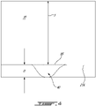
Fig. 4 is a cross-sectional view of a depression defined in a gaspath wall of the stator ofFig. 2 . -
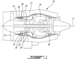
Fig. 1 illustrates an aircraft engine depicted as agas turbine engine 10 of a type preferably provided for use in subsonic flight, generally comprising in serial flow communication afan 12, acompressor section 14 for pressurizing the air, acombustor 16 in which the compressed air is mixed with fuel and ignited for generating an annular stream of hot combustion gases, and aturbine section 18 for extracting energy from the combustion gases. Thefan 12, thecompressor section 14, and theturbine section 18 are rotatable about acentral axis 11 of thegas turbine engine 10. The principles of the present disclosure may apply to any gas turbine engine such as turboprop and turboshaft gas turbine engines. - The
compressor section 14 includes one ormore compressor rotors 22 andstators 24 in fluid communication with therotors 22. The exemplarygas turbine engine 10 ofFig. 1 is a turbofan engine including thefan 12 through which ambient air is propelled. An airflow flowing between blades of thefan 12 is split between anengine core gaspath 15 and abypass flow path 17 downstream of thefan 12. Thegas turbine engine 10 has anengine casing 20 that circumferentially extends around thecentral axis 11. Thecore gaspath 15 is therefore located radially inwardly of theengine casing 20 relative to thecentral axis 11 and thebypass flow path 17 located radially outwardly of theengine casing 20 relative to thecentral axis 11. - As will be described in further detail below, the
compressor section 14 of thegas turbine engine 10 includes at least one compression stage having a tandem stator assembly 30 (which may be alternately referred to as a dual stator assembly), composed of two individual stators, namely afirst stator 31 and asecond stator 32 in immediate flow-wise succession (i.e. without any rotor therebetween); thesecond stator 32 located downstream of thefirst stator 31 relative to the air flow flowing in thecore gaspath 15. In the embodiment depicted inFig. 1 , thetandem stator assembly 30 is shown as being part of the first compression stage, that is it is located downstream of thefan 12 at the inlet of a core of theengine 10 and within theengine core gaspath 15. It is to be understood, however, that the presenttandem stator assembly 30 may form part of other compression stages, such as those further downstream within the core of thegas turbine engine 10, either instead of or addition to being immediately downstream from thefan 12. In some embodiments, thetandem stator assembly 30 may be used in a turbine stage of theturbine section 18. Thetandem stator 30 may be used in thebypass flow path 17. - Referring more particularly to
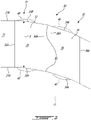
Fig. 2 , a potion of thecompressor section 14 including thetandem stator 30 is shown in greater detail. Thecore gaspath 15 is defined radially between aninner gaspath wall 21A, which may include vane platforms (not shown), and anouter gaspath wall 21B, which may include vane shroud (not shown). Theouter gaspath wall 21B is located radially outwardly of theinner gaspath wall 21A relative to thecentral axis 11. - The
first stator 31 includes a first row of a plurality offirst vanes 33 and thesecond stator 32 includes a second row of a plurality ofsecond vanes 34. Thefirst vanes 33 and thesecond vanes 34 are circumferentially distributed around thecentral axis 11. Thefirst vanes 33 may be staggered relative to thesecond vanes 34. In other words, a circumferential position of each of thefirst vanes 33 may be between circumferential positions of two circumferentially adjacent ones of thesecond vanes 34. Thefirst vanes 33 extend from firstinner ends 33A at theinner gaspath wall 21A to firstouter ends 33B at theouter gaspath wall 21B. Thesecond vanes 34 extend from secondinner ends 34A at theinner gaspath wall 21A to secondouter ends 34B at theouter gaspath wall 21B. - Referring to
Figs. 2-3 , thefirst vanes 33 includefirst airfoils 35 having first leadingedges 35A,first trailing edges 35B downstream of the first leadingedges 35A,first pressure sides 35C (Fig. 3 ), andfirst suction sides 35D (Fig. 3 ) opposed thefirst pressure sides 35C. Thefirst airfoils 35 extend in a direction having a radial component relative to thecentral axis 11 from theinner gaspath wall 21A to theouter gaspath wall 21B. Thesecond vanes 34 includesecond airfoils 36 that extend in a direction having a radial component relative to thecentral axis 11 from theinner gaspath wall 21A to theouter gaspath wall 21B. Thesecond airfoils 36 have second leadingedges 36A, secondtrailing edges 36B downstream of the second leadingedges 36A, second pressure sides, and second suction sides opposed the second pressure sides. - In the embodiment shown, the
first airfoils 35 are offset from thesecond airfoils 36 such that the secondleading edges 36A are located downstream of thefirst trailing edges 35B relative to the air flow flowing in thecore gaspath 15. An axial offset is therefore defined between the secondleading edges 36A and thefirst trailing edges 35B. In some embodiments, thefirst airfoils 35 may be at least partially axially overlapped by thesecond airfoils 36 such that the secondleading edges 36A are located upstream of thefirst trailing edges 35B. In some embodiments, the secondleading edges 36A may be axially aligned with thefirst trailing edges 35B. - In some operating conditions, for instance when the stator (e.g.,
first stator 31,second stator 32, stator 24) is highly loaded, corner loss may occur as a result of boundary layer build up. Large boundary layer build up toward trailing edges of the stator on suction sides may lead to high flow deviation and potential corner separation due to additional pressure side flow leakage across the trailing edge. This may result in flow deviation and wake shedding, which is undesirable. - Still referring to
Figs. 2-3 , thetandem stator 30 includesdepressions 40 that are defined in one or both of theinner gaspath wall 21A and theouter gaspath wall 21B. Thedepressions 40 extend from a baseline surface BS of theinner gaspath wall 21A and/or theouter gaspath wall 21B and away from thecore gaspath 15. The baseline surface BS is a surface of the gaspath walls free of thedepressions 40. As shown inFig. 3 , thedepressions 40 are located circumferentially between thefirst pressure sides 35C and the first suction sides 35D. - Each of the
first airfoils 35 may be axially overlapped by a respective one of thedepressions 40. Similarly, each of thesecond airfoils 36 may be axially overlapped by a respective one of thedepressions 40. Any stator of thecompressor section 14 and/or any stator of theturbine section 18 may include thedepressions 40. Bothstators tandem stator 30 may include thedepressions 40. In some embodiments, only one of the first andsecond stators tandem stator 30 includes thedepressions 40. - Referring more particularly
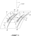
Figs. 3-4 , airfoils of one of the stators are shown in greater detail with theirrespective depressions 40. The description below refer to thefirst stator 31 and to thefirst airfoils 35. It will however be appreciated that the description below may apply to any stators of thegas turbine engine 10. - The
depressions 40 run along the first suction sides 35D of thefirst airfoils 35. Thedepressions 40 may overlap a major portion (e.g., at least 50%) of a chord of thefirst airfoils 35. Thedepressions 40 may be located closer to the first suction sides 35D than to the first pressure sides 35C. A gap may be provided between thedepressions 40 and the first suction sides 35D. A major portion (e.g. 50% or more) of thedepressions 40 may be located upstream of a mid-chord location of thefirst airfoils 35. Thedepressions 40 extend from upstream ends to downstream ends. The upstream ends of thedepressions 40 may be located closer to the firstleading edges 35A than to thefirst trailing edges 35B. The upstream ends of thedepressions 40 may be located upstream of the firstleading edges 35A. - In the illustrated embodiment, a ratio of an axial length h of the
depressions 40 taken along an axial direction relative to thecentral axis 11 to an axial length C of thefirst stator 31 taken along the axial direction from the firstleading edges 35A to thefirst trailing edges 35B ranges from 0.1 to 0.75. A ratio of a thickness t of thedepressions 40 taken along a circumferential direction relative to thecentral axis 11 to a pitch p of thefirst stator 31, which corresponds to a distance extending along the circumferential direction between two adjacent ones of the firstleading edges 35A, may range from 0.05 to 0.5. A ratio of a distance h1 taken along the axial direction relative to thecentral axis 11 from upstream ends of thedepressions 40 to the firstleading edges 35A to the axial length C of thefirst stator 31 taken along the axial direction from the firstleading edges 35A to thefirst trailing edges 35B may range from -0.25 to 0.25. Hence, the upstream ends of thedepressions 40 may be located upstream, downstream, or aligned with the firstleading edges 35A. A ratio of a distance h2 taken along the axial direction relative to thecentral axis 11 from downstream ends of thedepressions 40 to thefirst trailing edge 35B to the axial length C of thefirst stator 31 may range from 0.25 to 0.75. A ratio of a depth D of thedepressions 40 taken along a radial direction relative to thecentral axis 11 to a span S of thefirst airfoils 35 may range from 0.05 to 0.1. The depth D may extend from the baseline surface BS to deepest locations of thedepressions 40. All of the above ratios may apply to any of the stators of the gas turbine engine that include thedepressions 40. - As shown more clearly in
Fig. 3 , the thickness t of the depressions increases along a flow direction of a flow flowing between thefirst airfoils 35. Thedepressions 40 are located adjacent the firstleading edges 35A. Thedepressions 40 may axially overlap the firstleading edges 35A. Thedepressions 40 may be located closer to the first suction sides 35D than to the first pressure sides 35C. Thedepressions 40 may extend substantially parallel to the first suction sides 35D. In the embodiment shown, thedepressions 40 intersect throats T that extend from the firstleading edges 35A of one of thefirst airfoils 35 to thefirst suction side 35D of an adjacent one of thefirst airfoils 35. Thedepressions 40 may be asymmetrical with regards to plane containing thecentral axis 11 and intersecting a center of a space between thefirst vanes 33 and thesecond vanes 34. The depth D of thedepressions 40 may be maximal where they intersect the throats T and may blend smoothly to the inner orouter gaspath walls - The
depressions 40 may be located in vicinity of the leading edge of the stator proximate the suction side. Thedepressions 40 may contribute in lowering the local Mach number near the suction sides. This may help to reduce diffusion on the stator suction side. The decrease in the local Mach number through the throat may help to provide a gentler diffusion compared to a configuration devoid ofsuch depressions 40. This may result in a reduction in the boundary layer buildup at the trailing edges of the stators and may induce smaller wake. Similar benefit may be observed on the pressure side where reduction in diffusion may help to reduce flow blockage. Large corner flow blockage may also be reduced thanks to thedepressions 40 especially when the stator is operated near stall. Thedepressions 40 may contribute in reducing flow losses and may improve overall performance of the compressor and of downstream components. Thedepressions 40 as described herein may contribute in reducing stator corner loss and improve duct loss and entry conditions into downstream components. - The terms "downstream" and "upstream" as used herein are all with reference to a direction of the main airflow through the
core gaspath 15. In the context of the present disclosure, the expression "fluid machine" includes compressors and turbines. - The embodiments described in this document provide non-limiting examples of possible implementations of the present technology. Upon review of the present disclosure, a person of ordinary skill in the art will recognize that changes may be made to the embodiments described herein without departing from the scope of the present technology. Yet further modifications could be implemented by a person of ordinary skill in the art in view of the present disclosure, which modifications would be within the scope of the present technology.
Claims (10)
- A fluid machine for an aircraft engine (10) comprising:a first wall (21A) and a second wall (21B) circumferentially extending around a central axis (11);a gaspath (15) defined between the first wall (21A) and the second wall (21B);a rotor (22) having blades circumferentially distributed around the central axis (11) and extending cross the gaspath (15), the rotor (22) rotatable about the central axis (11); anda stator (31) in fluid communication with the rotor (22) and having:a row of vanes (33) extending across the gaspath and circumferentially distributed around the central axis (11), the vanes (33) having airfoils (35) including leading edges (35A), trailing edges (35B), pressure sides (35C) and suction sides (35D) opposed to the pressure sides (35C); anddepressions (40) defined in the first wall (21A), the depressions (40) extending from a baseline surface (BS) of the first wall (31A) away from the second wall (21B), a depression (40) of the depressions (40) located circumferentially between a pressure side (35C) of the pressure sides (35C) and a suction side (35D) of the suction sides (35D), the depression (40) axially overlapping the airfoils (35) and located closer to the suction side (35D) than to the pressure side (35C), an upstream end of the depression (40) located closer to a leading edge (35A) of the leading edges (35A) than to a trailing edge (35B) of the trailing edges (35B).
- The fluid machine of claim 1, wherein a ratio of an axial length (h) of the depression (40) taken along an axial direction relative to the central axis (11) to an axial length (C) of the stator (31) taken along the axial direction (11) from the leading edges (35A) to the trailing edges (35B) ranges from 0.1 to 0.75.
- The fluid machine of claims 1 or 2, wherein a ratio of a thickness (t) of the depression (40) taken along a circumferential direction relative to the central axis (11) to a pitch (p) of the stator (31) extending along the circumferential direction from the leading edge (35A) of to an adjacent leading edge (35A) of the leading edges (35A) ranges from 0.05 to 0.5.
- The fluid machine of any of claims 1 to 3, wherein a ratio of a distance (h1) taken along an axial direction relative to the central axis (11) from the upstream end of the depression (40) to the leading edge (35A) to an axial length (C) of the stator (31) taken along the axial direction from the leading edges (35A) to the trailing edges (35B) ranges from -0.25 to 0.25.
- The fluid machine of any preceding claim, wherein a ratio of a distance (h2) taken along an axial direction relative to the central axis (11) from a downstream end of the depression (40) to a trailing edge (35B) of the trailing edges (35B) to an axial length (C) of the stator (31) taken along the axial direction from the leading edges (35A) to the trailing edges (35B) ranges from 0.25 to 0.75.
- The fluid machine of any preceding claim, wherein a ratio of a depth (D) of the depression (40) taken along a radial direction relative to the central axis (11) to a span (S) of the airfoils (35) ranges from 0.05 to 0.1.
- The fluid machine of any preceding claim, wherein a thickness (t) of the depression (40) taken along a circumferential direction relative to the central axis (11) increases along a flow direction of a flow (15) flowing between the airfoils (35).
- The fluid machine of any preceding of claim, wherein the depression (40) extends substantially parallel to the suction side (35C).
- The fluid machine of any preceding claim, wherein the depression (40) intersect a throat (T) extending from the leading edge (35A) to an adjacent suction side (35D) of the suction sides (35D).
- An aircraft engine (10) comprising:
a compressor section (14) having a fluid machine as defined in any preceding claim.
Applications Claiming Priority (1)
| Application Number | Priority Date | Filing Date | Title |
|---|---|---|---|
| US17/466,208 US11639666B2 (en) | 2021-09-03 | 2021-09-03 | Stator with depressions in gaspath wall adjacent leading edges |
Publications (1)
| Publication Number | Publication Date |
|---|---|
| EP4144960A1 true EP4144960A1 (en) | 2023-03-08 |
Family
ID=83193252
Family Applications (1)
| Application Number | Title | Priority Date | Filing Date |
|---|---|---|---|
| EP22193989.5A Pending EP4144960A1 (en) | 2021-09-03 | 2022-09-05 | Fluid machine for an aircraft engine and aircraft engine |
Country Status (3)
| Country | Link |
|---|---|
| US (1) | US11639666B2 (en) |
| EP (1) | EP4144960A1 (en) |
| CA (1) | CA3170969A1 (en) |
Citations (13)
| Publication number | Priority date | Publication date | Assignee | Title |
|---|---|---|---|---|
| US20090053066A1 (en) * | 2006-03-16 | 2009-02-26 | Mitsubishi Heavy Industries. Ltd. | Turbine Blade Cascade End Wall |
| US20100196154A1 (en) * | 2008-01-21 | 2010-08-05 | Mitsubishi Heavy Industries, Ltd. | Turbine blade cascade endwall |
| US20100284818A1 (en) * | 2008-02-12 | 2010-11-11 | Mitsubishi Heavy Industries, Ltd. | Turbine blade cascade endwall |
| US20120051894A1 (en) * | 2010-08-31 | 2012-03-01 | General Electric Company | Turbine assembly with end-wall-contoured airfoils and preferenttial clocking |
| US20120051900A1 (en) * | 2010-08-31 | 2012-03-01 | General Electric Company | Turbine nozzle with contoured band |
| US20140169977A1 (en) * | 2012-12-19 | 2014-06-19 | MTU Aero Engines AG | Blade cascade and turbomachine |
| US20140348660A1 (en) * | 2013-05-24 | 2014-11-27 | MTU Aero Engines AG | Blade cascade and continuous-flow machine |
| US20150315916A1 (en) * | 2012-12-28 | 2015-11-05 | United Technologies Corporation | Platform with curved edges |
| US20160115972A1 (en) * | 2014-10-24 | 2016-04-28 | Rolls-Royce Plc | Row of aerofoil members |
| US20170226880A1 (en) * | 2016-02-09 | 2017-08-10 | General Electric Company | Turbine nozzle having non-axisymmetric endwall contour (ewc) and profile |
| US20180223670A1 (en) * | 2017-02-06 | 2018-08-09 | MTU Aero Engines AG | Contouring a blade/vane cascade stage |
| US20180328185A1 (en) * | 2017-05-10 | 2018-11-15 | MTU Aero Engines AG | Contouring of an airfoil array platform |
| US20190120059A1 (en) * | 2017-10-25 | 2019-04-25 | United Technologies Corporation | Geared gas turbine engine |
Family Cites Families (16)
| Publication number | Priority date | Publication date | Assignee | Title |
|---|---|---|---|---|
| US7220100B2 (en) * | 2005-04-14 | 2007-05-22 | General Electric Company | Crescentic ramp turbine stage |
| US8403645B2 (en) * | 2009-09-16 | 2013-03-26 | United Technologies Corporation | Turbofan flow path trenches |
| US8721291B2 (en) * | 2011-07-12 | 2014-05-13 | Siemens Energy, Inc. | Flow directing member for gas turbine engine |
| US9103213B2 (en) * | 2012-02-29 | 2015-08-11 | General Electric Company | Scalloped surface turbine stage with purge trough |
| US9140128B2 (en) * | 2012-09-28 | 2015-09-22 | United Technologes Corporation | Endwall contouring |
| US9638041B2 (en) * | 2013-10-23 | 2017-05-02 | General Electric Company | Turbine bucket having non-axisymmetric base contour |
| DE102014205235A1 (en) | 2014-03-20 | 2015-09-24 | Rolls-Royce Deutschland Ltd & Co Kg | Blade row group |
| DE102014205226A1 (en) | 2014-03-20 | 2015-09-24 | Rolls-Royce Deutschland Ltd & Co Kg | Blade row group |
| US10415392B2 (en) * | 2014-06-18 | 2019-09-17 | Siemens Energy, Inc. | End wall configuration for gas turbine engine |
| US10287901B2 (en) | 2014-12-08 | 2019-05-14 | United Technologies Corporation | Vane assembly of a gas turbine engine |
| US10590781B2 (en) * | 2016-12-21 | 2020-03-17 | General Electric Company | Turbine engine assembly with a component having a leading edge trough |
| EP3404210B1 (en) | 2017-05-15 | 2024-07-31 | MTU Aero Engines AG | Blade cascade segment for a turbomachine with non-axisymmetric platform surface, corresponding blade cascade, blade channel, platform, and turbomachine |
| US11560797B2 (en) * | 2018-03-30 | 2023-01-24 | Siemens Energy Global GmbH & Co. KG | Endwall contouring for a conical endwall |
| JP7250813B2 (en) | 2018-03-30 | 2023-04-03 | シーメンス エナジー グローバル ゲゼルシャフト ミット ベシュレンクテル ハフツング ウント コンパニー コマンディートゲゼルシャフト | Turbine stage platform with endwall profile with corrugated mating surfaces |
| GB201806631D0 (en) * | 2018-04-24 | 2018-06-06 | Rolls Royce Plc | A combustion chamber arrangement and a gas turbine engine comprising a combustion chamber arrangement |
| US11033992B2 (en) | 2018-10-05 | 2021-06-15 | Pratt & Whitney Canada Corp. | Double row compressor stators |
-
2021
- 2021-09-03 US US17/466,208 patent/US11639666B2/en active Active
-
2022
- 2022-08-23 CA CA3170969A patent/CA3170969A1/en active Pending
- 2022-09-05 EP EP22193989.5A patent/EP4144960A1/en active Pending
Patent Citations (13)
| Publication number | Priority date | Publication date | Assignee | Title |
|---|---|---|---|---|
| US20090053066A1 (en) * | 2006-03-16 | 2009-02-26 | Mitsubishi Heavy Industries. Ltd. | Turbine Blade Cascade End Wall |
| US20100196154A1 (en) * | 2008-01-21 | 2010-08-05 | Mitsubishi Heavy Industries, Ltd. | Turbine blade cascade endwall |
| US20100284818A1 (en) * | 2008-02-12 | 2010-11-11 | Mitsubishi Heavy Industries, Ltd. | Turbine blade cascade endwall |
| US20120051894A1 (en) * | 2010-08-31 | 2012-03-01 | General Electric Company | Turbine assembly with end-wall-contoured airfoils and preferenttial clocking |
| US20120051900A1 (en) * | 2010-08-31 | 2012-03-01 | General Electric Company | Turbine nozzle with contoured band |
| US20140169977A1 (en) * | 2012-12-19 | 2014-06-19 | MTU Aero Engines AG | Blade cascade and turbomachine |
| US20150315916A1 (en) * | 2012-12-28 | 2015-11-05 | United Technologies Corporation | Platform with curved edges |
| US20140348660A1 (en) * | 2013-05-24 | 2014-11-27 | MTU Aero Engines AG | Blade cascade and continuous-flow machine |
| US20160115972A1 (en) * | 2014-10-24 | 2016-04-28 | Rolls-Royce Plc | Row of aerofoil members |
| US20170226880A1 (en) * | 2016-02-09 | 2017-08-10 | General Electric Company | Turbine nozzle having non-axisymmetric endwall contour (ewc) and profile |
| US20180223670A1 (en) * | 2017-02-06 | 2018-08-09 | MTU Aero Engines AG | Contouring a blade/vane cascade stage |
| US20180328185A1 (en) * | 2017-05-10 | 2018-11-15 | MTU Aero Engines AG | Contouring of an airfoil array platform |
| US20190120059A1 (en) * | 2017-10-25 | 2019-04-25 | United Technologies Corporation | Geared gas turbine engine |
Also Published As
| Publication number | Publication date |
|---|---|
| US20230072853A1 (en) | 2023-03-09 |
| US11639666B2 (en) | 2023-05-02 |
| CA3170969A1 (en) | 2023-03-03 |
Similar Documents
| Publication | Publication Date | Title |
|---|---|---|
| EP3369891B1 (en) | Gas turbine engine vanes | |
| EP3369893A1 (en) | Gas turbine engine vanes | |
| US12320274B2 (en) | Compressor stator with leading edge fillet | |
| US20190003323A1 (en) | Airfoil assembly with a scalloped flow surface | |
| US11933193B2 (en) | Turbine engine with an airfoil having a set of dimples | |
| US12421853B2 (en) | Turbine engine with reduced cross flow airfoils | |
| EP2728196A2 (en) | Bleed flow passage | |
| CN113389599B (en) | Turbine engine with airfoils for high acceleration and low blade rotation | |
| US20070012046A1 (en) | Gas turbine intermediate structure and a gas turbine engine comprising the intermediate structure | |
| CA2936579A1 (en) | Turbine section with tip flow vanes | |
| EP4520978A1 (en) | Compressor casing with slots and grooves | |
| EP4144960A1 (en) | Fluid machine for an aircraft engine and aircraft engine | |
| US11939880B1 (en) | Airfoil assembly with flow surface | |
| EP4144959A1 (en) | Fluid machine for an aircraft engine and aircraft engine | |
| CN112943383B (en) | Turbine nozzle with airfoils having curved trailing edges | |
| EP2778346B1 (en) | Rotor for a gas turbine engine, corresponding gas turbine engine and method of improving gas turbine engine rotor efficiency | |
| US11415012B1 (en) | Tandem stator with depressions in gaspath wall | |
| US10900414B2 (en) | Fan assembly having flow recirculation circuit with guide vanes | |
| US12196087B2 (en) | Turbine engine with a rotating blade having a fin | |
| US20200165968A1 (en) | Fan assembly having flow recirculation circuit with rotating airfoils |
Legal Events
| Date | Code | Title | Description |
|---|---|---|---|
| PUAI | Public reference made under article 153(3) epc to a published international application that has entered the european phase |
Free format text: ORIGINAL CODE: 0009012 |
|
| STAA | Information on the status of an ep patent application or granted ep patent |
Free format text: STATUS: THE APPLICATION HAS BEEN PUBLISHED |
|
| AK | Designated contracting states |
Kind code of ref document: A1 Designated state(s): AL AT BE BG CH CY CZ DE DK EE ES FI FR GB GR HR HU IE IS IT LI LT LU LV MC MK MT NL NO PL PT RO RS SE SI SK SM TR |
|
| STAA | Information on the status of an ep patent application or granted ep patent |
Free format text: STATUS: REQUEST FOR EXAMINATION WAS MADE |
|
| 17P | Request for examination filed |
Effective date: 20230908 |
|
| RBV | Designated contracting states (corrected) |
Designated state(s): AL AT BE BG CH CY CZ DE DK EE ES FI FR GB GR HR HU IE IS IT LI LT LU LV MC MK MT NL NO PL PT RO RS SE SI SK SM TR |