EP4144648A1 - Heat shield assembly for use with an aircraft engine - Google Patents
Heat shield assembly for use with an aircraft engine Download PDFInfo
- Publication number
- EP4144648A1 EP4144648A1 EP22180057.6A EP22180057A EP4144648A1 EP 4144648 A1 EP4144648 A1 EP 4144648A1 EP 22180057 A EP22180057 A EP 22180057A EP 4144648 A1 EP4144648 A1 EP 4144648A1
- Authority
- EP
- European Patent Office
- Prior art keywords
- heat shield
- shield panel
- slip
- panel
- aircraft
- Prior art date
- Legal status (The legal status is an assumption and is not a legal conclusion. Google has not performed a legal analysis and makes no representation as to the accuracy of the status listed.)
- Granted
Links
Images


Classifications
-
- F—MECHANICAL ENGINEERING; LIGHTING; HEATING; WEAPONS; BLASTING
- F02—COMBUSTION ENGINES; HOT-GAS OR COMBUSTION-PRODUCT ENGINE PLANTS
- F02C—GAS-TURBINE PLANTS; AIR INTAKES FOR JET-PROPULSION PLANTS; CONTROLLING FUEL SUPPLY IN AIR-BREATHING JET-PROPULSION PLANTS
- F02C7/00—Features, components parts, details or accessories, not provided for in, or of interest apart form groups F02C1/00 - F02C6/00; Air intakes for jet-propulsion plants
- F02C7/20—Mounting or supporting of plant; Accommodating heat expansion or creep
-
- B—PERFORMING OPERATIONS; TRANSPORTING
- B64—AIRCRAFT; AVIATION; COSMONAUTICS
- B64D—EQUIPMENT FOR FITTING IN OR TO AIRCRAFT; FLIGHT SUITS; PARACHUTES; ARRANGEMENT OR MOUNTING OF POWER PLANTS OR PROPULSION TRANSMISSIONS IN AIRCRAFT
- B64D27/00—Arrangement or mounting of power plants in aircraft; Aircraft characterised by the type or position of power plants
- B64D27/02—Aircraft characterised by the type or position of power plants
- B64D27/16—Aircraft characterised by the type or position of power plants of jet type
- B64D27/18—Aircraft characterised by the type or position of power plants of jet type within, or attached to, wings
-
- B—PERFORMING OPERATIONS; TRANSPORTING
- B64—AIRCRAFT; AVIATION; COSMONAUTICS
- B64D—EQUIPMENT FOR FITTING IN OR TO AIRCRAFT; FLIGHT SUITS; PARACHUTES; ARRANGEMENT OR MOUNTING OF POWER PLANTS OR PROPULSION TRANSMISSIONS IN AIRCRAFT
- B64D27/00—Arrangement or mounting of power plants in aircraft; Aircraft characterised by the type or position of power plants
- B64D27/40—Arrangements for mounting power plants in aircraft
- B64D27/402—Arrangements for mounting power plants in aircraft comprising box like supporting frames, e.g. pylons or arrangements for embracing the power plant
-
- B—PERFORMING OPERATIONS; TRANSPORTING
- B64—AIRCRAFT; AVIATION; COSMONAUTICS
- B64D—EQUIPMENT FOR FITTING IN OR TO AIRCRAFT; FLIGHT SUITS; PARACHUTES; ARRANGEMENT OR MOUNTING OF POWER PLANTS OR PROPULSION TRANSMISSIONS IN AIRCRAFT
- B64D29/00—Power-plant nacelles, fairings or cowlings
- B64D29/02—Power-plant nacelles, fairings or cowlings associated with wings
-
- B—PERFORMING OPERATIONS; TRANSPORTING
- B64—AIRCRAFT; AVIATION; COSMONAUTICS
- B64D—EQUIPMENT FOR FITTING IN OR TO AIRCRAFT; FLIGHT SUITS; PARACHUTES; ARRANGEMENT OR MOUNTING OF POWER PLANTS OR PROPULSION TRANSMISSIONS IN AIRCRAFT
- B64D29/00—Power-plant nacelles, fairings or cowlings
- B64D29/06—Attaching of nacelles, fairings or cowlings
-
- B—PERFORMING OPERATIONS; TRANSPORTING
- B64—AIRCRAFT; AVIATION; COSMONAUTICS
- B64D—EQUIPMENT FOR FITTING IN OR TO AIRCRAFT; FLIGHT SUITS; PARACHUTES; ARRANGEMENT OR MOUNTING OF POWER PLANTS OR PROPULSION TRANSMISSIONS IN AIRCRAFT
- B64D33/00—Arrangement in aircraft of power plant parts or auxiliaries not otherwise provided for
- B64D33/04—Arrangement in aircraft of power plant parts or auxiliaries not otherwise provided for of exhaust outlets or jet pipes
-
- F—MECHANICAL ENGINEERING; LIGHTING; HEATING; WEAPONS; BLASTING
- F02—COMBUSTION ENGINES; HOT-GAS OR COMBUSTION-PRODUCT ENGINE PLANTS
- F02C—GAS-TURBINE PLANTS; AIR INTAKES FOR JET-PROPULSION PLANTS; CONTROLLING FUEL SUPPLY IN AIR-BREATHING JET-PROPULSION PLANTS
- F02C7/00—Features, components parts, details or accessories, not provided for in, or of interest apart form groups F02C1/00 - F02C6/00; Air intakes for jet-propulsion plants
- F02C7/24—Heat or noise insulation
-
- F—MECHANICAL ENGINEERING; LIGHTING; HEATING; WEAPONS; BLASTING
- F16—ENGINEERING ELEMENTS AND UNITS; GENERAL MEASURES FOR PRODUCING AND MAINTAINING EFFECTIVE FUNCTIONING OF MACHINES OR INSTALLATIONS; THERMAL INSULATION IN GENERAL
- F16B—DEVICES FOR FASTENING OR SECURING CONSTRUCTIONAL ELEMENTS OR MACHINE PARTS TOGETHER, e.g. NAILS, BOLTS, CIRCLIPS, CLAMPS, CLIPS OR WEDGES; JOINTS OR JOINTING
- F16B5/00—Joining sheets or plates, e.g. panels, to one another or to strips or bars parallel to them
- F16B5/02—Joining sheets or plates, e.g. panels, to one another or to strips or bars parallel to them by means of fastening members using screw-thread
- F16B5/0241—Joining sheets or plates, e.g. panels, to one another or to strips or bars parallel to them by means of fastening members using screw-thread with the possibility for the connection to absorb deformation, e.g. thermal or vibrational
-
- F—MECHANICAL ENGINEERING; LIGHTING; HEATING; WEAPONS; BLASTING
- F05—INDEXING SCHEMES RELATING TO ENGINES OR PUMPS IN VARIOUS SUBCLASSES OF CLASSES F01-F04
- F05D—INDEXING SCHEME FOR ASPECTS RELATING TO NON-POSITIVE-DISPLACEMENT MACHINES OR ENGINES, GAS-TURBINES OR JET-PROPULSION PLANTS
- F05D2220/00—Application
- F05D2220/30—Application in turbines
- F05D2220/32—Application in turbines in gas turbines
- F05D2220/323—Application in turbines in gas turbines for aircraft propulsion, e.g. jet engines
-
- F—MECHANICAL ENGINEERING; LIGHTING; HEATING; WEAPONS; BLASTING
- F05—INDEXING SCHEMES RELATING TO ENGINES OR PUMPS IN VARIOUS SUBCLASSES OF CLASSES F01-F04
- F05D—INDEXING SCHEME FOR ASPECTS RELATING TO NON-POSITIVE-DISPLACEMENT MACHINES OR ENGINES, GAS-TURBINES OR JET-PROPULSION PLANTS
- F05D2260/00—Function
- F05D2260/20—Heat transfer, e.g. cooling
- F05D2260/231—Preventing heat transfer
-
- F—MECHANICAL ENGINEERING; LIGHTING; HEATING; WEAPONS; BLASTING
- F16—ENGINEERING ELEMENTS AND UNITS; GENERAL MEASURES FOR PRODUCING AND MAINTAINING EFFECTIVE FUNCTIONING OF MACHINES OR INSTALLATIONS; THERMAL INSULATION IN GENERAL
- F16B—DEVICES FOR FASTENING OR SECURING CONSTRUCTIONAL ELEMENTS OR MACHINE PARTS TOGETHER, e.g. NAILS, BOLTS, CIRCLIPS, CLAMPS, CLIPS OR WEDGES; JOINTS OR JOINTING
- F16B43/00—Washers or equivalent devices; Other devices for supporting bolt-heads or nuts
- F16B43/002—Washers or equivalent devices; Other devices for supporting bolt-heads or nuts with special provisions for reducing friction
Definitions
- the field relates generally to heat shields and, more specifically, to heat shields for aircraft engines that enable thermal expansion and contraction.
- Aircraft engines are typically supported on or coupled to an aircraft structure, such as a wing, with pylons.
- pylons include a support structure that supports the engine, and an aerodynamic fairing extending from the support structure.
- Some fairings are located aft of the engine such that a lower skin panel of the fairing may be exposed to exhaust gas discharged from the engine during operation thereof. Exposure to the exhaust gas use may cause the lower skin panel to undergo thermal expansion and contraction.
- Existing skin panels are generally continuously fastened to the support structure and to other skin panels with rivets. Temperature gradients may be formed across the fairing as the hotter lower skin panel is restrained by comparatively cooler side skin panels of the fairing. Thus, thermal cycling from exposure to the exhaust gas and subsequent cooling can repeatedly cause high stress to the fairing.
- the heat shield assembly includes a structural member, a heat shield panel adapted for exposure to aircraft engine exhaust, an index joint coupling the heat shield panel to the structural member in a fixed positional location, and a plurality of slip joints coupling the heat shield panel to the structural member.
- Each slip joint includes at least one wear buffer coupled to the heat shield panel, and a slip fastener insertable through a slip joint hole in the heat shield panel with a clearance fit.
- a gap defined by the clearance fit is sized to provide a tolerance for expansion and contraction of the heat shield panel relative to the fixed positional location, and the at least one wear buffer is engageable by the slip fastener during expansion and contraction of the heat shield panel.
- the heat shield assembly includes a structural member, a heat shield panel adapted for exposure to aircraft engine exhaust, and a plurality of slip joints coupling the heat shield panel to the structural member.
- Each slip joint includes at least one wear buffer coupled to the heat shield panel, and a slip fastener insertable through a slip joint hole in the heat shield panel with a clearance fit.
- a gap defined by the clearance fit is sized to provide a tolerance for thermal movement of the heat shield panel relative to the structural member, and the at least one wear buffer is engageable by the slip fastener during thermal movement of the heat shield panel.
- the aircraft includes an engine configured to discharge exhaust, a heat shield panel positioned for exposure to aircraft engine exhaust, and a plurality of slip joints coupling the heat shield panel onto the aircraft.
- Each slip joint includes at least one wear buffer coupled to the heat shield panel, and a slip fastener insertable through a slip joint hole in the heat shield panel with a clearance fit.
- a gap defined by the clearance fit is sized to provide a tolerance for thermal movement of the heat shield panel relative to the slip fastener, and the at least one wear buffer is engageable by the slip fastener during thermal movement of the heat shield panel.
- FIG. 1 is a side view of an example aircraft engine support structure 100.
- Support structure 100 includes a wing 102, a pylon 104 extending from wing 102, and an engine 106 is coupled to pylon 104.
- engine 106 discharges primary exhaust 108 and fan exhaust 110 therefrom.
- Primary exhaust 108 is comparatively hotter than fan exhaust 110.
- Pylon 104 includes a heat shield panel 112 and a side skin panel 114 extending from heat shield panel 112.
- Heat shield panel 112 is positioned on an underside of pylon 104, and is positioned aft of engine 106.
- heat shield panel 112 is generally positioned for exposure to primary exhaust 108, and side skin panel 114 is generally positioned for exposure to fan exhaust such that a thermal gradient is formed therebetween.
- heat shield panel 112 is positioned in any location on an aircraft exposed to aircraft engine exhaust.
- FIG. 2 is a schematic of heat shield panel 112.
- Heat shield panel 112 is coupled to side skin panel 114, and also to a substructure 116 of aircraft engine support structure 100.
- Substructure 116 may include any component of aircraft engine support structure 100 that enables the heat shield assembly to function as described herein.
- substructure 116 includes one or more frame members 118 within pylon 104 (shown in FIG. 1 ).
- Frame members 118 extend between wing 102 (shown in FIG. 1 ) and heat shield panel 112, are arranged in a spaced relationship relative to an exhaust flow direction 120, and are oriented generally orthogonally relative to exhaust flow direction 120.
- Substructure 116 may also include side skin panel 114 of pylon 104.
- Heat shield panel 112 may be coupled to substructure 116 with an index joint 122, a plurality of first slip joints 124, and a plurality of second slip joints 126 in a fastening pattern that enables heat shield panel 112 to thermally expand and contract to reduce stress.
- index joint 122 couples heat shield panel 112 to a frame member 118 in a fixed positional location.
- Index joint 122 may include any suitable fastener that limits or eliminates movement of heat shield panel 112 relative to frame member 118.
- index joint 122 is generally centrally located on heat shield panel 112.
- index joint 122 is spaced generally equidistant from opposing side edges 128 of heat shield panel 112 relative to at least a longitudinal axis 130 and a lateral axis 132 of heat shield panel 112. Accordingly, thermal movement 134 of heat shield panel 112 is controlled relative to index joint 122. More specifically, thermal movement 134 of heat shield panel 112 extends generally inward and outward relative to index joint 122.
- First slip joints 124 couple heat shield panel 112 to a respective frame member 118, and second slip joints 126 couple heat shield panel 112 to side skin panel 114 inboard of side edges 128.
- slip joints 124 and 126 provide a tolerance for heat shield panel 112 to expand and contract relative to the fixed positional location of index joint.
- FIGS. 3 and 4 illustrate first slip joint 124.
- First slip joint 124 includes at least one wear buffer 135 coupled to heat shield panel 112.
- the at least one wear buffer 135 includes a first wear pad 136 on a first side 138 of heat shield panel 112, and a second wear pad 140 on a second side 142 of heat shield panel 112 between frame member 118 and heat shield panel 112.
- Wear pads 136 and 140 are coupled to heat shield panel 112, in a fixed position, with fasteners 142 such as rivets.
- the shape of wear pads 136 and 140 is determined by the locations of fasteners 142.
- the locations of fasteners 142 are chosen so that fasteners 142 will not interfere or intersect with frame member 118.
- Each wear pad 136 and 140 has an opening 144 defined therein, and heat shield panel 112 has a slip joint hole 146 defined therein at respective slip joint locations. Each opening 144 is aligned with slip joint hole 146 to enable a slip fastener 148 to be insertable therethrough.
- Slip fastener 148 includes a bolt 150 having a head portion 152 and a body portion 154 extending therefrom.
- body portion 154 couples to frame member 118
- head portion 152 has a wear spacer 156 coupled thereto.
- Wear spacer 156 has an engagement portion 158 and a sleeve portion 160 extending along body portion 154 of bolt 150.
- Body portion 154 and/or sleeve portion 160 are undersized relative to slip joint hole 146 such that slip fastener 148 is insertable therein with a clearance fit.
- a clearance gap 162 defined by the clearance fit provides space for limited movement of slip fastener 148 therein, such as when heat shield panel 112 moves relative to slip fastener 148.
- clearance gap 162 provides a tolerance for expansion and contraction of heat shield panel 112 relative to the fixed positional location.
- engagement portion 158 is sized larger than slip joint hole 146 and openings 144 in wear pads 136 and 140 to enable engagement portion 158 to extend across at least a portion of first wear pad 136, as will be described in more detail below.
- slip fastener 148 secures heat shield panel 112 to frame member 118 in a manner that enables the expansion and contraction to occur.
- a nominal gap 164 may be defined between engagement portion 158 and first wear pad 136 such that a friction fit is defined therebetween.
- First slip joint 124 also includes a wear washer 166 between frame member 118 and second wear pad 140. Accordingly, in operation, engagement portion 158 and wear washer 166 frictionally engage a respective wear pad 136 or 140 as heat shield panel 112 expands and contracts.
- slip fastener 148 is centrally located within slip joint hole 146.
- slip joint hole 146 may be defined within heat shield panel 112 to positionally offset slip fastener 148 therein.
- slip joint hole 146 may be offset at a "cold" position to account for the projected directional thermal movement 134 (i.e., expansion) as shown in FIG. 2 .
- the wear components (e.g., wear buffers 135, slip fastener 148 or one or more parts thereof, and wear washer 166) of first slip joint 124 are fabricated from any material that enables the heat shield assembly to function as described herein.
- the wear material should be wear-resistant at high temperatures (e.g., greater than 1,000°F).
- An example wear material includes, but is not limited to including, a nickel-based alloy material, a chrome carbide material, and a tungsten carbide material.
- Heat shield panel 112 may be fabricated from any suitable material, such as titanium.
- FIGS. 5 and 6 illustrate second slip joint 126.
- first and second wear pads 168 and 170 of second slip joint 126 have any shape that facilitates reducing or eliminating interference between fasteners 142 and side skin panel 114.
- a panel gap 172 between heat shield panel 112 and side skin panel 114 on an outboard side 174 of heat shield panel 112 may not provide sufficient clearance for fasteners 142.
- wear pads 168 and 170 are shaped and oriented to enable fasteners 142 to be positioned on an inboard side 176 of heat shield panel 112 where panel gap 172 is larger as compared to on outboard side 174.
- FIG. 7 is a cross-sectional view of another example slip joint that may be used on heat shield panel 112.
- the at least one wear buffer 135 includes a wear bushing 176 coupled to heat shield panel 112. More specifically wear bushing 176 is undersized relative to slip joint hole 146, and is positioned within slip joint hole 146 with a press fit.
- wear bushing 176 is in a fixed position within slip joint hole 146, and provides sliding contact from a surface thereof that is frictionally engaged by slip fastener 148 as heat shield panel 112 moves relative to frame member 118 and slip fastener 148.
- at least a portion of wear bushing 176 protrudes from heat shield panel 112 to engage slip fastener 148 and/or wear washer 166 in the sliding contact.
- FIG. 8 is a cross-sectional view of another example slip joint that may be used on heat shield panel 112.
- the at least one wear buffer 135 includes a first wear washer 178 on a first side 138 of heat shield panel 112, and a second wear washer 180 on a second side 142 of heat shield panel 112 between frame member 118 and heat shield panel 112.
- Wear washers 178 and 180 are coupled to heat shield panel 112 in a fixed position using any suitable fastening means.
- wear washers 178 and 180 may be mechanically forced or swaged into position within slip joint hole 146.
- wear washers 178 and 180 are forced into slip joint hole 146 to affix wear washers 178 and 180 to heat shield panel 112.
- Wear washers 178 and 180 therefore provide sliding contact from a surface thereof that is frictionally engaged by slip fastener 148 as heat shield panel 112 moves relative to frame member 118 and slip fastener 148.
- the various wear buffers 135 used are coupled to heat shield panel 112 without the use of additional fasteners, thereby reducing the weight of the assembly and reducing aerodynamic drag during flight operations.
- Examples described include an engine fairing heat shield with the lower surface connected to an upper support structure with slip joints.
- the slip joints allow the hotter, lower surface to expand freely about a central location as it is exposed to engine exhaust flow.
- the slip joints are constructed of a nickel material to protect the surrounding structure from damage. In addition, the nickel material has excellent wear resistance even at high operational temperatures.
- the slip joint design is fitted with a clearance tolerance that allows the heat shield panel to move relative to the support structure while minimizing free play "chatter" behavior. Connecting the heat shield panel to the support structure at the fixed central location controls directional expansion and contraction of the heat shield, which enables a reduced tolerance to be provided at each slip joint. Accordingly, the examples described reduce high mechanical loads and stresses caused by exposure of the heat shield panel to the primary engine exhaust flow try.
Landscapes
- Engineering & Computer Science (AREA)
- Chemical & Material Sciences (AREA)
- Combustion & Propulsion (AREA)
- Aviation & Aerospace Engineering (AREA)
- Mechanical Engineering (AREA)
- General Engineering & Computer Science (AREA)
- Connection Of Plates (AREA)
Abstract
Description
- The field relates generally to heat shields and, more specifically, to heat shields for aircraft engines that enable thermal expansion and contraction.
- Aircraft engines are typically supported on or coupled to an aircraft structure, such as a wing, with pylons. At least some known pylons include a support structure that supports the engine, and an aerodynamic fairing extending from the support structure. Some fairings are located aft of the engine such that a lower skin panel of the fairing may be exposed to exhaust gas discharged from the engine during operation thereof. Exposure to the exhaust gas use may cause the lower skin panel to undergo thermal expansion and contraction. Existing skin panels are generally continuously fastened to the support structure and to other skin panels with rivets. Temperature gradients may be formed across the fairing as the hotter lower skin panel is restrained by comparatively cooler side skin panels of the fairing. Thus, thermal cycling from exposure to the exhaust gas and subsequent cooling can repeatedly cause high stress to the fairing.
- This section is intended to introduce the reader to various aspects of art that may be related to various aspects of the disclosure, which are described and/or claimed below. This discussion is believed to be helpful in providing the reader with background information to facilitate a better understanding of the various aspects of the present disclosure. Accordingly, it should be understood that these statements are to be read in this light, and not as admissions of prior art.
- One aspect is a heat shield assembly for use with an aircraft engine. The heat shield assembly includes a structural member, a heat shield panel adapted for exposure to aircraft engine exhaust, an index joint coupling the heat shield panel to the structural member in a fixed positional location, and a plurality of slip joints coupling the heat shield panel to the structural member. Each slip joint includes at least one wear buffer coupled to the heat shield panel, and a slip fastener insertable through a slip joint hole in the heat shield panel with a clearance fit. A gap defined by the clearance fit is sized to provide a tolerance for expansion and contraction of the heat shield panel relative to the fixed positional location, and the at least one wear buffer is engageable by the slip fastener during expansion and contraction of the heat shield panel.
- Another aspect is a heat shield assembly for use with an aircraft engine. The heat shield assembly includes a structural member, a heat shield panel adapted for exposure to aircraft engine exhaust, and a plurality of slip joints coupling the heat shield panel to the structural member. Each slip joint includes at least one wear buffer coupled to the heat shield panel, and a slip fastener insertable through a slip joint hole in the heat shield panel with a clearance fit. A gap defined by the clearance fit is sized to provide a tolerance for thermal movement of the heat shield panel relative to the structural member, and the at least one wear buffer is engageable by the slip fastener during thermal movement of the heat shield panel.
- Yet another aspect is an aircraft. The aircraft includes an engine configured to discharge exhaust, a heat shield panel positioned for exposure to aircraft engine exhaust, and a plurality of slip joints coupling the heat shield panel onto the aircraft. Each slip joint includes at least one wear buffer coupled to the heat shield panel, and a slip fastener insertable through a slip joint hole in the heat shield panel with a clearance fit. A gap defined by the clearance fit is sized to provide a tolerance for thermal movement of the heat shield panel relative to the slip fastener, and the at least one wear buffer is engageable by the slip fastener during thermal movement of the heat shield panel.
- Various refinements exist of the features noted in relation to the above-mentioned aspects of the present disclosure. Further features may also be incorporated in the above-mentioned aspects of the present disclosure as well. These refinements and additional features may exist individually or in any combination. For instance, various features discussed below in relation to any of the illustrated embodiments of the present disclosure may be incorporated into any of the above-described aspects of the present disclosure, alone or in any combination.
-
-
FIG. 1 is a side view illustration of an example aircraft engine support structure. -
FIG. 2 is a schematic illustration of a heat shield panel that may be used in the aircraft engine support structure shown inFIG. 1 . -
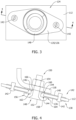
FIG. 3 is an enlarged view of an example slip joint that may be used on the heat shield panel shown inFIG. 2 . -
FIG. 4 is a cross-sectional view of the slip joint shown in FIG. -
FIG. 5 is an enlarged view of another example slip joint that may be used on the heat shield panel shown inFIG. 2 . -
FIG. 6 is a cross-sectional view of the slip joint shown in FIG. -
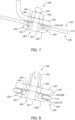
FIG. 7 is a cross-sectional view of another example slip joint that may be used on the heat shield panel shown inFIG. 2 . -
FIG. 8 is a cross-sectional view of another example slip joint that may be used on the heat shield panel shown inFIG. 2 . - Corresponding reference characters indicate corresponding parts throughout the drawings.
-
FIG. 1 is a side view of an example aircraftengine support structure 100.Support structure 100 includes awing 102, apylon 104 extending fromwing 102, and anengine 106 is coupled topylon 104. In operation,engine 106 dischargesprimary exhaust 108 andfan exhaust 110 therefrom.Primary exhaust 108 is comparatively hotter thanfan exhaust 110. Pylon 104 includes aheat shield panel 112 and aside skin panel 114 extending fromheat shield panel 112.Heat shield panel 112 is positioned on an underside ofpylon 104, and is positioned aft ofengine 106. Accordingly,heat shield panel 112 is generally positioned for exposure toprimary exhaust 108, andside skin panel 114 is generally positioned for exposure to fan exhaust such that a thermal gradient is formed therebetween. In an alternative implementation,heat shield panel 112 is positioned in any location on an aircraft exposed to aircraft engine exhaust. -
FIG. 2 is a schematic ofheat shield panel 112.Heat shield panel 112 is coupled toside skin panel 114, and also to a substructure 116 of aircraftengine support structure 100. Substructure 116 may include any component of aircraftengine support structure 100 that enables the heat shield assembly to function as described herein. In the illustrated example, substructure 116 includes one ormore frame members 118 within pylon 104 (shown inFIG. 1 ).Frame members 118 extend between wing 102 (shown inFIG. 1 ) andheat shield panel 112, are arranged in a spaced relationship relative to anexhaust flow direction 120, and are oriented generally orthogonally relative toexhaust flow direction 120. Substructure 116 may also includeside skin panel 114 ofpylon 104. -
Heat shield panel 112 may be coupled to substructure 116 with anindex joint 122, a plurality offirst slip joints 124, and a plurality ofsecond slip joints 126 in a fastening pattern that enablesheat shield panel 112 to thermally expand and contract to reduce stress. For example, index joint 122 couplesheat shield panel 112 to aframe member 118 in a fixed positional location.Index joint 122 may include any suitable fastener that limits or eliminates movement ofheat shield panel 112 relative toframe member 118. In one embodiment,index joint 122 is generally centrally located onheat shield panel 112. In other words,index joint 122 is spaced generally equidistant fromopposing side edges 128 ofheat shield panel 112 relative to at least alongitudinal axis 130 and alateral axis 132 ofheat shield panel 112. Accordingly,thermal movement 134 ofheat shield panel 112 is controlled relative toindex joint 122. More specifically,thermal movement 134 ofheat shield panel 112 extends generally inward and outward relative toindex joint 122. -
First slip joints 124 coupleheat shield panel 112 to arespective frame member 118, andsecond slip joints 126 coupleheat shield panel 112 toside skin panel 114 inboard ofside edges 128. As will be described in more detail below,slip joints heat shield panel 112 to expand and contract relative to the fixed positional location of index joint. -
FIGS. 3 and 4 illustratefirst slip joint 124. First slip joint 124 includes at least one wear buffer 135 coupled toheat shield panel 112. In the illustrated embodiment, the at least one wear buffer 135 includes afirst wear pad 136 on afirst side 138 ofheat shield panel 112, and asecond wear pad 140 on asecond side 142 ofheat shield panel 112 betweenframe member 118 andheat shield panel 112. Wearpads heat shield panel 112, in a fixed position, withfasteners 142 such as rivets. The shape ofwear pads fasteners 142. The locations offasteners 142 are chosen so thatfasteners 142 will not interfere or intersect withframe member 118. Eachwear pad opening 144 defined therein, andheat shield panel 112 has a slipjoint hole 146 defined therein at respective slip joint locations. Eachopening 144 is aligned with slipjoint hole 146 to enable aslip fastener 148 to be insertable therethrough. -
Slip fastener 148 includes abolt 150 having ahead portion 152 and abody portion 154 extending therefrom. In the example embodiment,body portion 154 couples to framemember 118, andhead portion 152 has awear spacer 156 coupled thereto. Wearspacer 156 has anengagement portion 158 and asleeve portion 160 extending alongbody portion 154 ofbolt 150.Body portion 154 and/orsleeve portion 160 are undersized relative to slipjoint hole 146 such thatslip fastener 148 is insertable therein with a clearance fit. Aclearance gap 162 defined by the clearance fit provides space for limited movement ofslip fastener 148 therein, such as whenheat shield panel 112 moves relative to slipfastener 148. Accordingly,clearance gap 162 provides a tolerance for expansion and contraction ofheat shield panel 112 relative to the fixed positional location. In addition,engagement portion 158 is sized larger than slipjoint hole 146 andopenings 144 inwear pads engagement portion 158 to extend across at least a portion offirst wear pad 136, as will be described in more detail below. - In addition,
slip fastener 148 securesheat shield panel 112 to framemember 118 in a manner that enables the expansion and contraction to occur. For example, anominal gap 164 may be defined betweenengagement portion 158 andfirst wear pad 136 such that a friction fit is defined therebetween. First slip joint 124 also includes awear washer 166 betweenframe member 118 andsecond wear pad 140. Accordingly, in operation,engagement portion 158 and wearwasher 166 frictionally engage arespective wear pad heat shield panel 112 expands and contracts. - In the illustrated embodiment,
slip fastener 148 is centrally located within slipjoint hole 146. Alternatively, slipjoint hole 146 may be defined withinheat shield panel 112 to positionally offsetslip fastener 148 therein. For example, slipjoint hole 146 may be offset at a "cold" position to account for the projected directional thermal movement 134 (i.e., expansion) as shown inFIG. 2 . - The wear components (e.g., wear buffers 135,
slip fastener 148 or one or more parts thereof, and wear washer 166) of first slip joint 124 are fabricated from any material that enables the heat shield assembly to function as described herein. The wear material should be wear-resistant at high temperatures (e.g., greater than 1,000°F). An example wear material includes, but is not limited to including, a nickel-based alloy material, a chrome carbide material, and a tungsten carbide material.Heat shield panel 112 may be fabricated from any suitable material, such as titanium. -
FIGS. 5 and 6 illustratesecond slip joint 126. In the illustrated embodiment, first andsecond wear pads fasteners 142 andside skin panel 114. For example, as shown inFIG. 6 , apanel gap 172 betweenheat shield panel 112 andside skin panel 114 on anoutboard side 174 ofheat shield panel 112 may not provide sufficient clearance forfasteners 142. Accordingly, wearpads fasteners 142 to be positioned on aninboard side 176 ofheat shield panel 112 wherepanel gap 172 is larger as compared to onoutboard side 174. -
FIG. 7 is a cross-sectional view of another example slip joint that may be used onheat shield panel 112. In the illustrated embodiment, the at least one wear buffer 135 includes awear bushing 176 coupled toheat shield panel 112. More specifically wearbushing 176 is undersized relative to slipjoint hole 146, and is positioned within slipjoint hole 146 with a press fit. Thus, wearbushing 176 is in a fixed position within slipjoint hole 146, and provides sliding contact from a surface thereof that is frictionally engaged byslip fastener 148 asheat shield panel 112 moves relative to framemember 118 andslip fastener 148. In some embodiments, at least a portion ofwear bushing 176 protrudes fromheat shield panel 112 to engageslip fastener 148 and/or wearwasher 166 in the sliding contact. -
FIG. 8 is a cross-sectional view of another example slip joint that may be used onheat shield panel 112. In the illustrated embodiment, the at least one wear buffer 135 includes a first wear washer 178 on afirst side 138 ofheat shield panel 112, and a second wear washer 180 on asecond side 142 ofheat shield panel 112 betweenframe member 118 andheat shield panel 112. Wear washers 178 and 180 are coupled toheat shield panel 112 in a fixed position using any suitable fastening means. For example, wear washers 178 and 180 may be mechanically forced or swaged into position within slipjoint hole 146. Thus, at least a portion of each wear washer 178 and 180 are forced into slipjoint hole 146 to affix wear washers 178 and 180 toheat shield panel 112. Wear washers 178 and 180 therefore provide sliding contact from a surface thereof that is frictionally engaged byslip fastener 148 asheat shield panel 112 moves relative to framemember 118 andslip fastener 148. - Accordingly, in the embodiments illustrated in
FIGS. 7 and 8 , the various wear buffers 135 used are coupled toheat shield panel 112 without the use of additional fasteners, thereby reducing the weight of the assembly and reducing aerodynamic drag during flight operations. - Examples described include an engine fairing heat shield with the lower surface connected to an upper support structure with slip joints. The slip joints allow the hotter, lower surface to expand freely about a central location as it is exposed to engine exhaust flow. The slip joints are constructed of a nickel material to protect the surrounding structure from damage. In addition, the nickel material has excellent wear resistance even at high operational temperatures. The slip joint design is fitted with a clearance tolerance that allows the heat shield panel to move relative to the support structure while minimizing free play "chatter" behavior. Connecting the heat shield panel to the support structure at the fixed central location controls directional expansion and contraction of the heat shield, which enables a reduced tolerance to be provided at each slip joint. Accordingly, the examples described reduce high mechanical loads and stresses caused by exposure of the heat shield panel to the primary engine exhaust flow try.
- As used herein, an element or step recited in the singular and preceded with the word "a" or "an" should be understood as not excluding plural elements or steps, unless such exclusion is explicitly recited. Furthermore, references to "example", "example implementation" or "one implementation" of the present disclosure are not intended to be interpreted as excluding the existence of additional implementations that also incorporate the recited features.
- Illustrative, non-exclusive examples of inventive subject matter according to the present disclosure are described in the following enumerated paragraphs:
- A1. A heat shield assembly for use with an aircraft engine, the heat shield assembly comprising: a structural member; a heat shield panel adapted for exposure to aircraft engine exhaust; an index joint coupling the heat shield panel to the structural member in a fixed positional location; and a plurality of slip joints coupling the heat shield panel to the structural member, each slip joint comprising: at least one wear buffer coupled to the heat shield panel; and a slip fastener insertable through a slip joint hole in the heat shield panel with a clearance fit, wherein a gap defined by the clearance fit is sized to provide a tolerance for expansion and contraction of the heat shield panel relative to the fixed positional location, and wherein the at least one wear buffer is engageable by the slip fastener during expansion and contraction of the heat shield panel.
- A2. The heat shield assembly of paragraph A1, wherein the index joint is centrally located on the heat shield panel.
- A3. The heat shield assembly of any of paragraphs A1-A2, wherein the at least one wear buffer comprises a wear bushing coupled within the slip joint hole.
- A4. The heat shield assembly of any of paragraphs A1-A3 further comprising a wear washer between the structural member and the wear bushing.
- A5. The heat shield assembly of any of paragraphs A1-A4, wherein the slip fastener is coupled to the at least one wear buffer with a friction fit to enable the expansion and contraction of the heat shield panel.
- A6. The heat shield assembly of any of paragraphs A1-A5, wherein the heat shield panel is formed from titanium.
- A7. A heat shield assembly for use with an aircraft engine, the heat shield assembly comprising: a structural member; a heat shield panel adapted for exposure to aircraft engine exhaust; and a plurality of slip joints coupling the heat shield panel to the structural member, each slip joint comprising: at least one wear buffer coupled to the heat shield panel; and a slip fastener insertable through a slip joint hole in the heat shield panel with a clearance fit, wherein a gap defined by the clearance fit is sized to provide a tolerance for thermal movement of the heat shield panel relative to the structural member, and wherein the at least one wear buffer is engageable by the slip fastener during thermal movement of the heat shield panel.
- A8. The heat shield assembly of paragraph A7 further comprising an index joint coupling the heat shield panel to the structural member in a fixed positional location, wherein the thermal movement is defined by expansion and contraction of the heat shield panel relative to the fixed positional location.
- A9. The heat shield assembly of any of paragraphs A7-A8, wherein the index joint is centrally located on the heat shield panel.
- A10. The heat shield assembly of any of paragraphs A7-A9, wherein the at least one wear buffer comprises a wear bushing coupled within the slip joint hole.
- A11. The heat shield assembly of any of paragraphs A7-A10 further comprising a wear washer between the structural member and the wear bushing.
- A12. The heat shield assembly of any of paragraphs A7-11, wherein the slip fastener is coupled to the at least one wear buffer with a friction fit to enable the thermal movement of the heat shield panel.
- A13. The heat shield assembly of any of paragraphs A7-A12, wherein the heat shield panel is formed from titanium.
- A14. An aircraft comprising: an engine configured to discharge exhaust; a heat shield panel positioned for exposure to aircraft engine exhaust; and a plurality of slip joints coupling the heat shield panel onto the aircraft, wherein each slip joint comprises: at least one wear buffer coupled to the heat shield panel; and a slip fastener insertable through a slip joint hole in the heat shield panel with a clearance fit, wherein a gap defined by the clearance fit is sized to provide a tolerance for thermal movement of the heat shield panel relative to the slip fastener, and wherein the at least one wear buffer is engageable by the slip fastener during thermal movement of the heat shield panel.
- A15. The aircraft of paragraph A14 further comprising a wing and a pylon extending from the wing, wherein the heat shield panel defines a skin panel of an aft fairing section of the pylon.
- A16. The aircraft of any of the paragraphs A14-A15 further comprising a structural member extending from the wing, wherein the structural member and the heat shield panel are coupled together with the slip fastener.
- A17. The aircraft of any of the paragraphs A14-A16, wherein the structural member is one of a frame member extending from the wing, or a side skin panel of the aft fairing section extending from the heat shield panel.
- A18. The aircraft of any of the paragraphs A14-A17 further comprising an index joint coupling the heat shield panel onto the aircraft in a fixed positional location, wherein the thermal movement is defined by expansion and contraction of the heat shield panel relative to the fixed positional location.
- A19. The aircraft of any of the paragraphs A14-A18, wherein the index joint is centrally located on the heat shield panel.
- A20. The aircraft of any of the paragraphs A14-A19, wherein the slip fastener is coupled to the at least one wear buffer with a friction fit to enable the thermal movement of the heat shield panel.
- This written description uses examples to disclose various implementations, including the best mode, and also to enable any person skilled in the art to practice the various implementations, including making and using any devices or systems and performing any incorporated methods. The patentable scope of the disclosure is defined by the claims, and may include other examples that occur to those skilled in the art after reading this specification. Such other examples are intended to be within the scope of the claims if they have structural elements that do not differ from the literal language of the claims, or if they include equivalent structural elements with insubstantial differences from the literal language of the claims.
Claims (15)
- A heat shield assembly for use with an aircraft engine, the heat shield assembly comprising:a structural member (118);a heat shield panel (112) adapted for exposure to aircraft engine exhaust; anda plurality of slip joints (124, 126) coupling the heat shield panel (112) to the structural member (118), each slip joint (124, 126) comprising:
at least one wear buffer (135) coupled to the heat shield panel (112); anda slip fastener (148) insertable through a slip joint hole (146) in the heat shield panel (112) with a clearance fit, wherein a gap defined by the clearance fit is sized to provide a tolerance for thermal movement of the heat shield panel (112) relative to the structural member (118), and wherein the at least one wear buffer (135) is engageable by the slip fastener (148) during thermal movement of the heat shield panel (112). - The heat shield assembly in accordance with Claim 1, further comprising an index joint (122) coupling the heat shield panel (112) to the structural member (118) in a fixed positional location, wherein the thermal movement is defined by expansion and contraction of the heat shield panel (112) relative to the fixed positional location.
- The heat shield assembly in accordance with any of Claims 1-2, wherein the index joint (122) is centrally located on the heat shield panel (112).
- The heat shield assembly in accordance with any of Claims 1-3, wherein the at least one wear buffer (135) comprises a wear bushing (176) coupled within the slip joint hole (146).
- The heat shield assembly in accordance with any of Claims 1-4 further comprising a wear washer (178, 180) between the structural member (118) and the wear bushing (176).
- The heat shield assembly in accordance with any of Claims 1-5, wherein the slip fastener (148) is coupled to the at least one wear buffer (135) with a friction fit to enable the thermal movement of the heat shield panel (112).
- The heat shield assembly in accordance with any of Claims 1-6, wherein the heat shield panel (112) is formed from titanium.
- An aircraft comprising:an engine (106) configured to discharge exhaust;a heat shield panel (112) positioned for exposure to aircraft engine exhaust; anda plurality of slip joints (124, 126) coupling the heat shield panel (112) onto the aircraft, wherein each slip joint (124, 126) comprises:
at least one wear buffer (135) coupled to the heat shield panel (112); anda slip fastener (148) insertable through a slip joint hole (146) in the heat shield panel (112) with a clearance fit, wherein a gap defined by the clearance fit is sized to provide a tolerance for thermal movement of the heat shield panel (112) relative to the slip fastener (148), and wherein the at least one wear buffer (135) is engageable by the slip fastener (148) during thermal movement of the heat shield panel (112). - The aircraft in accordance with Claim 8, further comprising a wing (102) and a pylon (104) extending from the wing (102), wherein the heat shield panel (112) defines a skin panel of an aft fairing section of the pylon (104).
- The aircraft in accordance with any of Claims 8-9, further comprising a structural member (118) extending from the wing, wherein the structural member (118) and the heat shield panel (112) are coupled together with the slip fastener (148).
- The aircraft in accordance with any of Claims 8-10, wherein the structural member (118) is one of a frame member extending from the wing (102), or a side skin panel (114) of the aft fairing section extending from the heat shield panel (112).
- The aircraft in accordance with any of Claims 8-11, further comprising an index joint (122) coupling the heat shield panel (112) onto the aircraft in a fixed positional location, wherein the thermal movement is defined by expansion and contraction of the heat shield panel (112) relative to the fixed positional location.
- The aircraft in accordance with any of Claims 8-12, wherein the index joint (122) is centrally located on the heat shield panel (112).
- The aircraft in accordance with any of Claims 8-13, wherein the slip fastener (148) is coupled to the at least one wear buffer (135) with a friction fit to enable the thermal movement of the heat shield panel (112).
- An aircraft comprising a heat shield assembly according to any of the claims 1-7.
Applications Claiming Priority (1)
| Application Number | Priority Date | Filing Date | Title |
|---|---|---|---|
| US17/465,959 US11781482B2 (en) | 2021-09-03 | 2021-09-03 | Heat shield assembly for use with an aircraft engine |
Publications (2)
| Publication Number | Publication Date |
|---|---|
| EP4144648A1 true EP4144648A1 (en) | 2023-03-08 |
| EP4144648B1 EP4144648B1 (en) | 2025-10-29 |
Family
ID=82163543
Family Applications (1)
| Application Number | Title | Priority Date | Filing Date |
|---|---|---|---|
| EP22180057.6A Active EP4144648B1 (en) | 2021-09-03 | 2022-06-21 | Heat shield assembly for use with an aircraft engine |
Country Status (2)
| Country | Link |
|---|---|
| US (1) | US11781482B2 (en) |
| EP (1) | EP4144648B1 (en) |
Citations (6)
| Publication number | Priority date | Publication date | Assignee | Title |
|---|---|---|---|---|
| US20080178465A1 (en) * | 2007-01-25 | 2008-07-31 | Siemens Power Generation, Inc. | CMC to metal attachment mechanism |
| WO2014135948A2 (en) * | 2013-03-06 | 2014-09-12 | Bombardier Inc. | Aft pylon fairing for aircraft |
| US20180016019A1 (en) * | 2016-07-13 | 2018-01-18 | Rohr, Inc. | Sliding fastener systems to accommodate differential thermal growth |
| EP3275788A1 (en) * | 2016-07-27 | 2018-01-31 | The Boeing Company | Sliding joint kits, systems containing the same, and related methods |
| US20180057140A1 (en) * | 2016-09-01 | 2018-03-01 | The Boeing Company | Heat Shield Flange Sliding Joint |
| US20210078693A1 (en) * | 2019-09-18 | 2021-03-18 | The Boeing Company | Advanced plume suppressing segmented heat shield |
Family Cites Families (17)
| Publication number | Priority date | Publication date | Assignee | Title |
|---|---|---|---|---|
| US4712750A (en) * | 1986-05-02 | 1987-12-15 | The Boeing Company | Temperature control device for jet engine nacelle associated structure |
| US5524846A (en) * | 1993-12-21 | 1996-06-11 | The Boeing Company | Fire protection system for airplanes |
| GB0117550D0 (en) * | 2001-07-19 | 2001-09-12 | Rolls Royce Plc | Joint arrangement |
| US6983912B2 (en) * | 2002-04-30 | 2006-01-10 | The Boeing Company | Hybrid exhaust heat shield for pylon mounted gas turbine engines |
| GB0321056D0 (en) * | 2003-09-09 | 2003-10-08 | Rolls Royce Plc | Joint arrangement |
| US7261489B2 (en) * | 2004-05-20 | 2007-08-28 | United Technologies Corporation | Fastener assembly for attaching a non-metal component to a metal component |
| US20090212184A1 (en) * | 2005-01-20 | 2009-08-27 | Hensley Kim & Edgington, LLC | Articulated Mounting Systems And Bearings For Joints Thereof |
| FR2901243B1 (en) * | 2006-05-16 | 2008-06-27 | Airbus France Sas | DEVICE FOR HITCHING AN AIRCRAFT ENGINE |
| FR2913665B1 (en) * | 2007-03-16 | 2009-06-05 | Airbus France Sa | LOWER REAR AERODYNAMIC FAIRING FOR AN AIRCRAFT ENGINE CLAMPING DEVICE |
| FR2921342B1 (en) * | 2007-09-20 | 2010-03-12 | Airbus France | LOWER REAR AERODYNAMIC FAIRING FOR AN AIRCRAFT ENGINE CLAMPING DEVICE |
| US7943227B2 (en) * | 2007-10-11 | 2011-05-17 | The Boeing Company | Ceramic heat shield |
| FR2981636B1 (en) * | 2011-10-19 | 2013-12-27 | Airbus Operations Sas | AERODYNAMIC REAR FITTING FOR AN AIRCRAFT ENGINE HANDLING DEVICE, COMPRISING A THERMAL SHIELD CAPABLE OF FREE DILATION |
| FR3013678B1 (en) * | 2013-11-25 | 2015-11-20 | Airbus Operations Sas | AERODYNAMIC CARENAGE |
| EP3048271B1 (en) * | 2014-12-10 | 2020-05-27 | Rolls-Royce Corporation | Stiffening rib |
| CN109715928B (en) * | 2016-05-30 | 2021-06-25 | 加拿大空客有限合伙公司 | aircraft engine components |
| CA3048823C (en) * | 2019-07-08 | 2023-10-03 | Mike Richard John Smith | Gas-wind turbine engine |
| US12025635B2 (en) * | 2021-01-08 | 2024-07-02 | CPP Incorporated | Calibratable pedestrian pressure probe with self-aligning collar |
-
2021
- 2021-09-03 US US17/465,959 patent/US11781482B2/en active Active
-
2022
- 2022-06-21 EP EP22180057.6A patent/EP4144648B1/en active Active
Patent Citations (6)
| Publication number | Priority date | Publication date | Assignee | Title |
|---|---|---|---|---|
| US20080178465A1 (en) * | 2007-01-25 | 2008-07-31 | Siemens Power Generation, Inc. | CMC to metal attachment mechanism |
| WO2014135948A2 (en) * | 2013-03-06 | 2014-09-12 | Bombardier Inc. | Aft pylon fairing for aircraft |
| US20180016019A1 (en) * | 2016-07-13 | 2018-01-18 | Rohr, Inc. | Sliding fastener systems to accommodate differential thermal growth |
| EP3275788A1 (en) * | 2016-07-27 | 2018-01-31 | The Boeing Company | Sliding joint kits, systems containing the same, and related methods |
| US20180057140A1 (en) * | 2016-09-01 | 2018-03-01 | The Boeing Company | Heat Shield Flange Sliding Joint |
| US20210078693A1 (en) * | 2019-09-18 | 2021-03-18 | The Boeing Company | Advanced plume suppressing segmented heat shield |
Also Published As
| Publication number | Publication date |
|---|---|
| US11781482B2 (en) | 2023-10-10 |
| EP4144648B1 (en) | 2025-10-29 |
| US20230071244A1 (en) | 2023-03-09 |
Similar Documents
| Publication | Publication Date | Title |
|---|---|---|
| US8844862B2 (en) | Aft pylon fairing for aircraft engine suspension system, comprising a heat shield capable of expanding freely | |
| EP1375348B1 (en) | Aircraft engine mount with single thrust link | |
| US5451116A (en) | Tripod plate for turbine flowpath | |
| US7153054B2 (en) | Fastener assembly for attaching a non-metal component to a metal component | |
| US20110155847A1 (en) | Aft pylon fairing for an aircraft engine suspension system | |
| US11536454B2 (en) | Combustor wall assembly for gas turbine engine | |
| EP1923578A2 (en) | CMC fastening system | |
| CN107380460B (en) | Engine assemblies and aircraft for use in aircraft | |
| US11286798B2 (en) | Airfoil assembly with ceramic matrix composite parts and load-transfer features | |
| CA2815123A1 (en) | Anti-rotation shroud for turbine engines | |
| EP0623742B1 (en) | Nozzle seal assembly for a gas turbine engine exhaust nozzle | |
| US8955796B2 (en) | Aft aerodynamic fairing with improved thermal resistance for a pylon for attaching an aircraft propelling assembly | |
| US8925332B2 (en) | Anti-fire seal assembly and nacelle comprising such a seal | |
| EP3187693A1 (en) | Wear resistant frame liner joint assembly for a gas turbine engine | |
| EP3290329B1 (en) | Thermal expansion joint | |
| CN117167101B (en) | Turbine outer ring connection structure and turbine engine | |
| US11781482B2 (en) | Heat shield assembly for use with an aircraft engine | |
| US9783285B2 (en) | Thermal insulation support | |
| EP2096292B1 (en) | Exhaust nozzle seal with segmented basesheet disposed between side rails | |
| US11945567B2 (en) | Fitting for a stiffened panel | |
| US11149560B2 (en) | Airfoil assembly with ceramic matrix composite parts and load-transfer features | |
| US6202405B1 (en) | Wall construction for a combustion chamber or a nozzle of a high performance propulsion plant | |
| US5103638A (en) | Mounting arrangement | |
| US9604727B2 (en) | Aerodynamic fairing | |
| US20210078692A1 (en) | Heat shield for an aircraft |
Legal Events
| Date | Code | Title | Description |
|---|---|---|---|
| PUAI | Public reference made under article 153(3) epc to a published international application that has entered the european phase |
Free format text: ORIGINAL CODE: 0009012 |
|
| STAA | Information on the status of an ep patent application or granted ep patent |
Free format text: STATUS: THE APPLICATION HAS BEEN PUBLISHED |
|
| AK | Designated contracting states |
Kind code of ref document: A1 Designated state(s): AL AT BE BG CH CY CZ DE DK EE ES FI FR GB GR HR HU IE IS IT LI LT LU LV MC MK MT NL NO PL PT RO RS SE SI SK SM TR |
|
| RAP3 | Party data changed (applicant data changed or rights of an application transferred) |
Owner name: THE BOEING COMPANY |
|
| STAA | Information on the status of an ep patent application or granted ep patent |
Free format text: STATUS: REQUEST FOR EXAMINATION WAS MADE |
|
| 17P | Request for examination filed |
Effective date: 20230907 |
|
| RBV | Designated contracting states (corrected) |
Designated state(s): AL AT BE BG CH CY CZ DE DK EE ES FI FR GB GR HR HU IE IS IT LI LT LU LV MC MK MT NL NO PL PT RO RS SE SI SK SM TR |
|
| STAA | Information on the status of an ep patent application or granted ep patent |
Free format text: STATUS: EXAMINATION IS IN PROGRESS |
|
| 17Q | First examination report despatched |
Effective date: 20240625 |
|
| GRAP | Despatch of communication of intention to grant a patent |
Free format text: ORIGINAL CODE: EPIDOSNIGR1 |
|
| STAA | Information on the status of an ep patent application or granted ep patent |
Free format text: STATUS: GRANT OF PATENT IS INTENDED |
|
| RIC1 | Information provided on ipc code assigned before grant |
Ipc: F16B 43/00 20060101ALN20250512BHEP Ipc: F16B 5/04 20060101ALN20250512BHEP Ipc: B64D 27/40 20240101ALI20250512BHEP Ipc: F16B 5/02 20060101ALI20250512BHEP Ipc: B64D 29/02 20060101ALI20250512BHEP Ipc: B64D 29/06 20060101AFI20250512BHEP |
|
| INTG | Intention to grant announced |
Effective date: 20250527 |
|
| GRAS | Grant fee paid |
Free format text: ORIGINAL CODE: EPIDOSNIGR3 |
|
| GRAA | (expected) grant |
Free format text: ORIGINAL CODE: 0009210 |
|
| STAA | Information on the status of an ep patent application or granted ep patent |
Free format text: STATUS: THE PATENT HAS BEEN GRANTED |
|
| P01 | Opt-out of the competence of the unified patent court (upc) registered |
Free format text: CASE NUMBER: UPC_APP_5412_4144648/2025 Effective date: 20250829 |
|
| AK | Designated contracting states |
Kind code of ref document: B1 Designated state(s): AL AT BE BG CH CY CZ DE DK EE ES FI FR GB GR HR HU IE IS IT LI LT LU LV MC MK MT NL NO PL PT RO RS SE SI SK SM TR |
|
| REG | Reference to a national code |
Ref country code: CH Ref legal event code: F10 Free format text: ST27 STATUS EVENT CODE: U-0-0-F10-F00 (AS PROVIDED BY THE NATIONAL OFFICE) Effective date: 20251029 Ref country code: GB Ref legal event code: FG4D |
|
| REG | Reference to a national code |
Ref country code: IE Ref legal event code: FG4D |
|
| REG | Reference to a national code |
Ref country code: DE Ref legal event code: R096 Ref document number: 602022023775 Country of ref document: DE |
|
| REG | Reference to a national code |
Ref country code: NL Ref legal event code: MP Effective date: 20251029 |
|
| PG25 | Lapsed in a contracting state [announced via postgrant information from national office to epo] |
Ref country code: ES Free format text: LAPSE BECAUSE OF FAILURE TO SUBMIT A TRANSLATION OF THE DESCRIPTION OR TO PAY THE FEE WITHIN THE PRESCRIBED TIME-LIMIT Effective date: 20251029 |
|
| REG | Reference to a national code |
Ref country code: LT Ref legal event code: MG9D |
|
| PG25 | Lapsed in a contracting state [announced via postgrant information from national office to epo] |
Ref country code: NO Free format text: LAPSE BECAUSE OF FAILURE TO SUBMIT A TRANSLATION OF THE DESCRIPTION OR TO PAY THE FEE WITHIN THE PRESCRIBED TIME-LIMIT Effective date: 20260129 |
|
| PG25 | Lapsed in a contracting state [announced via postgrant information from national office to epo] |
Ref country code: HR Free format text: LAPSE BECAUSE OF FAILURE TO SUBMIT A TRANSLATION OF THE DESCRIPTION OR TO PAY THE FEE WITHIN THE PRESCRIBED TIME-LIMIT Effective date: 20251029 Ref country code: AT Free format text: LAPSE BECAUSE OF FAILURE TO SUBMIT A TRANSLATION OF THE DESCRIPTION OR TO PAY THE FEE WITHIN THE PRESCRIBED TIME-LIMIT Effective date: 20251029 Ref country code: FI Free format text: LAPSE BECAUSE OF FAILURE TO SUBMIT A TRANSLATION OF THE DESCRIPTION OR TO PAY THE FEE WITHIN THE PRESCRIBED TIME-LIMIT Effective date: 20251029 |
|
| REG | Reference to a national code |
Ref country code: AT Ref legal event code: MK05 Ref document number: 1851333 Country of ref document: AT Kind code of ref document: T Effective date: 20251029 |
|
| PG25 | Lapsed in a contracting state [announced via postgrant information from national office to epo] |
Ref country code: NL Free format text: LAPSE BECAUSE OF FAILURE TO SUBMIT A TRANSLATION OF THE DESCRIPTION OR TO PAY THE FEE WITHIN THE PRESCRIBED TIME-LIMIT Effective date: 20251029 |
|
| PG25 | Lapsed in a contracting state [announced via postgrant information from national office to epo] |
Ref country code: RS Free format text: LAPSE BECAUSE OF FAILURE TO SUBMIT A TRANSLATION OF THE DESCRIPTION OR TO PAY THE FEE WITHIN THE PRESCRIBED TIME-LIMIT Effective date: 20260129 |
|
| PG25 | Lapsed in a contracting state [announced via postgrant information from national office to epo] |
Ref country code: IS Free format text: LAPSE BECAUSE OF FAILURE TO SUBMIT A TRANSLATION OF THE DESCRIPTION OR TO PAY THE FEE WITHIN THE PRESCRIBED TIME-LIMIT Effective date: 20260228 |
|
| PG25 | Lapsed in a contracting state [announced via postgrant information from national office to epo] |
Ref country code: PT Free format text: LAPSE BECAUSE OF FAILURE TO SUBMIT A TRANSLATION OF THE DESCRIPTION OR TO PAY THE FEE WITHIN THE PRESCRIBED TIME-LIMIT Effective date: 20260302 |
|
| PG25 | Lapsed in a contracting state [announced via postgrant information from national office to epo] |
Ref country code: PL Free format text: LAPSE BECAUSE OF FAILURE TO SUBMIT A TRANSLATION OF THE DESCRIPTION OR TO PAY THE FEE WITHIN THE PRESCRIBED TIME-LIMIT Effective date: 20251029 |
|
| PG25 | Lapsed in a contracting state [announced via postgrant information from national office to epo] |
Ref country code: LV Free format text: LAPSE BECAUSE OF FAILURE TO SUBMIT A TRANSLATION OF THE DESCRIPTION OR TO PAY THE FEE WITHIN THE PRESCRIBED TIME-LIMIT Effective date: 20251029 |
|
| PG25 | Lapsed in a contracting state [announced via postgrant information from national office to epo] |
Ref country code: BG Free format text: LAPSE BECAUSE OF FAILURE TO SUBMIT A TRANSLATION OF THE DESCRIPTION OR TO PAY THE FEE WITHIN THE PRESCRIBED TIME-LIMIT Effective date: 20251029 |
|
| PG25 | Lapsed in a contracting state [announced via postgrant information from national office to epo] |
Ref country code: LT Free format text: LAPSE BECAUSE OF FAILURE TO SUBMIT A TRANSLATION OF THE DESCRIPTION OR TO PAY THE FEE WITHIN THE PRESCRIBED TIME-LIMIT Effective date: 20251029 |
|
| PG25 | Lapsed in a contracting state [announced via postgrant information from national office to epo] |
Ref country code: SM Free format text: LAPSE BECAUSE OF FAILURE TO SUBMIT A TRANSLATION OF THE DESCRIPTION OR TO PAY THE FEE WITHIN THE PRESCRIBED TIME-LIMIT Effective date: 20251029 |
|
| PG25 | Lapsed in a contracting state [announced via postgrant information from national office to epo] |
Ref country code: DK Free format text: LAPSE BECAUSE OF FAILURE TO SUBMIT A TRANSLATION OF THE DESCRIPTION OR TO PAY THE FEE WITHIN THE PRESCRIBED TIME-LIMIT Effective date: 20251029 |
|
| PGFP | Annual fee paid to national office [announced via postgrant information from national office to epo] |
Ref country code: GB Payment date: 20260629 Year of fee payment: 5 |
|
| PG25 | Lapsed in a contracting state [announced via postgrant information from national office to epo] |
Ref country code: IT Free format text: LAPSE BECAUSE OF FAILURE TO SUBMIT A TRANSLATION OF THE DESCRIPTION OR TO PAY THE FEE WITHIN THE PRESCRIBED TIME-LIMIT Effective date: 20251029 |
|
| PGFP | Annual fee paid to national office [announced via postgrant information from national office to epo] |
Ref country code: DE Payment date: 20260629 Year of fee payment: 5 |
|
| PG25 | Lapsed in a contracting state [announced via postgrant information from national office to epo] |
Ref country code: EE Free format text: LAPSE BECAUSE OF FAILURE TO SUBMIT A TRANSLATION OF THE DESCRIPTION OR TO PAY THE FEE WITHIN THE PRESCRIBED TIME-LIMIT Effective date: 20251029 |
|
| PG25 | Lapsed in a contracting state [announced via postgrant information from national office to epo] |
Ref country code: CZ Free format text: LAPSE BECAUSE OF FAILURE TO SUBMIT A TRANSLATION OF THE DESCRIPTION OR TO PAY THE FEE WITHIN THE PRESCRIBED TIME-LIMIT Effective date: 20251029 |
|
| PGFP | Annual fee paid to national office [announced via postgrant information from national office to epo] |
Ref country code: FR Payment date: 20260625 Year of fee payment: 5 |
|
| PG25 | Lapsed in a contracting state [announced via postgrant information from national office to epo] |
Ref country code: SK Free format text: LAPSE BECAUSE OF FAILURE TO SUBMIT A TRANSLATION OF THE DESCRIPTION OR TO PAY THE FEE WITHIN THE PRESCRIBED TIME-LIMIT Effective date: 20251029 |
|
| PG25 | Lapsed in a contracting state [announced via postgrant information from national office to epo] |
Ref country code: SE Free format text: LAPSE BECAUSE OF FAILURE TO SUBMIT A TRANSLATION OF THE DESCRIPTION OR TO PAY THE FEE WITHIN THE PRESCRIBED TIME-LIMIT Effective date: 20251029 |