EP4144609A1 - Antivibration support structure for vehicle-mounted instrument, and vehicle-mounted instrument - Google Patents
Antivibration support structure for vehicle-mounted instrument, and vehicle-mounted instrument Download PDFInfo
- Publication number
- EP4144609A1 EP4144609A1 EP20933307.9A EP20933307A EP4144609A1 EP 4144609 A1 EP4144609 A1 EP 4144609A1 EP 20933307 A EP20933307 A EP 20933307A EP 4144609 A1 EP4144609 A1 EP 4144609A1
- Authority
- EP
- European Patent Office
- Prior art keywords
- support
- elastic member
- vehicle
- onboard device
- target
- Prior art date
- Legal status (The legal status is an assumption and is not a legal conclusion. Google has not performed a legal analysis and makes no representation as to the accuracy of the status listed.)
- Granted
Links
Images

Classifications
-
- B—PERFORMING OPERATIONS; TRANSPORTING
- B61—RAILWAYS
- B61C—LOCOMOTIVES; MOTOR RAILCARS
- B61C17/00—Arrangement or disposition of parts; Details or accessories not otherwise provided for; Use of control gear and control systems
-
- F—MECHANICAL ENGINEERING; LIGHTING; HEATING; WEAPONS; BLASTING
- F16—ENGINEERING ELEMENTS AND UNITS; GENERAL MEASURES FOR PRODUCING AND MAINTAINING EFFECTIVE FUNCTIONING OF MACHINES OR INSTALLATIONS; THERMAL INSULATION IN GENERAL
- F16F—SPRINGS; SHOCK-ABSORBERS; MEANS FOR DAMPING VIBRATION
- F16F15/00—Suppression of vibrations in systems; Means or arrangements for avoiding or reducing out-of-balance forces, e.g. due to motion
- F16F15/02—Suppression of vibrations of non-rotating, e.g. reciprocating systems; Suppression of vibrations of rotating systems by use of members not moving with the rotating systems
- F16F15/04—Suppression of vibrations of non-rotating, e.g. reciprocating systems; Suppression of vibrations of rotating systems by use of members not moving with the rotating systems using elastic means
- F16F15/08—Suppression of vibrations of non-rotating, e.g. reciprocating systems; Suppression of vibrations of rotating systems by use of members not moving with the rotating systems using elastic means with rubber springs ; with springs made of rubber and metal
Definitions
- the present disclosure relates to an anti-vibration support structure for an onboard device and an onboard device.
- the anti-vibration support structure for an onboard device disclosed in PTL 1 is an anti-vibration support structure for an onboard device of a railroad vehicle, and in this structure, an underfloor device is suspended from and held by a floor structure of the railroad vehicle. In this structure, anti-vibration rubber is used to hold the underfloor device.
- This structure fixes the underfloor device to the floor structure via suspension bolts. The underfloor device is supported by the suspension bolts. Suspension positions at which the suspension bolts are suspended are placed such that a suspension point load is uniformly applied to the suspension bolts.
- the anti-vibration support structure for an onboard device may include an elastic member such as anti-vibration rubber.
- an elastic member such as anti-vibration rubber.
- a conventional anti-vibration support structure for an onboard device which includes the elastic member such as anti-vibration rubber may require a plurality of suspension bolts or require adjustment of a suspension point load.
- the conventional anti-vibration support structure for an onboard device has a complicated structure and is assembled in a complicated manner.
- An object of the present disclosure is to provide an anti-vibration support structure for an onboard device that can be simplified in terms of structure and assembly.
- An anti-vibration support structure for an onboard device is for a vehicle to support an onboard device placed under a floor of the vehicle.
- the anti-vibration support structure for an onboard device includes a first support, a second support, a target support, a first elastic member, and a second elastic member.
- the first support is located under the floor of the vehicle and is fixed to the vehicle.
- the first support extends at least in part horizontally.
- the second support is located under the floor of the vehicle and is fixed to the vehicle.
- the second support is located above the first support while being apart from the first support.
- the target support is fixed to the onboard device.
- the target support is located at least in part between the first support and the second support so as not to be in contact with the first support and the second support.
- the first elastic member is located between the first support and the target support.
- the second elastic member is located between the second support and the target support.
- the target support is supported by being retained between the first support and the second support at least via the
- the target support is supported by the support via the elastic member without necessarily using a fastening member such as a bolt.
- the anti-vibration support structure for an onboard device can have anti-vibration performance owing to the elastic member and be simplified in terms of structure and assembly.
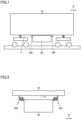
- Fig. 1 is a schematic side view of a vehicle and an onboard device supported by an anti-vibration support structure for an onboard device.
- Fig. 2 is a schematic side view of the anti-vibration support structure for an onboard device according to the embodiment.
- Fig. 3 is an enlarged side view of a configuration of the anti-vibration support structure for an onboard device according to the embodiment.
- Fig. 4 is a plan view showing a configuration of the onboard device according to the embodiment. In Fig. 4 , a vehicle is not shown.
- an anti-vibration support structure for an onboard device 100 is for a vehicle 10 to support an onboard device 20 placed under the floor of the vehicle.
- vehicle 10 is a railroad vehicle.
- Vehicle 10 has a floor structure 11.
- under the floor of vehicle 10 refers to "under floor structure 11".
- Floor structure 11 forms at least part of the floor surface of a passenger compartment of vehicle 10.
- onboard device 20 is specifically an on-board transformer in the present embodiment.
- Onboard device 20 causes mechanical vibrations.
- the mechanical vibrations may make the passenger in the passenger compartment uncomfortable as such mechanical vibrations propagate directly to floor structure 11.
- sound waves generated by the mechanical vibrations of onboard device 20 may make the passenger uncomfortable as the sound waves propagate to the passenger in the passenger compartment via floor structure 11.
- anti-vibration support structure for an onboard device 100 preferably reduces the propagation of such vibrations to vehicle 10 as much as possible.
- anti-vibration support structure for an onboard device 100 includes a first support 110, a second support 120, a target support 130, a first elastic member 140, a second elastic member 150, and a spacer 160.
- Anti-vibration support structure for an onboard device 100 further includes a support body 105 located under the floor of vehicle 10.
- Support body 105 is connected directly to vehicle 10.
- support body 105 is connected directly to floor structure 11 of vehicle 10.
- Support body 105 extends vertically.
- First support 110 is located under the floor of vehicle 10 and is fixed to vehicle 10. First support 110 extends at least in part horizontally. In the present embodiment, the entire first support 110 extends horizontally. First support 110 extends from support body 105 to one side in a travel direction D of vehicle 10. In other words, first support 110 is connected and fixed to vehicle 10 via support body 105. First support 110 may extend from support body 105 in a direction crossing travel direction D of vehicle 10.
- Second support 120 is located under the floor of vehicle 10 and is fixed to vehicle 10. Second support 120 is located above first support 110 while being apart from first support 110. In the present embodiment, second support 120 extends horizontally. Second support 120 extends along first support 110 from support body 105 to one side in travel direction D of vehicle 10. In other words, second support 120 is connected and fixed to vehicle 10 via support body 105. Second support 120 may be connected and fixed to vehicle 10 via a member different from support body 105.
- each of first support 110 and second support 120 extends uniformly in the direction perpendicular to the direction of extension of first support 110 (in the present embodiment, travel direction D of vehicle 10), as viewed vertically.
- the material for each of support body 105, first support 110, and second support 120 is not particularly limited, it may be, for example, stainless steel or aluminum alloy.
- target support 130 is fixed to onboard device 20.
- Target support 130 is located at least in part between first support 110 and second support 120 so as not to be in contact with first support 110 and second support 120.
- target support 130 extends horizontally.
- Target support 130 is located above onboard device 20.
- Anti-vibration support structure for an onboard device 100 further includes a suspension 135.
- Suspension 135 extends downward from a portion of target support 130 which is not located between first support 110 and second support 120.
- Suspension 135 is connected to a side surface of onboard device 20 on the side opposite to the first support 110 side, as viewed vertically.
- Suspension 135 is connected to the side surface of onboard device 20 by, for example, welding.
- target support 130 is connected and fixed to onboard device 20 via suspension 135.
- target support 130 extends uniformly in the direction perpendicular to the direction of extension of first support 110 (in the present embodiment, travel direction D of vehicle 10), as viewed vertically.
- Anti-vibration support structure for an onboard device 100 may also include a plurality of target supports 130 as target support 130, and when anti-vibration support structure for an onboard device 100 includes a plurality of target supports 130, target supports 130 are placed adjacent to each other in the direction perpendicular to the direction of extension of first support 110 (in the present embodiment, travel direction D of vehicle 10).
- the material for each of target support 130 and suspension 135 is not particularly limited, it may be stainless steel or coated steel.
- first elastic member 140 is located between first support 110 and target support 130.
- first elastic member 140 has an outer shape of a flat board extending horizontally.
- First elastic member 140 may be located as a plurality of first elastic members 140 between first support 110 and target support 130. In this case, first elastic members 140 may be placed, for example, adjacent to each other horizontally.
- first elastic member 140 is vertically in direct contact with target support 130.
- First elastic member 140 may be vertically adjacent to target support 130 via a spacer similar to spacer 160, which will be described below.
- first elastic member 140 is not vertically in direct contact with first support 110 in the present embodiment, first elastic member 140 may be vertically in direct contact with first support 110.
- Second elastic member 150 is located between second support 120 and target support 130.
- second elastic member 150 has an outer shape of a flat board extending horizontally.
- Second elastic member 150 may be located as a plurality of second elastic members 150 between second support 120 and target support 130. In this case, second elastic members 150 may be placed adjacent to each other horizontally.
- second elastic member 150 is vertically in direct contact with target support 130. In the present embodiment, second elastic member 150 is vertically adjacent to second support 120. Second elastic member 150 may be vertically adjacent to target support 130 or adjacent to second support 120 via a spacer similar to spacer 160 described below.
- First elastic member 140 and second elastic member 150 are each made of a rubber composite.
- a rubber component included in the rubber composite is not particularly limited.
- the rubber composite may include, for example, natural rubber, styrene-butadiene rubber, isoprene rubber, butadiene rubber, nitrile rubber, butyl rubber, or the like.
- First elastic member 140 made of the rubber composite is not bonded by vulcanization to each of target support 130, second elastic member 150, and spacer 160, and second elastic member 150 made of the rubber composite is not bonded by vulcanization to each of target support 130, first elastic member 140, and spacer 160.
- Spacer 160 is retained between first support 110 and second support 120 together with target support 130, first elastic member 140, and second elastic member 150.
- spacer 160 is vertically located between first support 110 and first elastic member 140 and is adjacent to each of first support 110 and first elastic member 140.
- Spacer 160 may be located at a position different from the above-mentioned position between first support 110 and second support 120.
- spacer 160 may be vertically located between target support 130 and first elastic member 140 and be adjacent to each of target support 130 and first elastic member 140.
- Spacer 160 may be vertically located between target support 130 and second elastic member 150 and be adjacent to each of target support 130 and second elastic member 150.
- Spacer 160 may be vertically located between second elastic member 150 and second support 120 and be adjacent to each of second elastic member 150 and second support 120.
- spacer 160 is not particularly limited, it may be, for example, stainless steel.
- target support 130 is retained between first support 110 and second support 120 at least via first elastic member 140 and second elastic member 150, and accordingly, is supported without a fastening member such as a bolt.
- anti-vibration support structure for an onboard device 100 also includes a support body 205, a first support 210, a second support 220, a target support 230, a suspension 235, a first elastic member 240, a second elastic member 250, and a spacer 260.
- Support body 205, first support 210, second support 220, target support 230, suspension 235, first elastic member 240, second elastic member 250, and spacer 260 may be configured similarly to, and may be positioned with respect to vehicle 10 and onboard device 20 similarly to, support body 105, first support 110, second support 120, target support 130, suspension 135, first elastic member 140, second elastic member 150, and spacer 160, respectively.
- support body 205, first support 210, and second support 220 are located line-symmetrically to support body 105, first support 110, and second support 120, respectively, about the same central axis with the vertical direction as the axial direction.
- target support 230 and suspension 235 are located line-symmetrically to target support 130 and suspension 135, respectively, about the central axis of onboard device 20 with the vertical direction as the axial direction.
- the method of manufacturing anti-vibration support structure for an onboard device 100 according to the present embodiment includes a target support placement step and a spacer placement step.
- each of at least a part of target support 130, first elastic member 140, and second elastic member 150 is placed between first support 110 and second support 120.
- first support 110 and second support 120 extend from support body 105 in travel direction D, as shown in Fig. 3 .
- target support 130 is inserted between first support 110 and second support 120 from the direction perpendicular to travel direction D of vehicle 10, that is, from the side of vehicle 10, as shown in Fig. 4 .
- each of at least a part of target support 230, first elastic member 240, and second elastic member 250 is placed between first support 210 and second support 220, in a manner similar to that of placing at least a part of target support 130, first elastic member 140, and second elastic member 150.
- spacer 160 is hammered between first support 110 and second support 120.
- spacer 160 is hammered between first support 110 and first elastic member 140, as shown in Fig. 3 .
- first elastic member 140 and second elastic member 150 are adjacent to any other member while being vertically compressed, so that target support 130 can be supported more firmly by first support 110 and second support 120 via first elastic member 140 and second elastic member 150.
- onboard device 20 fixed to target support 130 is preferably being lifted with, for example, a hydraulic jack. It suffices that spacer 260 is placed between first support 210 and second support 220, similarly to spacer 160.
- anti-vibration support structure for an onboard device 100 can be manufactured.
- anti-vibration support structure for an onboard device 100 is for vehicle 10 to support onboard device 20 placed under the floor of the vehicle.
- Anti-vibration support structure for an onboard device 100 includes first support 110, second support 120, target support 130, first elastic member 140, and second elastic member 150.
- First support 110 is located under the floor of vehicle 10 and is fixed to vehicle 10.
- First support 110 extends at least in part horizontally.
- Second support 120 is located under the floor of vehicle 10 and is fixed to vehicle 10. Second support 120 is located above first support 110 while being apart from first support 110.
- Target support 130 is fixed to onboard device 20.
- Target support 130 is located at least in part between first support 110 and second support 120 so as not to be in contact with first support 110 and second support 120.
- First elastic member 140 is located between first support 110 and target support 130.
- Second elastic member 150 is located between second support 120 and target support 130.
- Target support 130 is supported by being retained between first support 110 and second support 120 at least via first elastic member 140 and second elastic member 150.
- target support 130 can be supported by first support 110 and second support 120 via first elastic member 140 and second elastic member 150 without necessarily using a fastening member such as a bolt. Therefore, anti-vibration support structure for an onboard device 100 has anti-vibration performance owing to first elastic member 140 and second elastic member 150 and can be simplified in terms of structure and assembly.
- Anti-vibration support structure for an onboard device 100 further includes spacer 160. Spacer 160 is retained between first support 110 and second support 120 together with target support 130, first elastic member 140, and second elastic member 150.
- first elastic member 140 and second elastic member 150 are compressed vertically, thereby fixing target support 130 more firmly by first support 110 and second support 120.
- first elastic member 140 and second elastic member 150 are each made of a rubber composite.
- First elastic member 140 is not bonded by vulcanization to each of target support 130 and second elastic member 150, and second elastic member 150 is not bonded by vulcanization to each of target support 130 and first elastic member 140.
Landscapes
- Engineering & Computer Science (AREA)
- Mechanical Engineering (AREA)
- General Engineering & Computer Science (AREA)
- Automation & Control Theory (AREA)
- Transportation (AREA)
- Chemical & Material Sciences (AREA)
- Combustion & Propulsion (AREA)
- Physics & Mathematics (AREA)
- Acoustics & Sound (AREA)
- Aviation & Aerospace Engineering (AREA)
- Vibration Prevention Devices (AREA)
Abstract
Description
- The present disclosure relates to an anti-vibration support structure for an onboard device and an onboard device.
- An anti-vibration support structure for an onboard device is described in
Japanese Patent Laying-Open No. 2020-6772 - PTL 1:
Japanese Patent Laying-Open No. 2020-6772 - The anti-vibration support structure for an onboard device may include an elastic member such as anti-vibration rubber. As disclosed in PTL 1, however, a conventional anti-vibration support structure for an onboard device which includes the elastic member such as anti-vibration rubber may require a plurality of suspension bolts or require adjustment of a suspension point load. As a result, the conventional anti-vibration support structure for an onboard device has a complicated structure and is assembled in a complicated manner.
- The present disclosure has been made in view of the above problem. An object of the present disclosure is to provide an anti-vibration support structure for an onboard device that can be simplified in terms of structure and assembly.
- An anti-vibration support structure for an onboard device according to the present disclosure is for a vehicle to support an onboard device placed under a floor of the vehicle. The anti-vibration support structure for an onboard device includes a first support, a second support, a target support, a first elastic member, and a second elastic member. The first support is located under the floor of the vehicle and is fixed to the vehicle. The first support extends at least in part horizontally. The second support is located under the floor of the vehicle and is fixed to the vehicle. The second support is located above the first support while being apart from the first support. The target support is fixed to the onboard device. The target support is located at least in part between the first support and the second support so as not to be in contact with the first support and the second support. The first elastic member is located between the first support and the target support. The second elastic member is located between the second support and the target support. The target support is supported by being retained between the first support and the second support at least via the first elastic member and the second elastic member.
- With the present disclosure, the target support is supported by the support via the elastic member without necessarily using a fastening member such as a bolt.
- Thus, the anti-vibration support structure for an onboard device can have anti-vibration performance owing to the elastic member and be simplified in terms of structure and assembly.
-
-
Fig. 1 is a schematic side view of a vehicle and an onboard device supported by an anti-vibration support structure for an onboard device in an embodiment. -
Fig. 2 is a schematic side view of the anti-vibration support structure for an onboard device according to the embodiment. -
Fig. 3 is an enlarged side view showing a configuration of the anti-vibration support structure for an onboard device according to the embodiment. -
Fig. 4 is a plan view showing a configuration of the onboard device according to the embodiment. - An anti-vibration support structure for an onboard device according to an embodiment will now be described with reference to the drawings. In the following description, like or corresponding parts in the drawings are denoted by like reference numerals, and a description thereof will not be repeated.
-
Fig. 1 is a schematic side view of a vehicle and an onboard device supported by an anti-vibration support structure for an onboard device.Fig. 2 is a schematic side view of the anti-vibration support structure for an onboard device according to the embodiment.Fig. 3 is an enlarged side view of a configuration of the anti-vibration support structure for an onboard device according to the embodiment.Fig. 4 is a plan view showing a configuration of the onboard device according to the embodiment. InFig. 4 , a vehicle is not shown. - As shown in
Figs. 1 and 2 , an anti-vibration support structure for anonboard device 100 according to an embodiment is for avehicle 10 to support anonboard device 20 placed under the floor of the vehicle. - Specifically,
vehicle 10 is a railroad vehicle.Vehicle 10 has afloor structure 11. In other words, "under the floor ofvehicle 10" refers to "underfloor structure 11".Floor structure 11 forms at least part of the floor surface of a passenger compartment ofvehicle 10. - Although a specific device type of
onboard device 20 is not particularly limited,onboard device 20 is specifically an on-board transformer in the present embodiment. -
Onboard device 20 causes mechanical vibrations. The mechanical vibrations may make the passenger in the passenger compartment uncomfortable as such mechanical vibrations propagate directly tofloor structure 11. In other cases, sound waves generated by the mechanical vibrations ofonboard device 20 may make the passenger uncomfortable as the sound waves propagate to the passenger in the passenger compartment viafloor structure 11. Thus, if mechanical vibrations ofonboard device 20 are caused, anti-vibration support structure for anonboard device 100 preferably reduces the propagation of such vibrations tovehicle 10 as much as possible. - As shown in
Fig. 3 , anti-vibration support structure for anonboard device 100 according to the present embodiment includes afirst support 110, asecond support 120, atarget support 130, a first elastic member 140, a secondelastic member 150, and a spacer 160. - Anti-vibration support structure for an
onboard device 100 according to the present embodiment further includes asupport body 105 located under the floor ofvehicle 10.Support body 105 is connected directly tovehicle 10. Specifically,support body 105 is connected directly tofloor structure 11 ofvehicle 10.Support body 105 extends vertically. -
First support 110 is located under the floor ofvehicle 10 and is fixed tovehicle 10.First support 110 extends at least in part horizontally. In the present embodiment, the entirefirst support 110 extends horizontally.First support 110 extends fromsupport body 105 to one side in a travel direction D ofvehicle 10. In other words,first support 110 is connected and fixed tovehicle 10 viasupport body 105.First support 110 may extend fromsupport body 105 in a direction crossing travel direction D ofvehicle 10. -
Second support 120 is located under the floor ofvehicle 10 and is fixed tovehicle 10.Second support 120 is located abovefirst support 110 while being apart fromfirst support 110. In the present embodiment,second support 120 extends horizontally.Second support 120 extends alongfirst support 110 fromsupport body 105 to one side in travel direction D ofvehicle 10. In other words,second support 120 is connected and fixed tovehicle 10 viasupport body 105.Second support 120 may be connected and fixed tovehicle 10 via a member different fromsupport body 105. - As shown in
Fig. 4 , each offirst support 110 andsecond support 120 extends uniformly in the direction perpendicular to the direction of extension of first support 110 (in the present embodiment, travel direction D of vehicle 10), as viewed vertically. Although the material for each ofsupport body 105,first support 110, andsecond support 120 is not particularly limited, it may be, for example, stainless steel or aluminum alloy. - As shown in
Fig. 3 ,target support 130 is fixed toonboard device 20.Target support 130 is located at least in part betweenfirst support 110 andsecond support 120 so as not to be in contact withfirst support 110 andsecond support 120. In the present embodiment,target support 130 extends horizontally.Target support 130 is located aboveonboard device 20. - Anti-vibration support structure for an
onboard device 100 according to the present embodiment further includes asuspension 135.Suspension 135 extends downward from a portion oftarget support 130 which is not located betweenfirst support 110 andsecond support 120.Suspension 135 is connected to a side surface ofonboard device 20 on the side opposite to thefirst support 110 side, as viewed vertically.Suspension 135 is connected to the side surface ofonboard device 20 by, for example, welding. Specifically,target support 130 is connected and fixed toonboard device 20 viasuspension 135. - As shown in
Fig. 4 ,target support 130 extends uniformly in the direction perpendicular to the direction of extension of first support 110 (in the present embodiment, travel direction D of vehicle 10), as viewed vertically. Anti-vibration support structure for anonboard device 100 may also include a plurality of target supports 130 astarget support 130, and when anti-vibration support structure for anonboard device 100 includes a plurality of target supports 130, target supports 130 are placed adjacent to each other in the direction perpendicular to the direction of extension of first support 110 (in the present embodiment, travel direction D of vehicle 10). Although the material for each oftarget support 130 andsuspension 135 is not particularly limited, it may be stainless steel or coated steel. - As shown in
Fig. 3 , first elastic member 140 is located betweenfirst support 110 andtarget support 130. In the present embodiment, first elastic member 140 has an outer shape of a flat board extending horizontally. First elastic member 140 may be located as a plurality of first elastic members 140 betweenfirst support 110 andtarget support 130. In this case, first elastic members 140 may be placed, for example, adjacent to each other horizontally. - In the present embodiment, first elastic member 140 is vertically in direct contact with
target support 130. First elastic member 140 may be vertically adjacent to targetsupport 130 via a spacer similar to spacer 160, which will be described below. - Although first elastic member 140 is not vertically in direct contact with
first support 110 in the present embodiment, first elastic member 140 may be vertically in direct contact withfirst support 110. - Second
elastic member 150 is located betweensecond support 120 andtarget support 130. In the present embodiment, secondelastic member 150 has an outer shape of a flat board extending horizontally. Secondelastic member 150 may be located as a plurality of secondelastic members 150 betweensecond support 120 andtarget support 130. In this case, secondelastic members 150 may be placed adjacent to each other horizontally. - In the present embodiment, second
elastic member 150 is vertically in direct contact withtarget support 130. In the present embodiment, secondelastic member 150 is vertically adjacent tosecond support 120. Secondelastic member 150 may be vertically adjacent to targetsupport 130 or adjacent tosecond support 120 via a spacer similar to spacer 160 described below. - First elastic member 140 and second
elastic member 150 are each made of a rubber composite. A rubber component included in the rubber composite is not particularly limited. The rubber composite may include, for example, natural rubber, styrene-butadiene rubber, isoprene rubber, butadiene rubber, nitrile rubber, butyl rubber, or the like. First elastic member 140 made of the rubber composite is not bonded by vulcanization to each oftarget support 130, secondelastic member 150, and spacer 160, and secondelastic member 150 made of the rubber composite is not bonded by vulcanization to each oftarget support 130, first elastic member 140, and spacer 160. - Spacer 160 is retained between
first support 110 andsecond support 120 together withtarget support 130, first elastic member 140, and secondelastic member 150. In the present embodiment, specifically, spacer 160 is vertically located betweenfirst support 110 and first elastic member 140 and is adjacent to each offirst support 110 and first elastic member 140. - Spacer 160 may be located at a position different from the above-mentioned position between
first support 110 andsecond support 120. For example, spacer 160 may be vertically located betweentarget support 130 and first elastic member 140 and be adjacent to each oftarget support 130 and first elastic member 140. Spacer 160 may be vertically located betweentarget support 130 and secondelastic member 150 and be adjacent to each oftarget support 130 and secondelastic member 150. Spacer 160 may be vertically located between secondelastic member 150 andsecond support 120 and be adjacent to each of secondelastic member 150 andsecond support 120. - Although the material for spacer 160 is not particularly limited, it may be, for example, stainless steel.
- Thus,
target support 130 is retained betweenfirst support 110 andsecond support 120 at least via first elastic member 140 and secondelastic member 150, and accordingly, is supported without a fastening member such as a bolt. - As shown in
Fig. 3 , anti-vibration support structure for anonboard device 100 according to the present embodiment also includes asupport body 205, afirst support 210, asecond support 220, atarget support 230, asuspension 235, a first elastic member 240, a secondelastic member 250, and a spacer 260.Support body 205,first support 210,second support 220,target support 230,suspension 235, first elastic member 240, secondelastic member 250, and spacer 260 may be configured similarly to, and may be positioned with respect tovehicle 10 andonboard device 20 similarly to,support body 105,first support 110,second support 120,target support 130,suspension 135, first elastic member 140, secondelastic member 150, and spacer 160, respectively. - As viewed from the direction perpendicular to the direction in which
first support 110 orsecond support 120 extends from support body 105 (in the present embodiment, the direction along travel direction D of vehicle 10),support body 205,first support 210, andsecond support 220 are located line-symmetrically to supportbody 105,first support 110, andsecond support 120, respectively, about the same central axis with the vertical direction as the axial direction. Also, as viewed from the direction in whichfirst support 110 orsecond support 120 extends from support body 105 (in the present embodiment, the direction along travel direction D of vehicle 10),target support 230 andsuspension 235 are located line-symmetrically to targetsupport 130 andsuspension 135, respectively, about the central axis ofonboard device 20 with the vertical direction as the axial direction. - Next, a method of manufacturing anti-vibration support structure for an
onboard device 100 according to the present embodiment will be described. The method of manufacturing anti-vibration support structure for anonboard device 100 according to the present embodiment includes a target support placement step and a spacer placement step. - In the target support placement step, each of at least a part of
target support 130, first elastic member 140, and secondelastic member 150 is placed betweenfirst support 110 andsecond support 120. In the present embodiment,first support 110 andsecond support 120 extend fromsupport body 105 in travel direction D, as shown inFig. 3 . Thus,target support 130 is inserted betweenfirst support 110 andsecond support 120 from the direction perpendicular to travel direction D ofvehicle 10, that is, from the side ofvehicle 10, as shown inFig. 4 . - In the target support placement step, each of at least a part of
target support 230, first elastic member 240, and secondelastic member 250 is placed betweenfirst support 210 andsecond support 220, in a manner similar to that of placing at least a part oftarget support 130, first elastic member 140, and secondelastic member 150. - In the spacer placement step, spacer 160 is hammered between
first support 110 andsecond support 120. In the present embodiment, spacer 160 is hammered betweenfirst support 110 and first elastic member 140, as shown inFig. 3 . Thus, first elastic member 140 and secondelastic member 150 are adjacent to any other member while being vertically compressed, so thattarget support 130 can be supported more firmly byfirst support 110 andsecond support 120 via first elastic member 140 and secondelastic member 150. In placement of spacer 160,onboard device 20 fixed to targetsupport 130 is preferably being lifted with, for example, a hydraulic jack. It suffices that spacer 260 is placed betweenfirst support 210 andsecond support 220, similarly to spacer 160. - Through the above steps, anti-vibration support structure for an
onboard device 100 according to the present embodiment can be manufactured. - As described above, anti-vibration support structure for an
onboard device 100 according to the present embodiment is forvehicle 10 to supportonboard device 20 placed under the floor of the vehicle. Anti-vibration support structure for anonboard device 100 includesfirst support 110,second support 120,target support 130, first elastic member 140, and secondelastic member 150.First support 110 is located under the floor ofvehicle 10 and is fixed tovehicle 10.First support 110 extends at least in part horizontally.Second support 120 is located under the floor ofvehicle 10 and is fixed tovehicle 10.Second support 120 is located abovefirst support 110 while being apart fromfirst support 110.Target support 130 is fixed toonboard device 20.Target support 130 is located at least in part betweenfirst support 110 andsecond support 120 so as not to be in contact withfirst support 110 andsecond support 120. First elastic member 140 is located betweenfirst support 110 andtarget support 130. Secondelastic member 150 is located betweensecond support 120 andtarget support 130.Target support 130 is supported by being retained betweenfirst support 110 andsecond support 120 at least via first elastic member 140 and secondelastic member 150. - Thus,
target support 130 can be supported byfirst support 110 andsecond support 120 via first elastic member 140 and secondelastic member 150 without necessarily using a fastening member such as a bolt. Therefore, anti-vibration support structure for anonboard device 100 has anti-vibration performance owing to first elastic member 140 and secondelastic member 150 and can be simplified in terms of structure and assembly. - Anti-vibration support structure for an
onboard device 100 according to the present embodiment further includes spacer 160. Spacer 160 is retained betweenfirst support 110 andsecond support 120 together withtarget support 130, first elastic member 140, and secondelastic member 150. - Thus, first elastic member 140 and second
elastic member 150 are compressed vertically, thereby fixingtarget support 130 more firmly byfirst support 110 andsecond support 120. - In the present embodiment, first elastic member 140 and second
elastic member 150 are each made of a rubber composite. First elastic member 140 is not bonded by vulcanization to each oftarget support 130 and secondelastic member 150, and secondelastic member 150 is not bonded by vulcanization to each oftarget support 130 and first elastic member 140. - This simplifies the structure and assembly of anti-vibration support structure for an
onboard device 100 because the integration and vulcanization bonding steps of each member associated with cure bonding can be omitted. - It should be understood that the embodiment disclosed herein is illustrative and non-restrictive in every respect. The scope of the present disclosure is defined by the claims rather than the above description and is intended to encompass any modifications within the scope and meaning equivalent to the terms of the claims.
- 10 vehicle; 11 floor structure; 20 onboard device; 100 anti-vibration support structure for onboard device; 105, 205 support body; 110, 210 first support; 120, 220 second support; 130, 230 target support; 135, 235 suspension; 140, 240 first elastic member; 150, 250 second elastic member; 160, 260 spacer.
Claims (5)
- An anti-vibration support structure for an onboard device, which is for a vehicle to support an onboard device placed under a floor of the vehicle, the anti-vibration support structure for an onboard device comprising:a first support located under the floor of the vehicle, fixed to the vehicle, and extending at least in part horizontally;a second support located under the floor of the vehicle, fixed to the vehicle, and being located above the first support while being apart from the first support;a target support fixed to the onboard device, and being located at least in part between the first support and the second support so as not to be in contact with the first support and the second support;a first elastic member located between the first support and the target support; anda second elastic member located between the second support and the target support,wherein the target support is supported by being retained between the first support and the second support at least via the first elastic member and the second elastic member.
- The anti-vibration support structure for an onboard device according to claim 1, further comprising a spacer retained between the first support and the second support together with the target support, the first elastic member, and the second elastic member.
- The anti-vibration support structure for an onboard device according to claim 1 or 2, whereinthe first elastic member and the second elastic member are each made of a rubber composite, andthe first elastic member is not bonded by vulcanization to each of the target support and the second elastic member, and the second elastic member is not bonded by vulcanization to each of the target support and the first elastic member.
- An onboard device supported on the vehicle by the anti-vibration support structure for an onboard device according to any one of claims 1 to 3.
- The onboard device according to claim 4, which is a transformer.
Applications Claiming Priority (1)
| Application Number | Priority Date | Filing Date | Title |
|---|---|---|---|
| PCT/JP2020/018006 WO2021220359A1 (en) | 2020-04-27 | 2020-04-27 | Antivibration support structure for vehicle-mounted instrument, and vehicle-mounted instrument |
Publications (3)
| Publication Number | Publication Date |
|---|---|
| EP4144609A1 true EP4144609A1 (en) | 2023-03-08 |
| EP4144609A4 EP4144609A4 (en) | 2023-06-07 |
| EP4144609B1 EP4144609B1 (en) | 2024-08-14 |
Family
ID=73219991
Family Applications (1)
| Application Number | Title | Priority Date | Filing Date |
|---|---|---|---|
| EP20933307.9A Active EP4144609B1 (en) | 2020-04-27 | 2020-04-27 | Antivibration support structure for vehicle-mounted instrument, and vehicle-mounted instrument |
Country Status (3)
| Country | Link |
|---|---|
| EP (1) | EP4144609B1 (en) |
| JP (1) | JP6786023B1 (en) |
| WO (1) | WO2021220359A1 (en) |
Families Citing this family (3)
| Publication number | Priority date | Publication date | Assignee | Title |
|---|---|---|---|---|
| CN113830113B (en) * | 2021-11-09 | 2023-05-02 | 中车株洲电力机车有限公司 | Elastic suspension mounting structure for lower heavy equipment of railway vehicle |
| WO2023238223A1 (en) * | 2022-06-07 | 2023-12-14 | 三菱電機株式会社 | Vehicular electric power converting device |
| JP2024021524A (en) * | 2022-08-03 | 2024-02-16 | 株式会社日立製作所 | railway vehicle |
Family Cites Families (8)
| Publication number | Priority date | Publication date | Assignee | Title |
|---|---|---|---|---|
| JP2690945B2 (en) * | 1988-06-15 | 1997-12-17 | 株式会社日立製作所 | Electric railway car electrical equipment box |
| JP2006057650A (en) * | 2004-08-17 | 2006-03-02 | Mitsubishi Electric Corp | Anti-rotation tool for screw parts and auxiliary power supply device for railway vehicles to which parts are attached using the same |
| JP2007308042A (en) * | 2006-05-19 | 2007-11-29 | West Japan Railway Co | Anti-vibration rubber support structure for railway vehicles and setting method of spring constant of the anti-vibration rubber |
| JP2009165315A (en) * | 2008-01-09 | 2009-07-23 | Kinki Sharyo Co Ltd | Railway vehicle |
| JP5225030B2 (en) * | 2008-11-05 | 2013-07-03 | 三菱電機株式会社 | Railway vehicle power converter and supporting structure thereof |
| JP5410781B2 (en) * | 2009-02-19 | 2014-02-05 | 東海旅客鉄道株式会社 | Method for reducing vibration of railway vehicles |
| JP2013086642A (en) * | 2011-10-18 | 2013-05-13 | Fuji Electric Co Ltd | Power converter for vehicle |
| JP7211671B2 (en) * | 2018-07-05 | 2023-01-24 | 日本車輌製造株式会社 | Anti-vibration support structure for mounting equipment on railway vehicles |
-
2020
- 2020-04-27 JP JP2020542174A patent/JP6786023B1/en active Active
- 2020-04-27 EP EP20933307.9A patent/EP4144609B1/en active Active
- 2020-04-27 WO PCT/JP2020/018006 patent/WO2021220359A1/en not_active Ceased
Also Published As
| Publication number | Publication date |
|---|---|
| JPWO2021220359A1 (en) | 2021-11-04 |
| JP6786023B1 (en) | 2020-11-18 |
| EP4144609A4 (en) | 2023-06-07 |
| WO2021220359A1 (en) | 2021-11-04 |
| EP4144609B1 (en) | 2024-08-14 |
Similar Documents
| Publication | Publication Date | Title |
|---|---|---|
| EP4144609B1 (en) | Antivibration support structure for vehicle-mounted instrument, and vehicle-mounted instrument | |
| CN101263316B (en) | Isolator | |
| US8152146B2 (en) | External shear-hub isolator | |
| US8376331B2 (en) | External shear-hub isolator | |
| US8066266B2 (en) | End plated shear-hub isolator | |
| US20080277892A1 (en) | Wheel Suspension System for a Motor Vehicle | |
| US20180163811A1 (en) | Suspension system for vehicle | |
| US8485491B2 (en) | Movement limiting anti-vibration mount | |
| US7296850B2 (en) | Vehicle roof structure with dampening bracket | |
| US20090315235A1 (en) | Axial shear-leg isolator | |
| CN105109324A (en) | Damping rubber pad | |
| JPS59102624A (en) | Differential gear housing support device | |
| US11267413B2 (en) | Maintenance cover member | |
| JP2024084467A (en) | Work vehicle mount and work vehicle | |
| CN215552408U (en) | Additional strengthening and car of automobile shock attenuation mounting point | |
| CN108248594B (en) | Fixtures for anti-lock braking systems and vehicles | |
| US11014616B2 (en) | Holding structure for holding a mounted part on a floor panel | |
| JP2000177417A (en) | Center bearing support | |
| CN210555207U (en) | Cab turnover mechanism mounting structure | |
| JP2008507664A (en) | Multipurpose powertrain mount with integrated restrictor | |
| CN121929299A (en) | Device for joining a first element of an aircraft to a second element of an aircraft and the aircraft. | |
| JP2016199860A (en) | Rubber damper for bridge | |
| CN107117117A (en) | The mounting bracket and automobile of a kind of brake boost control assembly | |
| JPS6170235A (en) | Vibration isolating supporter of engine |
Legal Events
| Date | Code | Title | Description |
|---|---|---|---|
| STAA | Information on the status of an ep patent application or granted ep patent |
Free format text: STATUS: THE INTERNATIONAL PUBLICATION HAS BEEN MADE |
|
| PUAI | Public reference made under article 153(3) epc to a published international application that has entered the european phase |
Free format text: ORIGINAL CODE: 0009012 |
|
| STAA | Information on the status of an ep patent application or granted ep patent |
Free format text: STATUS: REQUEST FOR EXAMINATION WAS MADE |
|
| 17P | Request for examination filed |
Effective date: 20220906 |
|
| AK | Designated contracting states |
Kind code of ref document: A1 Designated state(s): AL AT BE BG CH CY CZ DE DK EE ES FI FR GB GR HR HU IE IS IT LI LT LU LV MC MK MT NL NO PL PT RO RS SE SI SK SM TR |
|
| A4 | Supplementary search report drawn up and despatched |
Effective date: 20230510 |
|
| RIC1 | Information provided on ipc code assigned before grant |
Ipc: F16F 15/08 20060101ALI20230503BHEP Ipc: B61C 17/12 20060101AFI20230503BHEP |
|
| DAV | Request for validation of the european patent (deleted) | ||
| DAX | Request for extension of the european patent (deleted) | ||
| GRAP | Despatch of communication of intention to grant a patent |
Free format text: ORIGINAL CODE: EPIDOSNIGR1 |
|
| STAA | Information on the status of an ep patent application or granted ep patent |
Free format text: STATUS: GRANT OF PATENT IS INTENDED |
|
| INTG | Intention to grant announced |
Effective date: 20231106 |
|
| GRAJ | Information related to disapproval of communication of intention to grant by the applicant or resumption of examination proceedings by the epo deleted |
Free format text: ORIGINAL CODE: EPIDOSDIGR1 |
|
| STAA | Information on the status of an ep patent application or granted ep patent |
Free format text: STATUS: REQUEST FOR EXAMINATION WAS MADE |
|
| INTC | Intention to grant announced (deleted) | ||
| GRAP | Despatch of communication of intention to grant a patent |
Free format text: ORIGINAL CODE: EPIDOSNIGR1 |
|
| STAA | Information on the status of an ep patent application or granted ep patent |
Free format text: STATUS: GRANT OF PATENT IS INTENDED |
|
| INTG | Intention to grant announced |
Effective date: 20240304 |
|
| GRAS | Grant fee paid |
Free format text: ORIGINAL CODE: EPIDOSNIGR3 |
|
| GRAA | (expected) grant |
Free format text: ORIGINAL CODE: 0009210 |
|
| STAA | Information on the status of an ep patent application or granted ep patent |
Free format text: STATUS: THE PATENT HAS BEEN GRANTED |
|
| AK | Designated contracting states |
Kind code of ref document: B1 Designated state(s): AL AT BE BG CH CY CZ DE DK EE ES FI FR GB GR HR HU IE IS IT LI LT LU LV MC MK MT NL NO PL PT RO RS SE SI SK SM TR |
|
| REG | Reference to a national code |
Ref country code: GB Ref legal event code: FG4D |
|
| REG | Reference to a national code |
Ref country code: CH Ref legal event code: EP |
|
| REG | Reference to a national code |
Ref country code: DE Ref legal event code: R096 Ref document number: 602020035998 Country of ref document: DE |
|
| REG | Reference to a national code |
Ref country code: IE Ref legal event code: FG4D |
|
| REG | Reference to a national code |
Ref country code: LT Ref legal event code: MG9D |
|
| REG | Reference to a national code |
Ref country code: NL Ref legal event code: MP Effective date: 20240814 |
|
| PG25 | Lapsed in a contracting state [announced via postgrant information from national office to epo] |
Ref country code: NO Free format text: LAPSE BECAUSE OF FAILURE TO SUBMIT A TRANSLATION OF THE DESCRIPTION OR TO PAY THE FEE WITHIN THE PRESCRIBED TIME-LIMIT Effective date: 20241114 |
|
| REG | Reference to a national code |
Ref country code: AT Ref legal event code: MK05 Ref document number: 1713048 Country of ref document: AT Kind code of ref document: T Effective date: 20240814 |
|
| PG25 | Lapsed in a contracting state [announced via postgrant information from national office to epo] |
Ref country code: GR Free format text: LAPSE BECAUSE OF FAILURE TO SUBMIT A TRANSLATION OF THE DESCRIPTION OR TO PAY THE FEE WITHIN THE PRESCRIBED TIME-LIMIT Effective date: 20241115 Ref country code: FI Free format text: LAPSE BECAUSE OF FAILURE TO SUBMIT A TRANSLATION OF THE DESCRIPTION OR TO PAY THE FEE WITHIN THE PRESCRIBED TIME-LIMIT Effective date: 20240814 Ref country code: NL Free format text: LAPSE BECAUSE OF FAILURE TO SUBMIT A TRANSLATION OF THE DESCRIPTION OR TO PAY THE FEE WITHIN THE PRESCRIBED TIME-LIMIT Effective date: 20240814 Ref country code: PL Free format text: LAPSE BECAUSE OF FAILURE TO SUBMIT A TRANSLATION OF THE DESCRIPTION OR TO PAY THE FEE WITHIN THE PRESCRIBED TIME-LIMIT Effective date: 20240814 Ref country code: PT Free format text: LAPSE BECAUSE OF FAILURE TO SUBMIT A TRANSLATION OF THE DESCRIPTION OR TO PAY THE FEE WITHIN THE PRESCRIBED TIME-LIMIT Effective date: 20241216 |
|
| PG25 | Lapsed in a contracting state [announced via postgrant information from national office to epo] |
Ref country code: BG Free format text: LAPSE BECAUSE OF FAILURE TO SUBMIT A TRANSLATION OF THE DESCRIPTION OR TO PAY THE FEE WITHIN THE PRESCRIBED TIME-LIMIT Effective date: 20240814 |
|
| PG25 | Lapsed in a contracting state [announced via postgrant information from national office to epo] |
Ref country code: LV Free format text: LAPSE BECAUSE OF FAILURE TO SUBMIT A TRANSLATION OF THE DESCRIPTION OR TO PAY THE FEE WITHIN THE PRESCRIBED TIME-LIMIT Effective date: 20240814 |
|
| PG25 | Lapsed in a contracting state [announced via postgrant information from national office to epo] |
Ref country code: IS Free format text: LAPSE BECAUSE OF FAILURE TO SUBMIT A TRANSLATION OF THE DESCRIPTION OR TO PAY THE FEE WITHIN THE PRESCRIBED TIME-LIMIT Effective date: 20241214 Ref country code: AT Free format text: LAPSE BECAUSE OF FAILURE TO SUBMIT A TRANSLATION OF THE DESCRIPTION OR TO PAY THE FEE WITHIN THE PRESCRIBED TIME-LIMIT Effective date: 20240814 |
|
| PG25 | Lapsed in a contracting state [announced via postgrant information from national office to epo] |
Ref country code: HR Free format text: LAPSE BECAUSE OF FAILURE TO SUBMIT A TRANSLATION OF THE DESCRIPTION OR TO PAY THE FEE WITHIN THE PRESCRIBED TIME-LIMIT Effective date: 20240814 |
|
| PG25 | Lapsed in a contracting state [announced via postgrant information from national office to epo] |
Ref country code: ES Free format text: LAPSE BECAUSE OF FAILURE TO SUBMIT A TRANSLATION OF THE DESCRIPTION OR TO PAY THE FEE WITHIN THE PRESCRIBED TIME-LIMIT Effective date: 20240814 Ref country code: RS Free format text: LAPSE BECAUSE OF FAILURE TO SUBMIT A TRANSLATION OF THE DESCRIPTION OR TO PAY THE FEE WITHIN THE PRESCRIBED TIME-LIMIT Effective date: 20241114 |
|
| PG25 | Lapsed in a contracting state [announced via postgrant information from national office to epo] |
Ref country code: RS Free format text: LAPSE BECAUSE OF FAILURE TO SUBMIT A TRANSLATION OF THE DESCRIPTION OR TO PAY THE FEE WITHIN THE PRESCRIBED TIME-LIMIT Effective date: 20241114 Ref country code: PT Free format text: LAPSE BECAUSE OF FAILURE TO SUBMIT A TRANSLATION OF THE DESCRIPTION OR TO PAY THE FEE WITHIN THE PRESCRIBED TIME-LIMIT Effective date: 20241216 Ref country code: PL Free format text: LAPSE BECAUSE OF FAILURE TO SUBMIT A TRANSLATION OF THE DESCRIPTION OR TO PAY THE FEE WITHIN THE PRESCRIBED TIME-LIMIT Effective date: 20240814 Ref country code: NO Free format text: LAPSE BECAUSE OF FAILURE TO SUBMIT A TRANSLATION OF THE DESCRIPTION OR TO PAY THE FEE WITHIN THE PRESCRIBED TIME-LIMIT Effective date: 20241114 Ref country code: NL Free format text: LAPSE BECAUSE OF FAILURE TO SUBMIT A TRANSLATION OF THE DESCRIPTION OR TO PAY THE FEE WITHIN THE PRESCRIBED TIME-LIMIT Effective date: 20240814 Ref country code: LV Free format text: LAPSE BECAUSE OF FAILURE TO SUBMIT A TRANSLATION OF THE DESCRIPTION OR TO PAY THE FEE WITHIN THE PRESCRIBED TIME-LIMIT Effective date: 20240814 Ref country code: IS Free format text: LAPSE BECAUSE OF FAILURE TO SUBMIT A TRANSLATION OF THE DESCRIPTION OR TO PAY THE FEE WITHIN THE PRESCRIBED TIME-LIMIT Effective date: 20241214 Ref country code: HR Free format text: LAPSE BECAUSE OF FAILURE TO SUBMIT A TRANSLATION OF THE DESCRIPTION OR TO PAY THE FEE WITHIN THE PRESCRIBED TIME-LIMIT Effective date: 20240814 Ref country code: GR Free format text: LAPSE BECAUSE OF FAILURE TO SUBMIT A TRANSLATION OF THE DESCRIPTION OR TO PAY THE FEE WITHIN THE PRESCRIBED TIME-LIMIT Effective date: 20241115 Ref country code: FI Free format text: LAPSE BECAUSE OF FAILURE TO SUBMIT A TRANSLATION OF THE DESCRIPTION OR TO PAY THE FEE WITHIN THE PRESCRIBED TIME-LIMIT Effective date: 20240814 Ref country code: ES Free format text: LAPSE BECAUSE OF FAILURE TO SUBMIT A TRANSLATION OF THE DESCRIPTION OR TO PAY THE FEE WITHIN THE PRESCRIBED TIME-LIMIT Effective date: 20240814 Ref country code: BG Free format text: LAPSE BECAUSE OF FAILURE TO SUBMIT A TRANSLATION OF THE DESCRIPTION OR TO PAY THE FEE WITHIN THE PRESCRIBED TIME-LIMIT Effective date: 20240814 Ref country code: AT Free format text: LAPSE BECAUSE OF FAILURE TO SUBMIT A TRANSLATION OF THE DESCRIPTION OR TO PAY THE FEE WITHIN THE PRESCRIBED TIME-LIMIT Effective date: 20240814 |
|
| PG25 | Lapsed in a contracting state [announced via postgrant information from national office to epo] |
Ref country code: DK Free format text: LAPSE BECAUSE OF FAILURE TO SUBMIT A TRANSLATION OF THE DESCRIPTION OR TO PAY THE FEE WITHIN THE PRESCRIBED TIME-LIMIT Effective date: 20240814 Ref country code: RO Free format text: LAPSE BECAUSE OF FAILURE TO SUBMIT A TRANSLATION OF THE DESCRIPTION OR TO PAY THE FEE WITHIN THE PRESCRIBED TIME-LIMIT Effective date: 20240814 Ref country code: SM Free format text: LAPSE BECAUSE OF FAILURE TO SUBMIT A TRANSLATION OF THE DESCRIPTION OR TO PAY THE FEE WITHIN THE PRESCRIBED TIME-LIMIT Effective date: 20240814 |
|
| PG25 | Lapsed in a contracting state [announced via postgrant information from national office to epo] |
Ref country code: EE Free format text: LAPSE BECAUSE OF FAILURE TO SUBMIT A TRANSLATION OF THE DESCRIPTION OR TO PAY THE FEE WITHIN THE PRESCRIBED TIME-LIMIT Effective date: 20240814 |
|
| PG25 | Lapsed in a contracting state [announced via postgrant information from national office to epo] |
Ref country code: CZ Free format text: LAPSE BECAUSE OF FAILURE TO SUBMIT A TRANSLATION OF THE DESCRIPTION OR TO PAY THE FEE WITHIN THE PRESCRIBED TIME-LIMIT Effective date: 20240814 |
|
| PG25 | Lapsed in a contracting state [announced via postgrant information from national office to epo] |
Ref country code: SK Free format text: LAPSE BECAUSE OF FAILURE TO SUBMIT A TRANSLATION OF THE DESCRIPTION OR TO PAY THE FEE WITHIN THE PRESCRIBED TIME-LIMIT Effective date: 20240814 Ref country code: IT Free format text: LAPSE BECAUSE OF FAILURE TO SUBMIT A TRANSLATION OF THE DESCRIPTION OR TO PAY THE FEE WITHIN THE PRESCRIBED TIME-LIMIT Effective date: 20240814 |
|
| REG | Reference to a national code |
Ref country code: DE Ref legal event code: R097 Ref document number: 602020035998 Country of ref document: DE |
|
| PLBE | No opposition filed within time limit |
Free format text: ORIGINAL CODE: 0009261 |
|
| STAA | Information on the status of an ep patent application or granted ep patent |
Free format text: STATUS: NO OPPOSITION FILED WITHIN TIME LIMIT |
|
| PGFP | Annual fee paid to national office [announced via postgrant information from national office to epo] |
Ref country code: DE Payment date: 20250305 Year of fee payment: 6 |
|
| 26N | No opposition filed |
Effective date: 20250515 |
|
| PG25 | Lapsed in a contracting state [announced via postgrant information from national office to epo] |
Ref country code: SE Free format text: LAPSE BECAUSE OF FAILURE TO SUBMIT A TRANSLATION OF THE DESCRIPTION OR TO PAY THE FEE WITHIN THE PRESCRIBED TIME-LIMIT Effective date: 20240814 |
|
| P01 | Opt-out of the competence of the unified patent court (upc) registered |
Free format text: CASE NUMBER: UPC_APP_4946_4144609/2025 Effective date: 20250827 |
|
| REG | Reference to a national code |
Ref country code: CH Ref legal event code: H13 Free format text: ST27 STATUS EVENT CODE: U-0-0-H10-H13 (AS PROVIDED BY THE NATIONAL OFFICE) Effective date: 20251125 |
|
| PG25 | Lapsed in a contracting state [announced via postgrant information from national office to epo] |
Ref country code: LU Free format text: LAPSE BECAUSE OF NON-PAYMENT OF DUE FEES Effective date: 20250427 |
|
| PG25 | Lapsed in a contracting state [announced via postgrant information from national office to epo] |
Ref country code: MC Free format text: LAPSE BECAUSE OF FAILURE TO SUBMIT A TRANSLATION OF THE DESCRIPTION OR TO PAY THE FEE WITHIN THE PRESCRIBED TIME-LIMIT Effective date: 20240814 |
|
| GBPC | Gb: european patent ceased through non-payment of renewal fee |
Effective date: 20250427 |
|
| REG | Reference to a national code |
Ref country code: BE Ref legal event code: MM Effective date: 20250430 |
|
| PG25 | Lapsed in a contracting state [announced via postgrant information from national office to epo] |
Ref country code: GB Free format text: LAPSE BECAUSE OF NON-PAYMENT OF DUE FEES Effective date: 20250427 |
|
| PG25 | Lapsed in a contracting state [announced via postgrant information from national office to epo] |
Ref country code: BE Free format text: LAPSE BECAUSE OF NON-PAYMENT OF DUE FEES Effective date: 20250430 |
|
| PG25 | Lapsed in a contracting state [announced via postgrant information from national office to epo] |
Ref country code: CH Free format text: LAPSE BECAUSE OF NON-PAYMENT OF DUE FEES Effective date: 20250430 |
|
| PG25 | Lapsed in a contracting state [announced via postgrant information from national office to epo] |
Ref country code: IE Free format text: LAPSE BECAUSE OF NON-PAYMENT OF DUE FEES Effective date: 20250427 |
|
| PGFP | Annual fee paid to national office [announced via postgrant information from national office to epo] |
Ref country code: FR Payment date: 20260309 Year of fee payment: 7 |