EP4144590A1 - Work vehicle - Google Patents
Work vehicle Download PDFInfo
- Publication number
- EP4144590A1 EP4144590A1 EP22192794.0A EP22192794A EP4144590A1 EP 4144590 A1 EP4144590 A1 EP 4144590A1 EP 22192794 A EP22192794 A EP 22192794A EP 4144590 A1 EP4144590 A1 EP 4144590A1
- Authority
- EP
- European Patent Office
- Prior art keywords
- unit
- support
- frame
- harness
- connection portion
- Prior art date
- Legal status (The legal status is an assumption and is not a legal conclusion. Google has not performed a legal analysis and makes no representation as to the accuracy of the status listed.)
- Granted
Links
Images







Classifications
-
- B—PERFORMING OPERATIONS; TRANSPORTING
- B60—VEHICLES IN GENERAL
- B60R—VEHICLES, VEHICLE FITTINGS, OR VEHICLE PARTS, NOT OTHERWISE PROVIDED FOR
- B60R11/00—Arrangements for holding or mounting articles, not otherwise provided for
-
- A—HUMAN NECESSITIES
- A01—AGRICULTURE; FORESTRY; ANIMAL HUSBANDRY; HUNTING; TRAPPING; FISHING
- A01B—SOIL WORKING IN AGRICULTURE OR FORESTRY; PARTS, DETAILS, OR ACCESSORIES OF AGRICULTURAL MACHINES OR IMPLEMENTS, IN GENERAL
- A01B76/00—Parts, details or accessories of agricultural machines or implements, not provided for in groups A01B51/00 - A01B75/00
-
- B—PERFORMING OPERATIONS; TRANSPORTING
- B60—VEHICLES IN GENERAL
- B60R—VEHICLES, VEHICLE FITTINGS, OR VEHICLE PARTS, NOT OTHERWISE PROVIDED FOR
- B60R11/00—Arrangements for holding or mounting articles, not otherwise provided for
- B60R11/02—Arrangements for holding or mounting articles, not otherwise provided for for radio sets, television sets, telephones, or the like; Arrangement of controls thereof
- B60R11/0258—Arrangements for holding or mounting articles, not otherwise provided for for radio sets, television sets, telephones, or the like; Arrangement of controls thereof for navigation systems
-
- B—PERFORMING OPERATIONS; TRANSPORTING
- B62—LAND VEHICLES FOR TRAVELLING OTHERWISE THAN ON RAILS
- B62D—MOTOR VEHICLES; TRAILERS
- B62D49/00—Tractors
- B62D49/06—Tractors adapted for multi-purpose use
-
- H—ELECTRICITY
- H01—ELECTRIC ELEMENTS
- H01Q—ANTENNAS, i.e. RADIO AERIALS
- H01Q1/00—Details of, or arrangements associated with, antennas
- H01Q1/12—Supports; Mounting means
- H01Q1/1207—Supports; Mounting means for fastening a rigid aerial element
-
- H—ELECTRICITY
- H01—ELECTRIC ELEMENTS
- H01Q—ANTENNAS, i.e. RADIO AERIALS
- H01Q1/00—Details of, or arrangements associated with, antennas
- H01Q1/27—Adaptation for use in or on movable bodies
- H01Q1/32—Adaptation for use in or on road or rail vehicles
- H01Q1/3208—Adaptation for use in or on road or rail vehicles characterised by the application wherein the antenna is used
-
- H—ELECTRICITY
- H01—ELECTRIC ELEMENTS
- H01Q—ANTENNAS, i.e. RADIO AERIALS
- H01Q1/00—Details of, or arrangements associated with, antennas
- H01Q1/27—Adaptation for use in or on movable bodies
- H01Q1/32—Adaptation for use in or on road or rail vehicles
- H01Q1/325—Adaptation for use in or on road or rail vehicles characterised by the location of the antenna on the vehicle
-
- H—ELECTRICITY
- H01—ELECTRIC ELEMENTS
- H01Q—ANTENNAS, i.e. RADIO AERIALS
- H01Q1/00—Details of, or arrangements associated with, antennas
- H01Q1/27—Adaptation for use in or on movable bodies
- H01Q1/32—Adaptation for use in or on road or rail vehicles
- H01Q1/325—Adaptation for use in or on road or rail vehicles characterised by the location of the antenna on the vehicle
- H01Q1/3258—Adaptation for use in or on road or rail vehicles characterised by the location of the antenna on the vehicle using the gutter of the vehicle; Means for clamping a whip aerial on the edge of a part of the vehicle
-
- B—PERFORMING OPERATIONS; TRANSPORTING
- B60—VEHICLES IN GENERAL
- B60R—VEHICLES, VEHICLE FITTINGS, OR VEHICLE PARTS, NOT OTHERWISE PROVIDED FOR
- B60R11/00—Arrangements for holding or mounting articles, not otherwise provided for
- B60R2011/0001—Arrangements for holding or mounting articles, not otherwise provided for characterised by position
- B60R2011/004—Arrangements for holding or mounting articles, not otherwise provided for characterised by position outside the vehicle
-
- B—PERFORMING OPERATIONS; TRANSPORTING
- B60—VEHICLES IN GENERAL
- B60R—VEHICLES, VEHICLE FITTINGS, OR VEHICLE PARTS, NOT OTHERWISE PROVIDED FOR
- B60R11/00—Arrangements for holding or mounting articles, not otherwise provided for
- B60R2011/0042—Arrangements for holding or mounting articles, not otherwise provided for characterised by mounting means
- B60R2011/0049—Arrangements for holding or mounting articles, not otherwise provided for characterised by mounting means for non integrated articles
- B60R2011/005—Connection with the vehicle part
- B60R2011/0052—Connection with the vehicle part using screws, bolts, rivets or the like
-
- B—PERFORMING OPERATIONS; TRANSPORTING
- B60—VEHICLES IN GENERAL
- B60R—VEHICLES, VEHICLE FITTINGS, OR VEHICLE PARTS, NOT OTHERWISE PROVIDED FOR
- B60R11/00—Arrangements for holding or mounting articles, not otherwise provided for
- B60R2011/0042—Arrangements for holding or mounting articles, not otherwise provided for characterised by mounting means
- B60R2011/0049—Arrangements for holding or mounting articles, not otherwise provided for characterised by mounting means for non integrated articles
- B60R2011/0064—Connection with the article
- B60R2011/0066—Connection with the article using screws, bolts, rivets or the like
-
- B—PERFORMING OPERATIONS; TRANSPORTING
- B60—VEHICLES IN GENERAL
- B60R—VEHICLES, VEHICLE FITTINGS, OR VEHICLE PARTS, NOT OTHERWISE PROVIDED FOR
- B60R21/00—Arrangements or fittings on vehicles for protecting or preventing injuries to occupants or pedestrians in case of accidents or other traffic risks
- B60R21/02—Occupant safety arrangements or fittings, e.g. crash pads
- B60R21/13—Roll-over protection
- B60R21/131—Protective devices for drivers in case of overturning of tractors
Definitions
- the present invention relates to a work vehicle such as tractor.
- ROPS roll-over protection structure
- Patent Document 1 Japanese Unexamined Patent Application Publication No. 2019-108003
- the information acquired by the positioning unit (e.g., position information of tractor) is sent to a controller via a harness.
- a connection portion with a harness hereinafter referred to as “harness connection portion”
- harness connection portion is provided at the back portion of the positioning unit; when a work instrument connected to the back of the tractor body is raised while the positioning unit is fixed to the upper portion of the ROPS frame, there is a risk of the harness connection portion of the positioning unit coming into contact with the work instrument and being damaged.
- the present invention has been made to solve the above problem; it is therefore an object of the present invention to provide a work vehicle that can reduce the risk of the harness connection portion of the positioning unit coming into contact with the work instrument and being damaged.
- a work vehicle includes: a vehicle body to which a work instrument is connected at a back; and a ROPS frame erected at a back portion of a driver seat area in the vehicle body, wherein the work vehicle further includes: a positioning unit that detects a position of the vehicle body based on a signal sent from a positioning satellite, and a support unit that is fixed to an upper portion of the ROPS frame and supports the positioning unit from below, wherein the positioning unit has a harness connection portion that is connected to a harness for sending information to outside, and wherein the harness connection portion is located at a back portion of the positioning unit, and wherein the support unit is located protruding backwardly from the harness connection portion of the positioning unit.
- the above configuration can reduce the risk the harness connection portion of the positioning unit coming into contact with the work instrument and being damaged.
- a tractor will be described as an example of a work vehicle.
- examples of the work vehicle include riding work vehicles such as a rice transplanter, a combine harvester, a civil engineering and construction work device, and a snowplow.
- FIG. 1 is a schematic side view of a tractor 1 which is an example of a work vehicle of the present embodiment.
- FIG. 2 is a block diagram of a vehicle travel system including the tractor 1.
- the vehicle travel system is composed of the tractor 1, a wireless communication terminal 30, and a reference station 40.
- the tractor 1 can travel according to the operation of the driver or can travel autonomously based on an instruction or the like from the wireless communication terminal 30.
- the wireless communication terminal 30 is a terminal for giving various instructions, etc. to the tractor 1.
- the reference station 40 is provided so as to obtain position information of the tractor 1.
- the tractor 1 includes a vehicle body 2. At the back of the vehicle body 2, a work instrument 100 can be mounted. That is, the tractor 1 is equipped with the vehicle body 2 to which work instrument 100 is connected at the back.
- the work instrument 100 can be, for example, but is not limited to, cultivators, plows, and fertilizer application equipment.
- the front portion of the vehicle body 2 is supported by a pair of left-right front wheels 3.
- the back portion of the vehicle body 2 is supported by a pair of left-right back wheels 4.
- a hood 5 is located in the front portion of the vehicle body 2.
- An engine 6 as a drive source is located below the hood 5.
- the engine 6 is composed of a diesel engine, for example, but is not limited to this and may be composed of a gasoline engine, for example.
- an electric motor may be used as the drive source.
- a driver seat area 7 is provided for a man operator (driver).
- the driver seat area 7 is equipped with a steering wheel 8 for the driver to make a steering operation, and a driver seat 9 for the driver.
- the driver seat area 7 is provided with control levers, pedals, etc. operated by the driver.
- a three-point link mechanism is provided on the back side of the vehicle body 2.
- the three-point link mechanism is composed of a pair of left-right lower links 10 and an upper link 11.
- the work instrument 100 is configured to be mountable to the three-point link mechanism.
- a raising-lowering device (not shown) with a hydraulic system such as a lifting cylinder is provided at the back side of the vehicle body 2. The raising-lowering device raises and lowers the three-point link mechanism, thereby making it possible to raise and lower the work instrument 100.
- a ROPS frame 60 is provided at the back portion of the driver seat area 7 (driver seat 9).
- the ROPS frame 60 is a safety frame (guard) provided for the purpose of protecting the man operator in the event that the tractor 1 tips over, as described above.
- the ROPS frame 60 is composed of a hollow frame, and is erected in an inverted U-shape at the back portion of the driver seat area 7. That is, the tractor 1 is equipped with the ROPS frame 60 that is erected at the back portion of the driver seat area 7 in the vehicle body 2.
- the height of the ROPS frame 60 can be set as needed within the range specified by the regulations.
- the ROPS frame 60 is so configured that two longitudinal frames 60b extending in the vertical direction are each connected to one end of the transverse frame 60a (see FIG. 3 , etc.) extending in the left-right direction.
- the coupling portion between the transverse frame 60a and the longitudinal frame 60b is rounded (curvature). This results in the inverted U-shaped ROPS frame 60 described above.
- tractor 1 is provided with a governor unit 21 that can adjust the rotational speed of engine 6 and a transmission unit 22 that changes the speed and transmits the rotational drive power from the engine 6 to the drive wheels.
- the governor unit 21 and transmission unit 22 are controlled by a control unit 23.
- the tractor 1 is equipped with a steering unit 24.
- the steering unit 24 is provided, for example, at the midpoint of the rotational axis of the steering wheel 8 and is configured to adjust the rotational angle (steering angle) of the steering wheel 8.
- the control unit 23 controlling the steering unit 24 the tractor 1 can not only drive straight ahead, but also turn the steering wheel 8 at a desired angle, and can make a turn at a desired turning radius.
- the tractor 1 is further equipped with an antenna unit 50.
- the antenna unit 50 is a positioning unit that detects the position of vehicle body 2 based on a signal sent from a positioning satellite (navigation satellite) 45 shown in FIG. 1 .
- the antenna unit 50 and the control unit 23 are electrically connected by a harness WH. This can send various information or instructions between the antenna unit 50 and the control unit 23 via the harness WH. For example, the vehicle body 2's position information detected by the antenna unit 50 is input to the control unit 23 via the harness WH.
- the antenna unit 50 has an inertial measurement unit (IMU) 25, a GNSS (Global Navigation Satellite System) antenna 26, a wireless communication unit 27, a wireless communication antenna 28, and a base station antenna 29.
- IMU inertial measurement unit
- GNSS Global Navigation Satellite System
- the inertial measurement unit 25 is equipped with a 3-axis gyro sensor and a 3-way accelerometer, which detects angular velocity and acceleration in three dimensions.
- the detected value of the inertial measurement unit 25 is input to the control unit 23.
- the control unit 23 can obtain the attitude information of the tractor 1 based on the above detected value.
- the above attitude information includes, for example, the azimuth angle of a machine body (yaw angle), the left-right tilt angle of the machine body (roll angle), and the front-back tilt angle in the direction where the machine body is proceeding (pitch angle).
- the GNSS antenna 26 receives radio signals sent from a positioning satellite 45 that forms a satellite positioning system (GNSS).
- GNSS satellite positioning system
- the satellite positioning system in addition to GPS (Global Positioning System; U.S.), Quasi-Zenith Satellite System (Japan), GLONASS satellite ( Russian) or the like can be used as positioning satellites.
- the wireless communication unit 27 sends and receives various signals via a wireless communication network formed in combination with the wireless communication terminal 30 and other devices.
- the wireless communication unit 27 is a Wifi (registered trademark) unit with a frequency band of 2.4 GHz. Signals sent from the wireless communication terminal 30 are received by the wireless communication antenna 28 and, and are input to the control unit 23 via the wireless communication unit 27. In addition, signals from the control unit 23 are sent via the wireless communication unit 27 and the wireless communication antenna 28 to a wireless communication unit 31, etc. of the wireless communication terminal 30.
- RTK Real Time Kinematic positioning
- the carrier phase (satellite positioning information) from the positioning satellites 45 is measured by both of a reference station positioning antenna 42 of the reference station 40 installed at the reference point, and the GNSS antenna 26 of the tractor 1 that is on the mobile station side of the target for which the position information is sought.
- correction information is generated each time the satellite positioning information is measured from the positioning satellite 45, or each time a set period elapses.
- the above correction information is sent from a reference station radio communication unit 41 to the base station antenna 29 of the tractor 1.
- the control unit 23 of the tractor 1 uses the correction information sent from the reference station 40 to correct the satellite positioning information measured by the GNSS antenna 26, thereby to seek the current position information of the tractor 1.
- the control unit 23 seeks, for example, latitude information and longitude information as the current position information of the tractor 1.
- the positioning method used is not limited to the RTK positioning described above, and other positioning methods such as DGPS (differential GPS positioning) may also be used. Further, the reference station 40 can send and receive various information not only to and from the tractor 1, but also to and from the wireless communication terminal 30.
- DGPS differential GPS positioning
- the wireless communication terminal 30 is composed of, for example, a tablet type personal computer having a touch screen, and the like.
- the wireless communication terminal 30 is provided with a wireless communication unit 31 and a route generating unit 32 that generates a target travel route. Based on various information input at the touch screen, the route generating unit 32 can generate the target travel route for autonomous driving of the tractor 1.
- the route generating unit 32 is composed of a CPU (Central Processing Unit), for example, owned by the personal computer.
- the wireless communication terminal 30 sends various information to the tractor 1 for autonomous driving of the tractor 1, such as the target travel route.
- the control unit 23 of the tractor 1 controls the transmission unit 22, the steering unit 24, etc., based on the tractor 1's current position information required from receiving signals, etc., of the GNSS antenna 26 and on the vehicle body 2's attitude information (displacement information, orientation information) required from the detected value at the inertial measurement unit 25. This allows the tractor 1 to travel autonomously along the target travel route generated by the route generating unit 32.
- the tractor 1 is further equipped with a support unit 70.
- the support unit 70 is fixed to the upper portion of the ROPS frame 60, and supports the antenna unit 50 from below.
- the antenna unit 50 is thus fixed to the upper portion of the ROPS frame 60 via the support unit 70.
- the antenna unit 50 is supported by the support unit 70 so that the gravitational center of the antenna unit 50 is located in the ROPS frame 60's center in the front-back direction. Details of the configuration of the support unit 70 are described below.
- FIG. 3 is a perspective view of the antenna unit 50 and the support unit 70 seen from above, with the antenna unit 50 fixed to the ROPS frame 60 via the support unit 70.
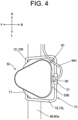
- FIG. 4 is a plan view of the antenna unit 50 and support unit 70.
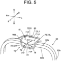
- FIG. 5 is a perspective view of the support unit 70, with the antenna unit 50 in FIG. 3 omitted.
- the support unit 70 functions not only as a support member to support the antenna unit 50, but also functions as a protective member to protect a harness connection portion 51 (see FIG. 4 ) of the antenna unit 50.
- the harness connection portion 51 is to be described.
- the harness connection portion 51 of the antenna unit 50 is a connector (coupler) connected to the harness WH described above.
- the terminal on one end side of the harness WH is connected to the harness connection portion 51, and the terminal on the other end side is connected to the control unit 23 (see FIG. 2 ), thereby to make it possible to electrically connect the antenna unit 50 and the control unit 23.
- various information acquired at the antenna unit 50 can be sent via the harness WH to the outside (herein, the control unit 23).
- the antenna unit 50 has a harness connection portion 51 that is connected to the harness WH for sending information to the outside.
- the harness connection portion 51's position in the antenna unit 50 is not limited, but in the present embodiment, the harness connection portion 51 is positioned at the back portion of the antenna unit 50. This is due to the following reason.
- the harness connection portion 51 is provided on the bottom face of the antenna unit 50 and the harness WH connected to the harness connection portion 51 is caused to pass through the inside of the ROPS frame 60
- providing the hole in the ROPS frame 60 may reduce the strength of the ROPS frame 60.
- the harness WH connected to the harness connection portion 51 can be pulled around outside the ROPS frame 60. Therefore, there is no need to provide the hole in the ROPS frame 60 for the harness WH to pass through. This can prevent the strength of the ROPS frame 60 from being reduced due to drilling of the hole in the ROPS frame 60.
- the harness WH since the harness WH can be pulled around behind the ROPS frame 60, the harness WH does not become an obstacle for the driver operating in the driver seat area 7 in front of the ROPS frame 60.
- the support unit 70 is located protruding from the harness connection portion 51 of the antenna unit 50. Details of the support unit 70 will be described below, but in the present embodiment, a protective pipe 72, which is a protective member of the support unit 70, has a back end located behind the harness connection portion 51 (see FIG. 4 ). From this, it can be said that the support unit 70 having the protective pipe 72 is located protruding backward from the harness connection portion 51.
- the support unit 70 can prevent the harness connection portion 51 of the antenna unit 50, which is fixed to the ROPS frame 60 via the support unit 70 (in particular, the protective pipe 72 described below), from coming into contact with the work instrument 100. This reduces the risk of the harness connection portion 51 coming into contact with the work instrument 100 and being damaged.
- the upper portion of the ROPS frame 60 can turn backward (bendable) so as to prevent the upper portion of the ROPS frame 60 from contacting the upper portion of the barn doorway when the tractor 1 is to be stored in the barn.
- the support unit 70 can prevent the harness connection portion 51 of the antenna unit 50 from coming into contact with the work instrument 100 when the upper portion of the ROPS frame 60 turns backward. Therefore, even when it is so configured that the upper portion of the ROPS frame 60 can turn backward, supporting the antenna unit 50 using the support unit 70 of the present embodiment can reduce the risk of the harness connection portion 51 coming into contact with the work instrument 100 and being damaged.
- the harness connection portion 51 is located protruding backward from a back face 50B of the antenna unit 50.
- the back face 50B refers to ae backward-facing face in the antenna unit 50.
- the harness connection portion 51 When the harness connection portion 51 is located protruding backward from the back face 50B of the antenna unit 50, the harness connection portion 51 may be damaged by contact with the outside. Therefore, so as to prevent the harness connection portion 51 from contacting the work instrument 100, the configuration of the present embodiment, in which the support unit 70 is located more backwardly than the harness connection portion 51, is very effective.
- the harness connection portion 51 of the antenna unit 50 is located behind the ROPS frame 60. That is, the support unit 70 supports the antenna unit 50 so that the harness connection portion 51 is located behind the ROPS frame 60.
- This configuration ensures that the harness WH, which is connected to the harness connection portion 51, can be pulled around behind the ROPS frame 60. Thus, it is possible to reliably distribute the harness WH that becomes the obstacle for the driver operating in the driver seat area 7 in front of the ROPS frame 60.
- FIG. 6 is a perspective view of the support unit 70 seen from below.
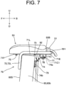
- FIG. 7 is a side view of the support unit 70.
- the support unit 70 has a support plate 71, which is a support member, a protective pipe 72, a fixing plate 73, and a fixing stay 74.
- the support plate 71 is a base to which the antenna unit 50 is fixed and is located below the antenna unit 50.
- a through hole 71P (see FIG. 5 ), which passes through in the vertical direction, is provided at an arbitrary location on the support plate 71.
- the above screwing means that the bolt is turned to join with the nut.
- the support plate 71 is composed of a flat plate with edges.
- the above edges include a front edge 71F protruding forward, a left edge 71L located on the left side and approximately along the front-back direction, a back portion edge 71B located at the back portion and approximately along the left-right direction, and a right edge 71R located on the right side and approximately along the front-back direction.
- the support plate 71 is pentagonal home plate shaped in plan view.
- the support plate 71 may be any other polygonal shape, such as a square, or any shape other than a polygon (circle, oval, etc.) in plan view.
- the support plate 71 is made of metal, such as stainless steel, for example, but may also be made of resin as long as being able to secure strength.
- the protective pipe 72 is a hollow metal pipe and is mounted to a portion of the edge of the support plate 71. More particularly, the protective pipe 72 is mounted to the back portion edge 71B, the left edge 71L and right edge 71R of the support plate 71 by welding or any other operation. Like the support plate 71, the protective pipe 72 may also be made of resin. In this case, any method can be selected for fixing the support plate 71 and the protective pipe 72, such as a method using fixing jigs (bolts and nuts). Details of the protective pipe 72 are described below.
- the fixing plate 73 is located along a front face 60S of the ROPS frame 60 and is fixed to the protective pipe 72 by welding or any other operation.
- the front face 60S of the ROPS frame 60 refers to a face positioned on the front side (the face turning forward) in the transverse frame 60a and longitudinal frame 60b of the ROPS frame 60.
- the fixing plate 73 in the left-right direction, has two through holes (not shown) that pass through in the front-back direction.
- the above through holes are so formed as to correspond to the positions of two front positioning nuts 61 fixed to the ROPS frame 60 (see FIG. 6 ).
- the front positioning nut 61 is composed of a nut having a long through-hole in the front-back direction (so-called high nut), and is welded or otherwise connected to a lower face 60a1 of the transverse frame 60a of the ROPS frame 60. On the lower face 60a1 of the transverse frame 60a, the front positioning nut 61 is located at the front side of the center in the front-back direction.
- the fixing stay 74 is a metal plate used to fix the support plate 71 to the ROPS frame 60.
- the fixing stay 74 is formed by bending both end portions of a single elongated metal plate in a direction that brings them closer together at an angle of approximately 45°.
- one end portion of the fixing stay 74 has a first through-hole 74a that passes through in the vertical direction, and the other end portion has a second through-hole 74b that passes through in the front-back direction.
- a U-shaped metal fitting 71C which is U-shaped in lateral view, is mounted to the lower face of the support plate 71.
- a through hole 71C1 which passes through in the vertical direction, is formed in the bottom face of the U-shaped metal fitting 71C.
- a back positioning nut 62 is welded or otherwise coupled to the lower face 60a1 of the transverse frame 60a of the ROPS frame 60.
- the back positioning nut 62 is composed of a nut (high nut) having a long through-hole in the front-back direction.
- the back positioning nut 62 is located backward of the center in the front-back direction and approximately in the center in the left-right direction.
- a nut 77 (see FIG. 7 ) is located within a space enclosed by the lower face of the support plate 71 and the U-shaped metal fitting 71C, and a third bolt 78 is inserted from below into the first through-hole 74a of the fixing stay 74 and the through hole 71C1 of the metal fitting 71C and screwed with the nut 77.
- a fourth bolt 79 is inserted from the back into the second through-hole 74b of the fixing stay 74 and screwed with the back positioning nut 62 (see FIG. 6 ) fixed to the ROPS frame 60. This fixes the support plate 71 to the ROPS frame 60 via the fixing stay 74.
- the second bolt 76 is used thereby to fix the fixing plate 73 to the ROPS frame 60
- the third bolt 78 and the fourth bolt 79 are used thereby to fix the support plate 71 via the fixing stay 74 to the ROPS frame 60, thereby making it possible to firmly fix the support unit 70 to the ROPS frame 60.
- the protective pipe 72 is composed of a left pipe 72L located to the left of the support plate 71's center in the left-right direction and a right pipe 72R located to the right of the center are connected in the left-right direction in front of the ROPS frame 60 and below the support plate 71. A more detailed description is as follows.
- the left pipe 72L With a start point 72L1 (see FIG. 5 ) defined as a position on the left side of the center of the back portion edge 71B of the support plate 71 in the left-right direction, the left pipe 72L extends to an end portion 71a (see FIG. 6 ) as a left back end portion of the support plate 71.
- the left pipe 72L extends from the end portion 71a of the support plate 71 along the left edge 71L to the front of the ROPS frame 60.
- the left pipe 72L is disconnected from the left edge 71L on the way extending from the end portion 71a of the support plate 71 to the front of the ROPS frame 60.
- the left pipe 72L bends downward along the front face 60S in front of the ROPS frame 60, extends to a position lower than the transverse frame 60a of the ROPS frame 60, and then is bent rightward and connected with the right pipe 72R.
- the right pipe 72R extends to an end portion 71b (see FIG. 6 ) as a right back end portion of the support plate 71.
- the right pipe 72R extends from the end portion 71b of the support plate 71 along the right edge 71R to the front of the ROPS frame 60.
- the right pipe 72R is disconnected from the right edge 71R on the way extending from the end portion 71b of the support plate 71 to the front of the ROPS frame 60.
- the right pipe 72R bends downward along the front face 60S in front of the ROPS frame 60, extends to a position lower than the transverse frame 60a of the ROPS frame 60, and then is bent leftward and connected with the left pipe 72L.
- the start point 72L1 of the left pipe 72L and the start point 72R1 of the right pipe 72R are closed by a closing plate 80 (see FIG. 4 and FIG. 5 ).
- the closing plate 80 is a U-shaped flat plate viewed from the back, and is fixed to the back portion edge 71B of the support plate 71 by welding or any other operation.
- the closing plate 80 is located between the start point 72L1 and the start point 72R1. As a result, the start point 72L1 and the start point 72R1 are positioned spaced apart from each other in the left-right direction.
- the support unit 70 has the protective pipe 72 that is mounted to some of the edges of the support plate 71 (back portion edge 71B, left edge 71L, and right edge 71R).
- the protective pipe 72 is mounted to the back portion of the support plate 71, specifically to the back portion edge 71B, and extends to the left and right.
- the protective pipe 72 is so configured as to extend forward from each of the left and right end portions 71a, 71b of the back portion edge 71B of the support plate 71 along each of the left and right edges 71L, 71R of the support plate 71, and to connect in front of the ROPS frame 60 and in the left-right direction at a position lower than the support plate 71.
- the protective pipe 72 In front of the ROPS frame 60 and below the support plate 71, the protective pipe 72 is located extending in the left-right direction. With this, even when the driver in the driver seat area 7 in front of the ROPS frame 60 stands up and the driver's head portion contacts the support unit 70, the possibility of the driver's head portion coming into contact with the protective pipe 72 located below the support plate 71 is greater than the possibility of the driver's head portion coming into contact with the support plate 71.
- the protective pipe 72 is annular and has a rounded outer surface; therefore, even when the driver's head portion contacts the protective pipe 72, the head portion is less likely to be damaged than when the driver's head portion contacting an edge (e.g., front edge 71F (see FIG. 5 )) of the support plate 71.That is, the protective pipe 72 reduces the damage to the driver's head portion and protects the driver's head portion.
- the tractor 1 of the present embodiment is equipped with a first fixing member 81.
- the first fixing member 81 is a member that fixes, to the support unit 70 (especially, the support plate 71), a portion of the harness WH connected to the harness connection portion 51 of the antenna unit 50.
- the first fixing member 81 is composed of a wiring clamp (wire saddle), for example, but may also be composed of other fixing fixtures such as bands and clips.
- the portion of the harness WH is fixed to the support unit 70 (especially, the support plate 71) by the first fixing member 81, thus stabilizing the pulling around (distributing) of the harness WH.
- the tractor 1 of the present embodiment is further equipped with a second fixing member 82.
- the second fixing member 82 is a member that fixes a portion of the harness WH to the outer surface of the ROPS frame 60.
- Conceivable examples of the outer surface of the ROPS frame 60 include a back face 60a2 (see FIG. 6 ) of the transverse frame 60a of the ROPS frame 60, but the outer surface can also be the upper face of the transverse frame 60a or the outer surface (side face or back face) of the longitudinal frame 60b (see FIG. 1 ).
- the second fixing member 82 is composed of a wiring clamp, for example, but may also be composed of other fixing jigs such as bands, clips, etc.
- the second fixing member 82 may also include a metal fitting that supports the wiring clamp on the outer surface of the ROPS frame 60.
- the second fixing member 82 can pull around the harness WH along the outer surface of the ROPS frame 60. Therefore, compared to the configuration where the harness WH is so pulled around as to pass through the inside of the ROPS frame 60, for example, pulling around of the harness WH is easier. Also, the outer surface of the ROPS frame 60 has no need to form the hole for the harness WH to pass through, as in the configuration where the harness WH is so pulled around as to pass through the inside of the ROPS frame 60. This avoids reduction in strength of the ROPS frame 60. Further, merely unfixing the second fixing member 82 can easily remove the harness WH from the outer surface of the ROPS frame 60, facilitating maintenance of the harness WH.
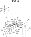
- FIG. 8 is a perspective view schematically showing another configuration of the support unit 70.
- the support unit 70 may be fixed to the ROPS frame 60 in a manner to support the antenna unit 50 in front of the ROPS frame 60.
- the above support unit 70 is so configured as to have a first flat plate portion 201, a second flat plate portion 202, and a coupling portion 203.
- the first flat plate portion 201 is a flat plate that extends in the front-back and left-right directions and is located in front of the ROPS frame 60.
- the antenna unit 50 is fixed to the first flat plate portion 201 from below by bolts or the like. The antenna unit 50 is thus supported from below by the first flat plate portion 201.
- the above first flat plate portion 201 is located at the same height as an upper face 60a3 of the transverse frame 60a of the ROPS frame 60, but may be higher than the upper face 60a3.
- the second flat plate portion 202 is a flat plate that extends in the left-right direction and is located in contact with the lower face 60a1 of the transverse frame 60a of the ROPS frame 60.
- the second flat plate portion 202 is fixed to the lower face 60a1 of the transverse frame 60a by welding or any other operation, but may also be fixed by bolts or the like.
- the coupling portion 203 connects the back end of the first flat plate portion 201 with the front end of the second flat plate portion 202.
- the support unit 70 having the first flat plate portion 201, the second flat plate portion 202, and the coupling portion 203 may be formed by bending a single metal plate. Further, the support unit 70 may be formed in a manner to connect, by welding or otherwise, the first flat plate portion 201 with the coupling portion 203 and the second flat plate portion 202 with the coupling portion 203.
- the antenna unit 50 when the antenna unit 50 is fixed to the ROPS frame 60, which has the upper portion turnable backward, using the support unit 70 shown in FIG. 8 ; before the turning of the ROPS frame 60, the antenna unit 50 is located in front of the ROPS frame 60. Therefore, when the upper portion of the ROPS frame 60 is turned backward, the ROPS frame 60 is likely to come into contact with the work instrument 100 before the antenna unit 50, and the antenna unit 50 is less likely to come into contact with the work instrument 100. Therefore, even when the antenna unit 50 is fixed to the ROPS frame 60, which has the upper portion turnable backward, using the support unit 70 shown in FIG. 8 , the risk of the harness connection portion 51 of the antenna unit 50 coming into contact with the work instrument 100 and being damaged can be reduced.
- the lower face 60a1 of the transverse frame 60A of the ROPS frame 60 may have an insertion hole 60P.
- the harness WH which is connected to the harness connection portion 51 of the antenna unit 50, may be distributed via the insertion hole 60P through the inside of the ROPS frame 60.
- the strength of the ROPS frame 60 may be reduced when the ROPS frame 60 is configured to be provided with the insertion hole 60P; however, appropriately selecting the material or the like of the ROPS frame 60 can secure the minimum necessary strength of the ROPS frame 60. Therefore, on condition that the strength of the ROPS frame 60 should be secured, providing the ROPS frame 60 with the insertion hole 60P and causing the harness WH to pass through the inside of the ROPS frame 60 via the insertion hole 60P can prevent appearance quality deterioration due to the harness WH's exposure to the outside.
- the insertion hole 60P is formed on the lower face 60a1 of the ROPS frame 60 (transverse frame 60a), rainwater falling from above, water during vehicle washing, mud, etc. are unlikely to penetrate into the inside of the ROPS frame 60 through the insertion hole 60P. Thus, corrosion of the harness WH due to water and other elements entering the inside of the ROPS frame 60 can be reduced.
- the insertion hole 60P may be formed on the back face 60a2 of the ROPS frame 60 (e.g., transverse frame 60A).
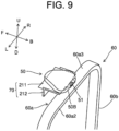
- FIG. 9 is a perspective view showing still another configuration of the support unit 70.
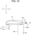
- FIG. 10 is a side view of the support unit 70 in FIG. 9 .
- the support unit 70 may be configured to support the antenna unit 50 so that the harness connection portion 51 of the antenna unit 50 overlaps the ROPS frame 60 when viewed from above.
- the 51 harness connection portions overlaps with the ROPS frame 60 viewed from above means that all of the harness connection portions 51 overlap the ROPS frame 60 (especially, the transverse frame 60a) when viewed from above. This means that, when viewed from above, the harness connection portion 51 is located between the upper portion of the front face 60S of the ROPS frame 60 and the upper portion of the back face 60a2.
- the support unit 70 is so configured as to have a support stand 211 and a fixing stay 212.
- the antenna unit 50 is fixed to the support stand 211 from below by bolts or the like.
- the antenna unit 50 is thus supported from below by the support stand 211.
- the fixing stay 212 is L-shaped in lateral view and is fixed to the support stand 211 by welding or any other operation, thereby to support the support stand 211 from below. Also, the fixing stay 212 is fixed to the upper face 60a3 of the transverse frame 60a of the ROPS frame 60 by welding or any other operation.
- the harness connection portion 51 of the antenna unit 50 is located in a manner to overlap the ROPS frame 60 viewed from above; therefore, even when the work instrument 100 (see FIG. 1 ) is raised, the above prevents the harness connection portion 51 of the antenna unit 50 from coming into contact with the work instrument 100. As a result, the risk of the harness connection portion 51 coming into contact with the work instrument 100 and being damaged can be reduced.
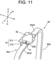
- FIG. 11 is a perspective view schematically showing still another configuration of the support unit 70.
- FIG. 12 is a side view of the support unit 70 in FIG. 11 .
- the support unit 70 is common to FIG. 9 in supporting the antenna unit 50 so that the harness connection portion 51 of the antenna unit 50 overlaps the ROPS frame 60, viewed from above.
- the difference from FIG. 9 is that the support unit 70 supports the antenna unit 50 by 90° turning the antenna unit 50 to the right from the position in FIG. 9 by. So as to realize the configuration where the support unit 70 supports the antenna unit 50 so that the harness connection portion 51 overlaps the ROPS frame 60; as shown in FIGS. 11 and 12 , the position of fixing the fixing stay 212 to the ROPS frame 60 by welding or the like is shifted backward from the position shown in FIGS. 9 and 10 .
- the support unit 70 may support the antenna unit 50 by 90° turning the antenna unit 50 to the left from the position in FIG. 9 . If the harness connection portion 51 overlaps the ROPS frame 60 when viewed from above, the turning angle of the antenna unit 50 from the position in FIG. 9 is not limited to 90° described above, but may be any other angle.
- the harness connection portion 51 is so located as to overlap the ROPS frame 60 when viewed from above; therefore, even when the work instrument 100 (see FIG. 1 ) is raised, the harness connection portion 51 of the antenna unit 50 is prevented from coming into contact with the work instrument 100, making it possible to reduce the risk of damage to the harness connection portion 51.
- the support unit 70 of FIG. 11 is applied to the ROPS frame 60 whose upper portion is turnable backward, the risk of the harness connection portion 51 coming into contact with the work instrument 100 and being damaged can be reduced when the upper portion of the ROPS frame 60 turns backward.
- FIG. 13 is a perspective view schematically showing still another configuration of the support unit 70.
- the support unit 70 may be configured to turn the antenna unit 50.
- the support unit 70 is so configured as to have a support pipe 221 and a turn plate 222.
- the support pipe 221 is so configured as to extend below the transverse frame 60a of the ROPS frame 60 in the left-right direction and to bend downward near the longitudinal frame 60b. Both ends of the support pipe 221 are fixed to the longitudinal frame 60b by a fixing member 223.
- the turn plate 222 is so configured as to have a metal plate 222a that is inverted U-shaped viewed from the back, and a support plate 222b connected to the upper portion of the metal plate 222a and extending forward.
- the metal plate 222a is located behind the transverse frame 60a of the ROPS frame 60. In the left and right directions, the metal plate 222a has two insertion holes 222a1 through which the support pipe 221 is inserted.
- the antenna unit 50 is fixed to the support plate 222b by bolts or the like. As a result, the antenna unit 50 is supported from below by the support plate 222b.
- the support pipe 221 is inserted through the insertion hole 222a1 of the metal plate 222a of the turn plate 222, so the turn plate 222 is turnable with the support pipe 221, which extends in the left-right direction, as the rotational axis.
- the support pipe 221 itself does not rotate.
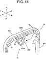
- FIG. 14 shows a state seen after turning the turn plate 222.
- the turn plate 222 turns so that the antenna unit 50 supported by the support plate 222b passes behind the ROPS frame 60.
- the antenna unit 50 supported by the support plate 222b can be located in front of the ROPS frame 60. Therefore, even when the work instrument 100 (see FIG. 1 ) is raised, the harness connection portion 51 of the antenna unit 50 is prevented from coming into contact with the work instrument 100, thereby reducing the risk of damage to the harness connection portion 51.
- the turning of the turn plate 222 moves the antenna unit 50 to a lower position (the overall height of the tractor 1 is lowered). At the time of storing the tractor 1 in a barn, this allows the tractor 1 to be stored in a barn without the antenna unit 50 contacting the upper portion of the barn entrance. Further, the turn plate 222 turns such that the antenna unit 50 passes behind the ROPS frame 60, thus preventing as much as possible the antenna unit 50 from interfering (having a contact) with the driver in the driver seat area 7 in front of the ROPS frame 60.
- the metal plate 222a of the turn plate 222 may be located in front of the transverse frame 60a. Then, the turn plate 222 is so configured as to rotate such that the antenna unit 50 passes in front of the ROPS frame 60. Even with this configuration; after the turning of the turn plate 222, the antenna unit 50, which is supported by the support plate 222b, can be located in front of the ROPS frame 60. Therefore, even when the work instrument 100 is raised, the harness connection portion 51 of the antenna unit 50 is prevented from contacting the work instrument 100, making it possible to reduce the risk of damage to the harness connection portion 51.
- FIG. 15 is a perspective view schematically showing still another configuration of the support unit 70.
- the support unit 70 may be configured to rotate the antenna unit 50 in combination with the support pipe 231 as a whole.
- the support unit 70 is so configured as to have the support pipe 231, a turn plate 232, and a hinge portion 233.
- the support pipe 231 is so configured as to extend in front of the transverse frame 60a of the ROPS frame 60 in the left-right direction, and to be bent downward near the longitudinal frame 60b. Both ends of the support pipe 231 are fixed to the longitudinal frame 60b via the hinge portion 233.
- the turn plate 232 is fixed to the support pipe 231 by welding or any other operation.
- the antenna unit 50 is fixed to the turn plate 232 by bolts or the like. The antenna unit 50 is thus supported from below by the turn plate 232.
- the hinge portion 233 is a turn mechanism by which the support pipe 231 is rotatably connected to the ROPS frame 60 (particularly longitudinal frame 60b).
- the hinge portion 233 allows the support pipe 231 to rotate relative to the ROPS frame 60, with the left and right directions as the rotational axis.
- FIG. 16 shows a state seen after the support pipe 231 is rotated together with the turn plate 232.
- the turn plate 232 is rotated together with the support pipe 231 so that the antenna unit 50 supported by the turn plate 232 passes in front of the ROPS frame 60.
- the harness connection portion 51 (see FIG. 15 ) of the antenna unit 50 supported by the turn plate 232 can be located in front of the ROPS frame 60.
- the antenna unit 50 moves to a lower position due to the turning of the turn plate 232; therefore, at the time of storing the tractor 1 in the barn, the tractor 1 can be stored in the barn without the antenna unit 50 coming in contact with the upper portion of the barn entrance.
- the hinge portion 233 allows the support pipe 231 to turn together with the turn plate 232 and to move to the lower position, so that, after the turning, the backward view from the driver in the driver seat area 7 can be widely secured (the backward view is not obstructed by the support pipe 231). This makes it easier for the driver to visually check the back.
- the support pipe 231 may be located backward of the transverse frame 60a. Then, it may be so configured that the turn plate 232 turns together with the support pipe 231 such that the antenna unit 50 passes behind the ROPS frame 60. Even with this configuration, after the turning of the turn plate 232, the harness connection portion 51 of the antenna unit 50 supported by the turn plate 232 can be located in front of the ROPS frame 60. Therefore, even when the work instrument 100 is raised, the harness connection portion 51 is prevented from contacting the work instrument 100, making it possible to reduce the risk of damage to the harness connection portion 51.
- the present invention can be used for a work vehicle such as tractor, for example.
Landscapes
- Engineering & Computer Science (AREA)
- Mechanical Engineering (AREA)
- Remote Sensing (AREA)
- Life Sciences & Earth Sciences (AREA)
- Environmental Sciences (AREA)
- Soil Sciences (AREA)
- Combustion & Propulsion (AREA)
- Transportation (AREA)
- Chemical & Material Sciences (AREA)
- Radar, Positioning & Navigation (AREA)
- Body Structure For Vehicles (AREA)
- Support Of Aerials (AREA)
- Position Fixing By Use Of Radio Waves (AREA)
- Fittings On The Vehicle Exterior For Carrying Loads, And Devices For Holding Or Mounting Articles (AREA)
- Guiding Agricultural Machines (AREA)
Abstract
Description
- The present invention relates to a work vehicle such as tractor.
- Conventionally, there has been proposed a technology that installs a positioning unit that detects the position of a vehicle body in a roll-over protection structure (ROPS) frame of a tractor (see, for example, Patent Document 1). The ROPS frame is a guard provided around a driver seat area so as to protect the driver in the event of a fall in a tractor without a ceiling and pillars to support the ceiling, and is erected in an inverted U shape at the back of the driver seat area on the vehicle body, for example.
- Patent Document 1:
Japanese Unexamined Patent Application Publication No. 2019-108003 - The information acquired by the positioning unit (e.g., position information of tractor) is sent to a controller via a harness. For example, if a connection portion with a harness (hereinafter referred to as "harness connection portion") is provided at the back portion of the positioning unit; when a work instrument connected to the back of the tractor body is raised while the positioning unit is fixed to the upper portion of the ROPS frame, there is a risk of the harness connection portion of the positioning unit coming into contact with the work instrument and being damaged.
- The present invention has been made to solve the above problem; it is therefore an object of the present invention to provide a work vehicle that can reduce the risk of the harness connection portion of the positioning unit coming into contact with the work instrument and being damaged.
- A work vehicle according to one aspect of the present invention includes: a vehicle body to which a work instrument is connected at a back; and a ROPS frame erected at a back portion of a driver seat area in the vehicle body, wherein the work vehicle further includes: a positioning unit that detects a position of the vehicle body based on a signal sent from a positioning satellite, and a support unit that is fixed to an upper portion of the ROPS frame and supports the positioning unit from below, wherein the positioning unit has a harness connection portion that is connected to a harness for sending information to outside, and wherein the harness connection portion is located at a back portion of the positioning unit, and wherein the support unit is located protruding backwardly from the harness connection portion of the positioning unit.
- The above configuration can reduce the risk the harness connection portion of the positioning unit coming into contact with the work instrument and being damaged.
-
-
FIG. 1 is a schematic side view of a configuration of a tractor which is an example of a work vehicle according to an embodiment of the present invention. -
FIG. 2 is a block diagram of a vehicle travel system including the tractor. -
FIG. 3 is a perspective view of an antenna unit and support unit mounted on the tractor seen from above. -
FIG. 4 is a plan view of the support unit. -
FIG. 5 is a perspective view of the support unit with the antenna unit inFIG. 3 omitted. -
FIG. 6 is a perspective view of the support unit seen from below. -
FIG. 7 is a side view of the support unit. -
FIG. 8 is a perspective view schematically showing another configuration of the support unit. -
FIG. 9 is a perspective view schematically showing still another configuration of the support unit. -
FIG. 10 is a side view of the support unit inFIG. 9 . -
FIG. 11 is a perspective view schematically showing still another configuration of the support unit. -
FIG. 12 is a side view of the support unit inFIG. 11 . -
FIG. 13 is a perspective view schematically showing still another configuration of the support unit. -
FIG. 14 is a perspective view of the support unit inFIG. 13 , showing a state seen after turning a turn plate. -
FIG. 15 is a perspective view schematically showing still another configuration of the support unit. -
FIG. 16 is a perspective view of the support unit inFIG. 15 , showing a state seen after turning the turn plate and a support pipe. - The following is a description of an embodiment of the present invention based on the drawings. In the present embodiment, a tractor will be described as an example of a work vehicle. In addition to the tractor, examples of the work vehicle include riding work vehicles such as a rice transplanter, a combine harvester, a civil engineering and construction work device, and a snowplow.
- In this description, directions are defined as follows. First, the direction in which the tractor as the work vehicle proceeds during work is defined as "front" and the opposite direction is defined as "back". The right side toward the proceeding direction of the tractor is defined as right, and the left side is defined as left. The direction perpendicular to the front-back and left-right directions of the tractor is defined as a vertical direction. In this case, the direction of gravity is downward and the opposite side is upward. In the drawings, the front direction is indicated by F, the back direction by B, the left direction by L, the right direction by R, the upward direction by U, and the downward direction by D.
-
FIG. 1 is a schematic side view of a tractor 1 which is an example of a work vehicle of the present embodiment.FIG. 2 is a block diagram of a vehicle travel system including the tractor 1. - As shown in
FIG. 2 , the vehicle travel system is composed of the tractor 1, awireless communication terminal 30, and areference station 40. The tractor 1 can travel according to the operation of the driver or can travel autonomously based on an instruction or the like from thewireless communication terminal 30. Thewireless communication terminal 30 is a terminal for giving various instructions, etc. to the tractor 1. Thereference station 40 is provided so as to obtain position information of the tractor 1. - As shown in
FIG. 1 , the tractor 1 includes avehicle body 2. At the back of thevehicle body 2, awork instrument 100 can be mounted. That is, the tractor 1 is equipped with thevehicle body 2 to whichwork instrument 100 is connected at the back. Thework instrument 100 can be, for example, but is not limited to, cultivators, plows, and fertilizer application equipment. - The front portion of the
vehicle body 2 is supported by a pair of left-rightfront wheels 3. The back portion of thevehicle body 2 is supported by a pair of left-right back wheels 4. In the front portion of thevehicle body 2, a hood 5 is located. An engine 6 as a drive source is located below the hood 5. The engine 6 is composed of a diesel engine, for example, but is not limited to this and may be composed of a gasoline engine, for example. In addition to or instead of the engine 6, an electric motor may be used as the drive source. - In the upper center portion in the front-back direction in the
vehicle body 2, a driver seat area 7 is provided for a man operator (driver). The driver seat area 7 is equipped with asteering wheel 8 for the driver to make a steering operation, and adriver seat 9 for the driver. Although not shown in the drawing, the driver seat area 7 is provided with control levers, pedals, etc. operated by the driver. - A three-point link mechanism is provided on the back side of the
vehicle body 2. The three-point link mechanism is composed of a pair of left-rightlower links 10 and anupper link 11. Thework instrument 100 is configured to be mountable to the three-point link mechanism. A raising-lowering device (not shown) with a hydraulic system such as a lifting cylinder is provided at the back side of thevehicle body 2. The raising-lowering device raises and lowers the three-point link mechanism, thereby making it possible to raise and lower thework instrument 100. - In the
vehicle body 2, aROPS frame 60 is provided at the back portion of the driver seat area 7 (driver seat 9). TheROPS frame 60 is a safety frame (guard) provided for the purpose of protecting the man operator in the event that the tractor 1 tips over, as described above. TheROPS frame 60 is composed of a hollow frame, and is erected in an inverted U-shape at the back portion of the driver seat area 7. That is, the tractor 1 is equipped with theROPS frame 60 that is erected at the back portion of the driver seat area 7 in thevehicle body 2. The height of theROPS frame 60 can be set as needed within the range specified by the regulations. - The
ROPS frame 60 is so configured that twolongitudinal frames 60b extending in the vertical direction are each connected to one end of thetransverse frame 60a (seeFIG. 3 , etc.) extending in the left-right direction. The coupling portion between thetransverse frame 60a and thelongitudinal frame 60b is rounded (curvature). This results in the invertedU-shaped ROPS frame 60 described above. - As shown in
FIG. 2 , tractor 1 is provided with agovernor unit 21 that can adjust the rotational speed of engine 6 and atransmission unit 22 that changes the speed and transmits the rotational drive power from the engine 6 to the drive wheels. Thegovernor unit 21 andtransmission unit 22 are controlled by acontrol unit 23. - The tractor 1 is equipped with a
steering unit 24. Thesteering unit 24 is provided, for example, at the midpoint of the rotational axis of thesteering wheel 8 and is configured to adjust the rotational angle (steering angle) of thesteering wheel 8. By thecontrol unit 23 controlling thesteering unit 24, the tractor 1 can not only drive straight ahead, but also turn thesteering wheel 8 at a desired angle, and can make a turn at a desired turning radius. - The tractor 1 is further equipped with an
antenna unit 50. Theantenna unit 50 is a positioning unit that detects the position ofvehicle body 2 based on a signal sent from a positioning satellite (navigation satellite) 45 shown inFIG. 1 . - The
antenna unit 50 and thecontrol unit 23 are electrically connected by a harness WH. This can send various information or instructions between theantenna unit 50 and thecontrol unit 23 via the harness WH. For example, thevehicle body 2's position information detected by theantenna unit 50 is input to thecontrol unit 23 via the harness WH. - Details of the
antenna unit 50 are described below. Theantenna unit 50 has an inertial measurement unit (IMU) 25, a GNSS (Global Navigation Satellite System)antenna 26, awireless communication unit 27, awireless communication antenna 28, and abase station antenna 29. - The
inertial measurement unit 25 is equipped with a 3-axis gyro sensor and a 3-way accelerometer, which detects angular velocity and acceleration in three dimensions. The detected value of theinertial measurement unit 25 is input to thecontrol unit 23. Thecontrol unit 23 can obtain the attitude information of the tractor 1 based on the above detected value. The above attitude information includes, for example, the azimuth angle of a machine body (yaw angle), the left-right tilt angle of the machine body (roll angle), and the front-back tilt angle in the direction where the machine body is proceeding (pitch angle). - The
GNSS antenna 26 receives radio signals sent from apositioning satellite 45 that forms a satellite positioning system (GNSS). In the satellite positioning system, in addition to GPS (Global Positioning System; U.S.), Quasi-Zenith Satellite System (Japan), GLONASS satellite (Russia) or the like can be used as positioning satellites. - The
wireless communication unit 27 sends and receives various signals via a wireless communication network formed in combination with thewireless communication terminal 30 and other devices. In the present embodiment, thewireless communication unit 27 is a Wifi (registered trademark) unit with a frequency band of 2.4 GHz. Signals sent from thewireless communication terminal 30 are received by thewireless communication antenna 28 and, and are input to thecontrol unit 23 via thewireless communication unit 27. In addition, signals from thecontrol unit 23 are sent via thewireless communication unit 27 and thewireless communication antenna 28 to awireless communication unit 31, etc. of thewireless communication terminal 30. - Here, for example, RTK (Real Time Kinematic) positioning is used in the present embodiment, as a positioning method using the satellite positioning system. In the RTK positioning, the carrier phase (satellite positioning information) from the
positioning satellites 45 is measured by both of a referencestation positioning antenna 42 of thereference station 40 installed at the reference point, and theGNSS antenna 26 of the tractor 1 that is on the mobile station side of the target for which the position information is sought. At thereference station 40, correction information is generated each time the satellite positioning information is measured from thepositioning satellite 45, or each time a set period elapses. The above correction information is sent from a reference stationradio communication unit 41 to thebase station antenna 29 of the tractor 1. Using the correction information sent from thereference station 40, thecontrol unit 23 of the tractor 1 corrects the satellite positioning information measured by theGNSS antenna 26, thereby to seek the current position information of the tractor 1. Thecontrol unit 23 seeks, for example, latitude information and longitude information as the current position information of the tractor 1. - The positioning method used is not limited to the RTK positioning described above, and other positioning methods such as DGPS (differential GPS positioning) may also be used. Further, the
reference station 40 can send and receive various information not only to and from the tractor 1, but also to and from thewireless communication terminal 30. - The
wireless communication terminal 30 is composed of, for example, a tablet type personal computer having a touch screen, and the like. Thewireless communication terminal 30 is provided with awireless communication unit 31 and aroute generating unit 32 that generates a target travel route. Based on various information input at the touch screen, theroute generating unit 32 can generate the target travel route for autonomous driving of the tractor 1. Theroute generating unit 32 is composed of a CPU (Central Processing Unit), for example, owned by the personal computer. - The
wireless communication terminal 30 sends various information to the tractor 1 for autonomous driving of the tractor 1, such as the target travel route. Thecontrol unit 23 of the tractor 1 controls thetransmission unit 22, thesteering unit 24, etc., based on the tractor 1's current position information required from receiving signals, etc., of theGNSS antenna 26 and on thevehicle body 2's attitude information (displacement information, orientation information) required from the detected value at theinertial measurement unit 25. This allows the tractor 1 to travel autonomously along the target travel route generated by theroute generating unit 32. - As shown in
FIG. 1 , the tractor 1 is further equipped with asupport unit 70. Thesupport unit 70 is fixed to the upper portion of theROPS frame 60, and supports theantenna unit 50 from below. Theantenna unit 50 is thus fixed to the upper portion of theROPS frame 60 via thesupport unit 70. - In the present embodiment, from the viewpoint of reducing the effect of the tractor 1's vibration on the position detection accuracy of the
antenna unit 50, theantenna unit 50 is supported by thesupport unit 70 so that the gravitational center of theantenna unit 50 is located in theROPS frame 60's center in the front-back direction. Details of the configuration of thesupport unit 70 are described below. -
FIG. 3 is a perspective view of theantenna unit 50 and thesupport unit 70 seen from above, with theantenna unit 50 fixed to theROPS frame 60 via thesupport unit 70.FIG. 4 is a plan view of theantenna unit 50 andsupport unit 70.FIG. 5 is a perspective view of thesupport unit 70, with theantenna unit 50 inFIG. 3 omitted. In the present embodiment, thesupport unit 70 functions not only as a support member to support theantenna unit 50, but also functions as a protective member to protect a harness connection portion 51 (seeFIG. 4 ) of theantenna unit 50. Herein, theharness connection portion 51 is to be described. - As shown in
FIG. 4 , theharness connection portion 51 of theantenna unit 50 is a connector (coupler) connected to the harness WH described above. The terminal on one end side of the harness WH is connected to theharness connection portion 51, and the terminal on the other end side is connected to the control unit 23 (seeFIG. 2 ), thereby to make it possible to electrically connect theantenna unit 50 and thecontrol unit 23. Then, various information acquired at the antenna unit 50 (position information, correction information, posture information, etc.) can be sent via the harness WH to the outside (herein, the control unit 23). Thus, theantenna unit 50 has aharness connection portion 51 that is connected to the harness WH for sending information to the outside. - The
harness connection portion 51's position in theantenna unit 50 is not limited, but in the present embodiment, theharness connection portion 51 is positioned at the back portion of theantenna unit 50. This is due to the following reason. - For example, in a configuration where the
harness connection portion 51 is provided on the bottom face of theantenna unit 50 and the harness WH connected to theharness connection portion 51 is caused to pass through the inside of theROPS frame 60, it is necessary to provide a hole, which is used for the harness WH to pass through, on the upper face of the ROPS frame 60 (the face in contact with the bottom face of the antenna unit 50). There is a concern that providing the hole in theROPS frame 60 may reduce the strength of theROPS frame 60. - In the configuration where the
harness connection portion 51 is located at the back portion of theantenna unit 50, as in the present embodiment, the harness WH connected to theharness connection portion 51 can be pulled around outside theROPS frame 60. Therefore, there is no need to provide the hole in theROPS frame 60 for the harness WH to pass through. This can prevent the strength of theROPS frame 60 from being reduced due to drilling of the hole in theROPS frame 60. In addition, since the harness WH can be pulled around behind theROPS frame 60, the harness WH does not become an obstacle for the driver operating in the driver seat area 7 in front of theROPS frame 60. - As shown in
FIG. 4 , thesupport unit 70 is located protruding from theharness connection portion 51 of theantenna unit 50. Details of thesupport unit 70 will be described below, but in the present embodiment, a protective pipe 72, which is a protective member of thesupport unit 70, has a back end located behind the harness connection portion 51 (seeFIG. 4 ). From this, it can be said that thesupport unit 70 having the protective pipe 72 is located protruding backward from theharness connection portion 51. - With such a positional relation between the
antenna unit 50 and thesupport unit 70; even when the work instrument 100 (seeFIG. 1 ) connected to the back of thevehicle body 2 is raised, thesupport unit 70 can prevent theharness connection portion 51 of theantenna unit 50, which is fixed to theROPS frame 60 via the support unit 70 (in particular, the protective pipe 72 described below), from coming into contact with thework instrument 100. This reduces the risk of theharness connection portion 51 coming into contact with thework instrument 100 and being damaged. - For example, it can be so configured that the upper portion of the
ROPS frame 60 can turn backward (bendable) so as to prevent the upper portion of theROPS frame 60 from contacting the upper portion of the barn doorway when the tractor 1 is to be stored in the barn. Even when theantenna unit 50 is fixed via thesupport unit 70 to theROPS frame 60 with the above configuration, thesupport unit 70 can prevent theharness connection portion 51 of theantenna unit 50 from coming into contact with thework instrument 100 when the upper portion of theROPS frame 60 turns backward. Therefore, even when it is so configured that the upper portion of theROPS frame 60 can turn backward, supporting theantenna unit 50 using thesupport unit 70 of the present embodiment can reduce the risk of theharness connection portion 51 coming into contact with thework instrument 100 and being damaged. - In particular, the
harness connection portion 51 is located protruding backward from aback face 50B of theantenna unit 50. Theback face 50B refers to ae backward-facing face in theantenna unit 50. - When the
harness connection portion 51 is located protruding backward from theback face 50B of theantenna unit 50, theharness connection portion 51 may be damaged by contact with the outside. Therefore, so as to prevent theharness connection portion 51 from contacting thework instrument 100, the configuration of the present embodiment, in which thesupport unit 70 is located more backwardly than theharness connection portion 51, is very effective. - As shown in
FIG. 4 , with theantenna unit 50 fixed to theROPS frame 60 via thesupport unit 70, theharness connection portion 51 of theantenna unit 50 is located behind theROPS frame 60. That is, thesupport unit 70 supports theantenna unit 50 so that theharness connection portion 51 is located behind theROPS frame 60. - This configuration ensures that the harness WH, which is connected to the
harness connection portion 51, can be pulled around behind theROPS frame 60. Thus, it is possible to reliably distribute the harness WH that becomes the obstacle for the driver operating in the driver seat area 7 in front of theROPS frame 60. - Details of the configuration of the
support unit 70 described above will now be described based onFIGS. 6 and7 , with reference toFIGS. 3 through 5 .FIG. 6 is a perspective view of thesupport unit 70 seen from below.FIG. 7 is a side view of thesupport unit 70. Thesupport unit 70 has asupport plate 71, which is a support member, a protective pipe 72, a fixingplate 73, and a fixingstay 74. - The
support plate 71 is a base to which theantenna unit 50 is fixed and is located below theantenna unit 50. In the present embodiment, a throughhole 71P (seeFIG. 5 ), which passes through in the vertical direction, is provided at an arbitrary location on thesupport plate 71. In the present embodiment, there are three throughholes 71P in thesupport plate 71, but the number of throughholes 71P is not particularly limited. Inserting a first bolt 75 (seeFIGS. 6 and7 ) into the throughhole 71P from the opposite side of theantenna unit 50 and screwing thefirst bolt 75 with a nut (not shown) provided on theantenna unit 50 side fixes theantenna unit 50 to thesupport plate 71. That is, theantenna unit 50 is supported from below by thesupport plate 71. Therefore, thesupport unit 70 can be said to have thesupport plate 71 that supports theantenna unit 50 from below. The above screwing means that the bolt is turned to join with the nut. - As shown in
FIGS. 5 and6 , thesupport plate 71 is composed of a flat plate with edges. The above edges include afront edge 71F protruding forward, aleft edge 71L located on the left side and approximately along the front-back direction, aback portion edge 71B located at the back portion and approximately along the left-right direction, and aright edge 71R located on the right side and approximately along the front-back direction. As a result, thesupport plate 71 is pentagonal home plate shaped in plan view. Thesupport plate 71 may be any other polygonal shape, such as a square, or any shape other than a polygon (circle, oval, etc.) in plan view. Thesupport plate 71 is made of metal, such as stainless steel, for example, but may also be made of resin as long as being able to secure strength. - The protective pipe 72 is a hollow metal pipe and is mounted to a portion of the edge of the
support plate 71. More particularly, the protective pipe 72 is mounted to theback portion edge 71B, theleft edge 71L andright edge 71R of thesupport plate 71 by welding or any other operation. Like thesupport plate 71, the protective pipe 72 may also be made of resin. In this case, any method can be selected for fixing thesupport plate 71 and the protective pipe 72, such as a method using fixing jigs (bolts and nuts). Details of the protective pipe 72 are described below. - The fixing
plate 73 is located along afront face 60S of theROPS frame 60 and is fixed to the protective pipe 72 by welding or any other operation. Thefront face 60S of theROPS frame 60 refers to a face positioned on the front side (the face turning forward) in thetransverse frame 60a andlongitudinal frame 60b of theROPS frame 60. - The fixing
plate 73, in the left-right direction, has two through holes (not shown) that pass through in the front-back direction. In the fixingplate 73, the above through holes are so formed as to correspond to the positions of twofront positioning nuts 61 fixed to the ROPS frame 60 (seeFIG. 6 ). Thefront positioning nut 61 is composed of a nut having a long through-hole in the front-back direction (so-called high nut), and is welded or otherwise connected to a lower face 60a1 of thetransverse frame 60a of theROPS frame 60. On the lower face 60a1 of thetransverse frame 60a, thefront positioning nut 61 is located at the front side of the center in the front-back direction. - Therefore, inserting the second bolt 76 (see
FIGS. 3 and5 ) from the front into the above through hole of the fixingplate 73 and screwing thesecond bolt 76 with thefront positioning nut 61 of theROPS frame 60 can fix the fixingplate 73 to theROPS frame 60. - The fixing
stay 74 is a metal plate used to fix thesupport plate 71 to theROPS frame 60. The fixingstay 74 is formed by bending both end portions of a single elongated metal plate in a direction that brings them closer together at an angle of approximately 45°. InFIG. 7 , one end portion of the fixingstay 74 has a first through-hole 74a that passes through in the vertical direction, and the other end portion has a second through-hole 74b that passes through in the front-back direction. - A U-shaped metal fitting 71C, which is U-shaped in lateral view, is mounted to the lower face of the
support plate 71. A through hole 71C1, which passes through in the vertical direction, is formed in the bottom face of the U-shaped metal fitting 71C. - As shown in
FIG. 6 , aback positioning nut 62 is welded or otherwise coupled to the lower face 60a1 of thetransverse frame 60a of theROPS frame 60. Theback positioning nut 62 is composed of a nut (high nut) having a long through-hole in the front-back direction. On the lower face 60a1 of thetransverse frame 60a, theback positioning nut 62 is located backward of the center in the front-back direction and approximately in the center in the left-right direction. - A nut 77 (see
FIG. 7 ) is located within a space enclosed by the lower face of thesupport plate 71 and the U-shaped metal fitting 71C, and athird bolt 78 is inserted from below into the first through-hole 74a of the fixingstay 74 and the through hole 71C1 of the metal fitting 71C and screwed with the nut 77.In addition, afourth bolt 79 is inserted from the back into the second through-hole 74b of the fixingstay 74 and screwed with the back positioning nut 62 (seeFIG. 6 ) fixed to theROPS frame 60. This fixes thesupport plate 71 to theROPS frame 60 via the fixingstay 74. - As described above, the
second bolt 76 is used thereby to fix the fixingplate 73 to theROPS frame 60, and thethird bolt 78 and thefourth bolt 79 are used thereby to fix thesupport plate 71 via the fixingstay 74 to theROPS frame 60, thereby making it possible to firmly fix thesupport unit 70 to theROPS frame 60. - Details of the protective pipe 72 are described next. The protective pipe 72 is composed of a left pipe 72L located to the left of the
support plate 71's center in the left-right direction and a right pipe 72R located to the right of the center are connected in the left-right direction in front of theROPS frame 60 and below thesupport plate 71. A more detailed description is as follows. - With a start point 72L1 (see
FIG. 5 ) defined as a position on the left side of the center of theback portion edge 71B of thesupport plate 71 in the left-right direction, the left pipe 72L extends to anend portion 71a (seeFIG. 6 ) as a left back end portion of thesupport plate 71. The left pipe 72L extends from theend portion 71a of thesupport plate 71 along theleft edge 71L to the front of theROPS frame 60. The left pipe 72L is disconnected from theleft edge 71L on the way extending from theend portion 71a of thesupport plate 71 to the front of theROPS frame 60. The left pipe 72L bends downward along thefront face 60S in front of theROPS frame 60, extends to a position lower than thetransverse frame 60a of theROPS frame 60, and then is bent rightward and connected with the right pipe 72R. - With the start point 72R1 (see
FIG. 5 ) defined as a position on the right side of the center of theback portion edge 71B of thesupport plate 71 in the left-right direction, the right pipe 72R extends to anend portion 71b (seeFIG. 6 ) as a right back end portion of thesupport plate 71. The right pipe 72R extends from theend portion 71b of thesupport plate 71 along theright edge 71R to the front of theROPS frame 60. The right pipe 72R is disconnected from theright edge 71R on the way extending from theend portion 71b of thesupport plate 71 to the front of theROPS frame 60. The right pipe 72R bends downward along thefront face 60S in front of theROPS frame 60, extends to a position lower than thetransverse frame 60a of theROPS frame 60, and then is bent leftward and connected with the left pipe 72L. - The start point 72L1 of the left pipe 72L and the start point 72R1 of the right pipe 72R are closed by a closing plate 80 (see
FIG. 4 andFIG. 5 ). The closingplate 80 is a U-shaped flat plate viewed from the back, and is fixed to theback portion edge 71B of thesupport plate 71 by welding or any other operation. The closingplate 80 is located between the start point 72L1 and the start point 72R1. As a result, the start point 72L1 and the start point 72R1 are positioned spaced apart from each other in the left-right direction. - As described above, the
support unit 70 has the protective pipe 72 that is mounted to some of the edges of the support plate 71 (backportion edge 71B, leftedge 71L, andright edge 71R). The protective pipe 72 is mounted to the back portion of thesupport plate 71, specifically to theback portion edge 71B, and extends to the left and right. - Mounting the annular protective pipe 72 to some of the edges of the
support plate 71 can reinforce thesupport plate 71 and thus thesupport unit 70. With this, even when the work instrument 100 (seeFIG. 1 ) rises and collides with thesupport unit 70, the risk of damage to thesupport unit 70 can be securely reduced. Thus, theharness connection portion 51 can be reliably protected by thesupport unit 70. - The protective pipe 72 is so configured as to extend forward from each of the left and
right end portions back portion edge 71B of thesupport plate 71 along each of the left andright edges support plate 71, and to connect in front of theROPS frame 60 and in the left-right direction at a position lower than thesupport plate 71. - In front of the
ROPS frame 60 and below thesupport plate 71, the protective pipe 72 is located extending in the left-right direction. With this, even when the driver in the driver seat area 7 in front of theROPS frame 60 stands up and the driver's head portion contacts thesupport unit 70, the possibility of the driver's head portion coming into contact with the protective pipe 72 located below thesupport plate 71 is greater than the possibility of the driver's head portion coming into contact with thesupport plate 71. The protective pipe 72 is annular and has a rounded outer surface; therefore, even when the driver's head portion contacts the protective pipe 72, the head portion is less likely to be damaged than when the driver's head portion contacting an edge (e.g.,front edge 71F (seeFIG. 5 )) of the support plate 71.That is, the protective pipe 72 reduces the damage to the driver's head portion and protects the driver's head portion. - As shown in
FIGS. 4 and5 , the tractor 1 of the present embodiment is equipped with a first fixingmember 81. The first fixingmember 81 is a member that fixes, to the support unit 70 (especially, the support plate 71), a portion of the harness WH connected to theharness connection portion 51 of theantenna unit 50. The first fixingmember 81 is composed of a wiring clamp (wire saddle), for example, but may also be composed of other fixing fixtures such as bands and clips. - The portion of the harness WH is fixed to the support unit 70 (especially, the support plate 71) by the first fixing
member 81, thus stabilizing the pulling around (distributing) of the harness WH. - As shown in
FIGS. 6 and7 , the tractor 1 of the present embodiment is further equipped with a second fixingmember 82. The second fixingmember 82 is a member that fixes a portion of the harness WH to the outer surface of theROPS frame 60. Conceivable examples of the outer surface of theROPS frame 60 include a back face 60a2 (seeFIG. 6 ) of thetransverse frame 60a of theROPS frame 60, but the outer surface can also be the upper face of thetransverse frame 60a or the outer surface (side face or back face) of thelongitudinal frame 60b (seeFIG. 1 ). The second fixingmember 82 is composed of a wiring clamp, for example, but may also be composed of other fixing jigs such as bands, clips, etc. The second fixingmember 82 may also include a metal fitting that supports the wiring clamp on the outer surface of theROPS frame 60. - Using the second fixing
member 82 can pull around the harness WH along the outer surface of theROPS frame 60. Therefore, compared to the configuration where the harness WH is so pulled around as to pass through the inside of theROPS frame 60, for example, pulling around of the harness WH is easier. Also, the outer surface of theROPS frame 60 has no need to form the hole for the harness WH to pass through, as in the configuration where the harness WH is so pulled around as to pass through the inside of theROPS frame 60. This avoids reduction in strength of theROPS frame 60. Further, merely unfixing the second fixingmember 82 can easily remove the harness WH from the outer surface of theROPS frame 60, facilitating maintenance of the harness WH. -
FIG. 8 is a perspective view schematically showing another configuration of thesupport unit 70. Thesupport unit 70 may be fixed to theROPS frame 60 in a manner to support theantenna unit 50 in front of theROPS frame 60. Theabove support unit 70 is so configured as to have a firstflat plate portion 201, a secondflat plate portion 202, and acoupling portion 203. - The first
flat plate portion 201 is a flat plate that extends in the front-back and left-right directions and is located in front of theROPS frame 60. Theantenna unit 50 is fixed to the firstflat plate portion 201 from below by bolts or the like. Theantenna unit 50 is thus supported from below by the firstflat plate portion 201. The above firstflat plate portion 201 is located at the same height as an upper face 60a3 of thetransverse frame 60a of theROPS frame 60, but may be higher than the upper face 60a3. - The second
flat plate portion 202 is a flat plate that extends in the left-right direction and is located in contact with the lower face 60a1 of thetransverse frame 60a of theROPS frame 60. The secondflat plate portion 202 is fixed to the lower face 60a1 of thetransverse frame 60a by welding or any other operation, but may also be fixed by bolts or the like. In the vertical direction, thecoupling portion 203 connects the back end of the firstflat plate portion 201 with the front end of the secondflat plate portion 202. - The
support unit 70 having the firstflat plate portion 201, the secondflat plate portion 202, and thecoupling portion 203 may be formed by bending a single metal plate. Further, thesupport unit 70 may be formed in a manner to connect, by welding or otherwise, the firstflat plate portion 201 with thecoupling portion 203 and the secondflat plate portion 202 with thecoupling portion 203. - Fixing the
antenna unit 50 on the firstflat plate portion 201, which is located forward of theROPS frame 60, allows theantenna unit 50 itself to be located forward of theROPS frame 60. Therefore, even when the work instrument 100 (seeFIG. 1 ) is raised, the harness connection portion of theantenna unit 50 51 can be prevented from coming into contact with thework instrument 100. As a result, the risk of theharness connection portion 51 coming into contact with thework instrument 100 and being damaged can be reduced. - In addition, when the
antenna unit 50 is fixed to theROPS frame 60, which has the upper portion turnable backward, using thesupport unit 70 shown inFIG. 8 ; before the turning of theROPS frame 60, theantenna unit 50 is located in front of theROPS frame 60. Therefore, when the upper portion of theROPS frame 60 is turned backward, theROPS frame 60 is likely to come into contact with thework instrument 100 before theantenna unit 50, and theantenna unit 50 is less likely to come into contact with thework instrument 100. Therefore, even when theantenna unit 50 is fixed to theROPS frame 60, which has the upper portion turnable backward, using thesupport unit 70 shown inFIG. 8 , the risk of theharness connection portion 51 of theantenna unit 50 coming into contact with thework instrument 100 and being damaged can be reduced. - As shown in
FIG. 8 , the lower face 60a1 of the transverse frame 60A of theROPS frame 60 may have aninsertion hole 60P. Then, the harness WH, which is connected to theharness connection portion 51 of theantenna unit 50, may be distributed via theinsertion hole 60P through the inside of theROPS frame 60. - Generally, there is a concern that the strength of the
ROPS frame 60 may be reduced when theROPS frame 60 is configured to be provided with theinsertion hole 60P; however, appropriately selecting the material or the like of theROPS frame 60 can secure the minimum necessary strength of theROPS frame 60. Therefore, on condition that the strength of theROPS frame 60 should be secured, providing theROPS frame 60 with theinsertion hole 60P and causing the harness WH to pass through the inside of theROPS frame 60 via theinsertion hole 60P can prevent appearance quality deterioration due to the harness WH's exposure to the outside. - In addition, since the
insertion hole 60P is formed on the lower face 60a1 of the ROPS frame 60 (transverse frame 60a), rainwater falling from above, water during vehicle washing, mud, etc. are unlikely to penetrate into the inside of theROPS frame 60 through theinsertion hole 60P. Thus, corrosion of the harness WH due to water and other elements entering the inside of theROPS frame 60 can be reduced. - Provided that the strength of the
ROPS frame 60 should be secured, theinsertion hole 60P may be formed on the back face 60a2 of the ROPS frame 60 (e.g., transverse frame 60A). -
FIG. 9 is a perspective view showing still another configuration of thesupport unit 70.FIG. 10 is a side view of thesupport unit 70 inFIG. 9 . Thesupport unit 70 may be configured to support theantenna unit 50 so that theharness connection portion 51 of theantenna unit 50 overlaps theROPS frame 60 when viewed from above. Here, "the 51 harness connection portions overlaps with theROPS frame 60 viewed from above" means that all of theharness connection portions 51 overlap the ROPS frame 60 (especially, thetransverse frame 60a) when viewed from above. This means that, when viewed from above, theharness connection portion 51 is located between the upper portion of thefront face 60S of theROPS frame 60 and the upper portion of the back face 60a2. - The
support unit 70 is so configured as to have asupport stand 211 and a fixingstay 212. Theantenna unit 50 is fixed to the support stand 211 from below by bolts or the like. Theantenna unit 50 is thus supported from below by the support stand 211.The fixingstay 212 is L-shaped in lateral view and is fixed to the support stand 211 by welding or any other operation, thereby to support the support stand 211 from below. Also, the fixingstay 212 is fixed to the upper face 60a3 of thetransverse frame 60a of theROPS frame 60 by welding or any other operation. - With the
support unit 70, theharness connection portion 51 of theantenna unit 50 is located in a manner to overlap theROPS frame 60 viewed from above; therefore, even when the work instrument 100 (seeFIG. 1 ) is raised, the above prevents theharness connection portion 51 of theantenna unit 50 from coming into contact with thework instrument 100. As a result, the risk of theharness connection portion 51 coming into contact with thework instrument 100 and being damaged can be reduced. - Even when the
support unit 70 inFIG. 9 is applied to theROPS frame 60 whose upper portion is turnable backward, turning the upper portion ofROPS frame 60 backward causes theROPS frame 60 to come into contact with thework instrument 100 earlier than theharness connection portion 51 of theantenna unit 50. Therefore, even when the upper portion of theROPS frame 60 is turned backward, the risk of theharness connection portion 51 coming into contact with thework instrument 100 and being damaged can be reduced. -
FIG. 11 is a perspective view schematically showing still another configuration of thesupport unit 70.FIG. 12 is a side view of thesupport unit 70 inFIG. 11 . Thesupport unit 70 is common toFIG. 9 in supporting theantenna unit 50 so that theharness connection portion 51 of theantenna unit 50 overlaps theROPS frame 60, viewed from above. The difference fromFIG. 9 is that thesupport unit 70 supports theantenna unit 50 by 90° turning theantenna unit 50 to the right from the position inFIG. 9 by. So as to realize the configuration where thesupport unit 70 supports theantenna unit 50 so that theharness connection portion 51 overlaps theROPS frame 60; as shown inFIGS. 11 and12 , the position of fixing the fixingstay 212 to theROPS frame 60 by welding or the like is shifted backward from the position shown inFIGS. 9 and10 . - The
support unit 70 may support theantenna unit 50 by 90° turning theantenna unit 50 to the left from the position inFIG. 9 . If theharness connection portion 51 overlaps theROPS frame 60 when viewed from above, the turning angle of theantenna unit 50 from the position inFIG. 9 is not limited to 90° described above, but may be any other angle. - Even when the
support unit 70 is so configured as to support theantenna unit 50, as shown inFIG. 11 , the same effect as inFIG. 9 can be acquired. That is, theharness connection portion 51 is so located as to overlap theROPS frame 60 when viewed from above; therefore, even when the work instrument 100 (seeFIG. 1 ) is raised, theharness connection portion 51 of theantenna unit 50 is prevented from coming into contact with thework instrument 100, making it possible to reduce the risk of damage to theharness connection portion 51. Even when thesupport unit 70 ofFIG. 11 is applied to theROPS frame 60 whose upper portion is turnable backward, the risk of theharness connection portion 51 coming into contact with thework instrument 100 and being damaged can be reduced when the upper portion of theROPS frame 60 turns backward. -
FIG. 13 is a perspective view schematically showing still another configuration of thesupport unit 70. Thesupport unit 70 may be configured to turn theantenna unit 50. Thesupport unit 70 is so configured as to have asupport pipe 221 and aturn plate 222. - The
support pipe 221 is so configured as to extend below thetransverse frame 60a of theROPS frame 60 in the left-right direction and to bend downward near thelongitudinal frame 60b. Both ends of thesupport pipe 221 are fixed to thelongitudinal frame 60b by a fixingmember 223. - The
turn plate 222 is so configured as to have ametal plate 222a that is inverted U-shaped viewed from the back, and asupport plate 222b connected to the upper portion of themetal plate 222a and extending forward. Themetal plate 222a is located behind thetransverse frame 60a of theROPS frame 60. In the left and right directions, themetal plate 222a has two insertion holes 222a1 through which thesupport pipe 221 is inserted. Theantenna unit 50 is fixed to thesupport plate 222b by bolts or the like. As a result, theantenna unit 50 is supported from below by thesupport plate 222b. - The
support pipe 221 is inserted through the insertion hole 222a1 of themetal plate 222a of theturn plate 222, so theturn plate 222 is turnable with thesupport pipe 221, which extends in the left-right direction, as the rotational axis. Thesupport pipe 221 itself does not rotate. -
FIG. 14 shows a state seen after turning theturn plate 222. In the state inFIG. 13 , since themetal plate 222a of theturn plate 222 is located behind thetransverse frame 60a, theturn plate 222 turns so that theantenna unit 50 supported by thesupport plate 222b passes behind theROPS frame 60. In this configuration, after the turning of theturn plate 222, theantenna unit 50 supported by thesupport plate 222b can be located in front of theROPS frame 60. Therefore, even when the work instrument 100 (seeFIG. 1 ) is raised, theharness connection portion 51 of theantenna unit 50 is prevented from coming into contact with thework instrument 100, thereby reducing the risk of damage to theharness connection portion 51. - The turning of the
turn plate 222 moves theantenna unit 50 to a lower position (the overall height of the tractor 1 is lowered). At the time of storing the tractor 1 in a barn, this allows the tractor 1 to be stored in a barn without theantenna unit 50 contacting the upper portion of the barn entrance. Further, theturn plate 222 turns such that theantenna unit 50 passes behind theROPS frame 60, thus preventing as much as possible theantenna unit 50 from interfering (having a contact) with the driver in the driver seat area 7 in front of theROPS frame 60. - The
metal plate 222a of theturn plate 222 may be located in front of thetransverse frame 60a. Then, theturn plate 222 is so configured as to rotate such that theantenna unit 50 passes in front of theROPS frame 60. Even with this configuration; after the turning of theturn plate 222, theantenna unit 50, which is supported by thesupport plate 222b, can be located in front of theROPS frame 60. Therefore, even when thework instrument 100 is raised, theharness connection portion 51 of theantenna unit 50 is prevented from contacting thework instrument 100, making it possible to reduce the risk of damage to theharness connection portion 51. -
FIG. 15 is a perspective view schematically showing still another configuration of thesupport unit 70. As shown inFIG. 15 , thesupport unit 70 may be configured to rotate theantenna unit 50 in combination with thesupport pipe 231 as a whole. Thesupport unit 70 is so configured as to have thesupport pipe 231, aturn plate 232, and ahinge portion 233. - The
support pipe 231 is so configured as to extend in front of thetransverse frame 60a of theROPS frame 60 in the left-right direction, and to be bent downward near thelongitudinal frame 60b. Both ends of thesupport pipe 231 are fixed to thelongitudinal frame 60b via thehinge portion 233. - The
turn plate 232 is fixed to thesupport pipe 231 by welding or any other operation. Theantenna unit 50 is fixed to theturn plate 232 by bolts or the like. Theantenna unit 50 is thus supported from below by theturn plate 232. - The
hinge portion 233 is a turn mechanism by which thesupport pipe 231 is rotatably connected to the ROPS frame 60 (particularlylongitudinal frame 60b).Thehinge portion 233 allows thesupport pipe 231 to rotate relative to theROPS frame 60, with the left and right directions as the rotational axis. -
FIG. 16 shows a state seen after thesupport pipe 231 is rotated together with theturn plate 232. In the state shown inFIG. 15 ; since thesupport pipe 231 is located in front of thetransverse frame 60a of theROPS frame 60, theturn plate 232 is rotated together with thesupport pipe 231 so that theantenna unit 50 supported by theturn plate 232 passes in front of theROPS frame 60. In this configuration, after the turning of theturn plate 232, the harness connection portion 51 (seeFIG. 15 ) of theantenna unit 50 supported by theturn plate 232 can be located in front of theROPS frame 60. Thus, even when the work instrument 100 (seeFIG. 1 ) is raised, theharness connection portion 51 is prevented from coming into contact with thework instrument 100, making it possible to reduce the risk of damage to theharness connection portion 51. - The
antenna unit 50 moves to a lower position due to the turning of theturn plate 232; therefore, at the time of storing the tractor 1 in the barn, the tractor 1 can be stored in the barn without theantenna unit 50 coming in contact with the upper portion of the barn entrance. Further, thehinge portion 233 allows thesupport pipe 231 to turn together with theturn plate 232 and to move to the lower position, so that, after the turning, the backward view from the driver in the driver seat area 7 can be widely secured (the backward view is not obstructed by the support pipe 231). This makes it easier for the driver to visually check the back. - The
support pipe 231 may be located backward of thetransverse frame 60a. Then, it may be so configured that theturn plate 232 turns together with thesupport pipe 231 such that theantenna unit 50 passes behind theROPS frame 60. Even with this configuration, after the turning of theturn plate 232, theharness connection portion 51 of theantenna unit 50 supported by theturn plate 232 can be located in front of theROPS frame 60. Therefore, even when thework instrument 100 is raised, theharness connection portion 51 is prevented from contacting thework instrument 100, making it possible to reduce the risk of damage to theharness connection portion 51. - The embodiment of the present invention has been described above, but the scope of the present invention is not limited thereto and can be carried out within an extended or modified range without departing from the gist of the present invention.
- The present invention can be used for a work vehicle such as tractor, for example.
-
- 1 tractor (work vehicle)
- 2 vehicle body
- 7 driver seat area
- 45 positioning satellite
- 50 antenna unit (positioning unit)
- 50B back face
- 51 harness connection portion
- 60 ROPS frame
- 70 support unit
- 71 support plate (support member)
- 71a end portion
- 71b end portion
- 71B back portion edge (back portion)
- 71L left edge
- 71R right edge
- 72 protective pipe (protective material)
- 81 first fixing member
- 82 second fixing member
- 100 work instrument
- WH harness
Claims (7)
- A work vehicle comprising:a vehicle body to which a work instrument is connected at a back; anda roll-over protection structure (ROPS) frame erected at a back portion of a driver seat area in the vehicle body, wherein the work vehicle further comprises:a positioning unit that detects a position of the vehicle body based on a signal sent from a positioning satellite, anda support unit that is fixed to an upper portion of the ROPS frame and supports the positioning unit from below, andthe positioning unit has a harness connection portion that is connected to a harness for sending information to outside,the harness connection portion is located at a back portion of the positioning unit, andthe support unit is located protruding backwardly from the harness connection portion of the positioning unit.
- The work vehicle as claimed in claim 1, wherein
the harness connection portion is located protruding backwardly from a back face of the positioning unit. - The work vehicle as claimed in claim 1 or 2, wherein
the harness connection portion is located backward of the ROPS frame. - The work vehicle as claimed in any of claims 1 to 3, whereinthe support unit hasa support member that supports the positioning unit, anda protective member mounted to the support member, andthe protective member, being mounted to a back portion of the support member, extends in left and right directions.
- The work vehicle as claimed in claim 4, wherein
the protective member has a shape that extends forward from each of left and right ends of the back portion of the support member along each of left and right edges of the support member, and connects in the left and right directions in front of the ROPS frame and in a position lower than the support member. - The work vehicle as claimed in any of claims 1 to 5, further comprising:
a first fixing member that fixes, to the support unit, a portion of the harness connected to the harness connection portion. - The work vehicle as claimed in claim 6, further comprising:
a second fixing member that fixes the portion of the harness to an outer surface of the ROPS frame.
Applications Claiming Priority (1)
| Application Number | Priority Date | Filing Date | Title |
|---|---|---|---|
| JP2021144798 | 2021-09-06 |
Publications (2)
| Publication Number | Publication Date |
|---|---|
| EP4144590A1 true EP4144590A1 (en) | 2023-03-08 |
| EP4144590B1 EP4144590B1 (en) | 2025-02-26 |
Family
ID=83152100
Family Applications (1)
| Application Number | Title | Priority Date | Filing Date |
|---|---|---|---|
| EP22192794.0A Active EP4144590B1 (en) | 2021-09-06 | 2022-08-30 | Work vehicle |
Country Status (5)
| Country | Link |
|---|---|
| US (1) | US11904777B2 (en) |
| EP (1) | EP4144590B1 (en) |
| JP (1) | JP2023038158A (en) |
| KR (1) | KR20230036034A (en) |
| CN (1) | CN115775969A (en) |
Cited By (1)
| Publication number | Priority date | Publication date | Assignee | Title |
|---|---|---|---|---|
| EP4307470A1 (en) * | 2022-07-06 | 2024-01-17 | Yanmar Holdings Co., Ltd. | Work vehicle |
Families Citing this family (1)
| Publication number | Priority date | Publication date | Assignee | Title |
|---|---|---|---|---|
| JP7658858B2 (en) * | 2021-08-31 | 2025-04-08 | ヤンマーホールディングス株式会社 | Work vehicles |
Citations (2)
| Publication number | Priority date | Publication date | Assignee | Title |
|---|---|---|---|---|
| JP2019108003A (en) | 2017-12-18 | 2019-07-04 | 株式会社クボタ | Tractor |
| EP3730347A1 (en) * | 2017-12-18 | 2020-10-28 | Kubota Corporation | Tractor and working vehicle |
Family Cites Families (9)
| Publication number | Priority date | Publication date | Assignee | Title |
|---|---|---|---|---|
| US7363195B2 (en) * | 2004-07-07 | 2008-04-22 | Sensarray Corporation | Methods of configuring a sensor network |
| JP2020012681A (en) * | 2018-07-13 | 2020-01-23 | 株式会社クボタ | Work machine |
| JP7074657B2 (en) * | 2018-12-20 | 2022-05-24 | 株式会社クボタ | Work vehicle |
| JP7322517B2 (en) * | 2019-05-31 | 2023-08-08 | 井関農機株式会社 | work vehicle |
| JP7319109B2 (en) * | 2019-07-04 | 2023-08-01 | 三菱マヒンドラ農機株式会社 | RTK-GNSS receiver in work vehicle |
| JP7376314B2 (en) * | 2019-10-29 | 2023-11-08 | 三菱マヒンドラ農機株式会社 | work vehicle |
| JP7116776B2 (en) * | 2020-12-23 | 2022-08-10 | 株式会社クボタ | tractor |
| JP7658858B2 (en) * | 2021-08-31 | 2025-04-08 | ヤンマーホールディングス株式会社 | Work vehicles |
| JP7662459B2 (en) * | 2021-09-06 | 2025-04-15 | ヤンマーホールディングス株式会社 | Work vehicles |
-
2022
- 2022-07-06 JP JP2022108859A patent/JP2023038158A/en active Pending
- 2022-07-22 KR KR1020220091161A patent/KR20230036034A/en active Pending
- 2022-08-12 CN CN202210965608.2A patent/CN115775969A/en active Pending
- 2022-08-30 EP EP22192794.0A patent/EP4144590B1/en active Active
- 2022-09-06 US US17/903,426 patent/US11904777B2/en active Active
Patent Citations (2)
| Publication number | Priority date | Publication date | Assignee | Title |
|---|---|---|---|---|
| JP2019108003A (en) | 2017-12-18 | 2019-07-04 | 株式会社クボタ | Tractor |
| EP3730347A1 (en) * | 2017-12-18 | 2020-10-28 | Kubota Corporation | Tractor and working vehicle |
Cited By (1)
| Publication number | Priority date | Publication date | Assignee | Title |
|---|---|---|---|---|
| EP4307470A1 (en) * | 2022-07-06 | 2024-01-17 | Yanmar Holdings Co., Ltd. | Work vehicle |
Also Published As
| Publication number | Publication date |
|---|---|
| US11904777B2 (en) | 2024-02-20 |
| CN115775969A (en) | 2023-03-10 |
| JP2023038158A (en) | 2023-03-16 |
| EP4144590B1 (en) | 2025-02-26 |
| US20230076007A1 (en) | 2023-03-09 |
| KR20230036034A (en) | 2023-03-14 |
Similar Documents
| Publication | Publication Date | Title |
|---|---|---|
| JP7596569B2 (en) | Work vehicles | |
| KR102717529B1 (en) | Antenna unit for work vehicle and work vehicle | |
| JP7596469B2 (en) | Work vehicles | |
| JP7658858B2 (en) | Work vehicles | |
| EP4144590B1 (en) | Work vehicle | |
| KR102420670B1 (en) | Work vehicle antenna unit and work vehicle | |
| US12115920B2 (en) | Work vehicle | |
| JP6815980B2 (en) | Work vehicle | |
| EP4307470A1 (en) | Work vehicle |
Legal Events
| Date | Code | Title | Description |
|---|---|---|---|
| PUAI | Public reference made under article 153(3) epc to a published international application that has entered the european phase |
Free format text: ORIGINAL CODE: 0009012 |
|
| STAA | Information on the status of an ep patent application or granted ep patent |
Free format text: STATUS: THE APPLICATION HAS BEEN PUBLISHED |
|
| AK | Designated contracting states |
Kind code of ref document: A1 Designated state(s): AL AT BE BG CH CY CZ DE DK EE ES FI FR GB GR HR HU IE IS IT LI LT LU LV MC MK MT NL NO PL PT RO RS SE SI SK SM TR |
|
| STAA | Information on the status of an ep patent application or granted ep patent |
Free format text: STATUS: REQUEST FOR EXAMINATION WAS MADE |
|
| 17P | Request for examination filed |
Effective date: 20230830 |
|
| GRAP | Despatch of communication of intention to grant a patent |
Free format text: ORIGINAL CODE: EPIDOSNIGR1 |
|
| STAA | Information on the status of an ep patent application or granted ep patent |
Free format text: STATUS: GRANT OF PATENT IS INTENDED |
|
| INTG | Intention to grant announced |
Effective date: 20240919 |
|
| GRAS | Grant fee paid |
Free format text: ORIGINAL CODE: EPIDOSNIGR3 |
|
| GRAA | (expected) grant |
Free format text: ORIGINAL CODE: 0009210 |
|
| STAA | Information on the status of an ep patent application or granted ep patent |
Free format text: STATUS: THE PATENT HAS BEEN GRANTED |
|
| AK | Designated contracting states |
Kind code of ref document: B1 Designated state(s): AL AT BE BG CH CY CZ DE DK EE ES FI FR GB GR HR HU IE IS IT LI LT LU LV MC MK MT NL NO PL PT RO RS SE SI SK SM TR |
|
| REG | Reference to a national code |
Ref country code: GB Ref legal event code: FG4D |
|
| REG | Reference to a national code |
Ref country code: CH Ref legal event code: EP |
|
| REG | Reference to a national code |
Ref country code: DE Ref legal event code: R096 Ref document number: 602022011044 Country of ref document: DE |
|
| REG | Reference to a national code |
Ref country code: IE Ref legal event code: FG4D |
|
| REG | Reference to a national code |
Ref country code: NL Ref legal event code: MP Effective date: 20250226 |
|
| PG25 | Lapsed in a contracting state [announced via postgrant information from national office to epo] |
Ref country code: RS Free format text: LAPSE BECAUSE OF FAILURE TO SUBMIT A TRANSLATION OF THE DESCRIPTION OR TO PAY THE FEE WITHIN THE PRESCRIBED TIME-LIMIT Effective date: 20250526 |
|
| PG25 | Lapsed in a contracting state [announced via postgrant information from national office to epo] |
Ref country code: FI Free format text: LAPSE BECAUSE OF FAILURE TO SUBMIT A TRANSLATION OF THE DESCRIPTION OR TO PAY THE FEE WITHIN THE PRESCRIBED TIME-LIMIT Effective date: 20250226 |
|
| PG25 | Lapsed in a contracting state [announced via postgrant information from national office to epo] |
Ref country code: PL Free format text: LAPSE BECAUSE OF FAILURE TO SUBMIT A TRANSLATION OF THE DESCRIPTION OR TO PAY THE FEE WITHIN THE PRESCRIBED TIME-LIMIT Effective date: 20250226 |
|
| PG25 | Lapsed in a contracting state [announced via postgrant information from national office to epo] |
Ref country code: ES Free format text: LAPSE BECAUSE OF FAILURE TO SUBMIT A TRANSLATION OF THE DESCRIPTION OR TO PAY THE FEE WITHIN THE PRESCRIBED TIME-LIMIT Effective date: 20250226 |
|
| REG | Reference to a national code |
Ref country code: LT Ref legal event code: MG9D |
|
| PG25 | Lapsed in a contracting state [announced via postgrant information from national office to epo] |
Ref country code: NO Free format text: LAPSE BECAUSE OF FAILURE TO SUBMIT A TRANSLATION OF THE DESCRIPTION OR TO PAY THE FEE WITHIN THE PRESCRIBED TIME-LIMIT Effective date: 20250526 Ref country code: IS Free format text: LAPSE BECAUSE OF FAILURE TO SUBMIT A TRANSLATION OF THE DESCRIPTION OR TO PAY THE FEE WITHIN THE PRESCRIBED TIME-LIMIT Effective date: 20250626 |
|
| PG25 | Lapsed in a contracting state [announced via postgrant information from national office to epo] |
Ref country code: NL Free format text: LAPSE BECAUSE OF FAILURE TO SUBMIT A TRANSLATION OF THE DESCRIPTION OR TO PAY THE FEE WITHIN THE PRESCRIBED TIME-LIMIT Effective date: 20250226 |
|
| PG25 | Lapsed in a contracting state [announced via postgrant information from national office to epo] |
Ref country code: HR Free format text: LAPSE BECAUSE OF FAILURE TO SUBMIT A TRANSLATION OF THE DESCRIPTION OR TO PAY THE FEE WITHIN THE PRESCRIBED TIME-LIMIT Effective date: 20250226 |
|
| PG25 | Lapsed in a contracting state [announced via postgrant information from national office to epo] |
Ref country code: PT Free format text: LAPSE BECAUSE OF FAILURE TO SUBMIT A TRANSLATION OF THE DESCRIPTION OR TO PAY THE FEE WITHIN THE PRESCRIBED TIME-LIMIT Effective date: 20250626 Ref country code: LV Free format text: LAPSE BECAUSE OF FAILURE TO SUBMIT A TRANSLATION OF THE DESCRIPTION OR TO PAY THE FEE WITHIN THE PRESCRIBED TIME-LIMIT Effective date: 20250226 |
|
| PG25 | Lapsed in a contracting state [announced via postgrant information from national office to epo] |
Ref country code: GR Free format text: LAPSE BECAUSE OF FAILURE TO SUBMIT A TRANSLATION OF THE DESCRIPTION OR TO PAY THE FEE WITHIN THE PRESCRIBED TIME-LIMIT Effective date: 20250527 Ref country code: BG Free format text: LAPSE BECAUSE OF FAILURE TO SUBMIT A TRANSLATION OF THE DESCRIPTION OR TO PAY THE FEE WITHIN THE PRESCRIBED TIME-LIMIT Effective date: 20250226 |
|
| REG | Reference to a national code |
Ref country code: AT Ref legal event code: MK05 Ref document number: 1770349 Country of ref document: AT Kind code of ref document: T Effective date: 20250226 |
|
| PG25 | Lapsed in a contracting state [announced via postgrant information from national office to epo] |
Ref country code: SE Free format text: LAPSE BECAUSE OF FAILURE TO SUBMIT A TRANSLATION OF THE DESCRIPTION OR TO PAY THE FEE WITHIN THE PRESCRIBED TIME-LIMIT Effective date: 20250226 |
|
| PG25 | Lapsed in a contracting state [announced via postgrant information from national office to epo] |
Ref country code: SM Free format text: LAPSE BECAUSE OF FAILURE TO SUBMIT A TRANSLATION OF THE DESCRIPTION OR TO PAY THE FEE WITHIN THE PRESCRIBED TIME-LIMIT Effective date: 20250226 |
|
| PG25 | Lapsed in a contracting state [announced via postgrant information from national office to epo] |
Ref country code: DK Free format text: LAPSE BECAUSE OF FAILURE TO SUBMIT A TRANSLATION OF THE DESCRIPTION OR TO PAY THE FEE WITHIN THE PRESCRIBED TIME-LIMIT Effective date: 20250226 |
|
| PGFP | Annual fee paid to national office [announced via postgrant information from national office to epo] |
Ref country code: DE Payment date: 20250820 Year of fee payment: 4 |
|
| PG25 | Lapsed in a contracting state [announced via postgrant information from national office to epo] |
Ref country code: IT Free format text: LAPSE BECAUSE OF FAILURE TO SUBMIT A TRANSLATION OF THE DESCRIPTION OR TO PAY THE FEE WITHIN THE PRESCRIBED TIME-LIMIT Effective date: 20250226 |
|
| PG25 | Lapsed in a contracting state [announced via postgrant information from national office to epo] |
Ref country code: AT Free format text: LAPSE BECAUSE OF FAILURE TO SUBMIT A TRANSLATION OF THE DESCRIPTION OR TO PAY THE FEE WITHIN THE PRESCRIBED TIME-LIMIT Effective date: 20250226 |
|
| PGFP | Annual fee paid to national office [announced via postgrant information from national office to epo] |
Ref country code: FR Payment date: 20250828 Year of fee payment: 4 |
|
| PG25 | Lapsed in a contracting state [announced via postgrant information from national office to epo] |
Ref country code: CZ Free format text: LAPSE BECAUSE OF FAILURE TO SUBMIT A TRANSLATION OF THE DESCRIPTION OR TO PAY THE FEE WITHIN THE PRESCRIBED TIME-LIMIT Effective date: 20250226 Ref country code: EE Free format text: LAPSE BECAUSE OF FAILURE TO SUBMIT A TRANSLATION OF THE DESCRIPTION OR TO PAY THE FEE WITHIN THE PRESCRIBED TIME-LIMIT Effective date: 20250226 |
|
| PG25 | Lapsed in a contracting state [announced via postgrant information from national office to epo] |
Ref country code: RO Free format text: LAPSE BECAUSE OF FAILURE TO SUBMIT A TRANSLATION OF THE DESCRIPTION OR TO PAY THE FEE WITHIN THE PRESCRIBED TIME-LIMIT Effective date: 20250226 |
|
| PG25 | Lapsed in a contracting state [announced via postgrant information from national office to epo] |
Ref country code: SK Free format text: LAPSE BECAUSE OF FAILURE TO SUBMIT A TRANSLATION OF THE DESCRIPTION OR TO PAY THE FEE WITHIN THE PRESCRIBED TIME-LIMIT Effective date: 20250226 |
|
| REG | Reference to a national code |
Ref country code: DE Ref legal event code: R097 Ref document number: 602022011044 Country of ref document: DE |
|
| PLBE | No opposition filed within time limit |
Free format text: ORIGINAL CODE: 0009261 |
|
| STAA | Information on the status of an ep patent application or granted ep patent |
Free format text: STATUS: NO OPPOSITION FILED WITHIN TIME LIMIT |
|
| REG | Reference to a national code |
Ref country code: CH Ref legal event code: L10 Free format text: ST27 STATUS EVENT CODE: U-0-0-L10-L00 (AS PROVIDED BY THE NATIONAL OFFICE) Effective date: 20260107 |
|
| 26N | No opposition filed |
Effective date: 20251127 |
|
| REG | Reference to a national code |
Ref country code: CH Ref legal event code: H13 Free format text: ST27 STATUS EVENT CODE: U-0-0-H10-H13 (AS PROVIDED BY THE NATIONAL OFFICE) Effective date: 20260324 |
|
| PG25 | Lapsed in a contracting state [announced via postgrant information from national office to epo] |
Ref country code: MC Free format text: LAPSE BECAUSE OF FAILURE TO SUBMIT A TRANSLATION OF THE DESCRIPTION OR TO PAY THE FEE WITHIN THE PRESCRIBED TIME-LIMIT Effective date: 20250226 |
|
| PG25 | Lapsed in a contracting state [announced via postgrant information from national office to epo] |
Ref country code: LU Free format text: LAPSE BECAUSE OF NON-PAYMENT OF DUE FEES Effective date: 20250830 |
|
| PG25 | Lapsed in a contracting state [announced via postgrant information from national office to epo] |
Ref country code: CH Free format text: LAPSE BECAUSE OF NON-PAYMENT OF DUE FEES Effective date: 20250831 |