EP4144586A1 - Vehicle mirror wiping unit - Google Patents
Vehicle mirror wiping unit Download PDFInfo
- Publication number
- EP4144586A1 EP4144586A1 EP22191427.8A EP22191427A EP4144586A1 EP 4144586 A1 EP4144586 A1 EP 4144586A1 EP 22191427 A EP22191427 A EP 22191427A EP 4144586 A1 EP4144586 A1 EP 4144586A1
- Authority
- EP
- European Patent Office
- Prior art keywords
- mirror
- shutter
- vehicle
- wiping unit
- motor
- Prior art date
- Legal status (The legal status is an assumption and is not a legal conclusion. Google has not performed a legal analysis and makes no representation as to the accuracy of the status listed.)
- Granted
Links
Images




Classifications
-
- B—PERFORMING OPERATIONS; TRANSPORTING
- B60—VEHICLES IN GENERAL
- B60R—VEHICLES, VEHICLE FITTINGS, OR VEHICLE PARTS, NOT OTHERWISE PROVIDED FOR
- B60R1/00—Optical viewing arrangements; Real-time viewing arrangements for drivers or passengers using optical image capturing systems, e.g. cameras or video systems specially adapted for use in or on vehicles
- B60R1/02—Rear-view mirror arrangements
- B60R1/06—Rear-view mirror arrangements mounted on vehicle exterior
- B60R1/0602—Rear-view mirror arrangements mounted on vehicle exterior comprising means for cleaning or deicing
-
- B—PERFORMING OPERATIONS; TRANSPORTING
- B60—VEHICLES IN GENERAL
- B60R—VEHICLES, VEHICLE FITTINGS, OR VEHICLE PARTS, NOT OTHERWISE PROVIDED FOR
- B60R1/00—Optical viewing arrangements; Real-time viewing arrangements for drivers or passengers using optical image capturing systems, e.g. cameras or video systems specially adapted for use in or on vehicles
- B60R1/02—Rear-view mirror arrangements
- B60R1/06—Rear-view mirror arrangements mounted on vehicle exterior
- B60R1/062—Rear-view mirror arrangements mounted on vehicle exterior with remote control for adjusting position
- B60R1/07—Rear-view mirror arrangements mounted on vehicle exterior with remote control for adjusting position by electrically powered actuators
- B60R1/072—Rear-view mirror arrangements mounted on vehicle exterior with remote control for adjusting position by electrically powered actuators for adjusting the mirror relative to its housing
-
- B—PERFORMING OPERATIONS; TRANSPORTING
- B60—VEHICLES IN GENERAL
- B60S—SERVICING, CLEANING, REPAIRING, SUPPORTING, LIFTING, OR MANOEUVRING OF VEHICLES, NOT OTHERWISE PROVIDED FOR
- B60S1/00—Cleaning of vehicles
- B60S1/02—Cleaning windscreens, windows or optical devices
- B60S1/56—Cleaning windscreens, windows or optical devices specially adapted for cleaning other parts or devices than front windows or windscreens
- B60S1/566—Cleaning windscreens, windows or optical devices specially adapted for cleaning other parts or devices than front windows or windscreens including wiping devices
-
- B—PERFORMING OPERATIONS; TRANSPORTING
- B60—VEHICLES IN GENERAL
- B60S—SERVICING, CLEANING, REPAIRING, SUPPORTING, LIFTING, OR MANOEUVRING OF VEHICLES, NOT OTHERWISE PROVIDED FOR
- B60S1/00—Cleaning of vehicles
- B60S1/02—Cleaning windscreens, windows or optical devices
- B60S1/04—Wipers or the like, e.g. scrapers
- B60S1/32—Wipers or the like, e.g. scrapers characterised by constructional features of wiper blade arms or blades
- B60S1/34—Wiper arms; Mountings therefor
- B60S1/3402—Wiper arms; Mountings therefor with means for obtaining particular wiping patterns
- B60S1/3404—Wiper arms; Mountings therefor with means for obtaining particular wiping patterns the wiper blades being moved substantially parallel with themselves
Definitions
- the disclosure herein generally relates to cleaning system, and, more particularly, to a vehicle mirror wiping unit.
- a wiper attached in a side-view mirror of a vehicle is utilized to clean dust or rain droplets settled in the side-view mirror of the vehicle like, car, truck etc. Visibility problem arises for driver of the vehicle during rainy season or in a dusty environment, which leads to an accident.
- the driver's view is obstructed when the wiper of the side view mirror is operational as there is no mirror surface available in the wiper.
- the mechanism of the wiper attached to the side view mirror is entirely complex. Wear and tear of the existing wipers is high.
- the wiper is mounted on one or more rollers in guideways resulting in mechanism failure due to a misalignment problem.
- Existing wipers are not flexible and when they collapse, still partially obstruct the driver's view leading towards distraction which is a safety aspect. There is a need for a wiper to overcome the problem of obstruction arises to the driver's view.
- a vehicle mirror wiping unit includes a mirror; a mirror shutter assembly, consisting of: (i) a mirror shutter holder, (ii) a mirror shutter, and (iii) a mirror shutter motor; a mirror casing mounted with the mirror motor; a mirror mounting unit consisting of: (i) the mirror, (ii) a mirror spring, (iii) a spring retaining cap, and (iv) a mirror spring holder; a pin passing through a cut-out of the spring retaining cap, and a cut-out in the mirror spring holder; and a cleaning elastomer triggered by the mirror shutter motor, and the cleaning elastomer along with the mirror shutter moves from a first end of the mirror to a second end of the mirror.
- the mirror is integral mounted on to a mirror shaft.
- the mirror spring holder is assembled with the mirror spring and the spring retaining cap.
- the mirror motor is connected to the mirror mounting unit through a motor shaft.
- the motor shaft passes through a hook.
- the mirror motor is actuated in a linear motion to pull the mirror from the first end to the second end or vice versa.
- a frontal surface of the mirror shutter is a reflective surface functioning as a mirror.
- the mirror spring is compressed, and the pin is fastened on to the mirror shaft from inside of a vertical slot of the mirror spring holder.
- the spring retaining cap is fixed fastened with a plurality of screws.
- the mirror shutter is attached to a shutter spindle on which the mirror shutter is rolled.
- the mirror shutter along with the shutter spindle is mounted on a space provided in the mirror shutter holder.
- the mirror shutter motor is mounted on the mirror shutter holder and connected to the shutter spindle.
- the mirror shutter is rolled up to the first end to cover the mirror and is rolled down to the second end to uncover the mirror by actuating the mirror shutter motor.
- the cleaning elastomer in the mirror shutter wipes the mirror.
- the mirror shutter motor is actuated when the mirror is completely pulled back.
- the mirror shutter motor is actuated in a rotary motion to pull the mirror from a bottom direction to a top direction.
- Embodiments of the present disclosure provide a vehicle mirror wiping unit which is hidden, inside a mirror casing.
- a driver of a vehicle can trigger the hidden wiping unit to show up for wiping the vehicle mirror at any time needed.
- the vehicle mirror wiping unit is designed in such a way to not obstruct view of the driver while cleaning the side view mirror of the vehicle.
- the vehicle mirror wiping unit which moves bottom to top and retracts to bottom totally hiding itself when not in operation. The motor pulls whole front mirror towards back and then starts the wiping mechanism.
- FIGS. 1 through FIG. 4 where similar reference characters denote corresponding features consistently throughout the figures, there are shown preferred embodiments and these embodiments are described in the context of the following exemplary system and/or method.
- FIG. 1 is an isometric view of the vehicle mirror wiping unit 100, according to some embodiments of the present disclosure.
- FIGS. 2A-2B are exploded views of the vehicle mirror wiping unit 100, according to some embodiments of the present disclosure.
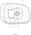
- FIG. 2C is a front view of the vehicle mirror wiping unit 100, according to some embodiments of the present disclosure.
- FIG. 3A is an exploded isometric view of the mirror mounting unit 300 of the vehicle mirror wiping unit 100, according to some embodiments of the present disclosure.
- FIG. 3B is a side view of the mirror mounting unit 300 of the vehicle mirror wiping unit 100, according to some embodiments of the present disclosure.
- FIG. 3C is an isometric rear view of the mirror mounting unit 300 of the vehicle mirror wiping unit 100, according to some embodiments of the present disclosure.
- FIG. 4 is an isometric rear view of the mirror shutter assembly 400 of the vehicle mirror wiping unit 100, according to some embodiments of the present disclosure.
- the vehicle mirror wiping unit 100 consisting of: (a) the mirror 204 as depicted in FIG. 2A ; (b) the mirror shutter assembly 400 as depicted in FIG. 4 ; (c) as depicted in FIG. 2A , the mirror casing 102 mounted with the mirror motor 210; (d) the mirror mounting unit 300 as depicted in FIGS. 3A-3C ; (e) as depicted in FIGS.
- the cleaning elastomer 312 triggered by the mirror shutter motor 208.
- the cleaning elastomer 312 along with the mirror shutter 206 moves from the first end of the mirror 204 to the second end of the mirror 204 or vice versa.
- the cleaning elastomer 312 in the mirror shutter 206 wipes the mirror 204.
- the cleaning elastomer 312 is a cleaning foam, or a cleaning sponge.
- the mirror shutter motor 208 is actuated when the mirror 204 is completely pulled back.
- the mirror shutter motor 208 is actuated in a rotary motion to pull the mirror 204 from a bottom direction to a top direction.
- a sensor (not depicted in drawings) corresponds to a position sensor for detecting a position of the mirror shutter 206.
- the position can be a bottom end or a top end of the mirror 204.
- a frontal surface of the mirror shutter (206) is a reflective surface functioning as a mirror until cleaning of the mirror (204) is completed.
- the mirror shutter assembly 400 consisting of: (i) the mirror shutter holder 202, (ii) the mirror shutter 206, and (iii) the mirror shutter motor 208.
- the mirror mounting unit 300 consisting of: (i) the mirror 204, (ii) the mirror spring 214, (iii) the spring retaining cap 216, and (iv) the mirror spring holder 212.
- the vehicle mirror wiping unit 100 can be alternatively referred as a side-view mirror wiping unit 100.
- a vehicle can be a car, a truck etc.
- a mirror of the vehicle can be a side-view mirror of a car.
- the cut-out 308 and 310 can be a hole, or a slot etc.
- the mirror 204 is integral mounted on to the mirror shaft 304.
- the mirror spring holder 212 is assembled with the mirror spring 214 and the spring retaining cap 216.
- the mirror motor 210 is connected to the mirror mounting unit 300 through the motor shaft 218.
- the motor shaft 218 passes through the hook 306.
- the mirror motor 210 is actuated in a linear motion to pull the mirror 204 from the first end to the second end or vice versa.
- the mirror spring 214 is compressed, and the pin 302 is fastened on to the mirror shaft 304 from inside of a vertical slot of the mirror spring holder 212.
- the spring retaining cap 216 is fixed fastened with a plurality of screws.
- the mirror shutter 206 is attached to the shutter spindle 402 on which the mirror shutter 206 is rolled.
- the mirror shutter 206 along with the shutter spindle 402 is mounted on a space provided in the mirror shutter holder 202.
- the mirror shutter motor 208 is mounted on the mirror shutter holder 202 and connected to the shutter spindle 402.
- the mirror shutter 206 is rolled up to the first end to cover the mirror 204 and is rolled down to the second end to uncover the mirror 204 by actuating the mirror shutter motor 208.
- the embodiments of present disclosure herein addresses unresolved problem of obstruction of a driver's view arises while cleaning the side view mirror of the vehicle.
- the embodiment thus provides the vehicle mirror wiping unit.
- the vehicle mirror wiping unit are hidden, look like a normal glass, and the driver of the vehicle can trigger the hidden wiping unit for wiping the side view mirror at any time needed.
- the vehicle mirror wiping unit is designed with combination of foam, plastic, and metal parts which are replaceable and serviceable.
- the vehicle mirror wiping unit does not obstruct view of the driver while cleaning the side view mirror.
- the design of the vehicle mirror wiping unit is compatible for cleaning any kind of fixed mirror.
- the vehicle mirror wiping unit include a linear and a rotary actuation mechanism. Entire surface of the vehicle mirror wiping unit that wipes does not block the view and include a mirror surface, hidden wiper (e.g., flap) when not in operation.
- the vehicle mirror wiping unit which moves bottom to top and retracts to bottom totally hiding itself when not in operation.
- the motor pulls whole front mirror towards back and then wiping is initiated.
- the vehicle mirror wiping unit includes one or more guideways but there are no rolling elements.
- the vehicle mirror wiping unit is of low friction material which slides in the guideways.
- the vehicle mirror wiping unit in which the wiper includes a flexible plastic roll with foam gets concealed inside body of the side view mirror when not in use, thereby no obstruction in driver's view.
- the mirror moves backward and then the mirror shutter include the mirror surface. Accordingly, the shutter is fully expandable, and view is not obstructed, or the driver's view is functional all the time.
- a frontal surface of the mirror shutter is a reflective surface functioning as a mirror until cleaning of the mirror is completed. Hence, the driver's view is unobstructed, and accidents are avoided.
- Such computer-readable storage means contain program-code means for implementation of one or more steps of the method, when the program runs on a server or mobile device or any suitable programmable device.
- the hardware device can be any kind of device which can be programmed including e.g., any kind of computer like a server or a personal computer, or the like, or any combination thereof.
- the device may also include means which could be e.g., hardware means like e.g., an applicationspecific integrated circuit (ASIC), a field-programmable gate array (FPGA), or a combination of hardware and software means, e.g., an ASIC and an FPGA, or at least one microprocessor and at least one memory with software processing components located therein.
- the means can include both hardware means and software means.
- the method embodiments described herein could be implemented in hardware and software.
- the device may also include software means. Alternatively, the embodiments may be implemented on different hardware devices, e.g., using a plurality of CPUs.
- the embodiments herein can comprise hardware and software elements.
- the embodiments that are implemented in software include but are not limited to, firmware, resident software, microcode, etc.
- the functions performed by various components described herein may be implemented in other components or combinations of other components.
- a computerusable or computer readable medium can be any apparatus that can comprise, store, communicate, propagate, or transport the program for use by or in connection with the instruction execution system, apparatus, or device.
- a computer-readable storage medium refers to any type of physical memory on which information or data readable by a processor may be stored.
- a computer-readable storage medium may store instructions for execution by one or more processors, including instructions for causing the processor(s) to perform steps or stages consistent with the embodiments described herein.
- the term "computer-readable medium” should be understood to include tangible items and exclude carrier waves and transient signals, i.e., be non-transitory. Examples include random access memory (RAM), read-only memory (ROM), volatile memory, nonvolatile memory, hard drives, CD ROMs, DVDs, flash drives, disks, and any other known physical storage media.
Landscapes
- Engineering & Computer Science (AREA)
- Mechanical Engineering (AREA)
- Multimedia (AREA)
- Rear-View Mirror Devices That Are Mounted On The Exterior Of The Vehicle (AREA)
Abstract
Description
- The present application claims priority to
Indian application, Application No. 202121040618, filed in India on September 07, 2021 - The disclosure herein generally relates to cleaning system, and, more particularly, to a vehicle mirror wiping unit.
- In transportation system, a wiper attached in a side-view mirror of a vehicle is utilized to clean dust or rain droplets settled in the side-view mirror of the vehicle like, car, truck etc. Visibility problem arises for driver of the vehicle during rainy season or in a dusty environment, which leads to an accident. At present, there are wiper attached either visibly or adjusted sideways on the side view mirror. The driver's view is obstructed when the wiper of the side view mirror is operational as there is no mirror surface available in the wiper. The mechanism of the wiper attached to the side view mirror is entirely complex. Wear and tear of the existing wipers is high. In some scenario, the wiper is mounted on one or more rollers in guideways resulting in mechanism failure due to a misalignment problem. Existing wipers are not flexible and when they collapse, still partially obstruct the driver's view leading towards distraction which is a safety aspect. There is a need for a wiper to overcome the problem of obstruction arises to the driver's view.
- Embodiments of the present disclosure present technological improvements as solutions to one or more of the above-mentioned technical problems recognized by the inventors in conventional systems. For example, in one embodiment, a vehicle mirror wiping unit is provided. The vehicle mirror wiping unit include a mirror; a mirror shutter assembly, consisting of: (i) a mirror shutter holder, (ii) a mirror shutter, and (iii) a mirror shutter motor; a mirror casing mounted with the mirror motor; a mirror mounting unit consisting of: (i) the mirror, (ii) a mirror spring, (iii) a spring retaining cap, and (iv) a mirror spring holder; a pin passing through a cut-out of the spring retaining cap, and a cut-out in the mirror spring holder; and a cleaning elastomer triggered by the mirror shutter motor, and the cleaning elastomer along with the mirror shutter moves from a first end of the mirror to a second end of the mirror. The mirror is integral mounted on to a mirror shaft. The mirror spring holder is assembled with the mirror spring and the spring retaining cap. The mirror motor is connected to the mirror mounting unit through a motor shaft. The motor shaft passes through a hook. The mirror motor is actuated in a linear motion to pull the mirror from the first end to the second end or vice versa. A frontal surface of the mirror shutter is a reflective surface functioning as a mirror.
- The mirror spring is compressed, and the pin is fastened on to the mirror shaft from inside of a vertical slot of the mirror spring holder. The spring retaining cap is fixed fastened with a plurality of screws. The mirror shutter is attached to a shutter spindle on which the mirror shutter is rolled. The mirror shutter along with the shutter spindle is mounted on a space provided in the mirror shutter holder. The mirror shutter motor is mounted on the mirror shutter holder and connected to the shutter spindle. The mirror shutter is rolled up to the first end to cover the mirror and is rolled down to the second end to uncover the mirror by actuating the mirror shutter motor. The cleaning elastomer in the mirror shutter wipes the mirror. The mirror shutter motor is actuated when the mirror is completely pulled back. The mirror shutter motor is actuated in a rotary motion to pull the mirror from a bottom direction to a top direction.
- It is to be understood that both the foregoing general description and the following detailed description are exemplary and explanatory only and are not restrictive of the invention, as claimed.
- The accompanying drawings, which are incorporated in and constitute a part of this disclosure, illustrate exemplary embodiments and, together with the description, serve to explain the disclosed principles:
-
FIG. 1 is an isometric view of a vehicle mirror wiping unit, according to some embodiments of the present disclosure. -
FIGS. 2A-2B are exploded views of the vehicle mirror wiping unit, according to some embodiments of the present disclosure. -
FIG. 2C is a front view of the vehicle mirror wiping unit, according to some embodiments of the present disclosure. -
FIG. 3A is an exploded isometric view of a mirror mounting unit of the vehicle mirror wiping unit, according to some embodiments of the present disclosure. -
FIG. 3B is a side view of the mirror mounting unit of the vehicle mirror wiping unit, according to some embodiments of the present disclosure. -
FIG. 3C is an isometric rear view of the mirror mounting unit of the vehicle mirror wiping unit, according to some embodiments of the present disclosure. -
FIG. 4 is an isometric rear view of a mirror shutter assembly of the vehicle mirror wiping unit, according to some embodiments of the present disclosure. - Exemplary embodiments are described with reference to the accompanying drawings. In the figures, the left-most digit(s) of a reference number identifies the figure in which the reference number first appears. Wherever convenient, the same reference numbers are used throughout the drawings to refer to the same or like parts. While examples and features of disclosed principles are described herein, modifications, adaptations, and other implementations are possible without departing from the scope of the disclosed embodiments.
- Embodiments of the present disclosure provide a vehicle mirror wiping unit which is hidden, inside a mirror casing. A driver of a vehicle can trigger the hidden wiping unit to show up for wiping the vehicle mirror at any time needed. The vehicle mirror wiping unit is designed in such a way to not obstruct view of the driver while cleaning the side view mirror of the vehicle. The vehicle mirror wiping unit which moves bottom to top and retracts to bottom totally hiding itself when not in operation. The motor pulls whole front mirror towards back and then starts the wiping mechanism.
- Referring now to the drawings, and more particularly to
FIGS. 1 through FIG. 4 , where similar reference characters denote corresponding features consistently throughout the figures, there are shown preferred embodiments and these embodiments are described in the context of the following exemplary system and/or method. - Reference numerals of one or more components of the vehicle mirror wiping unit, as depicted in the
FIGS. 1 through FIG. 4 are provided in Table 1 below for ease of description.TABLE 1 S.NO NAME OF COMPONENT REFERENCE NUMERALS 1 Vehicle mirror wiping unit 100 2 Mirror casing 102 3 Mirror shutter holder 202 4 Mirror 204 5 Mirror shutter 206 6 Mirror shutter motor 208 7 Mirror motor 210 8 Mirror spring holder 212 9 Mirror spring 214 10 Spring retaining cap 216 11 Motor shaft 218 12 Mirror mounting unit 300 13 Pin 302 14 Mirror shaft 304 15 Hook 306 16 Cut-out in the spring retaining cap 308 17 Cut-out in the mirror spring holder 310 18 Cleaning elastomer 312 19 Mirror shutter assembly 400 20 Shutter spindle 402 -
FIG. 1 is an isometric view of the vehiclemirror wiping unit 100, according to some embodiments of the present disclosure.FIGS. 2A-2B are exploded views of the vehiclemirror wiping unit 100, according to some embodiments of the present disclosure.FIG. 2C is a front view of the vehiclemirror wiping unit 100, according to some embodiments of the present disclosure.FIG. 3A is an exploded isometric view of themirror mounting unit 300 of the vehiclemirror wiping unit 100, according to some embodiments of the present disclosure.FIG. 3B is a side view of themirror mounting unit 300 of the vehiclemirror wiping unit 100, according to some embodiments of the present disclosure.FIG. 3C is an isometric rear view of themirror mounting unit 300 of the vehiclemirror wiping unit 100, according to some embodiments of the present disclosure.FIG. 4 is an isometric rear view of themirror shutter assembly 400 of the vehiclemirror wiping unit 100, according to some embodiments of the present disclosure. The vehiclemirror wiping unit 100 consisting of: (a) themirror 204 as depicted inFIG. 2A ;(b) themirror shutter assembly 400 as depicted inFIG. 4 ; (c) as depicted inFIG. 2A , themirror casing 102 mounted with themirror motor 210; (d) themirror mounting unit 300 as depicted inFIGS. 3A-3C ; (e) as depicted inFIGS. 3A-3C , thepin 302 passing through the cut-out 308 of thespring retaining cap 216, and the cut-out 310 in themirror spring holder 212; and (f) as depicted inFIG. 3C , the cleaningelastomer 312 triggered by themirror shutter motor 208. The cleaningelastomer 312 along with themirror shutter 206 moves from the first end of themirror 204 to the second end of themirror 204 or vice versa. The cleaningelastomer 312 in themirror shutter 206 wipes themirror 204. In an embodiment, the cleaningelastomer 312 is a cleaning foam, or a cleaning sponge. Themirror shutter motor 208 is actuated when themirror 204 is completely pulled back. Themirror shutter motor 208 is actuated in a rotary motion to pull themirror 204 from a bottom direction to a top direction. In an embodiment, a sensor (not depicted in drawings) corresponds to a position sensor for detecting a position of themirror shutter 206. For example, the position can be a bottom end or a top end of themirror 204. A frontal surface of the mirror shutter (206) is a reflective surface functioning as a mirror until cleaning of the mirror (204) is completed. - The
mirror shutter assembly 400, consisting of: (i) themirror shutter holder 202, (ii) themirror shutter 206, and (iii) themirror shutter motor 208. Themirror mounting unit 300, consisting of: (i) themirror 204, (ii) themirror spring 214, (iii) thespring retaining cap 216, and (iv) themirror spring holder 212. In an embodiment, the vehiclemirror wiping unit 100 can be alternatively referred as a side-viewmirror wiping unit 100. For example, a vehicle can be a car, a truck etc. For example, a mirror of the vehicle can be a side-view mirror of a car. In an embodiment, the cut-out 308 and 310 can be a hole, or a slot etc. - The
mirror 204 is integral mounted on to themirror shaft 304. Themirror spring holder 212 is assembled with themirror spring 214 and thespring retaining cap 216. Themirror motor 210 is connected to themirror mounting unit 300 through themotor shaft 218. Themotor shaft 218 passes through thehook 306. Themirror motor 210 is actuated in a linear motion to pull themirror 204 from the first end to the second end or vice versa. Themirror spring 214 is compressed, and thepin 302 is fastened on to themirror shaft 304 from inside of a vertical slot of themirror spring holder 212. - The
spring retaining cap 216 is fixed fastened with a plurality of screws. As depicted inFIG. 4 , themirror shutter 206 is attached to theshutter spindle 402 on which themirror shutter 206 is rolled. Themirror shutter 206 along with theshutter spindle 402 is mounted on a space provided in themirror shutter holder 202. Themirror shutter motor 208 is mounted on themirror shutter holder 202 and connected to theshutter spindle 402. Themirror shutter 206 is rolled up to the first end to cover themirror 204 and is rolled down to the second end to uncover themirror 204 by actuating themirror shutter motor 208. - The embodiments of present disclosure herein addresses unresolved problem of obstruction of a driver's view arises while cleaning the side view mirror of the vehicle. The embodiment thus provides the vehicle mirror wiping unit. The vehicle mirror wiping unit are hidden, look like a normal glass, and the driver of the vehicle can trigger the hidden wiping unit for wiping the side view mirror at any time needed. The vehicle mirror wiping unit is designed with combination of foam, plastic, and metal parts which are replaceable and serviceable. The vehicle mirror wiping unit does not obstruct view of the driver while cleaning the side view mirror. The design of the vehicle mirror wiping unit is compatible for cleaning any kind of fixed mirror. The vehicle mirror wiping unit include a linear and a rotary actuation mechanism. Entire surface of the vehicle mirror wiping unit that wipes does not block the view and include a mirror surface, hidden wiper (e.g., flap) when not in operation.
- The vehicle mirror wiping unit which moves bottom to top and retracts to bottom totally hiding itself when not in operation. The motor pulls whole front mirror towards back and then wiping is initiated. The vehicle mirror wiping unit includes one or more guideways but there are no rolling elements. The vehicle mirror wiping unit is of low friction material which slides in the guideways. The vehicle mirror wiping unit in which the wiper includes a flexible plastic roll with foam gets concealed inside body of the side view mirror when not in use, thereby no obstruction in driver's view. The mirror moves backward and then the mirror shutter include the mirror surface. Accordingly, the shutter is fully expandable, and view is not obstructed, or the driver's view is functional all the time. A frontal surface of the mirror shutter is a reflective surface functioning as a mirror until cleaning of the mirror is completed. Hence, the driver's view is unobstructed, and accidents are avoided.
- The written description describes the subject matter herein to enable any person skilled in the art to make and use the embodiments. The scope of the subject matter embodiments is defined by the claims and may include other modifications that occur to those skilled in the art. Such other modifications are intended to be within the scope of the claims if they have similar elements that do not differ from the literal language of the claims or if they include equivalent elements with insubstantial differences from the literal language of the claims.
- It is to be understood that the scope of the protection is extended to such a program and in addition to a computer-readable means having a message therein; such computer-readable storage means contain program-code means for implementation of one or more steps of the method, when the program runs on a server or mobile device or any suitable programmable device. The hardware device can be any kind of device which can be programmed including e.g., any kind of computer like a server or a personal computer, or the like, or any combination thereof. The device may also include means which could be e.g., hardware means like e.g., an applicationspecific integrated circuit (ASIC), a field-programmable gate array (FPGA), or a combination of hardware and software means, e.g., an ASIC and an FPGA, or at least one microprocessor and at least one memory with software processing components located therein. Thus, the means can include both hardware means and software means. The method embodiments described herein could be implemented in hardware and software. The device may also include software means. Alternatively, the embodiments may be implemented on different hardware devices, e.g., using a plurality of CPUs.
- The embodiments herein can comprise hardware and software elements. The embodiments that are implemented in software include but are not limited to, firmware, resident software, microcode, etc. The functions performed by various components described herein may be implemented in other components or combinations of other components. For the purposes of this description, a computerusable or computer readable medium can be any apparatus that can comprise, store, communicate, propagate, or transport the program for use by or in connection with the instruction execution system, apparatus, or device.
- The illustrated steps are set out to explain the exemplary embodiments shown, and it should be anticipated that ongoing technological development will change the manner in which particular functions are performed. These examples are presented herein for purposes of illustration, and not limitation. Further, the boundaries of the functional building blocks have been arbitrarily defined herein for the convenience of the description. Alternative boundaries can be defined so long as the specified functions and relationships thereof are appropriately performed. Alternatives (including equivalents, extensions, variations, deviations, etc., of those described herein) will be apparent to persons skilled in the relevant art(s) based on the teachings contained herein. Such alternatives fall within the scope of the disclosed embodiments. Also, the words "comprising," "having," "containing," and "including," and other similar forms are intended to be equivalent in meaning and be open ended in that an item or items following any one of these words is not meant to be an exhaustive listing of such item or items, or meant to be limited to only the listed item or items. It must also be noted that as used herein and in the appended claims, the singular forms "a," "an," and "the" include plural references unless the context clearly dictates otherwise.
- Furthermore, one or more computer-readable storage media may be utilized in implementing embodiments consistent with the present disclosure. A computer-readable storage medium refers to any type of physical memory on which information or data readable by a processor may be stored. Thus, a computer-readable storage medium may store instructions for execution by one or more processors, including instructions for causing the processor(s) to perform steps or stages consistent with the embodiments described herein. The term "computer-readable medium" should be understood to include tangible items and exclude carrier waves and transient signals, i.e., be non-transitory. Examples include random access memory (RAM), read-only memory (ROM), volatile memory, nonvolatile memory, hard drives, CD ROMs, DVDs, flash drives, disks, and any other known physical storage media.
- It is intended that the disclosure and examples be considered as exemplary only, with a true scope of disclosed embodiments being indicated by the following claims.
Claims (10)
- A vehicle mirror wiping unit (100), comprising:a mirror (204), wherein the mirror (204) is integral mounted on to a mirror shaft (304);a mirror shutter assembly (400), consisting of: (i) a mirror shutter holder (202), (ii) a mirror shutter (206), and (iii) a mirror shutter motor (208);a mirror casing (102) mounted with the mirror motor (210);a mirror mounting unit (300), consisting of: (i) the mirror (204), (ii) a mirror spring (214), (iii) a spring retaining cap (216), and (iv) a mirror spring holder (212), wherein the mirror spring holder (212) is assembled with the mirror spring (214) and the spring retaining cap (216);a pin (302) passing through a cut-out (308) of the spring retaining cap (216), and a cut-out (310) in the mirror spring holder (212), wherein the mirror motor (210) is connected to the mirror mounting unit (300) through a motor shaft (218), wherein the motor shaft (218) passes through a hook (306), and wherein the mirror motor (210) is actuated in a linear motion to pull the mirror (204) from a first end to a second end or vice versa; anda cleaning elastomer (312) triggered by the mirror shutter motor (208), wherein the cleaning elastomer (312) along with the mirror shutter (206) moves from the first end of the mirror (204) to the second end of the mirror (204), wherein a frontal surface of the mirror shutter (206) is a reflective surface functioning as a mirror.
- The vehicle mirror wiping unit (100) as claimed in claim 1, wherein the mirror spring (214) is compressed, and the pin (302) is fastened on to the mirror shaft (304) from inside of a vertical slot of the mirror spring holder (212).
- The vehicle mirror wiping unit (100) as claimed in claim 1, wherein the spring retaining cap (216) is fixed fastened with a plurality of screws.
- The vehicle mirror wiping unit (100) as claimed in claim 1, wherein the mirror shutter (206) is attached to a shutter spindle (402) on which the mirror shutter (206) is rolled.
- The vehicle mirror wiping unit (100) as claimed in claim 4, wherein the mirror shutter (206) along with the shutter spindle (402) is mounted on a space provided in the mirror shutter holder (202).
- The vehicle mirror wiping unit (100) as claimed in claim 1, wherein the mirror shutter motor (208) is mounted on the mirror shutter holder (202) and connected to the shutter spindle (402).
- The vehicle mirror wiping unit (100) as claimed in claim 1, wherein the mirror shutter (206) is rolled up to the first end to cover the mirror (204) and is rolled down to the second end to uncover the mirror (204) by actuating the mirror shutter motor (208).
- The vehicle mirror wiping unit (100) as claimed in claim 1, wherein the cleaning elastomer (312) in the mirror shutter (206) wipes the mirror (204).
- The vehicle mirror wiping unit (100) as claimed in claim 1, wherein the mirror shutter motor (208) is actuated when the mirror (204) is completely pulled back.
- The vehicle mirror wiping unit (100) as claimed in claim 1, wherein the mirror shutter motor (208) is actuated in a rotary motion to pull the mirror (204) from a bottom direction to a top direction.
Applications Claiming Priority (1)
| Application Number | Priority Date | Filing Date | Title |
|---|---|---|---|
| IN202121040618 | 2021-09-07 |
Publications (3)
| Publication Number | Publication Date |
|---|---|
| EP4144586A1 true EP4144586A1 (en) | 2023-03-08 |
| EP4144586C0 EP4144586C0 (en) | 2024-03-13 |
| EP4144586B1 EP4144586B1 (en) | 2024-03-13 |
Family
ID=83006054
Family Applications (1)
| Application Number | Title | Priority Date | Filing Date |
|---|---|---|---|
| EP22191427.8A Active EP4144586B1 (en) | 2021-09-07 | 2022-08-22 | Vehicle mirror wiping unit |
Country Status (2)
| Country | Link |
|---|---|
| US (1) | US11904774B2 (en) |
| EP (1) | EP4144586B1 (en) |
Citations (2)
| Publication number | Priority date | Publication date | Assignee | Title |
|---|---|---|---|---|
| KR20010065964A (en) * | 1999-12-30 | 2001-07-11 | 이계안 | Rear view mirror for automobile |
| GB2360444A (en) * | 2000-03-22 | 2001-09-26 | Freight Ltd J | Mirror clearing means |
Family Cites Families (6)
| Publication number | Priority date | Publication date | Assignee | Title |
|---|---|---|---|---|
| JPS61215143A (en) | 1985-03-20 | 1986-09-24 | Sakurai Kk | Antifouling device for car mirror |
| JPH01161160U (en) * | 1988-04-30 | 1989-11-09 | ||
| US6546590B2 (en) | 2001-01-31 | 2003-04-15 | Gary Waters | Automatic attachable side-view mirror cleaning device |
| US6691365B2 (en) | 2001-09-04 | 2004-02-17 | Eric C. Graf | Side mirror wiper |
| WO2005019006A1 (en) | 2003-08-20 | 2005-03-03 | Je Don Kim | Automatic apparatus for removing raindrops and mist on automobile side mirror |
| CN106240469A (en) | 2016-08-03 | 2016-12-21 | 林婉骞 | A kind of Novel rearview optical module of automobile-use |
-
2022
- 2022-08-22 EP EP22191427.8A patent/EP4144586B1/en active Active
- 2022-08-23 US US17/893,237 patent/US11904774B2/en active Active
Patent Citations (2)
| Publication number | Priority date | Publication date | Assignee | Title |
|---|---|---|---|---|
| KR20010065964A (en) * | 1999-12-30 | 2001-07-11 | 이계안 | Rear view mirror for automobile |
| GB2360444A (en) * | 2000-03-22 | 2001-09-26 | Freight Ltd J | Mirror clearing means |
Also Published As
| Publication number | Publication date |
|---|---|
| US20230105928A1 (en) | 2023-04-06 |
| EP4144586C0 (en) | 2024-03-13 |
| US11904774B2 (en) | 2024-02-20 |
| EP4144586B1 (en) | 2024-03-13 |
Similar Documents
| Publication | Publication Date | Title |
|---|---|---|
| KR102501632B1 (en) | rotary wiper system | |
| US5657810A (en) | Screening device for vehicle windows | |
| EP1859993A1 (en) | Vehicle monitor apparatus | |
| US10562466B2 (en) | Side imaging device for vehicle | |
| EP1997996B1 (en) | Pinch prevention of slide device | |
| US6834705B2 (en) | Window roller blind or partition net with two angular gears | |
| JP2007500096A (en) | Automotive rear view device | |
| JP7662551B2 (en) | Vehicle display device | |
| US10632926B2 (en) | Vehicle sensor system | |
| EP4144586B1 (en) | Vehicle mirror wiping unit | |
| CN110116709A (en) | Sensors clean device | |
| KR101551094B1 (en) | Panelless cargo screen and vehicle having the same | |
| US6231105B1 (en) | Sun visor for vehicle | |
| US20240351407A1 (en) | Motorized Windshield Shade Device | |
| EP3744568B1 (en) | A system and method for providing a desired view for a vehicle occupant | |
| US20190077380A1 (en) | Vehicle sensor system | |
| US7393028B2 (en) | Device for storing article for protecting automobile body | |
| JP2009220651A (en) | Front pillar structure of vehicle | |
| EP1253047B1 (en) | Electronic equipment with retractable display | |
| CN116330946A (en) | Weather strip for vehicle | |
| US20060056657A1 (en) | Single image sensor positioning method and apparatus in a multiple function vehicle protection control system | |
| KR102910406B1 (en) | Monitoring apparatus for vehicle | |
| JPH10166947A (en) | rearview mirror | |
| KR100551795B1 (en) | Outside mirror folding device | |
| JP2009083708A (en) | On-vehicle panel device |
Legal Events
| Date | Code | Title | Description |
|---|---|---|---|
| PUAI | Public reference made under article 153(3) epc to a published international application that has entered the european phase |
Free format text: ORIGINAL CODE: 0009012 |
|
| STAA | Information on the status of an ep patent application or granted ep patent |
Free format text: STATUS: REQUEST FOR EXAMINATION WAS MADE |
|
| 17P | Request for examination filed |
Effective date: 20230130 |
|
| AK | Designated contracting states |
Kind code of ref document: A1 Designated state(s): AL AT BE BG CH CY CZ DE DK EE ES FI FR GB GR HR HU IE IS IT LI LT LU LV MC MK MT NL NO PL PT RO RS SE SI SK SM TR |
|
| GRAP | Despatch of communication of intention to grant a patent |
Free format text: ORIGINAL CODE: EPIDOSNIGR1 |
|
| STAA | Information on the status of an ep patent application or granted ep patent |
Free format text: STATUS: GRANT OF PATENT IS INTENDED |
|
| INTG | Intention to grant announced |
Effective date: 20230908 |
|
| GRAS | Grant fee paid |
Free format text: ORIGINAL CODE: EPIDOSNIGR3 |
|
| GRAA | (expected) grant |
Free format text: ORIGINAL CODE: 0009210 |
|
| STAA | Information on the status of an ep patent application or granted ep patent |
Free format text: STATUS: THE PATENT HAS BEEN GRANTED |
|
| AK | Designated contracting states |
Kind code of ref document: B1 Designated state(s): AL AT BE BG CH CY CZ DE DK EE ES FI FR GB GR HR HU IE IS IT LI LT LU LV MC MK MT NL NO PL PT RO RS SE SI SK SM TR |
|
| REG | Reference to a national code |
Ref country code: GB Ref legal event code: FG4D |
|
| REG | Reference to a national code |
Ref country code: CH Ref legal event code: EP |
|
| REG | Reference to a national code |
Ref country code: DE Ref legal event code: R096 Ref document number: 602022002350 Country of ref document: DE |
|
| REG | Reference to a national code |
Ref country code: IE Ref legal event code: FG4D |
|
| U01 | Request for unitary effect filed |
Effective date: 20240313 |
|
| U07 | Unitary effect registered |
Designated state(s): AT BE BG DE DK EE FI FR IT LT LU LV MT NL PT SE SI Effective date: 20240321 |
|
| PG25 | Lapsed in a contracting state [announced via postgrant information from national office to epo] |
Ref country code: GR Free format text: LAPSE BECAUSE OF FAILURE TO SUBMIT A TRANSLATION OF THE DESCRIPTION OR TO PAY THE FEE WITHIN THE PRESCRIBED TIME-LIMIT Effective date: 20240614 |
|
| PG25 | Lapsed in a contracting state [announced via postgrant information from national office to epo] |
Ref country code: HR Free format text: LAPSE BECAUSE OF FAILURE TO SUBMIT A TRANSLATION OF THE DESCRIPTION OR TO PAY THE FEE WITHIN THE PRESCRIBED TIME-LIMIT Effective date: 20240313 Ref country code: RS Free format text: LAPSE BECAUSE OF FAILURE TO SUBMIT A TRANSLATION OF THE DESCRIPTION OR TO PAY THE FEE WITHIN THE PRESCRIBED TIME-LIMIT Effective date: 20240613 |
|
| PG25 | Lapsed in a contracting state [announced via postgrant information from national office to epo] |
Ref country code: ES Free format text: LAPSE BECAUSE OF FAILURE TO SUBMIT A TRANSLATION OF THE DESCRIPTION OR TO PAY THE FEE WITHIN THE PRESCRIBED TIME-LIMIT Effective date: 20240313 |
|
| PG25 | Lapsed in a contracting state [announced via postgrant information from national office to epo] |
Ref country code: RS Free format text: LAPSE BECAUSE OF FAILURE TO SUBMIT A TRANSLATION OF THE DESCRIPTION OR TO PAY THE FEE WITHIN THE PRESCRIBED TIME-LIMIT Effective date: 20240613 Ref country code: NO Free format text: LAPSE BECAUSE OF FAILURE TO SUBMIT A TRANSLATION OF THE DESCRIPTION OR TO PAY THE FEE WITHIN THE PRESCRIBED TIME-LIMIT Effective date: 20240613 Ref country code: HR Free format text: LAPSE BECAUSE OF FAILURE TO SUBMIT A TRANSLATION OF THE DESCRIPTION OR TO PAY THE FEE WITHIN THE PRESCRIBED TIME-LIMIT Effective date: 20240313 Ref country code: GR Free format text: LAPSE BECAUSE OF FAILURE TO SUBMIT A TRANSLATION OF THE DESCRIPTION OR TO PAY THE FEE WITHIN THE PRESCRIBED TIME-LIMIT Effective date: 20240614 Ref country code: ES Free format text: LAPSE BECAUSE OF FAILURE TO SUBMIT A TRANSLATION OF THE DESCRIPTION OR TO PAY THE FEE WITHIN THE PRESCRIBED TIME-LIMIT Effective date: 20240313 |
|
| U20 | Renewal fee for the european patent with unitary effect paid |
Year of fee payment: 3 Effective date: 20240826 |
|
| PG25 | Lapsed in a contracting state [announced via postgrant information from national office to epo] |
Ref country code: IS Free format text: LAPSE BECAUSE OF FAILURE TO SUBMIT A TRANSLATION OF THE DESCRIPTION OR TO PAY THE FEE WITHIN THE PRESCRIBED TIME-LIMIT Effective date: 20240713 |
|
| PG25 | Lapsed in a contracting state [announced via postgrant information from national office to epo] |
Ref country code: SM Free format text: LAPSE BECAUSE OF FAILURE TO SUBMIT A TRANSLATION OF THE DESCRIPTION OR TO PAY THE FEE WITHIN THE PRESCRIBED TIME-LIMIT Effective date: 20240313 |
|
| PG25 | Lapsed in a contracting state [announced via postgrant information from national office to epo] |
Ref country code: CZ Free format text: LAPSE BECAUSE OF FAILURE TO SUBMIT A TRANSLATION OF THE DESCRIPTION OR TO PAY THE FEE WITHIN THE PRESCRIBED TIME-LIMIT Effective date: 20240313 |
|
| PG25 | Lapsed in a contracting state [announced via postgrant information from national office to epo] |
Ref country code: PL Free format text: LAPSE BECAUSE OF FAILURE TO SUBMIT A TRANSLATION OF THE DESCRIPTION OR TO PAY THE FEE WITHIN THE PRESCRIBED TIME-LIMIT Effective date: 20240313 |
|
| PG25 | Lapsed in a contracting state [announced via postgrant information from national office to epo] |
Ref country code: SK Free format text: LAPSE BECAUSE OF FAILURE TO SUBMIT A TRANSLATION OF THE DESCRIPTION OR TO PAY THE FEE WITHIN THE PRESCRIBED TIME-LIMIT Effective date: 20240313 |
|
| PG25 | Lapsed in a contracting state [announced via postgrant information from national office to epo] |
Ref country code: SM Free format text: LAPSE BECAUSE OF FAILURE TO SUBMIT A TRANSLATION OF THE DESCRIPTION OR TO PAY THE FEE WITHIN THE PRESCRIBED TIME-LIMIT Effective date: 20240313 Ref country code: SK Free format text: LAPSE BECAUSE OF FAILURE TO SUBMIT A TRANSLATION OF THE DESCRIPTION OR TO PAY THE FEE WITHIN THE PRESCRIBED TIME-LIMIT Effective date: 20240313 Ref country code: RO Free format text: LAPSE BECAUSE OF FAILURE TO SUBMIT A TRANSLATION OF THE DESCRIPTION OR TO PAY THE FEE WITHIN THE PRESCRIBED TIME-LIMIT Effective date: 20240313 Ref country code: PL Free format text: LAPSE BECAUSE OF FAILURE TO SUBMIT A TRANSLATION OF THE DESCRIPTION OR TO PAY THE FEE WITHIN THE PRESCRIBED TIME-LIMIT Effective date: 20240313 Ref country code: IS Free format text: LAPSE BECAUSE OF FAILURE TO SUBMIT A TRANSLATION OF THE DESCRIPTION OR TO PAY THE FEE WITHIN THE PRESCRIBED TIME-LIMIT Effective date: 20240713 Ref country code: CZ Free format text: LAPSE BECAUSE OF FAILURE TO SUBMIT A TRANSLATION OF THE DESCRIPTION OR TO PAY THE FEE WITHIN THE PRESCRIBED TIME-LIMIT Effective date: 20240313 |
|
| REG | Reference to a national code |
Ref country code: DE Ref legal event code: R097 Ref document number: 602022002350 Country of ref document: DE |
|
| PLBE | No opposition filed within time limit |
Free format text: ORIGINAL CODE: 0009261 |
|
| STAA | Information on the status of an ep patent application or granted ep patent |
Free format text: STATUS: NO OPPOSITION FILED WITHIN TIME LIMIT |
|
| 26N | No opposition filed |
Effective date: 20241216 |
|
| PG25 | Lapsed in a contracting state [announced via postgrant information from national office to epo] |
Ref country code: MC Free format text: LAPSE BECAUSE OF FAILURE TO SUBMIT A TRANSLATION OF THE DESCRIPTION OR TO PAY THE FEE WITHIN THE PRESCRIBED TIME-LIMIT Effective date: 20240313 |
|
| PG25 | Lapsed in a contracting state [announced via postgrant information from national office to epo] |
Ref country code: IE Free format text: LAPSE BECAUSE OF NON-PAYMENT OF DUE FEES Effective date: 20240822 |
|
| U20 | Renewal fee for the european patent with unitary effect paid |
Year of fee payment: 4 Effective date: 20250825 |
|
| PGFP | Annual fee paid to national office [announced via postgrant information from national office to epo] |
Ref country code: CH Payment date: 20250901 Year of fee payment: 4 |
|
| PG25 | Lapsed in a contracting state [announced via postgrant information from national office to epo] |
Ref country code: CY Free format text: LAPSE BECAUSE OF FAILURE TO SUBMIT A TRANSLATION OF THE DESCRIPTION OR TO PAY THE FEE WITHIN THE PRESCRIBED TIME-LIMIT; INVALID AB INITIO Effective date: 20220822 |
|
| PG25 | Lapsed in a contracting state [announced via postgrant information from national office to epo] |
Ref country code: HU Free format text: LAPSE BECAUSE OF FAILURE TO SUBMIT A TRANSLATION OF THE DESCRIPTION OR TO PAY THE FEE WITHIN THE PRESCRIBED TIME-LIMIT; INVALID AB INITIO Effective date: 20220822 |