EP4144554A1 - Traction assembly for a vehicle - Google Patents
Traction assembly for a vehicle Download PDFInfo
- Publication number
- EP4144554A1 EP4144554A1 EP22193192.6A EP22193192A EP4144554A1 EP 4144554 A1 EP4144554 A1 EP 4144554A1 EP 22193192 A EP22193192 A EP 22193192A EP 4144554 A1 EP4144554 A1 EP 4144554A1
- Authority
- EP
- European Patent Office
- Prior art keywords
- shaft
- toothing
- transmission
- differential
- assembly according
- Prior art date
- Legal status (The legal status is an assumption and is not a legal conclusion. Google has not performed a legal analysis and makes no representation as to the accuracy of the status listed.)
- Pending
Links
Images


Classifications
-
- B—PERFORMING OPERATIONS; TRANSPORTING
- B60—VEHICLES IN GENERAL
- B60K—ARRANGEMENT OR MOUNTING OF PROPULSION UNITS OR OF TRANSMISSIONS IN VEHICLES; ARRANGEMENT OR MOUNTING OF PLURAL DIVERSE PRIME-MOVERS IN VEHICLES; AUXILIARY DRIVES FOR VEHICLES; INSTRUMENTATION OR DASHBOARDS FOR VEHICLES; ARRANGEMENTS IN CONNECTION WITH COOLING, AIR INTAKE, GAS EXHAUST OR FUEL SUPPLY OF PROPULSION UNITS IN VEHICLES
- B60K17/00—Arrangement or mounting of transmissions in vehicles
- B60K17/34—Arrangement or mounting of transmissions in vehicles for driving both front and rear wheels, e.g. four wheel drive vehicles
- B60K17/344—Arrangement or mounting of transmissions in vehicles for driving both front and rear wheels, e.g. four wheel drive vehicles having a transfer gear
- B60K17/346—Arrangement or mounting of transmissions in vehicles for driving both front and rear wheels, e.g. four wheel drive vehicles having a transfer gear the transfer gear being a differential gear
-
- B—PERFORMING OPERATIONS; TRANSPORTING
- B60—VEHICLES IN GENERAL
- B60K—ARRANGEMENT OR MOUNTING OF PROPULSION UNITS OR OF TRANSMISSIONS IN VEHICLES; ARRANGEMENT OR MOUNTING OF PLURAL DIVERSE PRIME-MOVERS IN VEHICLES; AUXILIARY DRIVES FOR VEHICLES; INSTRUMENTATION OR DASHBOARDS FOR VEHICLES; ARRANGEMENTS IN CONNECTION WITH COOLING, AIR INTAKE, GAS EXHAUST OR FUEL SUPPLY OF PROPULSION UNITS IN VEHICLES
- B60K6/00—Arrangement or mounting of plural diverse prime-movers for mutual or common propulsion, e.g. hybrid propulsion systems comprising electric motors and internal combustion engines
- B60K6/20—Arrangement or mounting of plural diverse prime-movers for mutual or common propulsion, e.g. hybrid propulsion systems comprising electric motors and internal combustion engines the prime-movers consisting of electric motors and internal combustion engines, e.g. HEVs
- B60K6/22—Arrangement or mounting of plural diverse prime-movers for mutual or common propulsion, e.g. hybrid propulsion systems comprising electric motors and internal combustion engines the prime-movers consisting of electric motors and internal combustion engines, e.g. HEVs characterised by apparatus, components or means specially adapted for HEVs
- B60K6/36—Arrangement or mounting of plural diverse prime-movers for mutual or common propulsion, e.g. hybrid propulsion systems comprising electric motors and internal combustion engines the prime-movers consisting of electric motors and internal combustion engines, e.g. HEVs characterised by apparatus, components or means specially adapted for HEVs characterised by the transmission gearings
-
- B—PERFORMING OPERATIONS; TRANSPORTING
- B60—VEHICLES IN GENERAL
- B60K—ARRANGEMENT OR MOUNTING OF PROPULSION UNITS OR OF TRANSMISSIONS IN VEHICLES; ARRANGEMENT OR MOUNTING OF PLURAL DIVERSE PRIME-MOVERS IN VEHICLES; AUXILIARY DRIVES FOR VEHICLES; INSTRUMENTATION OR DASHBOARDS FOR VEHICLES; ARRANGEMENTS IN CONNECTION WITH COOLING, AIR INTAKE, GAS EXHAUST OR FUEL SUPPLY OF PROPULSION UNITS IN VEHICLES
- B60K6/00—Arrangement or mounting of plural diverse prime-movers for mutual or common propulsion, e.g. hybrid propulsion systems comprising electric motors and internal combustion engines
- B60K6/20—Arrangement or mounting of plural diverse prime-movers for mutual or common propulsion, e.g. hybrid propulsion systems comprising electric motors and internal combustion engines the prime-movers consisting of electric motors and internal combustion engines, e.g. HEVs
- B60K6/22—Arrangement or mounting of plural diverse prime-movers for mutual or common propulsion, e.g. hybrid propulsion systems comprising electric motors and internal combustion engines the prime-movers consisting of electric motors and internal combustion engines, e.g. HEVs characterised by apparatus, components or means specially adapted for HEVs
- B60K6/38—Arrangement or mounting of plural diverse prime-movers for mutual or common propulsion, e.g. hybrid propulsion systems comprising electric motors and internal combustion engines the prime-movers consisting of electric motors and internal combustion engines, e.g. HEVs characterised by apparatus, components or means specially adapted for HEVs characterised by the driveline clutches
- B60K6/387—Actuated clutches, i.e. clutches engaged or disengaged by electric, hydraulic or mechanical actuating means
-
- B—PERFORMING OPERATIONS; TRANSPORTING
- B60—VEHICLES IN GENERAL
- B60K—ARRANGEMENT OR MOUNTING OF PROPULSION UNITS OR OF TRANSMISSIONS IN VEHICLES; ARRANGEMENT OR MOUNTING OF PLURAL DIVERSE PRIME-MOVERS IN VEHICLES; AUXILIARY DRIVES FOR VEHICLES; INSTRUMENTATION OR DASHBOARDS FOR VEHICLES; ARRANGEMENTS IN CONNECTION WITH COOLING, AIR INTAKE, GAS EXHAUST OR FUEL SUPPLY OF PROPULSION UNITS IN VEHICLES
- B60K6/00—Arrangement or mounting of plural diverse prime-movers for mutual or common propulsion, e.g. hybrid propulsion systems comprising electric motors and internal combustion engines
- B60K6/20—Arrangement or mounting of plural diverse prime-movers for mutual or common propulsion, e.g. hybrid propulsion systems comprising electric motors and internal combustion engines the prime-movers consisting of electric motors and internal combustion engines, e.g. HEVs
- B60K6/22—Arrangement or mounting of plural diverse prime-movers for mutual or common propulsion, e.g. hybrid propulsion systems comprising electric motors and internal combustion engines the prime-movers consisting of electric motors and internal combustion engines, e.g. HEVs characterised by apparatus, components or means specially adapted for HEVs
- B60K6/40—Arrangement or mounting of plural diverse prime-movers for mutual or common propulsion, e.g. hybrid propulsion systems comprising electric motors and internal combustion engines the prime-movers consisting of electric motors and internal combustion engines, e.g. HEVs characterised by apparatus, components or means specially adapted for HEVs characterised by the assembly or relative disposition of components
- B60K6/405—Housings
-
- B—PERFORMING OPERATIONS; TRANSPORTING
- B60—VEHICLES IN GENERAL
- B60K—ARRANGEMENT OR MOUNTING OF PROPULSION UNITS OR OF TRANSMISSIONS IN VEHICLES; ARRANGEMENT OR MOUNTING OF PLURAL DIVERSE PRIME-MOVERS IN VEHICLES; AUXILIARY DRIVES FOR VEHICLES; INSTRUMENTATION OR DASHBOARDS FOR VEHICLES; ARRANGEMENTS IN CONNECTION WITH COOLING, AIR INTAKE, GAS EXHAUST OR FUEL SUPPLY OF PROPULSION UNITS IN VEHICLES
- B60K6/00—Arrangement or mounting of plural diverse prime-movers for mutual or common propulsion, e.g. hybrid propulsion systems comprising electric motors and internal combustion engines
- B60K6/20—Arrangement or mounting of plural diverse prime-movers for mutual or common propulsion, e.g. hybrid propulsion systems comprising electric motors and internal combustion engines the prime-movers consisting of electric motors and internal combustion engines, e.g. HEVs
- B60K6/42—Arrangement or mounting of plural diverse prime-movers for mutual or common propulsion, e.g. hybrid propulsion systems comprising electric motors and internal combustion engines the prime-movers consisting of electric motors and internal combustion engines, e.g. HEVs characterised by the architecture of the hybrid electric vehicle
- B60K6/48—Parallel type
-
- B—PERFORMING OPERATIONS; TRANSPORTING
- B60—VEHICLES IN GENERAL
- B60K—ARRANGEMENT OR MOUNTING OF PROPULSION UNITS OR OF TRANSMISSIONS IN VEHICLES; ARRANGEMENT OR MOUNTING OF PLURAL DIVERSE PRIME-MOVERS IN VEHICLES; AUXILIARY DRIVES FOR VEHICLES; INSTRUMENTATION OR DASHBOARDS FOR VEHICLES; ARRANGEMENTS IN CONNECTION WITH COOLING, AIR INTAKE, GAS EXHAUST OR FUEL SUPPLY OF PROPULSION UNITS IN VEHICLES
- B60K6/00—Arrangement or mounting of plural diverse prime-movers for mutual or common propulsion, e.g. hybrid propulsion systems comprising electric motors and internal combustion engines
- B60K6/20—Arrangement or mounting of plural diverse prime-movers for mutual or common propulsion, e.g. hybrid propulsion systems comprising electric motors and internal combustion engines the prime-movers consisting of electric motors and internal combustion engines, e.g. HEVs
- B60K6/50—Architecture of the driveline characterised by arrangement or kind of transmission units
- B60K6/52—Driving a plurality of drive axles, e.g. four-wheel drive
-
- B—PERFORMING OPERATIONS; TRANSPORTING
- B60—VEHICLES IN GENERAL
- B60K—ARRANGEMENT OR MOUNTING OF PROPULSION UNITS OR OF TRANSMISSIONS IN VEHICLES; ARRANGEMENT OR MOUNTING OF PLURAL DIVERSE PRIME-MOVERS IN VEHICLES; AUXILIARY DRIVES FOR VEHICLES; INSTRUMENTATION OR DASHBOARDS FOR VEHICLES; ARRANGEMENTS IN CONNECTION WITH COOLING, AIR INTAKE, GAS EXHAUST OR FUEL SUPPLY OF PROPULSION UNITS IN VEHICLES
- B60K6/00—Arrangement or mounting of plural diverse prime-movers for mutual or common propulsion, e.g. hybrid propulsion systems comprising electric motors and internal combustion engines
- B60K6/20—Arrangement or mounting of plural diverse prime-movers for mutual or common propulsion, e.g. hybrid propulsion systems comprising electric motors and internal combustion engines the prime-movers consisting of electric motors and internal combustion engines, e.g. HEVs
- B60K6/42—Arrangement or mounting of plural diverse prime-movers for mutual or common propulsion, e.g. hybrid propulsion systems comprising electric motors and internal combustion engines the prime-movers consisting of electric motors and internal combustion engines, e.g. HEVs characterised by the architecture of the hybrid electric vehicle
- B60K6/48—Parallel type
- B60K2006/4808—Electric machine connected or connectable to gearbox output shaft
-
- B—PERFORMING OPERATIONS; TRANSPORTING
- B60—VEHICLES IN GENERAL
- B60K—ARRANGEMENT OR MOUNTING OF PROPULSION UNITS OR OF TRANSMISSIONS IN VEHICLES; ARRANGEMENT OR MOUNTING OF PLURAL DIVERSE PRIME-MOVERS IN VEHICLES; AUXILIARY DRIVES FOR VEHICLES; INSTRUMENTATION OR DASHBOARDS FOR VEHICLES; ARRANGEMENTS IN CONNECTION WITH COOLING, AIR INTAKE, GAS EXHAUST OR FUEL SUPPLY OF PROPULSION UNITS IN VEHICLES
- B60K6/00—Arrangement or mounting of plural diverse prime-movers for mutual or common propulsion, e.g. hybrid propulsion systems comprising electric motors and internal combustion engines
- B60K6/20—Arrangement or mounting of plural diverse prime-movers for mutual or common propulsion, e.g. hybrid propulsion systems comprising electric motors and internal combustion engines the prime-movers consisting of electric motors and internal combustion engines, e.g. HEVs
- B60K6/42—Arrangement or mounting of plural diverse prime-movers for mutual or common propulsion, e.g. hybrid propulsion systems comprising electric motors and internal combustion engines the prime-movers consisting of electric motors and internal combustion engines, e.g. HEVs characterised by the architecture of the hybrid electric vehicle
- B60K6/48—Parallel type
- B60K2006/4833—Step up or reduction gearing driving generator, e.g. to operate generator in most efficient speed range
- B60K2006/4841—Step up or reduction gearing driving generator, e.g. to operate generator in most efficient speed range the gear provides shifting between multiple ratios
-
- B—PERFORMING OPERATIONS; TRANSPORTING
- B60—VEHICLES IN GENERAL
- B60K—ARRANGEMENT OR MOUNTING OF PROPULSION UNITS OR OF TRANSMISSIONS IN VEHICLES; ARRANGEMENT OR MOUNTING OF PLURAL DIVERSE PRIME-MOVERS IN VEHICLES; AUXILIARY DRIVES FOR VEHICLES; INSTRUMENTATION OR DASHBOARDS FOR VEHICLES; ARRANGEMENTS IN CONNECTION WITH COOLING, AIR INTAKE, GAS EXHAUST OR FUEL SUPPLY OF PROPULSION UNITS IN VEHICLES
- B60K6/00—Arrangement or mounting of plural diverse prime-movers for mutual or common propulsion, e.g. hybrid propulsion systems comprising electric motors and internal combustion engines
- B60K6/20—Arrangement or mounting of plural diverse prime-movers for mutual or common propulsion, e.g. hybrid propulsion systems comprising electric motors and internal combustion engines the prime-movers consisting of electric motors and internal combustion engines, e.g. HEVs
- B60K6/50—Architecture of the driveline characterised by arrangement or kind of transmission units
- B60K6/54—Transmission for changing ratio
- B60K2006/542—Transmission for changing ratio with overdrive ratio
-
- B—PERFORMING OPERATIONS; TRANSPORTING
- B60—VEHICLES IN GENERAL
- B60Y—INDEXING SCHEME RELATING TO ASPECTS CROSS-CUTTING VEHICLE TECHNOLOGY
- B60Y2200/00—Type of vehicle
- B60Y2200/10—Road Vehicles
- B60Y2200/14—Trucks; Load vehicles, Busses
-
- F—MECHANICAL ENGINEERING; LIGHTING; HEATING; WEAPONS; BLASTING
- F16—ENGINEERING ELEMENTS AND UNITS; GENERAL MEASURES FOR PRODUCING AND MAINTAINING EFFECTIVE FUNCTIONING OF MACHINES OR INSTALLATIONS; THERMAL INSULATION IN GENERAL
- F16H—GEARING
- F16H2200/00—Transmissions for multiple ratios
- F16H2200/0021—Transmissions for multiple ratios specially adapted for electric vehicles
-
- F—MECHANICAL ENGINEERING; LIGHTING; HEATING; WEAPONS; BLASTING
- F16—ENGINEERING ELEMENTS AND UNITS; GENERAL MEASURES FOR PRODUCING AND MAINTAINING EFFECTIVE FUNCTIONING OF MACHINES OR INSTALLATIONS; THERMAL INSULATION IN GENERAL
- F16H—GEARING
- F16H2200/00—Transmissions for multiple ratios
- F16H2200/003—Transmissions for multiple ratios characterised by the number of forward speeds
- F16H2200/0034—Transmissions for multiple ratios characterised by the number of forward speeds the gear ratios comprising two forward speeds
-
- F—MECHANICAL ENGINEERING; LIGHTING; HEATING; WEAPONS; BLASTING
- F16—ENGINEERING ELEMENTS AND UNITS; GENERAL MEASURES FOR PRODUCING AND MAINTAINING EFFECTIVE FUNCTIONING OF MACHINES OR INSTALLATIONS; THERMAL INSULATION IN GENERAL
- F16H—GEARING
- F16H2200/00—Transmissions for multiple ratios
- F16H2200/003—Transmissions for multiple ratios characterised by the number of forward speeds
- F16H2200/0043—Transmissions for multiple ratios characterised by the number of forward speeds the gear ratios comprising four forward speeds
-
- F—MECHANICAL ENGINEERING; LIGHTING; HEATING; WEAPONS; BLASTING
- F16—ENGINEERING ELEMENTS AND UNITS; GENERAL MEASURES FOR PRODUCING AND MAINTAINING EFFECTIVE FUNCTIONING OF MACHINES OR INSTALLATIONS; THERMAL INSULATION IN GENERAL
- F16H—GEARING
- F16H3/00—Toothed gearings for conveying rotary motion with variable gear ratio or for reversing rotary motion
- F16H3/44—Toothed gearings for conveying rotary motion with variable gear ratio or for reversing rotary motion using gears having orbital motion
- F16H3/46—Gearings having only two central gears, connected by orbital gears
- F16H3/48—Gearings having only two central gears, connected by orbital gears with single orbital gears or pairs of rigidly-connected orbital gears
- F16H3/52—Gearings having only two central gears, connected by orbital gears with single orbital gears or pairs of rigidly-connected orbital gears comprising orbital spur gears
- F16H3/54—Gearings having only two central gears, connected by orbital gears with single orbital gears or pairs of rigidly-connected orbital gears comprising orbital spur gears one of the central gears being internally toothed and the other externally toothed
-
- F—MECHANICAL ENGINEERING; LIGHTING; HEATING; WEAPONS; BLASTING
- F16—ENGINEERING ELEMENTS AND UNITS; GENERAL MEASURES FOR PRODUCING AND MAINTAINING EFFECTIVE FUNCTIONING OF MACHINES OR INSTALLATIONS; THERMAL INSULATION IN GENERAL
- F16H—GEARING
- F16H37/00—Combinations of mechanical gearings, not provided for in groups F16H1/00 - F16H35/00
- F16H37/02—Combinations of mechanical gearings, not provided for in groups F16H1/00 - F16H35/00 comprising essentially only toothed or friction gearings
- F16H37/04—Combinations of toothed gearings only
- F16H37/042—Combinations of toothed gearings only change gear transmissions in group arrangement
- F16H37/046—Combinations of toothed gearings only change gear transmissions in group arrangement with an additional planetary gear train, e.g. creep gear, overdrive
-
- Y—GENERAL TAGGING OF NEW TECHNOLOGICAL DEVELOPMENTS; GENERAL TAGGING OF CROSS-SECTIONAL TECHNOLOGIES SPANNING OVER SEVERAL SECTIONS OF THE IPC; TECHNICAL SUBJECTS COVERED BY FORMER USPC CROSS-REFERENCE ART COLLECTIONS [XRACs] AND DIGESTS
- Y02—TECHNOLOGIES OR APPLICATIONS FOR MITIGATION OR ADAPTATION AGAINST CLIMATE CHANGE
- Y02T—CLIMATE CHANGE MITIGATION TECHNOLOGIES RELATED TO TRANSPORTATION
- Y02T10/00—Road transport of goods or passengers
- Y02T10/60—Other road transportation technologies with climate change mitigation effect
- Y02T10/62—Hybrid vehicles
Definitions
- This invention relates to a vehicular traction assembly, more specifically to a hybrid traction assembly for a heavy vehicle.
- traction assemblies configured to provide torque to the wheels of a vehicle comprising, at the same time, a power take-off configured to connect to an output shaft of an internal combustion engine and one or more electric motors configured to cooperate with or replace this internal combustion engine.
- these traction assemblies are compact and versatile, i.e., that they do not excessively increase the dimensions and weight of the vehicle but that they manage to provide various operating configurations. This requirement is felt more urgently in heavy vehicles, where it is necessary to provide torque to the wheels depending on the different vehicle operating needs.
- the object of this invention is to meet the above requirements in a cost-effective and optimised manner.
- the reference number 1 indicates, in the attached figures, a traction assembly according to the invention configured to transmit torque to corresponding couplings 2, 3 configured to be connected to a front axle (not illustrated) and a rear axle (not illustrated) of a vehicle, not illustrated, to transmit the torque received to the latter.
- the traction assembly 1 is configured to provide torque to the couplings 2, 3 starting from at least one of either: an input clutch 4 configured to be connected to a combustion engine (not illustrated) of the vehicle and at least one electric machine 5, described, below, for brevity, as an electric motor, configured to provide torque using electricity, for example provided by a vehicle battery set (not illustrated) or to absorb torque to generate electricity to provide to this battery set.
- an input clutch 4 configured to be connected to a combustion engine (not illustrated) of the vehicle and at least one electric machine 5, described, below, for brevity, as an electric motor, configured to provide torque using electricity, for example provided by a vehicle battery set (not illustrated) or to absorb torque to generate electricity to provide to this battery set.
- the traction assembly 1 comprises a transmission 6 operationally placed between the couplings 2, 3, the input clutch 4 and the at least one electric motor 5 configured to enable the transmission of torque according to at least one speed ratio.
- the traction assembly 1 comprises a casing 7 configured to delimit a space 8 that is isolated from the outside; the space 8 is configured to house the transmission 6 as described below.
- the casing 7 comprises a central portion 7a and a pair of side portions 7b placed near the couplings 2, 3.
- the transmission 6 comprises an input shaft 11 rotationally supported by the central portion 7a of the casing 7 via a pair of rolling supports 12 around an axis A and extending partially outside the casing 7.
- the input clutch 4 basically comprises a connection plate 9 that can be connected to the internal combustion engine and to the shaft 11 as described below.
- the transmission 6 comprises a differential assembly 13 that is operationally placed between the couplings 2, 3 and the shaft 11.
- the couplings 2, 3 each comprise a plate 2a, 3a connecting with the respective axles and placed outside the casing 7, in particular by the side portions 7b of the latter, and a hub 2b, 3b extending inside the casing 7 and rotationally supported on the side portion 7b of the latter via the rolling supports 12.
- the hubs 2b, 3b are coaxial between them around a rotation axis B that, preferably, is parallel to the rotation axis A of the shaft 11.
- the hubs 2b, 3b are configured to cooperate with the differential assembly 13 as described, in detail, below.
- the differential assembly 13 may be, as illustrated, of a known type, i.e., comprising a chain carrier 14 carrying multiple planet gears 15, for example four planet gears equally angularly spaced apart by 90° and supported by a cross-shaped support 16 that is rigidly carried by the chain carrier 14 and around which arms can rotate the planet gears 15.
- the planet gears rotate on the support 14 around axes contained on a plane perpendicular to the axis B.
- the planet gears 15 cooperate with a corresponding crown wheel comprising, respectively, a conic, left toothed wheel 17a and a right toothed wheel 17b rigidly carried by corresponding support shafts 18a, 18b carried rotationally by the casing 7, around the axis B and, thus, coaxially between them; advantageously, these support shafts 18a, 18b are supported rotationally freely by the central portion 7a using rolling supports 12.
- the differential assembly 13 is operationally connected to the shaft 11 via a reducer assembly 21 comprising a support shaft 22 carried rotationally freely by the casing 7 around an axis C using rolling supports 12, in particular by the central portion 7a in a vertical position between the shaft 11 and the differential assembly 13.
- the support shaft 22 defines a toothing 23 rigidly carried by the support shaft 22 and, preferably, advantageously made of a single piece with the same and supports a pair of toothed wheels 24, 25, in the example described placed to the side of the toothing 23.
- the toothed wheels 24, 25 are preferably carried, integral with the rotation, by the support shaft 22.
- the shaft 11 carries a pair of toothed wheels 26, 27 configured to mesh with the toothed wheels 24, 25 and, as a result of the above, carried rotationally freely around the axis A by the shaft 11.
- the transmission 6 comprises selector means 30 that are configured to make one of the toothed wheels 26, 27 selectively integral with the shaft 11 and additional selector means 30 configured to selectively connect the output shaft of the electric motor 5 to the shaft 11 and additional selector means 30 to selectively connect the input clutch 4 to the shaft 11.
- these selector means 30 comprise a sleeve 31 carried integral to the rotation but free in its translation on the axis A by the shaft 11.
- the sleeve 31 defines a toothing 32 configured to cooperate with a toothing 33 made on the shaft 11.
- the toothed wheels 26, 27 are each provided with a hub that defines respective portions equipped with toothings 34, 35.
- the output shaft of the electric motor 5 and the input clutch 4 carry corresponding toothings 36.
- the sleeve 31 is sized so that, running along the axis A, it can mesh its toothing 32 with the toothing 33 of the shaft 11 and one of the toothings 34, 35 of the toothed wheels 26, 27 or with the toothing 36 of the input clutch 4 and/or of the electric motor 5.
- the selector means 30 comprise actuator means 37 configured to move the sleeve 31 along the shaft 11.
- these actuator means 37 are pneumatic actuator means.
- these actuator means 37 comprise a rod 38 carried rigidly by a shaft 39 equipped, at its respective ends, with at least one free piston 41 to move in a respective chamber 42 configured to selectively house a fluid under pressure, for example compressed air.
- the actuator means 37 between the toothed wheels 26, 27 comprise two pistons 41 and two chambers 42 while the actuator means 37 respectively placed between the input clutch 4, electric motor 5, and shaft 11 comprise just one piston 41 and just one chamber 42.
- the actuator means 37 also comprise elastic means 43 such as a helical spring 44, operationally placed between the shaft 39 and the casing 7.
- elastic means 43 such as a helical spring 44
- the toothing 23 of the support shaft 22 meshes with a toothing 45 carried integrally by the chain carrier 14 of the differential assembly 13.
- the chain carrier 14 is divided into two axial portions, symmetrical with each other, and the toothing 45 is made on a circular crown fixed between the two axial portions of the chain carrier 14 via threaded connection means.
- the transmission 6 comprises selector means 60 to select an integral traction of the vehicle, i.e., to enable the provision of output torque from the differential to both the couplings 2, 3.
- the selector means 60 are configured to connect the hub 2b of the coupling 2 to the support shaft 18a.
- the selector means 60 comprise a sleeve 61 equipped with corresponding toothings 62, 63 made on axially opposite sides to each other along the axis B.
- the sleeve 61 is supported, integral in rotation but free to run along the axis B, for example via a grooved coupling, on the support shaft 18a and is configured to assume a first position in which the toothing 62 cooperates with another toothing 64 carried rigidly by the hub 2b and a second position in which the toothing 63 cooperates with a toothing 65 that is rigidly carried by the support shaft 18a.
- the sleeve 61 is controlled via actuator means 37 controlling the selection of the sleeve 61 similarly to the selection of the toothed wheels 26, 27 and, thus, not further described for brevity's sake.
- the elastic means 43 keep the sleeve in a rest condition so that the toothings 62 and 64 are meshed between them.
- the transmission 6 comprises locking means 70 of the differential assembly 13 to inhibit operation thereof.
- the locking means 70 are configured to connect the chain carrier 14 to the casing 7.
- the locking means 70 comprise a sleeve 71 supported, integral in rotation but free to run along the axis B, for example using a grooved coupling, on the support shaft 18b.
- the sleeve 71 is equipped with a toothing 72 that is axial and is configured to assume a first position in which the toothing 72 cooperates with another toothing 73 carried rigidly by the casing 7 and a second position in integral rotation with the support shaft 18b, in neutral.
- the sleeve 71 is controlled using actuator means 37 controlling the selection of the sleeve 61 similarly to the selection of the toothed wheels 26, 27 and, thus, not further described for brevity's sake.
- the elastic means 43 keep the sleeve in a rest condition so that the sleeve 71 rotates idly with the support shaft 18b.
- the axis B is placed vertically below the axis A of the input clutch 4 of the electric motor 5.
- the axis C of the support shaft 22 coincides with a vertical axis passing through the axis B and is vertically placed between the axes A and D.
- the torque released to the couplings 2, 3 is exclusively provided by the input clutch 2.
- the actuator means 30 select one of the toothed wheels 26, 27 so that it is integral with the shaft 11 while the output shaft of the electric motor is disconnected from the shaft 11 and the input clutch 4 is connected to it.
- the torque provided thus to the shaft 11 flows via the coupling with the corresponding toothed wheel 24, 25 to the support shaft 22 and, via the gear between the toothings 23 and 45, to the differential 13.
- it is distributed to the toothed wheels 17a, 17b and, thus, to the hubs 18a, 18b.
- the actuator means 30 select one of the toothed wheels 26, 27 so that it is integral with the shaft 11, while the input clutch 4 is disconnected from the shaft 11 and the electric motor 5 is connected to it.
- the torque provided thus to the shaft 11 flows via the coupling with the corresponding toothed wheel 26, 27 to the support shaft 22 and, via the gear between the toothings 23 and 45, to the differential 13.
- it is distributed to the toothed wheels 17a, 17b and, thus, to the hubs 18a, 18b.
- the torque released to the couplings 2, 3 is provided both by the electric motor 5 and the input clutch 4 or only by the latter and part is used by the electric motor 5 as generator or all the drive torque from the input clutch is absorbed by the electric motor 5.
- the actuator means 30 select one of the toothed wheels 26, 27 so that it is integral with the shaft 11, or none of these, and connect both the electric motor 5 and the input clutch 2 to the shaft 11.
- the torque provided thus to the shaft 11 flows via the corresponding toothed couplings to the support shaft 22, and via the gear between the toothings 23 and 45, to the differential 13.
- it is distributed to the toothed wheels 17a, 17b and, thus, to the hubs 18a, 18b. If no toothed wheel 26, 27 is meshed, all the torque flows from the input clutch to the electric motor 5.
- the selector means 30 keep the hub 2b of the front coupling 2 separated from the hub 18a of the toothed wheel 17a. In this way, the vehicle operates according to a rear traction configuration and all the traction torque flows towards the rear coupling 3.
- the selector means 30 make the hub 2b integral with the front coupling 2 separated from the hub 18a of the toothed wheel 17a. In this way, the vehicle operates according to an integral traction configuration and the differential 13 distributes the traction torque among the couplings 2 and 3.
- the selector means 30 make the chain carrier 14 integral with the casing 7, locking the differential and making the rear coupling rotate (as illustrated or both combining with the operation in Figure 6C ) at the same speed as the chain carrier 14.
- the vehicle comprises, advantageously, a front axle equipped with free-wheeling devices, advantageously integrated in wheels, configured to enable the operation in neutral of the hub since the front coupling 2 is not integral with the hub 18a.
- the traction system makes it possible, as shown by the high number of operating combinations illustrated, to provide a great variety of traction transmission ratios that are completely thermal, completely electric, hybrid, those with integral or rear traction, or with locked differential.
- the traction system is also particularly compact and uses few mechanical elements; thus, the manufacturing costs are reduced.
- the number of electric motors or the shape of the casing may vary or, again, the reduction stage may involve more speed shifts.
Landscapes
- Engineering & Computer Science (AREA)
- Chemical & Material Sciences (AREA)
- Combustion & Propulsion (AREA)
- Transportation (AREA)
- Mechanical Engineering (AREA)
- Paper (AREA)
- Control Of Throttle Valves Provided In The Intake System Or In The Exhaust System (AREA)
- Arrangement And Driving Of Transmission Devices (AREA)
Abstract
Description
- This Patent Application claims priority from
Italian Patent Application No. 102021000023018 filed on September 6, 2021 - This invention relates to a vehicular traction assembly, more specifically to a hybrid traction assembly for a heavy vehicle.
- The ecological transition increasingly requires the use of electric motors to assist or replace internal combustion engines for the purposes of vehicular transport.
- To this end, it is known to provide traction assemblies configured to provide torque to the wheels of a vehicle comprising, at the same time, a power take-off configured to connect to an output shaft of an internal combustion engine and one or more electric motors configured to cooperate with or replace this internal combustion engine.
- It is required that these traction assemblies are compact and versatile, i.e., that they do not excessively increase the dimensions and weight of the vehicle but that they manage to provide various operating configurations. This requirement is felt more urgently in heavy vehicles, where it is necessary to provide torque to the wheels depending on the different vehicle operating needs.
- Thus, the need is felt to provide traction assemblies that manage to be versatile and compact.
- The object of this invention is to meet the above requirements in a cost-effective and optimised manner.
- The above-mentioned purpose is achieved with a vehicle traction assembly as claimed in the attached claims.
- For a better understanding of this invention, a preferred embodiment is described below by way of non-limiting example and with reference to the accompanying drawings, wherein:
-
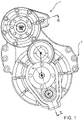
Figure 1 illustrates a schematic, side view of a traction assembly according to the invention; -
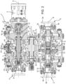
Figure 2 illustrates a front cross-section view along the line II-II of the assembly inFigure 1 ; -
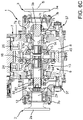
Figures 3A-3C illustrate different operating conditions of a portion of the assembly illustrated inFigure 2 ; -
Figures 4A-4B illustrate different operating conditions of a portion of the assembly illustrated inFigure 2 ; -
Figures 5A-5B illustrate different operating conditions of a portion of the assembly illustrated inFigure 2 ; and -
Figures 6A-6C illustrate different operating conditions of a portion of the assembly illustrated inFigure 2 . - The
reference number 1 indicates, in the attached figures, a traction assembly according to the invention configured to transmit torque tocorresponding couplings - In particular, the
traction assembly 1 is configured to provide torque to thecouplings input clutch 4 configured to be connected to a combustion engine (not illustrated) of the vehicle and at least oneelectric machine 5, described, below, for brevity, as an electric motor, configured to provide torque using electricity, for example provided by a vehicle battery set (not illustrated) or to absorb torque to generate electricity to provide to this battery set. - The
traction assembly 1 comprises atransmission 6 operationally placed between thecouplings input clutch 4 and the at least oneelectric motor 5 configured to enable the transmission of torque according to at least one speed ratio. - Advantageously, the
traction assembly 1 comprises acasing 7 configured to delimit aspace 8 that is isolated from the outside; thespace 8 is configured to house thetransmission 6 as described below. Preferably, thecasing 7 comprises acentral portion 7a and a pair ofside portions 7b placed near thecouplings - As illustrated in
Figure 2 , thetransmission 6 comprises aninput shaft 11 rotationally supported by thecentral portion 7a of thecasing 7 via a pair ofrolling supports 12 around an axis A and extending partially outside thecasing 7. Theinput clutch 4 basically comprises aconnection plate 9 that can be connected to the internal combustion engine and to theshaft 11 as described below. - The
transmission 6 comprises adifferential assembly 13 that is operationally placed between thecouplings shaft 11. - More precisely, the
couplings plate casing 7, in particular by theside portions 7b of the latter, and ahub casing 7 and rotationally supported on theside portion 7b of the latter via therolling supports 12. - In particular, the
hubs shaft 11. - The
hubs differential assembly 13 as described, in detail, below. - The
differential assembly 13 may be, as illustrated, of a known type, i.e., comprising achain carrier 14 carrying multiple planet gears 15, for example four planet gears equally angularly spaced apart by 90° and supported by across-shaped support 16 that is rigidly carried by thechain carrier 14 and around which arms can rotate the planet gears 15. In particular, the planet gears rotate on thesupport 14 around axes contained on a plane perpendicular to the axis B. - The planet gears 15 cooperate with a corresponding crown wheel comprising, respectively, a conic, left
toothed wheel 17a and a righttoothed wheel 17b rigidly carried by correspondingsupport shafts casing 7, around the axis B and, thus, coaxially between them; advantageously, thesesupport shafts central portion 7a using rolling supports 12. - In particular, the
differential assembly 13 is operationally connected to theshaft 11 via areducer assembly 21 comprising asupport shaft 22 carried rotationally freely by thecasing 7 around an axis C using rolling supports 12, in particular by thecentral portion 7a in a vertical position between theshaft 11 and thedifferential assembly 13. - Specifically, the
support shaft 22 defines atoothing 23 rigidly carried by thesupport shaft 22 and, preferably, advantageously made of a single piece with the same and supports a pair oftoothed wheels toothing 23. Thetoothed wheels support shaft 22. - The
shaft 11 carries a pair oftoothed wheels toothed wheels shaft 11. - The
transmission 6 comprises selector means 30 that are configured to make one of thetoothed wheels shaft 11 and additional selector means 30 configured to selectively connect the output shaft of theelectric motor 5 to theshaft 11 and additional selector means 30 to selectively connect theinput clutch 4 to theshaft 11. - Preferably, these selector means 30 comprise a
sleeve 31 carried integral to the rotation but free in its translation on the axis A by theshaft 11. In particular, thesleeve 31 defines atoothing 32 configured to cooperate with atoothing 33 made on theshaft 11. - The
toothed wheels toothings electric motor 5 and theinput clutch 4 carry corresponding toothings 36. Thesleeve 31 is sized so that, running along the axis A, it can mesh itstoothing 32 with thetoothing 33 of theshaft 11 and one of thetoothings toothed wheels input clutch 4 and/or of theelectric motor 5. - In particular, the selector means 30 comprise actuator means 37 configured to move the
sleeve 31 along theshaft 11. Advantageously, these actuator means 37 are pneumatic actuator means. - Preferably, according to the embodiment described, these actuator means 37 comprise a
rod 38 carried rigidly by ashaft 39 equipped, at its respective ends, with at least onefree piston 41 to move in arespective chamber 42 configured to selectively house a fluid under pressure, for example compressed air. - As best illustrated in
Figures 3A-3C ,4A-4B , and5A-5B , the actuator means 37 between thetoothed wheels pistons 41 and twochambers 42 while the actuator means 37 respectively placed between theinput clutch 4,electric motor 5, andshaft 11 comprise just onepiston 41 and just onechamber 42. - Advantageously, the actuator means 37 also comprise
elastic means 43 such as ahelical spring 44, operationally placed between theshaft 39 and thecasing 7. In particular: - the
sleeve 31 placed between thetoothed wheels sleeve 31 meshed with thetoothed wheel 26 when there is no compressed fluid in one of the chambers 42 (as illustrated inFigures 4A -4C); - the
sleeve 31 placed between theinput clutch 4 and theshaft 11 is pushed by the elastic means 43 so as to keep thesleeve 31 meshed with theinput clutch 4 when there is no compressed fluid in one of the chambers 42 (as illustrated inFigures 4A-4B ); and - the
sleeve 31 placed between theelectric motor 5 and theshaft 11 is pushed by the elastic means 43 so as to keep thesleeve 31 idle on the output shaft of theelectric motor 5 when there is no compressed fluid in one of the chambers 42 (as illustrated inFigures 5A-5B ). - The
toothing 23 of thesupport shaft 22 meshes with atoothing 45 carried integrally by thechain carrier 14 of thedifferential assembly 13. In the embodiment described, thechain carrier 14 is divided into two axial portions, symmetrical with each other, and thetoothing 45 is made on a circular crown fixed between the two axial portions of thechain carrier 14 via threaded connection means. - With reference, now, to
Figures 6A-6C , it should be noted how, preferably, thehub 2b of thecoupling 2 is separated from thesupport shaft 18a while it should be noted how thehub 3b of thecoupling 3 consists of a single piece with thesupport shaft 18b. - The
transmission 6 comprises selector means 60 to select an integral traction of the vehicle, i.e., to enable the provision of output torque from the differential to both thecouplings - According to the above, the selector means 60 are configured to connect the
hub 2b of thecoupling 2 to thesupport shaft 18a. In particular, the selector means 60 comprise asleeve 61 equipped with correspondingtoothings - The
sleeve 61 is supported, integral in rotation but free to run along the axis B, for example via a grooved coupling, on thesupport shaft 18a and is configured to assume a first position in which thetoothing 62 cooperates with anothertoothing 64 carried rigidly by thehub 2b and a second position in which thetoothing 63 cooperates with a toothing 65 that is rigidly carried by thesupport shaft 18a. - The
sleeve 61 is controlled via actuator means 37 controlling the selection of thesleeve 61 similarly to the selection of thetoothed wheels toothings - The
transmission 6 comprises locking means 70 of thedifferential assembly 13 to inhibit operation thereof. - According to the above, the locking means 70 are configured to connect the
chain carrier 14 to thecasing 7. - In particular, the locking means 70 comprise a
sleeve 71 supported, integral in rotation but free to run along the axis B, for example using a grooved coupling, on thesupport shaft 18b. Thesleeve 71 is equipped with a toothing 72 that is axial and is configured to assume a first position in which the toothing 72 cooperates with anothertoothing 73 carried rigidly by thecasing 7 and a second position in integral rotation with thesupport shaft 18b, in neutral. - The
sleeve 71 is controlled using actuator means 37 controlling the selection of thesleeve 61 similarly to the selection of thetoothed wheels sleeve 71 rotates idly with thesupport shaft 18b. - Referring to
Figure 1 , the relative arrangement between thecouplings input clutch 4, theelectric motor 5, and thesupport shaft 22 is clear, where it should be noted that theelectric motor 5 and theinput clutch 4 are carried on opposite sides to thecasing 7 but colinear between them along the axis A. In particular, theelectric motor 5 is connected to the outside of thecasing 7 so that its output shaft passes through it in thespace 8. - In particular, the axis B is placed vertically below the axis A of the
input clutch 4 of theelectric motor 5. In particular, the axis C of thesupport shaft 22 coincides with a vertical axis passing through the axis B and is vertically placed between the axes A and D. - Clearly, additional mechanical elements such as additional, sliding, rolling supports, gaskets, and fasteners although illustrated are not described for brevity's sake and since they relate to particular constructions that may vary depending on different assembly and manufacturing settings.
- The operation of the
traction assembly 1 according to the invention as described above is as follows. - In a first, purely thermal, operating condition, the torque released to the
couplings input clutch 2. In this configuration, represented by the combination of the states inFigure 4A ,Figure 5A , andFigures 3B, 3C , the actuator means 30 select one of thetoothed wheels shaft 11 while the output shaft of the electric motor is disconnected from theshaft 11 and theinput clutch 4 is connected to it. The torque provided thus to theshaft 11 flows via the coupling with the correspondingtoothed wheel support shaft 22 and, via the gear between thetoothings toothed wheels hubs - In a second operating condition, purely electrical, the torque released to the
couplings electric motor 5. In this configuration, represented by the combination of the states inFigure 4B ,Figure 5B , andFigures 3B, 3C , the actuator means 30 select one of thetoothed wheels shaft 11, while theinput clutch 4 is disconnected from theshaft 11 and theelectric motor 5 is connected to it. The torque provided thus to theshaft 11 flows via the coupling with the correspondingtoothed wheel support shaft 22 and, via the gear between thetoothings toothed wheels hubs - In a third, hybrid, operating condition, the torque released to the
couplings electric motor 5 and theinput clutch 4 or only by the latter and part is used by theelectric motor 5 as generator or all the drive torque from the input clutch is absorbed by theelectric motor 5. In this configuration, represented by the combination of the states inFigure 4A ,5B andFigure 3A/3B/3C , the actuator means 30 select one of thetoothed wheels shaft 11, or none of these, and connect both theelectric motor 5 and theinput clutch 2 to theshaft 11. The torque provided thus to theshaft 11 flows via the corresponding toothed couplings to thesupport shaft 22, and via the gear between thetoothings toothed wheels hubs toothed wheel electric motor 5. - In each of the three operating conditions described above, each equipped with two speeds, three operating variants as described below can also be selected.
- In a first operating variant (
Figure 6A ), the selector means 30 keep thehub 2b of thefront coupling 2 separated from thehub 18a of thetoothed wheel 17a. In this way, the vehicle operates according to a rear traction configuration and all the traction torque flows towards therear coupling 3. - In a second operating variant (
Figure 6C ), the selector means 30 make thehub 2b integral with thefront coupling 2 separated from thehub 18a of thetoothed wheel 17a. In this way, the vehicle operates according to an integral traction configuration and the differential 13 distributes the traction torque among thecouplings - In a third operating variant (
Figure 6B ), potentially combined with the two preceding ones, the selector means 30 make thechain carrier 14 integral with thecasing 7, locking the differential and making the rear coupling rotate (as illustrated or both combining with the operation inFigure 6C ) at the same speed as thechain carrier 14. - In view of the operations included above in
Figure 6A and6C , the vehicle comprises, advantageously, a front axle equipped with free-wheeling devices, advantageously integrated in wheels, configured to enable the operation in neutral of the hub since thefront coupling 2 is not integral with thehub 18a. - The advantages of a traction assembly according to the invention are clear from the foregoing.
- The traction system makes it possible, as shown by the high number of operating combinations illustrated, to provide a great variety of traction transmission ratios that are completely thermal, completely electric, hybrid, those with integral or rear traction, or with locked differential.
- The traction system is also particularly compact and uses few mechanical elements; thus, the manufacturing costs are reduced.
- Again, although all the rotating mechanical elements are inside the casing of the transmission, which is lubricated, the service life of the traction system is increased and the maintenance costs decrease.
- Lastly, it is clear that modifications and variations may be made to the traction assembly and vehicle manufactured according to the present invention, without however departing from the scope of protection defined by the claims.
- For example, it is clear that the toothed wheels described, the differential, and other types of mechanical connection may be replaced by equivalent devices.
- Similarly, the number of electric motors or the shape of the casing may vary or, again, the reduction stage may involve more speed shifts.
- Again, although as described just one front coupling can disconnect from the differential 13, it is possible to provide for the similar disconnection to the rear coupling providing a purely frontal traction system.
Claims (15)
- - A traction assembly (1) for a vehicle, said traction assembly (1) comprising a first and a second coupling (2, 3) configured to be connected respectively to a front axle and a rear axle of said vehicle, an input clutch (4) configured to be connected to an output shaft of an internal combustion engine of said vehicle and at least one electric machine (5), said traction assembly (1) comprising a casing (7) defining a housing (8) and a transmission (6) housed in said housing (8) and configured to allow torque transmission between said input clutch (4), the at least one electric machine (5) and the couplings (2, 3), said transmission (6) being controlled so as to allow torque transmission according to one of:- a mode where only said input coupling (4) provides torque to said couplings (2, 3);- a mode where only said at least one electric machine (5) supplies torque to said couplings (2, 3); and- a mode where both between said inlet (4) and said at least one electric machine (5) supplies torque to said couplings (2,3),wherein said transmission (6) comprises a differential (13) comprising a first output hub (18a) connectable to said first coupling (2) and a second output hub (18b) connectable to said second coupling (3), said hubs (18a, 18b) and said couplings (2, 3) being coaxial to each other along an axis (B),said transmission (6) comprising a shaft (11) supported in a rotationally free way around an axis (A) on said casing (7), said input clutch (4) and said at least one electric machine (5) being connectable to called tree (11),said shaft (11) being operatively connected to said differential (13) through at least one torque transmission ratio.
- - The assembly according to Claim 1, wherein said shaft (11) carries toothed wheels (26, 27), said assembly comprising selector means (30) configured to operatively connect one of said toothed wheels (26, 27) to said differential (13).
- - The assembly according to claim 1 or 2, in which said input coupling (4) and said at least one electric machine (5) can be selectively connected to the shaft (11) through selector means (30).
- - The assembly according to one of claims 1 to 3, wherein said transmission (6) comprises a reduction stage (21) operatively interposed between the shaft (11) and said differential (13).
- - The assembly according to claim 4, where said reduction stage (21) comprises a support shaft (22) carried in a rotationally free manner by said casing (7) around an axis (C), said support shaft comprising a pair of toothed wheels (24, 25) configured to cooperate with said toothed wheels (26, 27) of said shaft (11), said support shaft (22) defining a toothing (23) configured to cooperate with said differential (13).
- The assembly according to Claim 5, wherein said differential (13) is connected to said toothing (23) by means of a toothing (45) carried rigidly by the chain carrier (14) of said differential (13).
- - The assembly according to one of claims 2 to 6, in which said selector means (30) comprise a sleeve (31) movable under the action of said actuator means (37) along the shaft (11) in a rotationally coupled manner , said sleeve (31) defining a toothing (32) configured to cooperate with a toothing (33) made on said shaft (11) and with a further toothing (34, 35, 36) made on the element to be connected to said shaft ( 11), said sleeve (31) being sized and controlled by said actuator means (37) so as to assume a position in which it does not mesh with any of said further toothings (34, 35, 36) and a position in which it meshes with a of them.
- - The assembly according to one of the previous claims, wherein said transmission (6) comprises selector means (60) configured to make one of said first and second hubs (18a, 18b) integral with the respective first and second coupling (2, 3).
- The assembly according to claim 8, wherein said selector means (60) comprise a sleeve (61) movable under the action of said actuator means (37) along the respective hub (18a, 18b) in a rotationally coupled manner thereto, said sleeve (61) defining a first and a second toothing (62, 63) configured to selectively cooperate with a toothing (64) made on said coupling (2, 3) and a second toothing (65) made on said hub (18a, 18b).
- The assembly according to one of the previous claims, wherein said transmission (6) comprises locking means (70) of said differential (13) configured to lock the operation of said differential (13).
- The assembly according to claim 10, wherein said locking means (70) comprise a sleeve (71) movable under the action of said actuator means (37) along one of said hubs (18a, 18b) in a rotationally coupled manner thereto, said sleeve (71) defining a toothing (72) configured to selectively cooperate with a toothing (73) made on said casing (7).
- The assembly according to one of claims 2 to 11, wherein said actuator means (37) comprise at least one of a pneumatic, hydraulic, mechanical actuator.
- - The assembly according to one of the preceding claims, in which said at least one electric machine (5) is carried on the opposite side of said casing (7) with respect to said input coupling (4).
- - A vehicle comprising an internal combustion engine, a front axle and a rear axle and a traction assembly (1) according to one of the preceding claims.
- The vehicle according to claim 14, wherein at least one of said front and rear axle comprises freewheel means, said freewheel means being configured to allow the transmission of torque to the wheel hubs of said axle or to allow them to be supported in a neutral manner.
Applications Claiming Priority (1)
| Application Number | Priority Date | Filing Date | Title |
|---|---|---|---|
| IT102021000023018A IT202100023018A1 (en) | 2021-09-06 | 2021-09-06 | DRIVE ASSEMBLY FOR ONE VEHICLE |
Publications (1)
| Publication Number | Publication Date |
|---|---|
| EP4144554A1 true EP4144554A1 (en) | 2023-03-08 |
Family
ID=78649892
Family Applications (1)
| Application Number | Title | Priority Date | Filing Date |
|---|---|---|---|
| EP22193192.6A Pending EP4144554A1 (en) | 2021-09-06 | 2022-08-31 | Traction assembly for a vehicle |
Country Status (2)
| Country | Link |
|---|---|
| EP (1) | EP4144554A1 (en) |
| IT (1) | IT202100023018A1 (en) |
Citations (7)
| Publication number | Priority date | Publication date | Assignee | Title |
|---|---|---|---|---|
| US20080090692A1 (en) * | 2006-10-17 | 2008-04-17 | Gates Luther H | Transfer case center differential |
| US20090013809A1 (en) * | 2005-05-17 | 2009-01-15 | Magna Powertrain Ag & Co Kg | Manual Helical Planetary Transmission and Power Divider for Motor Vehicles Comprising Said Transmission |
| KR20120100499A (en) * | 2011-03-04 | 2012-09-12 | 현대다이모스(주) | Transfer case of 4wd vehicle |
| FR2975047A1 (en) * | 2011-05-12 | 2012-11-16 | IFP Energies Nouvelles | MOTOR POWERTRAIN FOR MOTOR VEHICLE WITH HYBRID DRIVE |
| EP3246187A1 (en) * | 2016-05-19 | 2017-11-22 | MAN Truck & Bus AG | Hybrid drive for a motor vehicle, in particular for a commercial vehicle |
| IT201900015422A1 (en) * | 2019-09-03 | 2021-03-03 | Iveco Spa | MODULAR ELECTRIC TRACTION SYSTEM |
| DE102019215124A1 (en) * | 2019-10-01 | 2021-04-01 | Zf Friedrichshafen Ag | Fire engine drive train and fire engine |
-
2021
- 2021-09-06 IT IT102021000023018A patent/IT202100023018A1/en unknown
-
2022
- 2022-08-31 EP EP22193192.6A patent/EP4144554A1/en active Pending
Patent Citations (7)
| Publication number | Priority date | Publication date | Assignee | Title |
|---|---|---|---|---|
| US20090013809A1 (en) * | 2005-05-17 | 2009-01-15 | Magna Powertrain Ag & Co Kg | Manual Helical Planetary Transmission and Power Divider for Motor Vehicles Comprising Said Transmission |
| US20080090692A1 (en) * | 2006-10-17 | 2008-04-17 | Gates Luther H | Transfer case center differential |
| KR20120100499A (en) * | 2011-03-04 | 2012-09-12 | 현대다이모스(주) | Transfer case of 4wd vehicle |
| FR2975047A1 (en) * | 2011-05-12 | 2012-11-16 | IFP Energies Nouvelles | MOTOR POWERTRAIN FOR MOTOR VEHICLE WITH HYBRID DRIVE |
| EP3246187A1 (en) * | 2016-05-19 | 2017-11-22 | MAN Truck & Bus AG | Hybrid drive for a motor vehicle, in particular for a commercial vehicle |
| IT201900015422A1 (en) * | 2019-09-03 | 2021-03-03 | Iveco Spa | MODULAR ELECTRIC TRACTION SYSTEM |
| DE102019215124A1 (en) * | 2019-10-01 | 2021-04-01 | Zf Friedrichshafen Ag | Fire engine drive train and fire engine |
Also Published As
| Publication number | Publication date |
|---|---|
| IT202100023018A1 (en) | 2023-03-06 |
Similar Documents
| Publication | Publication Date | Title |
|---|---|---|
| US8864619B2 (en) | Planetary power take off device | |
| CN216139798U (en) | Electric drive axle | |
| EP4039497B1 (en) | Drive axle assembly for vehicle | |
| JP6474478B1 (en) | Power transmission device and vehicle including the same | |
| EP4039496B1 (en) | Drive axle assembly for vehicle | |
| EP4399111B1 (en) | Traction assembly for a vehicle | |
| JP2019529838A (en) | Multi-speed transmission | |
| JP2003127688A (en) | Power transmission device | |
| JP2019078366A (en) | Power transmission device, and vehicle including the same | |
| US11472226B2 (en) | Lubricant supported electric motor with wheel support | |
| EP4422898B1 (en) | Traction assembly for a vehicle | |
| EP4144554A1 (en) | Traction assembly for a vehicle | |
| EP4144552B1 (en) | Traction assembly for a vehicle | |
| US11156281B2 (en) | Axle assembly with lubrication pump | |
| JP5039647B2 (en) | Power transmission device | |
| CN116424033B (en) | Automobile duplex driving axle | |
| US12606019B2 (en) | Electric traction axle/beam | |
| EP4257401A1 (en) | Improved torque distributor system among axles of a heavy vehicle | |
| EP4257389A1 (en) | Improved torque distribution system among axles of a heavy vehicle | |
| EP4257388A1 (en) | Improved torque distributor system among axles of a heavy vehicle | |
| KR102761000B1 (en) | Coaxial 2-speed transmission for electric vehicle | |
| JP4516655B2 (en) | Starting clutch | |
| EP4541629A1 (en) | Improved electric traction axle | |
| EP4541630A1 (en) | Improved electric traction axle | |
| WO2025083603A1 (en) | Improved electric traction axle/beam |
Legal Events
| Date | Code | Title | Description |
|---|---|---|---|
| PUAI | Public reference made under article 153(3) epc to a published international application that has entered the european phase |
Free format text: ORIGINAL CODE: 0009012 |
|
| STAA | Information on the status of an ep patent application or granted ep patent |
Free format text: STATUS: THE APPLICATION HAS BEEN PUBLISHED |
|
| AK | Designated contracting states |
Kind code of ref document: A1 Designated state(s): AL AT BE BG CH CY CZ DE DK EE ES FI FR GB GR HR HU IE IS IT LI LT LU LV MC MK MT NL NO PL PT RO RS SE SI SK SM TR |
|
| STAA | Information on the status of an ep patent application or granted ep patent |
Free format text: STATUS: REQUEST FOR EXAMINATION WAS MADE |
|
| 17P | Request for examination filed |
Effective date: 20230904 |
|
| RBV | Designated contracting states (corrected) |
Designated state(s): AL AT BE BG CH CY CZ DE DK EE ES FI FR GB GR HR HU IE IS IT LI LT LU LV MC MK MT NL NO PL PT RO RS SE SI SK SM TR |
|
| STAA | Information on the status of an ep patent application or granted ep patent |
Free format text: STATUS: EXAMINATION IS IN PROGRESS |
|
| 17Q | First examination report despatched |
Effective date: 20250804 |