EP4144533A1 - Head unit and inkjet recording device - Google Patents
Head unit and inkjet recording device Download PDFInfo
- Publication number
- EP4144533A1 EP4144533A1 EP22756079.4A EP22756079A EP4144533A1 EP 4144533 A1 EP4144533 A1 EP 4144533A1 EP 22756079 A EP22756079 A EP 22756079A EP 4144533 A1 EP4144533 A1 EP 4144533A1
- Authority
- EP
- European Patent Office
- Prior art keywords
- head
- recording
- recording head
- adjusting screw
- frame
- Prior art date
- Legal status (The legal status is an assumption and is not a legal conclusion. Google has not performed a legal analysis and makes no representation as to the accuracy of the status listed.)
- Granted
Links
Images


Classifications
-
- B—PERFORMING OPERATIONS; TRANSPORTING
- B41—PRINTING; LINING MACHINES; TYPEWRITERS; STAMPS
- B41J—TYPEWRITERS; SELECTIVE PRINTING MECHANISMS, i.e. MECHANISMS PRINTING OTHERWISE THAN FROM A FORME; CORRECTION OF TYPOGRAPHICAL ERRORS
- B41J2/00—Typewriters or selective printing mechanisms characterised by the printing or marking process for which they are designed
- B41J2/005—Typewriters or selective printing mechanisms characterised by the printing or marking process for which they are designed characterised by bringing liquid or particles selectively into contact with a printing material
- B41J2/01—Ink jet
- B41J2/21—Ink jet for multi-colour printing
- B41J2/2132—Print quality control characterised by dot disposition, e.g. for reducing white stripes or banding
- B41J2/2146—Print quality control characterised by dot disposition, e.g. for reducing white stripes or banding for line print heads
-
- B—PERFORMING OPERATIONS; TRANSPORTING
- B41—PRINTING; LINING MACHINES; TYPEWRITERS; STAMPS
- B41J—TYPEWRITERS; SELECTIVE PRINTING MECHANISMS, i.e. MECHANISMS PRINTING OTHERWISE THAN FROM A FORME; CORRECTION OF TYPOGRAPHICAL ERRORS
- B41J2/00—Typewriters or selective printing mechanisms characterised by the printing or marking process for which they are designed
- B41J2/005—Typewriters or selective printing mechanisms characterised by the printing or marking process for which they are designed characterised by bringing liquid or particles selectively into contact with a printing material
- B41J2/01—Ink jet
- B41J2/135—Nozzles
- B41J2/14—Structure thereof only for on-demand ink jet heads
- B41J2/1433—Structure of nozzle plates
-
- B—PERFORMING OPERATIONS; TRANSPORTING
- B41—PRINTING; LINING MACHINES; TYPEWRITERS; STAMPS
- B41J—TYPEWRITERS; SELECTIVE PRINTING MECHANISMS, i.e. MECHANISMS PRINTING OTHERWISE THAN FROM A FORME; CORRECTION OF TYPOGRAPHICAL ERRORS
- B41J25/00—Actions or mechanisms not otherwise provided for
- B41J25/001—Mechanisms for bodily moving print heads or carriages parallel to the paper surface
- B41J25/003—Mechanisms for bodily moving print heads or carriages parallel to the paper surface for changing the angle between a print element array axis and the printing line, e.g. for dot density changes
-
- B—PERFORMING OPERATIONS; TRANSPORTING
- B41—PRINTING; LINING MACHINES; TYPEWRITERS; STAMPS
- B41J—TYPEWRITERS; SELECTIVE PRINTING MECHANISMS, i.e. MECHANISMS PRINTING OTHERWISE THAN FROM A FORME; CORRECTION OF TYPOGRAPHICAL ERRORS
- B41J25/00—Actions or mechanisms not otherwise provided for
- B41J25/34—Bodily-changeable print heads or carriages
Definitions
- the present invention relates to a head unit and to an ink-jet recording apparatus.
- a head unit incorporated in an ink-jet recording apparatus includes a recording head having a plurality of nozzles for ejecting ink on a recording medium such as a sheet, and records an image on the recording medium.
- a recording head having a plurality of nozzles for ejecting ink on a recording medium such as a sheet, and records an image on the recording medium.
- Patent Document 1 identified below.
- Patent Document 1 discloses a known ink-jet recording apparatus that includes a head assembly (head unit) having three recording heads.
- the recording heads are coupled to a base member of the head assembly with a coupling member.
- Patent Document 1 Japanese Patent Application published as No. 2020-121514 .
- an object of the present invention is to provide a head unit and an ink-jet recording apparatus that allows easy replacement of a recording head as well as cost reduction.
- a head unit includes a recording head, a frame, and an angle adjusting portion.
- the recording head has a plurality of nozzles for ejecting ink on a recording medium.
- the frame has a side wall that extends in a width direction perpendicular to a conveying direction of the recording medium to be adj acent to the recording head.
- the recording head is connected rotatably about a head rotary shaft arranged in an end part of the recording head in the width direction.
- the angle adjusting portion is arranged at an other end part side of the recording head, opposite from the head rotary shaft in the width direction, and rotates the recording head about the head rotary shaft.
- the angle adjusting portion includes a frame adjusting screw and a head adjusting screw.
- the frame adjusting screw is provided on the side wall, on its face opposite the recording head.
- the frame adjusting screw can reciprocate in directions toward and away from the recording head.
- the head adjusting screw is provided on the recording head, on its face opposite the side wall.
- the head adjusting screw can reciprocate in directions toward and away from the side wall.
- the frame adjusting screw and the head adjusting screw make contact with each other at their tip end parts in the direction in which they face each other.
- Fig. 1 is a schematic sectional view of an ink-jet recording apparatus 1 according to an embodiment.
- Fig. 2 is a plan view of a recording portion 5 in the ink-jet recording apparatus 1 in Fig. 1 .
- the ink-jet recording apparatus 1 is, for example, a printer of an ink-jet recording type.
- the ink-jet recording apparatus 1 includes, as shown in Figs. 1 and 2 , an apparatus main body 2, a sheet feeding portion 3, a sheet conveying portion 4, a recording portion 5, a drying portion 6, and a control portion 7.
- the sheet feeding portion 3 stores a plurality of sheets (of a recording medium) S and, during recording, feeds them out one after another separately.
- the sheet conveying portion 4 conveys a sheet S fed out from the sheet feeding portion 3 to the recording portion 5 and then to the drying portion 6, and then discharges the sheet S after recording and drying to a sheet discharge portion 21.
- the sheet conveying portion 4 switches, with a branch portion 43, the conveying direction of the sheet S after recording on its first side and drying to a reversing conveying portion 44, and conveys the sheet S having its conveying direction switched and its obverse and reverse sides reversed to the recording portion 5 and then to the drying portion 6 once again.
- the sheet conveying portion 4 includes first and second belt conveying portions 41 and 42.
- the first belt conveying portion 41 has a first conveying belt 411 formed so as to be endless.
- the second belt conveying portion 42 has a second conveying belt 421 formed so as to be endless.
- the first and second first belt conveying portions 41 and 42 convey a sheet S by holding it by suction on their upper outer faces (top faces).
- the first belt conveying portion 41 is arranged under the recording portion 5 and conveys the sheet S.
- the second belt conveying portion 42 is arranged downstream of the first belt conveying portion 41 in the sheet conveying direction in the drying portion 6 and conveys the sheet S.
- the recording portion 5 faces the sheet S that is conveyed while being held by suction on the top face of the first conveying belt 411 and is arranged above the first conveying belt 411 across a predetermined gap from it.
- the recording portion 5 includes head units 51B, 51C, 51M, and 51Y corresponding to four colors, namely black, cyan, magenta, and yellow.
- the head units 51B, 51C, 51M, and 51Y are arranged side by side along the sheet conveying direction Dc such that their longitudinal direction is parallel to the sheet width direction Dw perpendicular to the sheet conveying direction Dc.
- the four head units 51B, 51C, 51M, and 51Y have basically similar structures. Thus, in the following description, the suffixes "B”, “C”, “M”, and “Y” distinguishing different colors are often omitted, unless distinction is needed.
- the head units 51 for the different colors each include line recording heads 52 of an ink-jet type.
- a plurality of recording heads 52 (for example, three of them (52a, 52b, and 52c)) are arranged in a staggered formation along the sheet width direction Dw.
- the recording head 52 has a plurality of ink ejecting nozzles 521 in a bottom part of it.
- the plurality of ink ejecting nozzles 521 are arrayed along the sheet width direction Dw so that ink can be ejected over the entire recording region of the sheet S. That is, the recording head 52 has a plurality of ink ejecting nozzles 521 for ejecting ink on the sheet S.
- the recording portion 5 ejects ink sequentially from the recording heads 52 in the head units 51B, 51C, 51M, and 51Y of four colors toward the sheet S conveyed by the first conveying belt 411 so as to record on it a full-color image or a monochrome image.
- the drying portion 6 is arranged downstream of the recording portion 5 in the sheet conveying direction and includes the second belt conveying portion 42. While the sheet S with an ink image recorded on it in the recording portion 5 is being conveyed while being held by suction on the second conveying belt 421 in the drying portion 6, the ink is dried.
- the control portion 7 includes a CPU, a storage portion, and other electronic circuits and components (none of which are illustrated).
- the CPU based on control programs and data stored in the storage portion, controls the operation of different components provided in the ink-jet recording apparatus 1 to perform processing related to the functions of the ink-jet recording apparatus 1.
- the sheet feeding portion 3, the sheet conveying portion 4, the recording portion 5, and the drying portion 6 individually receive commands from the control portion 7 and coordinate to perform printing on the sheet S.
- the storage portion is composed of, for example, a combination of an unillustrated non-volatile storage device, such as a program ROM (read-only memory) and a data ROM, and an unillustrated volatile storage device, such as a RAM (randomaccess memory).
- Fig. 3 is a horizontal sectional view of the head unit 51 in the recording portion 5 in Fig. 2 .
- the head unit 51 includes, in addition to the recording head 52, a frame 53, a head rotary shaft 54, and an angle adjusting portion 8.
- the frame 53 holds three recording heads 52a, 52b, and 52c.
- the three recording heads 52a, 52b, and 52c are arranged in a staggered formation along the sheet width direction Dw.
- the frame 53 has a side wall 531.
- the side wall 531 extends in the up-down direction and in the sheet width direction Dw to make contact with the recording heads 52a, 52b, and 52c.
- the side wall 531 is arranged between two recording heads 52a and 52c and one recording head 52b in the sheet conveying direction Dc.
- the side wall 531 faces the side faces of the recording heads 52 on the downstream or upstream side in the sheet conveying direction Dc.
- the head rotary shaft 54 is one end part 52r of each recording head 52 in the longitudinal direction (sheet width direction Dw) and is arranged, for example, in an end part of the recording head 52 at the rear side of the recording portion 5.
- the rotation axis of the head rotary shaft 54 extends in the up-down direction, which is the direction normal to the top face of the first conveying belt 411.
- the three recording heads 52 are each connected to the frame 53 so as to be rotatable about the head rotary shaft 54.
- the recording head 52 is rotatable in a rotation direction Ra in which an other end part 52f side of it in the longitudinal direction (sheet width direction Dw) moves upstream in the sheet conveying direction Dc about the head rotary shaft 54, or in a rotation direction Rb in which the other end part 52f moves downstream in the sheet conveying direction Dc about the head rotary shaft 54.
- the angle adjusting portion 8 is arranged at the other end part 52f side of the recording head 52, opposite from the head rotary shaft 54, for example, in an end part of the recording head 52 at the front side of the recording portion 5.
- the angle adjusting portion 8 rotates the recording head 52 about the head rotary shaft 54 in the rotation direction Ra or Rb. In this way, the angle adjusting portion 8 can adjust the angle of the recording head 52 with respect to the frame 53 of the head unit 51; thus, it is possible to position the recording head 52 properly with respect to the head unit 51.
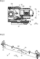
- Fig. 4 is a part horizontal sectional view of and around the angle adjusting portion 8 in the head unit 51 in Fig. 3 .
- Fig. 5 is a perspective view of the side wall 531 of the head unit 51 in Fig. 3 .
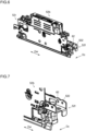
- Fig. 6 is a perspective view of the recording head 52 in the head unit 51 in Fig. 3 .
- Fig. 7 is a part perspective view of and around the angle adjusting portion 8 in the recording head 52 in Fig. 6 .
- the angle adjusting portion 8 includes a frame adjusting screw 81 and a head adjusting screw 82.
- the frame adjusting screw 81 is provided on the side wall 531, on its face opposite the recording head 52.
- the frame adjusting screw 81 is fitted perpendicularly to the side wall 531 so as to penetrate the side wall 531, and extends in a direction intersecting with the rotation axis of the head rotary shaft 54 (i.e., in the sheet conveying direction Dc).
- the frame adjusting screw 81 is, for example, a setscrew having a hexagonal hole or a slot formed in an end part of it.
- the frame adjusting screw 81 can reciprocate in directions toward and away from the recording head 52.
- the head adjusting screw 82 is provided on the recording head 52, on its face opposite the side wall 531.
- the head adjusting screw 82 is fitted perpendicularly to a side plate 522 of the recording head 52 so as to penetrate the side plate 522, and extends in a direction intersecting with the rotation axis of the head rotary shaft 54 (i.e., in the sheet conveying direction Dc).
- the head adjusting screw 82 is, for example, a setscrew having a hexagonal hole and a slot formed in an end part of it.
- the head adjusting screw 82 can reciprocate in directions toward and away from the side wall 531.
- the frame adjusting screw 81 and the head adjusting screw 82 are arranged at positions at which they face each other in a direction intersecting with the rotation axis of the head rotary shaft 54 (i.e., in the sheet conveying direction Dc). That is, the frame adjusting screw 81 and the head adjusting screw 82 are arranged at positions at which they face each other in the longitudinal direction (sheet width direction Dw) of the head unit 51 and in the up-down direction, and their extending directions (moving directions) are the same.
- the frame adjusting screw 81 and the head adjusting screw 82 make contact with each other at tip end parts of them in the direction in which they face each other.
- the recording head 52 is fitted to the frame 53, and the frame adjusting screw 81 is adjusted in the frame 53.
- This allows easy replacement of the recording head 52 alone. There is also no need to replace any other components unnecessarily, and this permits cost reduction.
- a new recording head 52 is fitted to the frame 53 that has the frame adjusting screw 81 already adjusted; thus, a user can easily adjust alignment.
- the head unit 51 includes a plurality of (three in this embodiment) recording heads 52 that are arranged side by side in the sheet width direction Dw. With this construction, when, for example, one recording head 52 needs to be replaced, the other two recording heads 52 can continue to be used without necessity of replacement. Thus, it is possible to reduce the cost of the head unit 51.
- the three recording heads 52a, 52b, and 52c are, as described above, arranged in a staggered formation along the sheet width direction Dw (see Fig. 3 ).
- Two recording heads 52a and 52c are arranged upstream of the side wall 531 in the sheet conveying direction Dc, and one recording head 52b is arranged downstream of the side wall 531 in the sheet conveying direction Dc. That is, a plurality of recording heads 52 are arranged both upstream and downstream of the side wall 531 in the sheet conveying direction Dc.
- the ink-jet recording apparatus 1 includes the head unit 51 constructed as described above which records an image on the sheet S. With this construction, it is possible to provide an ink-jet recording apparatus 1 that has a low-cost construction and that allows easy replacement of a recording head 52.
- the present invention is applicable to head units and ink-jet recording apparatuses.
Landscapes
- Engineering & Computer Science (AREA)
- Quality & Reliability (AREA)
- Ink Jet (AREA)
Abstract
Description
- The present invention relates to a head unit and to an ink-jet recording apparatus.
- A head unit incorporated in an ink-jet recording apparatus includes a recording head having a plurality of nozzles for ejecting ink on a recording medium such as a sheet, and records an image on the recording medium. One example of such head units is disclosed in
Patent Document 1 identified below. -
Patent Document 1 discloses a known ink-jet recording apparatus that includes a head assembly (head unit) having three recording heads. The recording heads are coupled to a base member of the head assembly with a coupling member. - Patent Document 1:
Japanese Patent Application published as No. 2020-121514 - With the known technology, if, when a user is using the ink-jet recording apparatus, a fault or the like occurs that requires replacement of a recording head, it is difficult to replace the recording head alone and, inconveniently, the whole head assembly needs to be replaced. Thus, it is necessary to replace also another component unnecessarily, and there is thus concern for increased cost. Also, even if the recording head alone can be replaced, it is not possible for a user to align the new recording head with respect to the existing base member.
- In view of the situation described above, an object of the present invention is to provide a head unit and an ink-jet recording apparatus that allows easy replacement of a recording head as well as cost reduction.
- To achieve the above object, a head unit according to the present invention includes a recording head, a frame, and an angle adjusting portion. The recording head has a plurality of nozzles for ejecting ink on a recording medium. The frame has a side wall that extends in a width direction perpendicular to a conveying direction of the recording medium to be adj acent to the recording head. To the frame, the recording head is connected rotatably about a head rotary shaft arranged in an end part of the recording head in the width direction. The angle adjusting portion is arranged at an other end part side of the recording head, opposite from the head rotary shaft in the width direction, and rotates the recording head about the head rotary shaft. The angle adjusting portion includes a frame adjusting screw and a head adjusting screw. The frame adjusting screw is provided on the side wall, on its face opposite the recording head. The frame adjusting screw can reciprocate in directions toward and away from the recording head. The head adjusting screw is provided on the recording head, on its face opposite the side wall. The head adjusting screw can reciprocate in directions toward and away from the side wall. The frame adjusting screw and the head adjusting screw make contact with each other at their tip end parts in the direction in which they face each other.
- With this construction, during the assembly of the head unit, after the head adjusting screw is adjusted in the recording head, the recording head is fitted to the frame, and the frame adjusting screw is adjusted in the frame. This allows easy replacement of the recording head alone. There is also no need to replace any other components unnecessarily, and this permits cost reduction. Furthermore, when the recording head is replaced, a new recording head is fitted to the frame that has the frame adjusting screw already adjusted; thus, a user can easily adjust alignment.
-
-
Fig. 1 is a schematic sectional front view of an ink-jet recording apparatus according to one embodiment of the present invention; -
Fig. 2 is a plan view of a recording portion in the ink-jet recording apparatus 1 inFig. 1 ; -
Fig. 3 is a horizontal sectional view of a head unit in the recording portion inFig. 2 ; -
Fig. 4 is a part horizontal sectional view of and around an angle adjusting portion in the head unit inFig. 3 ; -
Fig. 5 is a perspective view of a side wall of the head unit inFig. 3 ; -
Fig. 6 is a perspective view of a recording head in the head unit inFig. 3 ; and -
Fig. 7 is a part perspective view of and around the angle adjusting portion in the recording head inFig. 6 . - An embodiment of the present invention will be described below with reference to the accompanying drawings. The present invention is, however, not limited to what is specifically described below.
-
Fig. 1 is a schematic sectional view of an ink-jet recording apparatus 1 according to an embodiment.Fig. 2 is a plan view of arecording portion 5 in the ink-jet recording apparatus 1 inFig. 1 . The ink-jet recording apparatus 1 is, for example, a printer of an ink-jet recording type. The ink-jet recording apparatus 1 includes, as shown inFigs. 1 and 2 , an apparatusmain body 2, asheet feeding portion 3, a sheet conveying portion 4, arecording portion 5, a drying portion 6, and acontrol portion 7. - The
sheet feeding portion 3 stores a plurality of sheets (of a recording medium) S and, during recording, feeds them out one after another separately. The sheet conveying portion 4 conveys a sheet S fed out from thesheet feeding portion 3 to therecording portion 5 and then to the drying portion 6, and then discharges the sheet S after recording and drying to asheet discharge portion 21. When duplex recording is performed, the sheet conveying portion 4 switches, with abranch portion 43, the conveying direction of the sheet S after recording on its first side and drying to a reversing conveyingportion 44, and conveys the sheet S having its conveying direction switched and its obverse and reverse sides reversed to therecording portion 5 and then to the drying portion 6 once again. - The sheet conveying portion 4 includes first and second
belt conveying portions belt conveying portion 41 has a first conveyingbelt 411 formed so as to be endless. The secondbelt conveying portion 42 has a second conveyingbelt 421 formed so as to be endless. The first and second firstbelt conveying portions belt conveying portion 41 is arranged under therecording portion 5 and conveys the sheet S. The secondbelt conveying portion 42 is arranged downstream of the firstbelt conveying portion 41 in the sheet conveying direction in the drying portion 6 and conveys the sheet S. - The
recording portion 5 faces the sheet S that is conveyed while being held by suction on the top face of the first conveyingbelt 411 and is arranged above the first conveyingbelt 411 across a predetermined gap from it. As shown inFig. 2 , therecording portion 5 includeshead units head units head units - The
head units 51 for the different colors each include line recording heads 52 of an ink-jet type. In each of thehead units 51 for the different colors, a plurality of recording heads 52 (for example, three of them (52a, 52b, and 52c)) are arranged in a staggered formation along the sheet width direction Dw. - The
recording head 52 has a plurality ofink ejecting nozzles 521 in a bottom part of it. The plurality ofink ejecting nozzles 521 are arrayed along the sheet width direction Dw so that ink can be ejected over the entire recording region of the sheet S. That is, therecording head 52 has a plurality ofink ejecting nozzles 521 for ejecting ink on the sheet S. Therecording portion 5 ejects ink sequentially from therecording heads 52 in thehead units first conveying belt 411 so as to record on it a full-color image or a monochrome image. - The drying portion 6 is arranged downstream of the
recording portion 5 in the sheet conveying direction and includes the secondbelt conveying portion 42. While the sheet S with an ink image recorded on it in therecording portion 5 is being conveyed while being held by suction on the second conveyingbelt 421 in the drying portion 6, the ink is dried. - The
control portion 7 includes a CPU, a storage portion, and other electronic circuits and components (none of which are illustrated). The CPU, based on control programs and data stored in the storage portion, controls the operation of different components provided in the ink-jet recording apparatus 1 to perform processing related to the functions of the ink-jet recording apparatus 1. Thesheet feeding portion 3, the sheet conveying portion 4, therecording portion 5, and the drying portion 6 individually receive commands from thecontrol portion 7 and coordinate to perform printing on the sheet S. The storage portion is composed of, for example, a combination of an unillustrated non-volatile storage device, such as a program ROM (read-only memory) and a data ROM, and an unillustrated volatile storage device, such as a RAM (randomaccess memory). - Next, the construction of the
head unit 51 in the ink-jet recording apparatus 1 will be described with reference toFig. 3 as well asFig. 2 .Fig. 3 is a horizontal sectional view of thehead unit 51 in therecording portion 5 inFig. 2 . - The
head unit 51 includes, in addition to therecording head 52, aframe 53, ahead rotary shaft 54, and anangle adjusting portion 8. - The
frame 53 holds threerecording heads recording heads frame 53 has aside wall 531. Theside wall 531 extends in the up-down direction and in the sheet width direction Dw to make contact with the recording heads 52a, 52b, and 52c. Theside wall 531 is arranged between tworecording heads recording head 52b in the sheet conveying direction Dc. Theside wall 531 faces the side faces of the recording heads 52 on the downstream or upstream side in the sheet conveying direction Dc. - The
head rotary shaft 54 is oneend part 52r of eachrecording head 52 in the longitudinal direction (sheet width direction Dw) and is arranged, for example, in an end part of therecording head 52 at the rear side of therecording portion 5. The rotation axis of thehead rotary shaft 54 extends in the up-down direction, which is the direction normal to the top face of the first conveyingbelt 411. - The three recording heads 52 are each connected to the
frame 53 so as to be rotatable about thehead rotary shaft 54. Therecording head 52 is rotatable in a rotation direction Ra in which another end part 52f side of it in the longitudinal direction (sheet width direction Dw) moves upstream in the sheet conveying direction Dc about thehead rotary shaft 54, or in a rotation direction Rb in which theother end part 52f moves downstream in the sheet conveying direction Dc about thehead rotary shaft 54. - The
angle adjusting portion 8 is arranged at theother end part 52f side of therecording head 52, opposite from thehead rotary shaft 54, for example, in an end part of therecording head 52 at the front side of therecording portion 5. Theangle adjusting portion 8 rotates therecording head 52 about thehead rotary shaft 54 in the rotation direction Ra or Rb. In this way, theangle adjusting portion 8 can adjust the angle of therecording head 52 with respect to theframe 53 of thehead unit 51; thus, it is possible to position therecording head 52 properly with respect to thehead unit 51. - Next, the structure of the
angle adjusting portion 8 will be described with reference toFigs. 4 to 7 as well asFig. 3 .Fig. 4 is a part horizontal sectional view of and around theangle adjusting portion 8 in thehead unit 51 inFig. 3 .Fig. 5 is a perspective view of theside wall 531 of thehead unit 51 inFig. 3 .Fig. 6 is a perspective view of therecording head 52 in thehead unit 51 inFig. 3 .Fig. 7 is a part perspective view of and around theangle adjusting portion 8 in therecording head 52 inFig. 6 . - The
angle adjusting portion 8 includes aframe adjusting screw 81 and ahead adjusting screw 82. - The
frame adjusting screw 81 is provided on theside wall 531, on its face opposite therecording head 52. Theframe adjusting screw 81 is fitted perpendicularly to theside wall 531 so as to penetrate theside wall 531, and extends in a direction intersecting with the rotation axis of the head rotary shaft 54 (i.e., in the sheet conveying direction Dc). Theframe adjusting screw 81 is, for example, a setscrew having a hexagonal hole or a slot formed in an end part of it. Theframe adjusting screw 81 can reciprocate in directions toward and away from therecording head 52. - The
head adjusting screw 82 is provided on therecording head 52, on its face opposite theside wall 531. Thehead adjusting screw 82 is fitted perpendicularly to aside plate 522 of therecording head 52 so as to penetrate theside plate 522, and extends in a direction intersecting with the rotation axis of the head rotary shaft 54 (i.e., in the sheet conveying direction Dc). Thehead adjusting screw 82 is, for example, a setscrew having a hexagonal hole and a slot formed in an end part of it. Thehead adjusting screw 82 can reciprocate in directions toward and away from theside wall 531. - The
frame adjusting screw 81 and thehead adjusting screw 82 are arranged at positions at which they face each other in a direction intersecting with the rotation axis of the head rotary shaft 54 (i.e., in the sheet conveying direction Dc). That is, theframe adjusting screw 81 and thehead adjusting screw 82 are arranged at positions at which they face each other in the longitudinal direction (sheet width direction Dw) of thehead unit 51 and in the up-down direction, and their extending directions (moving directions) are the same. Theframe adjusting screw 81 and thehead adjusting screw 82 make contact with each other at tip end parts of them in the direction in which they face each other. - With this construction, during the assembly of the
head unit 51, after thehead adjusting screw 82 is adjusted in therecording head 52, therecording head 52 is fitted to theframe 53, and theframe adjusting screw 81 is adjusted in theframe 53. This allows easy replacement of therecording head 52 alone. There is also no need to replace any other components unnecessarily, and this permits cost reduction. Furthermore, when therecording head 52 is replaced, anew recording head 52 is fitted to theframe 53 that has theframe adjusting screw 81 already adjusted; thus, a user can easily adjust alignment. - The
head unit 51 includes a plurality of (three in this embodiment) recording heads 52 that are arranged side by side in the sheet width direction Dw. With this construction, when, for example, onerecording head 52 needs to be replaced, the other two recording heads 52 can continue to be used without necessity of replacement. Thus, it is possible to reduce the cost of thehead unit 51. - The three
recording heads Fig. 3 ). Tworecording heads side wall 531 in the sheet conveying direction Dc, and onerecording head 52b is arranged downstream of theside wall 531 in the sheet conveying direction Dc. That is, a plurality of recording heads 52 are arranged both upstream and downstream of theside wall 531 in the sheet conveying direction Dc. - With the above construction, for example, it is possible to provide the
angle adjusting portion 8 using theframe adjusting screw 81 and thehead adjusting screw 82 to each of the threerecording heads recording head 52 alone easily. - The ink-
jet recording apparatus 1 includes thehead unit 51 constructed as described above which records an image on the sheet S. With this construction, it is possible to provide an ink-jet recording apparatus 1 that has a low-cost construction and that allows easy replacement of arecording head 52. - The description given above of an embodiment of the present invention is in no way meant to limit the scope of the present invention; the present invention can be implemented with any modifications made without departing from the spirit of the present invention.
- The present invention is applicable to head units and ink-jet recording apparatuses.
Claims (4)
- A head unit comprising:a recording head including a plurality of nozzles for ejecting ink on a recording medium;a framewhich has a side wall that extends in a width direction perpendicular to a conveying direction of the recording medium to be adjacent to the recording head andto which the recording head is connected rotatably about a head rotary shaft arranged in an end part of the recording head in the width direction; andan angle adjusting portionwhich is arranged at another end part side of the recording head, opposite from the head rotary shaft in the width direction, andwhich rotates the recording head about the head rotary shaft,whereinthe angle adjusting portion includes:a frame adjusting screwwhich is provided on the side wall, on a face thereof opposite the recording head andwhich can reciprocate in directions moving toward and away from the recording head; anda head adjusting screwwhich is provided on the recording head, on a face thereof opposite the side wall andwhich can reciprocate in directions moving toward and away from the side wall, andthe frame adjusting screw and the head adjusting screw make contact with each other at tip end parts thereof in a direction in which the frame adjusting screw and the head adjusting screw face each other.
- The head unit according to claim 1, further comprising a plurality of the recording heads arranged side by side in the width direction of the recording medium.
- The head unit according to claim 2,
wherein
the plurality of recording heads are arranged both upstream and downstream of the side wall in the conveying direction of the recording medium. - An ink-jet recording apparatus comprising the head unit according to claim 1.
Applications Claiming Priority (2)
| Application Number | Priority Date | Filing Date | Title |
|---|---|---|---|
| JP2021026659 | 2021-02-22 | ||
| PCT/JP2022/005275 WO2022176759A1 (en) | 2021-02-22 | 2022-02-10 | Head unit and inkjet recording device |
Publications (3)
| Publication Number | Publication Date |
|---|---|
| EP4144533A1 true EP4144533A1 (en) | 2023-03-08 |
| EP4144533A4 EP4144533A4 (en) | 2024-05-01 |
| EP4144533B1 EP4144533B1 (en) | 2025-07-23 |
Family
ID=82931673
Family Applications (1)
| Application Number | Title | Priority Date | Filing Date |
|---|---|---|---|
| EP22756079.4A Active EP4144533B1 (en) | 2021-02-22 | 2022-02-10 | Head unit and inkjet recording device |
Country Status (5)
| Country | Link |
|---|---|
| US (1) | US20230182468A1 (en) |
| EP (1) | EP4144533B1 (en) |
| JP (1) | JP7416325B2 (en) |
| CN (1) | CN115666953B (en) |
| WO (1) | WO2022176759A1 (en) |
Family Cites Families (11)
| Publication number | Priority date | Publication date | Assignee | Title |
|---|---|---|---|---|
| JPH1034980A (en) * | 1996-07-22 | 1998-02-10 | Minolta Co Ltd | Ink jet recording device |
| US6092887A (en) * | 1996-07-22 | 2000-07-25 | Minolta Co., Ltd. | Ink-jet printer |
| KR100848162B1 (en) * | 2004-01-19 | 2008-07-23 | 삼성전자주식회사 | Inkjet Printing Device and Head Position Adjustment Method |
| JP4912222B2 (en) * | 2007-06-01 | 2012-04-11 | 京セラ株式会社 | Ink jet head assembly and method of manufacturing ink jet head |
| JP5531856B2 (en) * | 2010-08-18 | 2014-06-25 | セイコーエプソン株式会社 | Position adjustment mechanism and recording apparatus |
| US9132660B2 (en) * | 2012-12-19 | 2015-09-15 | Cimpress Schweiz Gmbh | System and method for offline print head alignment |
| JP6197673B2 (en) * | 2014-01-31 | 2017-09-20 | コニカミノルタ株式会社 | Inkjet head, inkjet recording apparatus, and inkjet head position adjustment method |
| JP6581489B2 (en) * | 2015-12-11 | 2019-09-25 | エスアイアイ・プリンテック株式会社 | Carriage and liquid jet recording apparatus |
| TWI631936B (en) * | 2017-02-08 | 2018-08-11 | 財團法人金屬工業研究發展中心 | Orthodontic maintaining device |
| JP7234660B2 (en) * | 2019-01-31 | 2023-03-08 | 京セラドキュメントソリューションズ株式会社 | Inkjet recording device |
| JP7352128B2 (en) * | 2019-01-31 | 2023-09-28 | 京セラドキュメントソリューションズ株式会社 | inkjet recording device |
-
2022
- 2022-02-10 WO PCT/JP2022/005275 patent/WO2022176759A1/en not_active Ceased
- 2022-02-10 US US17/926,447 patent/US20230182468A1/en not_active Abandoned
- 2022-02-10 JP JP2023500789A patent/JP7416325B2/en active Active
- 2022-02-10 CN CN202280004205.XA patent/CN115666953B/en active Active
- 2022-02-10 EP EP22756079.4A patent/EP4144533B1/en active Active
Also Published As
| Publication number | Publication date |
|---|---|
| US20230182468A1 (en) | 2023-06-15 |
| CN115666953B (en) | 2025-11-11 |
| JP7416325B2 (en) | 2024-01-17 |
| EP4144533A4 (en) | 2024-05-01 |
| EP4144533B1 (en) | 2025-07-23 |
| CN115666953A (en) | 2023-01-31 |
| WO2022176759A1 (en) | 2022-08-25 |
| JPWO2022176759A1 (en) | 2022-08-25 |
Similar Documents
| Publication | Publication Date | Title |
|---|---|---|
| US20040174421A1 (en) | Ink-jet printer | |
| US11981122B2 (en) | Ink-jet recording apparatus | |
| JP6390495B2 (en) | Liquid ejection device and liquid ejection head | |
| JP2011084029A (en) | Inkjet recorder | |
| US20090033699A1 (en) | Inkjet image forming apparatus | |
| US20210402809A1 (en) | Inkjet recording device | |
| EP4144533B1 (en) | Head unit and inkjet recording device | |
| US12090762B2 (en) | Ink-jet recording apparatus | |
| JP2020121515A (en) | Head assembly and ink jet recording device | |
| US7771010B2 (en) | Apparatus for printing using a plurality of printing cartridges | |
| JP5361347B2 (en) | RECORDING MEDIUM CONVEYING DEVICE AND RECORDING DEVICE | |
| US8075092B2 (en) | Inkjet recording apparatus | |
| JP2021171976A (en) | Inkjet recording device | |
| US11926159B2 (en) | Ink-jet recording apparatus | |
| US10081200B2 (en) | Recording apparatus having support section with a discarding section | |
| JP6602082B2 (en) | Inkjet printing method and inkjet printing apparatus | |
| US11731443B2 (en) | Inkjet recording apparatus | |
| JP6975413B2 (en) | Liquid discharge device | |
| JP2022010082A (en) | Liquid discharge device | |
| JP2016055571A (en) | Inkjet printing method and inkjet printing apparatus | |
| US6942311B2 (en) | Ink-jet recording apparatus | |
| JP2001302054A (en) | Recording medium ejection mechanism and ink jet printer having the ejection mechanism | |
| US12134266B2 (en) | Inkjet recording apparatus | |
| JP2006256302A (en) | Paper feeding amount adjustment method and ink jet type image forming apparatus | |
| KR100643384B1 (en) | Inkjet printer |
Legal Events
| Date | Code | Title | Description |
|---|---|---|---|
| STAA | Information on the status of an ep patent application or granted ep patent |
Free format text: STATUS: THE INTERNATIONAL PUBLICATION HAS BEEN MADE |
|
| PUAI | Public reference made under article 153(3) epc to a published international application that has entered the european phase |
Free format text: ORIGINAL CODE: 0009012 |
|
| STAA | Information on the status of an ep patent application or granted ep patent |
Free format text: STATUS: REQUEST FOR EXAMINATION WAS MADE |
|
| 17P | Request for examination filed |
Effective date: 20221130 |
|
| AK | Designated contracting states |
Kind code of ref document: A1 Designated state(s): AL AT BE BG CH CY CZ DE DK EE ES FI FR GB GR HR HU IE IS IT LI LT LU LV MC MK MT NL NO PL PT RO RS SE SI SK SM TR |
|
| RBV | Designated contracting states (corrected) |
Designated state(s): AL AT BE BG CH CY CZ DE DK EE ES FI FR GB GR HR HU IE IS IT LI LT LU LV MC MK MT NL NO PL PT RO RS SE SI SK SM TR |
|
| A4 | Supplementary search report drawn up and despatched |
Effective date: 20240404 |
|
| RIC1 | Information provided on ipc code assigned before grant |
Ipc: B41J 25/34 20060101ALI20240327BHEP Ipc: B41J 25/00 20060101ALI20240327BHEP Ipc: B41J 2/21 20060101ALI20240327BHEP Ipc: B41J 2/01 20060101AFI20240327BHEP |
|
| DAV | Request for validation of the european patent (deleted) | ||
| DAX | Request for extension of the european patent (deleted) | ||
| GRAP | Despatch of communication of intention to grant a patent |
Free format text: ORIGINAL CODE: EPIDOSNIGR1 |
|
| STAA | Information on the status of an ep patent application or granted ep patent |
Free format text: STATUS: GRANT OF PATENT IS INTENDED |
|
| RIC1 | Information provided on ipc code assigned before grant |
Ipc: B41J 25/34 20060101ALI20250226BHEP Ipc: B41J 25/00 20060101ALI20250226BHEP Ipc: B41J 2/21 20060101ALI20250226BHEP Ipc: B41J 2/01 20060101AFI20250226BHEP |
|
| INTG | Intention to grant announced |
Effective date: 20250314 |
|
| GRAS | Grant fee paid |
Free format text: ORIGINAL CODE: EPIDOSNIGR3 |
|
| GRAA | (expected) grant |
Free format text: ORIGINAL CODE: 0009210 |
|
| STAA | Information on the status of an ep patent application or granted ep patent |
Free format text: STATUS: THE PATENT HAS BEEN GRANTED |
|
| AK | Designated contracting states |
Kind code of ref document: B1 Designated state(s): AL AT BE BG CH CY CZ DE DK EE ES FI FR GB GR HR HU IE IS IT LI LT LU LV MC MK MT NL NO PL PT RO RS SE SI SK SM TR |
|
| REG | Reference to a national code |
Ref country code: GB Ref legal event code: FG4D |
|
| REG | Reference to a national code |
Ref country code: CH Ref legal event code: EP |
|
| REG | Reference to a national code |
Ref country code: DE Ref legal event code: R096 Ref document number: 602022018120 Country of ref document: DE |
|
| REG | Reference to a national code |
Ref country code: IE Ref legal event code: FG4D |
|
| REG | Reference to a national code |
Ref country code: NL Ref legal event code: MP Effective date: 20250723 |
|
| PG25 | Lapsed in a contracting state [announced via postgrant information from national office to epo] |
Ref country code: PT Free format text: LAPSE BECAUSE OF FAILURE TO SUBMIT A TRANSLATION OF THE DESCRIPTION OR TO PAY THE FEE WITHIN THE PRESCRIBED TIME-LIMIT Effective date: 20251124 |
|
| PG25 | Lapsed in a contracting state [announced via postgrant information from national office to epo] |
Ref country code: NL Free format text: LAPSE BECAUSE OF FAILURE TO SUBMIT A TRANSLATION OF THE DESCRIPTION OR TO PAY THE FEE WITHIN THE PRESCRIBED TIME-LIMIT Effective date: 20250723 |
|
| REG | Reference to a national code |
Ref country code: AT Ref legal event code: MK05 Ref document number: 1816049 Country of ref document: AT Kind code of ref document: T Effective date: 20250723 |
|
| PG25 | Lapsed in a contracting state [announced via postgrant information from national office to epo] |
Ref country code: IS Free format text: LAPSE BECAUSE OF FAILURE TO SUBMIT A TRANSLATION OF THE DESCRIPTION OR TO PAY THE FEE WITHIN THE PRESCRIBED TIME-LIMIT Effective date: 20251123 |
|
| PG25 | Lapsed in a contracting state [announced via postgrant information from national office to epo] |
Ref country code: NO Free format text: LAPSE BECAUSE OF FAILURE TO SUBMIT A TRANSLATION OF THE DESCRIPTION OR TO PAY THE FEE WITHIN THE PRESCRIBED TIME-LIMIT Effective date: 20251023 |
|
| REG | Reference to a national code |
Ref country code: LT Ref legal event code: MG9D |
|
| PG25 | Lapsed in a contracting state [announced via postgrant information from national office to epo] |
Ref country code: AT Free format text: LAPSE BECAUSE OF FAILURE TO SUBMIT A TRANSLATION OF THE DESCRIPTION OR TO PAY THE FEE WITHIN THE PRESCRIBED TIME-LIMIT Effective date: 20250723 |
|
| PG25 | Lapsed in a contracting state [announced via postgrant information from national office to epo] |
Ref country code: FI Free format text: LAPSE BECAUSE OF FAILURE TO SUBMIT A TRANSLATION OF THE DESCRIPTION OR TO PAY THE FEE WITHIN THE PRESCRIBED TIME-LIMIT Effective date: 20250723 |
|
| PG25 | Lapsed in a contracting state [announced via postgrant information from national office to epo] |
Ref country code: HR Free format text: LAPSE BECAUSE OF FAILURE TO SUBMIT A TRANSLATION OF THE DESCRIPTION OR TO PAY THE FEE WITHIN THE PRESCRIBED TIME-LIMIT Effective date: 20250723 |
|
| PG25 | Lapsed in a contracting state [announced via postgrant information from national office to epo] |
Ref country code: GR Free format text: LAPSE BECAUSE OF FAILURE TO SUBMIT A TRANSLATION OF THE DESCRIPTION OR TO PAY THE FEE WITHIN THE PRESCRIBED TIME-LIMIT Effective date: 20251024 |
|
| PG25 | Lapsed in a contracting state [announced via postgrant information from national office to epo] |
Ref country code: SE Free format text: LAPSE BECAUSE OF FAILURE TO SUBMIT A TRANSLATION OF THE DESCRIPTION OR TO PAY THE FEE WITHIN THE PRESCRIBED TIME-LIMIT Effective date: 20250723 |
|
| PG25 | Lapsed in a contracting state [announced via postgrant information from national office to epo] |
Ref country code: LV Free format text: LAPSE BECAUSE OF FAILURE TO SUBMIT A TRANSLATION OF THE DESCRIPTION OR TO PAY THE FEE WITHIN THE PRESCRIBED TIME-LIMIT Effective date: 20250723 |
|
| PG25 | Lapsed in a contracting state [announced via postgrant information from national office to epo] |
Ref country code: PL Free format text: LAPSE BECAUSE OF FAILURE TO SUBMIT A TRANSLATION OF THE DESCRIPTION OR TO PAY THE FEE WITHIN THE PRESCRIBED TIME-LIMIT Effective date: 20250723 Ref country code: BG Free format text: LAPSE BECAUSE OF FAILURE TO SUBMIT A TRANSLATION OF THE DESCRIPTION OR TO PAY THE FEE WITHIN THE PRESCRIBED TIME-LIMIT Effective date: 20250723 |
|
| PG25 | Lapsed in a contracting state [announced via postgrant information from national office to epo] |
Ref country code: RS Free format text: LAPSE BECAUSE OF FAILURE TO SUBMIT A TRANSLATION OF THE DESCRIPTION OR TO PAY THE FEE WITHIN THE PRESCRIBED TIME-LIMIT Effective date: 20251023 |
|
| PG25 | Lapsed in a contracting state [announced via postgrant information from national office to epo] |
Ref country code: ES Free format text: LAPSE BECAUSE OF FAILURE TO SUBMIT A TRANSLATION OF THE DESCRIPTION OR TO PAY THE FEE WITHIN THE PRESCRIBED TIME-LIMIT Effective date: 20250723 |
|
| PG25 | Lapsed in a contracting state [announced via postgrant information from national office to epo] |
Ref country code: SM Free format text: LAPSE BECAUSE OF FAILURE TO SUBMIT A TRANSLATION OF THE DESCRIPTION OR TO PAY THE FEE WITHIN THE PRESCRIBED TIME-LIMIT Effective date: 20250723 |
|
| PGFP | Annual fee paid to national office [announced via postgrant information from national office to epo] |
Ref country code: GB Payment date: 20260121 Year of fee payment: 5 |
|
| PG25 | Lapsed in a contracting state [announced via postgrant information from national office to epo] |
Ref country code: DK Free format text: LAPSE BECAUSE OF FAILURE TO SUBMIT A TRANSLATION OF THE DESCRIPTION OR TO PAY THE FEE WITHIN THE PRESCRIBED TIME-LIMIT Effective date: 20250723 |
|
| PGFP | Annual fee paid to national office [announced via postgrant information from national office to epo] |
Ref country code: DE Payment date: 20260121 Year of fee payment: 5 |
|
| PG25 | Lapsed in a contracting state [announced via postgrant information from national office to epo] |
Ref country code: IT Free format text: LAPSE BECAUSE OF FAILURE TO SUBMIT A TRANSLATION OF THE DESCRIPTION OR TO PAY THE FEE WITHIN THE PRESCRIBED TIME-LIMIT Effective date: 20250723 |
|
| PGFP | Annual fee paid to national office [announced via postgrant information from national office to epo] |
Ref country code: FR Payment date: 20260121 Year of fee payment: 5 |
|
| PG25 | Lapsed in a contracting state [announced via postgrant information from national office to epo] |
Ref country code: CZ Free format text: LAPSE BECAUSE OF FAILURE TO SUBMIT A TRANSLATION OF THE DESCRIPTION OR TO PAY THE FEE WITHIN THE PRESCRIBED TIME-LIMIT Effective date: 20250723 |
|
| REG | Reference to a national code |
Ref country code: DE Ref legal event code: R097 Ref document number: 602022018120 Country of ref document: DE |
|
| PG25 | Lapsed in a contracting state [announced via postgrant information from national office to epo] |
Ref country code: SK Free format text: LAPSE BECAUSE OF FAILURE TO SUBMIT A TRANSLATION OF THE DESCRIPTION OR TO PAY THE FEE WITHIN THE PRESCRIBED TIME-LIMIT Effective date: 20250723 Ref country code: EE Free format text: LAPSE BECAUSE OF FAILURE TO SUBMIT A TRANSLATION OF THE DESCRIPTION OR TO PAY THE FEE WITHIN THE PRESCRIBED TIME-LIMIT Effective date: 20250723 |
|
| PLBE | No opposition filed within time limit |
Free format text: ORIGINAL CODE: 0009261 |
|
| STAA | Information on the status of an ep patent application or granted ep patent |
Free format text: STATUS: NO OPPOSITION FILED WITHIN TIME LIMIT |
|
| REG | Reference to a national code |
Ref country code: CH Ref legal event code: L10 Free format text: ST27 STATUS EVENT CODE: U-0-0-L10-L00 (AS PROVIDED BY THE NATIONAL OFFICE) Effective date: 20260604 |
|
| PG25 | Lapsed in a contracting state [announced via postgrant information from national office to epo] |
Ref country code: LT Free format text: LAPSE BECAUSE OF FAILURE TO SUBMIT A TRANSLATION OF THE DESCRIPTION OR TO PAY THE FEE WITHIN THE PRESCRIBED TIME-LIMIT Effective date: 20250723 |
|
| 26N | No opposition filed |
Effective date: 20260424 |