EP4144520A1 - Multilayer riblet appliques - Google Patents
Multilayer riblet appliques Download PDFInfo
- Publication number
- EP4144520A1 EP4144520A1 EP22179577.6A EP22179577A EP4144520A1 EP 4144520 A1 EP4144520 A1 EP 4144520A1 EP 22179577 A EP22179577 A EP 22179577A EP 4144520 A1 EP4144520 A1 EP 4144520A1
- Authority
- EP
- European Patent Office
- Prior art keywords
- riblet
- fluorosilicone
- layer
- applique
- support layer
- Prior art date
- Legal status (The legal status is an assumption and is not a legal conclusion. Google has not performed a legal analysis and makes no representation as to the accuracy of the status listed.)
- Pending
Links
Images



Classifications
-
- B—PERFORMING OPERATIONS; TRANSPORTING
- B32—LAYERED PRODUCTS
- B32B—LAYERED PRODUCTS, i.e. PRODUCTS BUILT-UP OF STRATA OF FLAT OR NON-FLAT, e.g. CELLULAR OR HONEYCOMB, FORM
- B32B3/00—Layered products comprising a layer with external or internal discontinuities or unevennesses, or a layer of non-planar shape; Layered products comprising a layer having particular features of form
- B32B3/26—Layered products comprising a layer with external or internal discontinuities or unevennesses, or a layer of non-planar shape; Layered products comprising a layer having particular features of form characterised by a particular shape of the outline of the cross-section of a continuous layer; characterised by a layer with cavities or internal voids ; characterised by an apertured layer
- B32B3/30—Layered products comprising a layer with external or internal discontinuities or unevennesses, or a layer of non-planar shape; Layered products comprising a layer having particular features of form characterised by a particular shape of the outline of the cross-section of a continuous layer; characterised by a layer with cavities or internal voids ; characterised by an apertured layer characterised by a layer formed with recesses or projections, e.g. hollows, grooves, protuberances, ribs
-
- B—PERFORMING OPERATIONS; TRANSPORTING
- B32—LAYERED PRODUCTS
- B32B—LAYERED PRODUCTS, i.e. PRODUCTS BUILT-UP OF STRATA OF FLAT OR NON-FLAT, e.g. CELLULAR OR HONEYCOMB, FORM
- B32B25/00—Layered products comprising a layer of natural or synthetic rubber
- B32B25/04—Layered products comprising a layer of natural or synthetic rubber comprising rubber as the main or only constituent of a layer, which is next to another layer of the same or of a different material
- B32B25/042—Layered products comprising a layer of natural or synthetic rubber comprising rubber as the main or only constituent of a layer, which is next to another layer of the same or of a different material of natural rubber or synthetic rubber
-
- B—PERFORMING OPERATIONS; TRANSPORTING
- B32—LAYERED PRODUCTS
- B32B—LAYERED PRODUCTS, i.e. PRODUCTS BUILT-UP OF STRATA OF FLAT OR NON-FLAT, e.g. CELLULAR OR HONEYCOMB, FORM
- B32B25/00—Layered products comprising a layer of natural or synthetic rubber
- B32B25/04—Layered products comprising a layer of natural or synthetic rubber comprising rubber as the main or only constituent of a layer, which is next to another layer of the same or of a different material
- B32B25/08—Layered products comprising a layer of natural or synthetic rubber comprising rubber as the main or only constituent of a layer, which is next to another layer of the same or of a different material of synthetic resin
-
- B—PERFORMING OPERATIONS; TRANSPORTING
- B32—LAYERED PRODUCTS
- B32B—LAYERED PRODUCTS, i.e. PRODUCTS BUILT-UP OF STRATA OF FLAT OR NON-FLAT, e.g. CELLULAR OR HONEYCOMB, FORM
- B32B25/00—Layered products comprising a layer of natural or synthetic rubber
- B32B25/20—Layered products comprising a layer of natural or synthetic rubber comprising silicone rubber
-
- B—PERFORMING OPERATIONS; TRANSPORTING
- B32—LAYERED PRODUCTS
- B32B—LAYERED PRODUCTS, i.e. PRODUCTS BUILT-UP OF STRATA OF FLAT OR NON-FLAT, e.g. CELLULAR OR HONEYCOMB, FORM
- B32B27/00—Layered products comprising a layer of synthetic resin
- B32B27/06—Layered products comprising a layer of synthetic resin as the main or only constituent of a layer, which is next to another layer of the same or of a different material
- B32B27/08—Layered products comprising a layer of synthetic resin as the main or only constituent of a layer, which is next to another layer of the same or of a different material of synthetic resin
-
- B—PERFORMING OPERATIONS; TRANSPORTING
- B32—LAYERED PRODUCTS
- B32B—LAYERED PRODUCTS, i.e. PRODUCTS BUILT-UP OF STRATA OF FLAT OR NON-FLAT, e.g. CELLULAR OR HONEYCOMB, FORM
- B32B27/00—Layered products comprising a layer of synthetic resin
- B32B27/16—Layered products comprising a layer of synthetic resin specially treated, e.g. irradiated
-
- B—PERFORMING OPERATIONS; TRANSPORTING
- B32—LAYERED PRODUCTS
- B32B—LAYERED PRODUCTS, i.e. PRODUCTS BUILT-UP OF STRATA OF FLAT OR NON-FLAT, e.g. CELLULAR OR HONEYCOMB, FORM
- B32B27/00—Layered products comprising a layer of synthetic resin
- B32B27/28—Layered products comprising a layer of synthetic resin comprising synthetic resins not wholly covered by any one of the sub-groups B32B27/30 - B32B27/42
- B32B27/281—Layered products comprising a layer of synthetic resin comprising synthetic resins not wholly covered by any one of the sub-groups B32B27/30 - B32B27/42 comprising polyimides
-
- B—PERFORMING OPERATIONS; TRANSPORTING
- B32—LAYERED PRODUCTS
- B32B—LAYERED PRODUCTS, i.e. PRODUCTS BUILT-UP OF STRATA OF FLAT OR NON-FLAT, e.g. CELLULAR OR HONEYCOMB, FORM
- B32B27/00—Layered products comprising a layer of synthetic resin
- B32B27/36—Layered products comprising a layer of synthetic resin comprising polyesters
-
- B—PERFORMING OPERATIONS; TRANSPORTING
- B32—LAYERED PRODUCTS
- B32B—LAYERED PRODUCTS, i.e. PRODUCTS BUILT-UP OF STRATA OF FLAT OR NON-FLAT, e.g. CELLULAR OR HONEYCOMB, FORM
- B32B7/00—Layered products characterised by the relation between layers; Layered products characterised by the relative orientation of features between layers, or by the relative values of a measurable parameter between layers, i.e. products comprising layers having different physical, chemical or physicochemical properties; Layered products characterised by the interconnection of layers
- B32B7/04—Interconnection of layers
- B32B7/06—Interconnection of layers permitting easy separation
-
- B—PERFORMING OPERATIONS; TRANSPORTING
- B32—LAYERED PRODUCTS
- B32B—LAYERED PRODUCTS, i.e. PRODUCTS BUILT-UP OF STRATA OF FLAT OR NON-FLAT, e.g. CELLULAR OR HONEYCOMB, FORM
- B32B7/00—Layered products characterised by the relation between layers; Layered products characterised by the relative orientation of features between layers, or by the relative values of a measurable parameter between layers, i.e. products comprising layers having different physical, chemical or physicochemical properties; Layered products characterised by the interconnection of layers
- B32B7/04—Interconnection of layers
- B32B7/12—Interconnection of layers using interposed adhesives or interposed materials with bonding properties
-
- B—PERFORMING OPERATIONS; TRANSPORTING
- B64—AIRCRAFT; AVIATION; COSMONAUTICS
- B64C—AEROPLANES; HELICOPTERS
- B64C21/00—Influencing air flow over aircraft surfaces by affecting boundary layer flow
- B64C21/10—Influencing air flow over aircraft surfaces by affecting boundary layer flow using other surface properties, e.g. roughness
-
- B—PERFORMING OPERATIONS; TRANSPORTING
- B32—LAYERED PRODUCTS
- B32B—LAYERED PRODUCTS, i.e. PRODUCTS BUILT-UP OF STRATA OF FLAT OR NON-FLAT, e.g. CELLULAR OR HONEYCOMB, FORM
- B32B2250/00—Layers arrangement
- B32B2250/04—4 layers
-
- B—PERFORMING OPERATIONS; TRANSPORTING
- B32—LAYERED PRODUCTS
- B32B—LAYERED PRODUCTS, i.e. PRODUCTS BUILT-UP OF STRATA OF FLAT OR NON-FLAT, e.g. CELLULAR OR HONEYCOMB, FORM
- B32B2250/00—Layers arrangement
- B32B2250/24—All layers being polymeric
-
- B—PERFORMING OPERATIONS; TRANSPORTING
- B32—LAYERED PRODUCTS
- B32B—LAYERED PRODUCTS, i.e. PRODUCTS BUILT-UP OF STRATA OF FLAT OR NON-FLAT, e.g. CELLULAR OR HONEYCOMB, FORM
- B32B2255/00—Coating on the layer surface
- B32B2255/10—Coating on the layer surface on synthetic resin layer or on natural or synthetic rubber layer
-
- B—PERFORMING OPERATIONS; TRANSPORTING
- B32—LAYERED PRODUCTS
- B32B—LAYERED PRODUCTS, i.e. PRODUCTS BUILT-UP OF STRATA OF FLAT OR NON-FLAT, e.g. CELLULAR OR HONEYCOMB, FORM
- B32B2255/00—Coating on the layer surface
- B32B2255/20—Inorganic coating
- B32B2255/205—Metallic coating
-
- B—PERFORMING OPERATIONS; TRANSPORTING
- B32—LAYERED PRODUCTS
- B32B—LAYERED PRODUCTS, i.e. PRODUCTS BUILT-UP OF STRATA OF FLAT OR NON-FLAT, e.g. CELLULAR OR HONEYCOMB, FORM
- B32B2255/00—Coating on the layer surface
- B32B2255/26—Polymeric coating
-
- B—PERFORMING OPERATIONS; TRANSPORTING
- B32—LAYERED PRODUCTS
- B32B—LAYERED PRODUCTS, i.e. PRODUCTS BUILT-UP OF STRATA OF FLAT OR NON-FLAT, e.g. CELLULAR OR HONEYCOMB, FORM
- B32B2307/00—Properties of the layers or laminate
- B32B2307/50—Properties of the layers or laminate having particular mechanical properties
- B32B2307/538—Roughness
-
- B—PERFORMING OPERATIONS; TRANSPORTING
- B32—LAYERED PRODUCTS
- B32B—LAYERED PRODUCTS, i.e. PRODUCTS BUILT-UP OF STRATA OF FLAT OR NON-FLAT, e.g. CELLULAR OR HONEYCOMB, FORM
- B32B2307/00—Properties of the layers or laminate
- B32B2307/70—Other properties
- B32B2307/71—Resistive to light or to UV
-
- B—PERFORMING OPERATIONS; TRANSPORTING
- B32—LAYERED PRODUCTS
- B32B—LAYERED PRODUCTS, i.e. PRODUCTS BUILT-UP OF STRATA OF FLAT OR NON-FLAT, e.g. CELLULAR OR HONEYCOMB, FORM
- B32B2605/00—Vehicles
- B32B2605/18—Aircraft
-
- Y—GENERAL TAGGING OF NEW TECHNOLOGICAL DEVELOPMENTS; GENERAL TAGGING OF CROSS-SECTIONAL TECHNOLOGIES SPANNING OVER SEVERAL SECTIONS OF THE IPC; TECHNICAL SUBJECTS COVERED BY FORMER USPC CROSS-REFERENCE ART COLLECTIONS [XRACs] AND DIGESTS
- Y02—TECHNOLOGIES OR APPLICATIONS FOR MITIGATION OR ADAPTATION AGAINST CLIMATE CHANGE
- Y02T—CLIMATE CHANGE MITIGATION TECHNOLOGIES RELATED TO TRANSPORTATION
- Y02T50/00—Aeronautics or air transport
- Y02T50/10—Drag reduction
Definitions
- This disclosure relates generally to appliques and, more particularly, to multilayer riblet appliques.
- Microstructures such as riblets are typically used on an aircraft to alter flight characteristics and/or dynamics of the aircraft.
- the riblets are used on surfaces of a wing, a fin or a fuselage of the aircraft to reduce drag and/or a drag coefficient of the aircraft, which can result in overall fuel savings and/or reduction in carbon-dioxide emissions, etc.
- Riblets may also be used to provide traction (e.g., for stepping, etc.) for personnel (e.g., maintenance personnel).
- the riblets can have a multilayered construction and are typically attached to aircraft surfaces using an adhesive (e.g., adhered or applied as an applique).
- the riblets are multilayered for different functions including aesthetics, grounding and geometric/physical requirements (e.g., flow altering capabilities and/or durability).
- riblet appliques sometimes include a layer of aluminum foil, which can limit or prevent UV from reaching inner layers of a riblet that are below the foil.
- incorporating foil in the riblet applique can be difficult, time consuming, and expensive. For instance, processing of the foil to obtain adequate adhesion can be expensive and require processing with a significant time. There is, therefore, a desire for a riblet applique that provides UV protection without an aluminum foil layer.
- An example riblet applique includes a fluorosilicone riblet structure including riblet ridges and a base from which the riblet ridges extend, and a support layer proximate the fluorosilicone riblet structure.
- the support layer includes a vacuum-plasma-treated polymer film having a first surface and a second surface opposite the first surface, and a polymer sub-layer proximate the second surface of the polymer film.
- An example support layer for use with a riblet applique includes a vacuum-plasma-treated polymer film having a first surface and a second surface opposite the first surface, the first surface to be coupled to a riblet structure including riblet ridges and a base from which the riblet ridges extend, and a polymer sub-layer proximate the second surface of the polymer film, the polymer sub-layer to be coupled to an adhesive for coupling the riblet applique to an external surface of a vehicle.
- An example method of producing a riblet applique includes aligning a fluorosilicone riblet structure to a support layer, the fluorosilicone riblet structure including riblet ridges and a base from which the riblet ridges extend.
- the support layer includes a vacuum-plasma-treated polymer film having a first surface and a second surface opposite the first surface, and a polymer sub-layer proximate the second surface of the polymer film.
- the method further includes coupling the fluorosilicone riblet structure to the support layer at the first surface.
- the figures are not to scale. Instead, the thickness of the layers or regions may be enlarged in the drawings. Although the figures show layers and regions with clean lines and boundaries, some or all of these lines and/or boundaries may be idealized. In reality, the boundaries and/or lines may be unobservable, blended, and/or irregular. In general, the same reference numbers will be used throughout the drawing(s) and accompanying written description to refer to the same or like parts. As used herein, unless otherwise stated, the term "above” describes the relationship of two parts relative to Earth. A first part is above a second part, if the second part is between Earth and the first part. Likewise, as used herein, a first part is "below” a second part when the first part is closer to the Earth than the second part.
- a first part can be above or below a second part with one or more of: other parts therebetween, without other parts therebetween, with the first and second parts touching, or without the first and second parts being in direct contact with one another.
- any part is in any way on (e.g., positioned on, located on, disposed on, or formed on, etc.) another part, indicates that the referenced part is either in contact with the other part, or that the referenced part is above the other part with one or more intermediate part(s) located therebetween.
- connection references e.g., attached, coupled, connected, and joined
- connection references may include intermediate members between the elements referenced by the connection reference and/or relative movement between those elements unless otherwise indicated.
- connection references do not necessarily infer that two elements are directly connected and/or in fixed relation to each other.
- any part is in "contact” with another part is defined to mean that there is no intermediate part between the two parts.
- descriptors such as “first,” “second,” “third,” etc. are used herein without imputing or otherwise indicating any meaning of priority, physical order, arrangement in a list, and/or ordering in any way, but are merely used as labels and/or arbitrary names to distinguish elements for ease of understanding the disclosed examples.
- the descriptor "first” may be used to refer to an element in the detailed description, while the same element may be referred to in a claim with a different descriptor such as “second” or “third.” In such instances, it should be understood that such descriptors are used merely for identifying those elements distinctly that might, for example, otherwise share a same name.
- “approximately” and “about” refer to dimensions that may not be exact due to manufacturing tolerances and/or other real-world imperfections.
- Multilayer riblet appliques are disclosed herein.
- An applique may be considered to be a flexible sheet of material that is manufactured prior to application to an aircraft.
- the applique may be deformable so as to be able to conform to compound-contoured surfaces of an aircraft upon application.
- Microstructures such as riblets are typically used on aerodynamic surfaces of an aircraft to alter and/or improve flight characteristics to reduce an overall drag of the aircraft and, thus, may result in in overall fuel savings and/or reduction in carbon-dioxide emissions, etc.
- the riblets are used on surfaces of a wing, a fin or a fuselage of the aircraft to reduce drag and/or a drag coefficient of the aircraft, which can result in overall fuel savings and/or reduction in carbon-dioxide emissions, etc.
- These riblets for example, can have a multilayered construction and are typically attached to aircraft surfaces using an adhesive (e.g., as a multilayered applique).
- the riblets are multilayered for different functions including aesthetics, grounding and/or geometric/physical requirements (e.g., flow altering capabilities and/or durability) and can be subject to significant loading (e.g., wind loads, etc.) during flight, for example.
- effective interlayer bonding and/or assembly of this multilayered construction can greatly reduce and/or prevent delamination of the riblet itself or separation of the riblet from an aircraft surface (e.g., a surface of an aircraft fuselage) due to significant loads encountered during flight, for example.
- Examples disclosed herein enable cost-effective multilayered riblet applique structures (e.g., multilayered riblet structures) that are resistant to delamination and/or separation of layers.
- examples disclosed herein are related to layering constructions that very effectively bind together layers of riblet applique structures, thereby enabling a relatively long service life thereof.
- examples disclosed herein are highly resistant to ultraviolet (UV) damage and, thus, can last with a relatively significant amount of UV exposure.
- UV ultraviolet
- a riblet applique includes a fluorosilicone riblet structure having riblet ridges and a base from which the riblet ridges extend, and a support layer proximate or adjacent the fluorosilicone riblet structure.
- the support layer includes a vacuum-plasma-treated polymer film with a first surface and a second surface opposite the first surface (e.g., the first and second surfaces of the plasma-treated polymer film are diametrically opposed at different thicknesses of the polymer film).
- the support layer also includes a polymer sub-layer proximate or adjacent the second surface of the polymer film.
- the riblet elastomer is directly cast onto a carrier film that is pre-embossed with the negative shape of the desired riblet geometry; then while still uncured, the fluorosilicone is laminated to the first surface of the polymer film alone or as the upper surface of the multilayer applique base.
- the carrier film is retained as a protective masking layer through subsequent fabrication of the full riblet applique and during application onto the aircraft.
- the embossed carrier film is created from polymers exhibiting ready release after installation, such as polyethylene or fluoropolymers, for example.
- the first surface of the support polymer film includes a riblet elastomer adhesion promoter to facilitate bonding of the polymer film to the riblet elastomer.
- adhesion-promoting treatments include vacuum plasma, as well as chemical or coating treatments.
- the fluorosilicone riblet structure includes a UV stable polymer support film, such as polyethylene terephthalate formulated for UV stability, for example.
- an aliphatic urethane adhesive is implemented between the second surface of the vacuum-plasma-treated polymer film and the polymer sub-layer, and is cured after coupling the vacuum-plasma-treated polymer film and the polymer sub-layer.
- riblet may refer to geometric features, dimensions and/or distances between geometric features (e.g., periodic distances, heights and/or widths, etc.) that define, form, couple and/or support riblets. Therefore, the terms “riblet,” “riblet construction” or “riblet structure” may refer to any of a riblet layer, a riblet assembly and/or a multilayered riblet construction, etc.
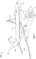
- FIG. 1 illustrates an example aircraft 100 in which the examples disclosed herein may be implemented.
- the aircraft 100 of the illustrated example includes a tail section 101 including a vertical fin 102 adjacent to a dorsal fairing 104, horizontal stabilizers 106, a nose section (e.g., a cockpit section) 110 and wings 112 attached to a fuselage 114.
- a tail section 101 including a vertical fin 102 adjacent to a dorsal fairing 104, horizontal stabilizers 106, a nose section (e.g., a cockpit section) 110 and wings 112 attached to a fuselage 114.
- a nose section e.g., a cockpit section
- the examples described herein may be applied to surfaces and/or features (e.g., riblets) of any of the tail section 101, the nose section 110, the stabilizers 106, the wings 112 and/or the fuselage 114, or any other exterior or outboard structure (e.g., a wing strut, an engine strut, a canard stabilizer, etc.) and/or surface of the aircraft 100.
- surfaces and/or features e.g., riblets
- a detail 118 shows a riblet applique 200 with ridges 202.
- the riblet applique 200 is placed on an aerodynamic surface 120. Additionally or alternatively, the riblet applique 200 can be placed on any of the wings 112, the stabilizers 106, the fuselage 114 or any other appropriate position of the aircraft 100.
- Arrows 122 generally indicate a direction of airflow over the aircraft 100 during flight of the aircraft 100.
- the ridges 202 and/or the riblet applique 200 are aligned (or substantially aligned) with the direction of the airflow, thereby enabling a relatively laminar airflow surround the aircraft 100 which, in turn, can reduce an overall drag coefficient of the aircraft 100 and, thus, fuel consumption of the aircraft 100.
- FIG. 2 is the aforementioned example riblet applique (e.g., a fluorosilicone riblet structure) 200 of the external surface 120 of the example aircraft 100 of FIG. 1 on which the examples disclosed herein may be implemented.
- the riblet applique 200 includes a riblet structure 201 and a support layer 308, which is described in greater detail below in connection with FIGS. 3-5 .
- the riblet structure 201 of the illustrated example is cast/molded and includes the ridges (e.g., wedges) 202, which are spaced apart from one another, and base surfaces (e.g., valleys, aircraft surfaces, etc.) 204 that space the ridges 202 apart from one another.
- the profiles of the ridges 202 are triangular (or substantially triangular), thereby defining ridges/wedges having triangular cross-sections (or substantially triangular cross-sections).
- the ridges 202 may be spaced apart at distances of 10-200 microns, for example.
- the riblet structure 201 is coupled to other layers to facilitate adhesion to external surfaces of the aircraft 100 and also to reduce long-term UV damage, as will be discussed in greater detail below in connection with FIGS. 3-5 . While the example riblet structure 201 is cast/molded in this example, the riblet structure 201 may be formed by extruding, embossing, pressing, thermo-forming, machining, etc.
- the base surfaces 204 may have ridges and/or other features/geometries that are smaller than the ridges 202. While the ridges 202 have a triangular cross-sectional profile, the ridges 202 may have any appropriate cross-sectional profile including, but not limited to, rectangular, oval-like, finned, etc.
- the riblet applique 200 and/or the riblet structure 201 is a riblet of the aircraft 100 and is used to alter the aerodynamic characteristics of the aircraft 100 by reducing an overall drag of the aircraft 100, for example, and may be located on any external surface of the aircraft 100.
- the riblet applique 200 and/or the riblet structure 201 of the illustrated example is used to reduce aerodynamic drag by controlling the turbulent boundary layers and/or preventing cross-flows associated with a turbulent boundary layer in air near an external surface of the aircraft 100, as described above in connection with FIG. 1 .
- the riblet structure 201 includes the ridges 202 and is installed on the external surface of the aircraft 100 as the riblet applique 200.
- the ridges 202 are aligned with a desired direction of airflow. This alignment allows the ridges 202 to act as small fences or guides that disrupt and reduce lateral airflow motions near the external surface to enhance in-line turbulent airflow and reduce skin friction of the external surface, thereby reducing overall drag of the aircraft 100.
- the riblet applique 200 is applied to the aircraft 100 during manufacture of or after the aircraft 100 is manufactured. In some other examples, the riblet applique 200 is not attached or installed on the external surface during or after manufacturing of the aircraft 100 but, rather, is integral with the external surface.
- the riblet applique 200 and/or the riblet structure 201 may be preformed or embedded into or on the external surface (e.g., machined or molded/cast onto a skin surface, built into a composite cured part, robotically placed, etc.) instead of being coupled (e.g., mechanically adhered) to the external surface.
- the example riblet applique 200 and/or the riblet structure 201 is shown as having triangular ridges 202, the ridges 202 may be any other appropriate shape including round, rectangular, etc.
- FIG. 3 is a detailed cross-sectional view of an example layered (e.g., multilayered) riblet construction (e.g., a riblet applique, a riblet assembly, a riblet applique structure, a riblet, a layered riblet construction, etc.) 300 in accordance with the teachings of this disclosure.
- the riblet construction 300 is shown prior to being assembled and/or adhered to at least one external surface of the aircraft 100.
- FIG. 3 is a detailed cross-sectional view of an example layered (e.g., multilayered) riblet construction (e.g., a riblet applique, a riblet assembly, a riblet applique structure, a riblet, a layered riblet construction, etc.) 300 in accordance with the teachings of this disclosure.
- the riblet construction 300 is shown prior to being assembled and/or adhered to at least one external surface of the aircraft 100.
- FIG. 3 is a detailed cross-section
- the riblet construction 300 of the illustrated example has multiple layers including a masking (e.g., an adhesive layer, a protective interface portion) 301, and a riblet elastomer 302 that can define the example riblet applique 200 and/or the riblet structure 201 of FIG. 2 .
- a polymer coating 303 is implemented between masking 301 and the riblet elastomer 302.
- the example riblet elastomer 302 includes a first fluorosilicone layer (e.g., a riblet tip structure, a clear riblet tip structure, etc.) 304, which defines a pattern of riblet tips/wedges and valleys, and may be transparent or opaque/colored, and a second fluorosilicone layer 306, which is a color layer in this and other examples, but may be transparent in other examples. In some examples, when the first fluorosilicone layer 304 is opaque or colored, second fluorosilicone layer 306 may not be implemented.
- the example riblet construction 300 further includes the aforementioned support layer (also known as a base applique) 308.
- the support layer 308 of the illustrated example includes a polymer film 310 (e.g., a UV stable polyethylene terephthalate (PET) film, a UV opaque polymer film, etc.), a polymer sub-layer 312, which is also a thermoplastic material in this and other examples, and a pressure sensitive adhesive sub-layer 314.
- a polymer film 310 e.g., a UV stable polyethylene terephthalate (PET) film, a UV opaque polymer film, etc.
- PET polyethylene terephthalate
- polymer sub-layer 312 which is also a thermoplastic material in this and other examples
- the polymer film 310 is implemented as a vacuum-plasma-treated polymer film, and includes a first surface (e.g., an upper surface, a surface adjacent or proximate the riblet elastomer 302) 320 and a second surface (e.g., a lower surface, a surface adjacent or proximate the polymer sub-layer 312) 322.
- the polymer film 310 includes UV stable material that is highly resistant to damage from UV rays (e.g., from sunlight).
- the polymer film 310 can be implemented as a UV stable PET or a UV stable Kapton material. However, any appropriate material can be implemented instead.
- the first surface 320 includes a riblet elastomer adhesion promoter 319 that is applied to facilitate adhesion of the riblet elastomer 302 to the support layer 308.
- the riblet elastomer adhesion promoter facilitates casting (e.g., direct casting) of the first fluorosilicone layer 304 and/or the second fluorosilicone layer 306 onto the support layer 308.
- the example first surface 320 is processed by a vacuum plasma treatment and growth of a relatively thin (e.g., tens of nanometers thin) metal oxide (e.g., a metal oxide layer, SiO 2 , Al 2 O 3 , etc.) 321 thereon.
- the vacuum plasma process utilizes an ionized gas that flows between power and ground electrodes to enable and/or facilitate growth of the metal oxide.
- any appropriate plasma treatment process can be implemented instead.
- the second surface 322 of the polymer film 310 includes a thermoplastic film adhesion promoter, which can be utilized for direct thermal lamination of the polymer film 310 to the polymer sub-layer 312.
- the polymer sub-layer 312 can be implemented as a thermoplastic elastomer.
- the second surface 322 includes a polyurethane laminating adhesive promoter 323 (e.g., for "wet” bonding and/or lamination of the polymer film 310 to the polymer sub-layer 312).
- a polyurethane laminating adhesive promoter 323 e.g., for "wet” bonding and/or lamination of the polymer film 310 to the polymer sub-layer 3112.
- the polymer film 310 and/or the polymer sub-layer 312 are treated for ink adhesion and/or plasma treated.
- At least one adhesive layer 309 is implemented between the polymer film 310 and the polymer sub-layer 312.
- An adhesive layer 309' can also be implemented between the second fluorosilicone layer 306 and the polymer film 310.
- an adhesive layer 309" is implemented between the polymer sub-layer 312 and the pressure sensitive adhesive sub-layer 314.
- the example adhesive layers 309, 309', 309" can be an aliphatic adhesive (e.g., aliphatic urethane, etc.), or any other appropriate type of adhesive.
- the first and second fluorosilicone layers 304, 306 are different materials (e.g., different fluorosilicone layers). However, in yet other examples, the first and second fluorosilicone layers 304, 306 may be composed of the same material. In some such examples, the first and second fluorosilicone layers 304, 306 are integral (e.g., define a single and contiguous fluorosilicone layer) and/or only the first fluorosilicone layer 304 is implemented. In particular, the first and second fluorosilicone layers 304, 306 can be molded and/or extruded as a single component and/or layer.
- first and second fluorosilicone layers 304, 306 of the illustrated example are fluorosilicone material(s)
- the first and second fluorosilicone layers 304, 306 may include any high elongation elastomer, such as epoxy, polyurethane, polyurea, polyolefin, ethylene propylene, silicone, polybutadiene, polychloroprene, chlorinated polyethylene and fluorosilicones, fluorinated polyurethanes, perfluoropolyethers, sylilated polyurethanes, or other hybrid polymers that include polyhedral oligomeric silsesquioxane, etc.
- any other appropriate material can be implemented instead.
- the riblet construction 300 also includes a removable liner 316, which is removed to expose the pressure sensitive adhesive sub-layer 314.
- the masking 301 of some examples, including the illustrated example is used to protect the riblet construction 300 and/or the first fluorosilicone layer 304 (e.g., riblet tips of the first fluorosilicone layer 304) during manufacturing, shipping and/or storage, the masking 301 is removed upon installation of the riblet construction 300 (e.g., during installation of the riblet construction 300 to a surface of an aircraft).
- the masking 301 can be an embossed polyethylene material, for example.
- the masking 301 is implemented in and/or provided from a single-piece continuous roll web tool.
- the masking 301 is rolled (e.g., via a rolling process) onto the first fluorosilicone layer 304 and/or the second fluorosilicone layer 306 to act as a protective installation surface with a relatively high lubricity, thereby enabling relatively smooth pressure across a surface of the first fluorosilicone layer 304 and/or the second fluorosilicone layer 306 when manual tools (e.g., squeegees) are used on and/or applied to the riblet construction 300 and/or any component(s) thereof.
- the aforementioned lubricity of the first fluorosilicone layer 304 prevents damage of the riblet construction 300 when the masking 301 is applied or removed from the riblet construction 300.
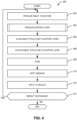
- An example method 400 begins as the example riblet construction 300 is to be produced and integrated onto a vehicle.
- the riblet construction 300 is to be produced for integration onto an aircraft to decrease a drag coefficient of the aircraft and, in turn, reduce fuel consumption of the aircraft, thereby enabling potential reductions of operating expenses pertaining to the aircraft.
- the riblet construction 300 can be applied to any appropriate other type of vehicle.
- the riblet structure 201 is produced and/or defined.
- the riblet structure 201 is produced and then subsequently placed onto a surface of an aircraft, such as the example aircraft 100 shown in FIG. 1 .
- the riblet structure 201 can be cast onto a skin surface.
- the riblet structure 201 is cast onto the support layer 308 (e.g., by accomplishing blocks 404 and 406 described below simultaneously), the adhesive layer 309, and/or the polymer film 310.
- the riblet structure 201 is cast onto the polymer film 310 and/or an associated masking layer, and then coupled to either support layer 308 (e.g., by accomplishing blocks 404 and 406 simultaneously) or onto polymer film 310.
- the support layer 308 is produced and/or defined. As will be discussed in greater detail below in connection with FIG. 5 , the support layer 308 is produced and/or defined by adding and/or coupling numerous layers. In some alternative examples, the riblet structure 201 is produced (block 402) then incorporated into production of the support layer (block 403), thereby producing a final applique (e.g., completion of block 408 below).
- the riblet structure 201 is aligned to the support layer 308.
- a first roll of the riblet structure 201 is aligned to a second roll of the support layer 308 so that the riblet structure 201 can be subsequently coupled to the support layer 308 as the first and second rolls are unrolled, for example.
- the riblet structure 201 is coupled to the support layer 308 to define the riblet construction 300 and/or the riblet applique 200.
- the riblet construction 300 is coupled to the support layer 308 via the adhesive promoter 323, for example.
- the riblet construction 300 is cured.
- the riblet construction 300 is cured in an oven (e.g., cured in an oven as the riblet construction 300 is being moved along a conveyor belt, or at ambient temperature after roll up of the multilayer riblet applique).
- the riblet elastomer 302 is cured with (e.g., concurrently with) the support layer 308.
- the protective masking 301 is applied to the riblet construction 300.
- the masking 301 is applied onto the riblet construction 300 with a continuous roll casting process.
- the masking 301 is placed on a webtool, and embossed with the negative profile of the desired riblet shape, onto which the first fluorosilicone layer 304 is cast.
- the riblet applique 200 is applied to a vehicle, such as the aircraft 100 of FIG. 1 .
- the riblet applique 200 is aligned relative to the vehicle so that the ridges 202 shown in FIG. 2 are aligned with (e.g., extend along) or substantially aligned with a direction of airflow over the vehicle.
- FIG. 5 is a flowchart representative of the example subroutine 403 of the example method 400 of FIG. 4 .
- the support layer 308 is to be produced to provide UV resistance and structural support to the riblet applique 200 and/or the riblet construction 300.
- the polymer film 310 is coupled to the polymer sub-layer 312.
- the polymer film 310 is implemented as a vacuum-plasma-treated polymer film.
- the polymer film 310 is coupled to the polymer sub-layer 312 via the aliphatic adhesive 309'.
- the polymer sub-layer 312 is coupled to the pressure-sensitive adhesive sub-layer 314.
- the polymer sub-layer 312 is coupled to the pressure-sensitive adhesive sub-layer 314 with an aliphatic adhesive 309".
- the removable liner 316 is coupled to the adhesive sub-layer 314 and the process ends/returns.
- the adhesive sub-layer 314 is incorporated with the adhesive sub-layer 314.
- the removable liner 316 can be subsequently removed from the support layer 308 when the riblet construction 300 is applied to a vehicle, for example.
- example systems, methods, apparatus, and articles of manufacture have been disclosed that enable cost-effective and easy to produce riblet structures.
- Examples disclosed herein enable a robust layering of multilayer riblet applique that is highly resistant to separation (e.g., internal layer separation, delamination, etc.), as well as UV damage.
- Some examples disclosed herein implement adhesives with aliphatic urethane to exploit a notably higher UV resistance of aliphatic chemistry. For examples that implement this adhesive between multiple or all layers, significant increases in UV resistance can be experienced.
- examples disclosed herein can utilize a single polymer layer, for example, that exhibits both UV resistance to damage and, importantly, UV opacity to minimize transmission of UV into laminate layers below.
- PEEK polyether ether ketone
- A, B, and/or C refers to any combination or subset of A, B, C such as (1) A alone, (2) B alone, (3) C alone, (4) A with B, (5) A with C, (6) B with C, or (7) A with B and with C.
- the phrase "at least one of A and B" is intended to refer to examples including any of (1) at least one A, (2) at least one B, or (3) at least one A and at least one B.
- the phrase "at least one of A or B" is intended to refer to examples including any of (1) at least one A, (2) at least one B, or (3) at least one A and at least one B.
- the phrase "at least one of A and B" is intended to refer to examples including any of (1) at least one A, (2) at least one B, or (3) at least one A and at least one B.
- the phrase "at least one of A or B" is intended to refer to examples including any of (1) at least one A, (2) at least one B, or (3) at least one A and at least one B.
- a riblet applique (200) comprises: a fluorosilicone riblet structure (201) including riblet ridges (202) and a base (204) from which the riblet ridges extend; and a support layer (308) proximate the fluorosilicone riblet structure, the support layer including: a vacuum-plasma-treated polymer film (310) having a first surface (320) and a second surface (322) opposite the first surface, and a polymer sub-layer (312) proximate the second surface of the polymer film.
- the first surface includes an elastomer adhesion promoter (319).
- the riblet applique as defined in either of the preceding two paragraphs further includes an aliphatic adhesive (309) between the vacuum-plasma-treated polymer film and the fluorosilicone riblet structure.
- the aliphatic adhesive is a first aliphatic adhesive, and further includes a second aliphatic adhesive (309") between the polymer sub-layer and a pressure sensitive adhesive sub-layer (314) of the support layer.
- the vacuum-plasma-treated polymer film includes a metal oxide layer (321).
- the riblet applique as defined in any of the preceding five paragraphs further includes a polyurethane laminating adhesive promoter (323) positioned at or proximate the second surface.
- the riblet applique as defined in any of the preceding six paragraphs further includes a masking (301) adjacent the fluorosilicone riblet structure, the masking includes an embossed polyethylene.
- the riblet applique as defined in any of the preceding seven paragraphs further includes a polymer coating (303) between the masking and the fluorosilicone riblet structure.
- the vacuum-plasma-treated polymer film includes an ultraviolet (UV) stable material.
- the vacuum-plasma-treated polymer film includes polyethylene terephthalate.
- the fluorosilicone riblet structure includes a first fluorosilicone layer (304) and a second fluorosilicone layer (306), the first and second fluorosilicone layers composed of different fluorosilicone materials.
- the fluorosilicone riblet structure is cast to the vacuum-plasma-treated polymer film.
- a method of producing a riblet applique comprises: aligning a fluorosilicone riblet structure to a support layer, the fluorosilicone riblet structure includes riblet ridges and a base from which the riblet ridges extend, the support layer includes: a vacuum-plasma-treated polymer film having a first surface and a second surface opposite the first surface, and a polymer sub-layer proximate the second surface of the polymer film; and coupling the fluorosilicone riblet structure to the support layer at the first surface.
- the method of the preceding paragraph further includes coupling the vacuum-plasma-treated polymer film to the polymer sub-layer.
- the method of either of the preceding two paragraphs further includes applying an elastomer adhesion promoter to the support layer prior to coupling the polymer sub-layer to the support layer.
- the method of any of the preceding three paragraphs further includes coupling the support layer to the elastomeric sub-layer via thermal lamination.
- the coupling the fluorosilicone riblet structure to the support layer includes applying an aliphatic adhesive to at least one of the fluorosilicone riblet structure or the support layer.
- the method of any of the preceding five paragraphs further includes curing the fluorosilicone riblet structure with the support layer.
- curing the fluorosilicone riblet structure to the support layer is performed via an oven.
- curing the fluorosilicone riblet structure to the support layer is performed at ambient temperature on a roll.
- a method of affecting aerodynamic properties of an aircraft comprises: modifying aerodynamic properties of a surface of the aircraft by applying a riblet applique to the aerodynamic surface (120) of the aircraft, the riblet applique includes: a fluorosilicone riblet structure including riblet ridges and a base from which the riblet ridges extend; and a support layer proximate the fluorosilicone riblet structure, the support layer includes: a vacuum-plasma-treated polymer film having a first surface and a second surface opposite the first surface, and a polymer sub-layer proximate the second surface of the polymer film.
- the aerodynamic surface includes a surface of a wing (112) or a horizontal stabilizer (106).
- the riblet structures are aligned relative to a direction of travel of the aircraft so that aerodynamic drag of the aircraft is reduced by preventing cross-flows associated with a turbulent boundary layer proximate the aerodynamic surface.
- applying the riblet applique to the aerodynamic surface includes aligning the riblet ridges to a direction of airflow over the aerodynamic surface.
Landscapes
- Engineering & Computer Science (AREA)
- Aviation & Aerospace Engineering (AREA)
- Laminated Bodies (AREA)
- Chemical & Material Sciences (AREA)
- Organic Chemistry (AREA)
Abstract
Description
- This disclosure relates generally to appliques and, more particularly, to multilayer riblet appliques.
- Microstructures such as riblets are typically used on an aircraft to alter flight characteristics and/or dynamics of the aircraft. In particular, the riblets are used on surfaces of a wing, a fin or a fuselage of the aircraft to reduce drag and/or a drag coefficient of the aircraft, which can result in overall fuel savings and/or reduction in carbon-dioxide emissions, etc. Riblets may also be used to provide traction (e.g., for stepping, etc.) for personnel (e.g., maintenance personnel).
- The riblets can have a multilayered construction and are typically attached to aircraft surfaces using an adhesive (e.g., adhered or applied as an applique). In particular, the riblets are multilayered for different functions including aesthetics, grounding and geometric/physical requirements (e.g., flow altering capabilities and/or durability). In known examples, it is important for riblets with a layered construction to have reliable and consistent bonding and/or curing between layers because the riblets can be exposed to high loads, as well as relatively harsh environmental conditions, associated with flight.
- Known riblet appliques sometimes include a layer of aluminum foil, which can limit or prevent UV from reaching inner layers of a riblet that are below the foil. However, incorporating foil in the riblet applique can be difficult, time consuming, and expensive. For instance, processing of the foil to obtain adequate adhesion can be expensive and require processing with a significant time. There is, therefore, a desire for a riblet applique that provides UV protection without an aluminum foil layer.
- An example riblet applique includes a fluorosilicone riblet structure including riblet ridges and a base from which the riblet ridges extend, and a support layer proximate the fluorosilicone riblet structure. The support layer includes a vacuum-plasma-treated polymer film having a first surface and a second surface opposite the first surface, and a polymer sub-layer proximate the second surface of the polymer film.
- An example support layer for use with a riblet applique includes a vacuum-plasma-treated polymer film having a first surface and a second surface opposite the first surface, the first surface to be coupled to a riblet structure including riblet ridges and a base from which the riblet ridges extend, and a polymer sub-layer proximate the second surface of the polymer film, the polymer sub-layer to be coupled to an adhesive for coupling the riblet applique to an external surface of a vehicle.
- An example method of producing a riblet applique includes aligning a fluorosilicone riblet structure to a support layer, the fluorosilicone riblet structure including riblet ridges and a base from which the riblet ridges extend. The support layer includes a vacuum-plasma-treated polymer film having a first surface and a second surface opposite the first surface, and a polymer sub-layer proximate the second surface of the polymer film. The method further includes coupling the fluorosilicone riblet structure to the support layer at the first surface.
-
-
FIG. 1 illustrates an example aircraft that may be used to implement the example methods and apparatus disclosed herein. -
FIG. 2 is an example riblet microstructure from an external surface of the example aircraft ofFIG. 1 on which the examples disclosed herein may be implemented. -
FIG. 3 is a cross-sectional view of an example layered riblet construction in accordance with the teachings of this disclosure. -
FIG. 4 is a flowchart representative of an example method that may be used to implement the examples disclosed herein. -
FIG. 5 is a flowchart representative of an example subroutine of the example method ofFIG. 4 . - The figures are not to scale. Instead, the thickness of the layers or regions may be enlarged in the drawings. Although the figures show layers and regions with clean lines and boundaries, some or all of these lines and/or boundaries may be idealized. In reality, the boundaries and/or lines may be unobservable, blended, and/or irregular. In general, the same reference numbers will be used throughout the drawing(s) and accompanying written description to refer to the same or like parts. As used herein, unless otherwise stated, the term "above" describes the relationship of two parts relative to Earth. A first part is above a second part, if the second part is between Earth and the first part. Likewise, as used herein, a first part is "below" a second part when the first part is closer to the Earth than the second part. As noted above, a first part can be above or below a second part with one or more of: other parts therebetween, without other parts therebetween, with the first and second parts touching, or without the first and second parts being in direct contact with one another. As used in this patent, stating that any part is in any way on (e.g., positioned on, located on, disposed on, or formed on, etc.) another part, indicates that the referenced part is either in contact with the other part, or that the referenced part is above the other part with one or more intermediate part(s) located therebetween. As used herein, connection references (e.g., attached, coupled, connected, and joined) may include intermediate members between the elements referenced by the connection reference and/or relative movement between those elements unless otherwise indicated. As such, connection references do not necessarily infer that two elements are directly connected and/or in fixed relation to each other. As used herein, stating that any part is in "contact" with another part is defined to mean that there is no intermediate part between the two parts.
- Unless specifically stated otherwise, descriptors such as "first," "second," "third," etc., are used herein without imputing or otherwise indicating any meaning of priority, physical order, arrangement in a list, and/or ordering in any way, but are merely used as labels and/or arbitrary names to distinguish elements for ease of understanding the disclosed examples. In some examples, the descriptor "first" may be used to refer to an element in the detailed description, while the same element may be referred to in a claim with a different descriptor such as "second" or "third." In such instances, it should be understood that such descriptors are used merely for identifying those elements distinctly that might, for example, otherwise share a same name. As used herein, "approximately" and "about" refer to dimensions that may not be exact due to manufacturing tolerances and/or other real-world imperfections.
- Multilayer riblet appliques are disclosed herein.
- An applique, as the term is used herein, may be considered to be a flexible sheet of material that is manufactured prior to application to an aircraft. The applique may be deformable so as to be able to conform to compound-contoured surfaces of an aircraft upon application.
- Microstructures such as riblets, for example, are typically used on aerodynamic surfaces of an aircraft to alter and/or improve flight characteristics to reduce an overall drag of the aircraft and, thus, may result in in overall fuel savings and/or reduction in carbon-dioxide emissions, etc. In particular, the riblets are used on surfaces of a wing, a fin or a fuselage of the aircraft to reduce drag and/or a drag coefficient of the aircraft, which can result in overall fuel savings and/or reduction in carbon-dioxide emissions, etc. These riblets, for example, can have a multilayered construction and are typically attached to aircraft surfaces using an adhesive (e.g., as a multilayered applique). The riblets are multilayered for different functions including aesthetics, grounding and/or geometric/physical requirements (e.g., flow altering capabilities and/or durability) and can be subject to significant loading (e.g., wind loads, etc.) during flight, for example. Thus, effective interlayer bonding and/or assembly of this multilayered construction can greatly reduce and/or prevent delamination of the riblet itself or separation of the riblet from an aircraft surface (e.g., a surface of an aircraft fuselage) due to significant loads encountered during flight, for example.
- Examples disclosed herein enable cost-effective multilayered riblet applique structures (e.g., multilayered riblet structures) that are resistant to delamination and/or separation of layers. In particular, examples disclosed herein are related to layering constructions that very effectively bind together layers of riblet applique structures, thereby enabling a relatively long service life thereof. Further, examples disclosed herein are highly resistant to ultraviolet (UV) damage and, thus, can last with a relatively significant amount of UV exposure.
- According to examples disclosed herein, a riblet applique includes a fluorosilicone riblet structure having riblet ridges and a base from which the riblet ridges extend, and a support layer proximate or adjacent the fluorosilicone riblet structure. In turn, the support layer includes a vacuum-plasma-treated polymer film with a first surface and a second surface opposite the first surface (e.g., the first and second surfaces of the plasma-treated polymer film are diametrically opposed at different thicknesses of the polymer film). The support layer also includes a polymer sub-layer proximate or adjacent the second surface of the polymer film. As a result, examples disclosed herein are cost-effective while enabling significant resistance to damage (e.g., delamination) and/or long-term degradation.
- In some examples, the riblet elastomer is directly cast onto a carrier film that is pre-embossed with the negative shape of the desired riblet geometry; then while still uncured, the fluorosilicone is laminated to the first surface of the polymer film alone or as the upper surface of the multilayer applique base. In some examples, the carrier film is retained as a protective masking layer through subsequent fabrication of the full riblet applique and during application onto the aircraft. In some examples, the embossed carrier film is created from polymers exhibiting ready release after installation, such as polyethylene or fluoropolymers, for example. In some examples, the first surface of the support polymer film includes a riblet elastomer adhesion promoter to facilitate bonding of the polymer film to the riblet elastomer. In some examples, adhesion-promoting treatments include vacuum plasma, as well as chemical or coating treatments. In some examples, the fluorosilicone riblet structure includes a UV stable polymer support film, such as polyethylene terephthalate formulated for UV stability, for example. Additionally, in some examples, an aliphatic urethane adhesive is implemented between the second surface of the vacuum-plasma-treated polymer film and the polymer sub-layer, and is cured after coupling the vacuum-plasma-treated polymer film and the polymer sub-layer.
- As used herein, the terms "riblet," "riblet construction" or "riblet structure" may refer to geometric features, dimensions and/or distances between geometric features (e.g., periodic distances, heights and/or widths, etc.) that define, form, couple and/or support riblets. Therefore, the terms "riblet," "riblet construction" or "riblet structure" may refer to any of a riblet layer, a riblet assembly and/or a multilayered riblet construction, etc.
-
FIG. 1 illustrates anexample aircraft 100 in which the examples disclosed herein may be implemented. Theaircraft 100 of the illustrated example includes atail section 101 including avertical fin 102 adjacent to adorsal fairing 104,horizontal stabilizers 106, a nose section (e.g., a cockpit section) 110 andwings 112 attached to afuselage 114. The examples described herein may be applied to surfaces and/or features (e.g., riblets) of any of thetail section 101, thenose section 110, thestabilizers 106, thewings 112 and/or thefuselage 114, or any other exterior or outboard structure (e.g., a wing strut, an engine strut, a canard stabilizer, etc.) and/or surface of theaircraft 100. - As can be seen in the illustrated example, a
detail 118 shows ariblet applique 200 withridges 202. In this and other examples, theriblet applique 200 is placed on anaerodynamic surface 120. Additionally or alternatively, theriblet applique 200 can be placed on any of thewings 112, thestabilizers 106, thefuselage 114 or any other appropriate position of theaircraft 100.Arrows 122 generally indicate a direction of airflow over theaircraft 100 during flight of theaircraft 100. In this example, theridges 202 and/or theriblet applique 200 are aligned (or substantially aligned) with the direction of the airflow, thereby enabling a relatively laminar airflow surround theaircraft 100 which, in turn, can reduce an overall drag coefficient of theaircraft 100 and, thus, fuel consumption of theaircraft 100. -
FIG. 2 is the aforementioned example riblet applique (e.g., a fluorosilicone riblet structure) 200 of theexternal surface 120 of theexample aircraft 100 ofFIG. 1 on which the examples disclosed herein may be implemented. Theriblet applique 200 includes ariblet structure 201 and asupport layer 308, which is described in greater detail below in connection withFIGS. 3-5 . Theriblet structure 201 of the illustrated example is cast/molded and includes the ridges (e.g., wedges) 202, which are spaced apart from one another, and base surfaces (e.g., valleys, aircraft surfaces, etc.) 204 that space theridges 202 apart from one another. In this and other examples, the profiles of theridges 202 are triangular (or substantially triangular), thereby defining ridges/wedges having triangular cross-sections (or substantially triangular cross-sections). Theridges 202 may be spaced apart at distances of 10-200 microns, for example. Theriblet structure 201 is coupled to other layers to facilitate adhesion to external surfaces of theaircraft 100 and also to reduce long-term UV damage, as will be discussed in greater detail below in connection withFIGS. 3-5 . While theexample riblet structure 201 is cast/molded in this example, theriblet structure 201 may be formed by extruding, embossing, pressing, thermo-forming, machining, etc. In other examples, the base surfaces 204 may have ridges and/or other features/geometries that are smaller than theridges 202. While theridges 202 have a triangular cross-sectional profile, theridges 202 may have any appropriate cross-sectional profile including, but not limited to, rectangular, oval-like, finned, etc. - In this and other examples, the
riblet applique 200 and/or theriblet structure 201 is a riblet of theaircraft 100 and is used to alter the aerodynamic characteristics of theaircraft 100 by reducing an overall drag of theaircraft 100, for example, and may be located on any external surface of theaircraft 100. Theriblet applique 200 and/or theriblet structure 201 of the illustrated example is used to reduce aerodynamic drag by controlling the turbulent boundary layers and/or preventing cross-flows associated with a turbulent boundary layer in air near an external surface of theaircraft 100, as described above in connection withFIG. 1 . In particular, theriblet structure 201 includes theridges 202 and is installed on the external surface of theaircraft 100 as theriblet applique 200. Further, theridges 202 are aligned with a desired direction of airflow. This alignment allows theridges 202 to act as small fences or guides that disrupt and reduce lateral airflow motions near the external surface to enhance in-line turbulent airflow and reduce skin friction of the external surface, thereby reducing overall drag of theaircraft 100. In this and other examples, theriblet applique 200 is applied to theaircraft 100 during manufacture of or after theaircraft 100 is manufactured. In some other examples, theriblet applique 200 is not attached or installed on the external surface during or after manufacturing of theaircraft 100 but, rather, is integral with the external surface. For example, theriblet applique 200 and/or theriblet structure 201 may be preformed or embedded into or on the external surface (e.g., machined or molded/cast onto a skin surface, built into a composite cured part, robotically placed, etc.) instead of being coupled (e.g., mechanically adhered) to the external surface. While theexample riblet applique 200 and/or theriblet structure 201 is shown as havingtriangular ridges 202, theridges 202 may be any other appropriate shape including round, rectangular, etc. -
FIG. 3 is a detailed cross-sectional view of an example layered (e.g., multilayered) riblet construction (e.g., a riblet applique, a riblet assembly, a riblet applique structure, a riblet, a layered riblet construction, etc.) 300 in accordance with the teachings of this disclosure. In the view ofFIG. 3 , theriblet construction 300 is shown prior to being assembled and/or adhered to at least one external surface of theaircraft 100. As can also be seen inFIG. 3 , theriblet construction 300 of the illustrated example has multiple layers including a masking (e.g., an adhesive layer, a protective interface portion) 301, and ariblet elastomer 302 that can define theexample riblet applique 200 and/or theriblet structure 201 ofFIG. 2 . In some examples, apolymer coating 303 is implemented between masking 301 and theriblet elastomer 302. Theexample riblet elastomer 302 includes a first fluorosilicone layer (e.g., a riblet tip structure, a clear riblet tip structure, etc.) 304, which defines a pattern of riblet tips/wedges and valleys, and may be transparent or opaque/colored, and asecond fluorosilicone layer 306, which is a color layer in this and other examples, but may be transparent in other examples. In some examples, when thefirst fluorosilicone layer 304 is opaque or colored,second fluorosilicone layer 306 may not be implemented. Theexample riblet construction 300 further includes the aforementioned support layer (also known as a base applique) 308. Thesupport layer 308 of the illustrated example includes a polymer film 310 (e.g., a UV stable polyethylene terephthalate (PET) film, a UV opaque polymer film, etc.), apolymer sub-layer 312, which is also a thermoplastic material in this and other examples, and a pressure sensitiveadhesive sub-layer 314. - In this and other examples, the
polymer film 310 is implemented as a vacuum-plasma-treated polymer film, and includes a first surface (e.g., an upper surface, a surface adjacent or proximate the riblet elastomer 302) 320 and a second surface (e.g., a lower surface, a surface adjacent or proximate the polymer sub-layer 312) 322. Moreover, thepolymer film 310 includes UV stable material that is highly resistant to damage from UV rays (e.g., from sunlight). For example, thepolymer film 310 can be implemented as a UV stable PET or a UV stable Kapton material. However, any appropriate material can be implemented instead. - According to the illustrated example, the
first surface 320 includes a ribletelastomer adhesion promoter 319 that is applied to facilitate adhesion of theriblet elastomer 302 to thesupport layer 308. In some examples, the riblet elastomer adhesion promoter facilitates casting (e.g., direct casting) of thefirst fluorosilicone layer 304 and/or thesecond fluorosilicone layer 306 onto thesupport layer 308. Further, the examplefirst surface 320 is processed by a vacuum plasma treatment and growth of a relatively thin (e.g., tens of nanometers thin) metal oxide (e.g., a metal oxide layer, SiO2, Al2O3, etc.) 321 thereon. In this and other examples, the vacuum plasma process utilizes an ionized gas that flows between power and ground electrodes to enable and/or facilitate growth of the metal oxide. However, any appropriate plasma treatment process can be implemented instead. According to some examples, including the illustrated example, thesecond surface 322 of thepolymer film 310 includes a thermoplastic film adhesion promoter, which can be utilized for direct thermal lamination of thepolymer film 310 to thepolymer sub-layer 312. For example, thepolymer sub-layer 312 can be implemented as a thermoplastic elastomer. Additionally or alternatively, thesecond surface 322 includes a polyurethane laminating adhesive promoter 323 (e.g., for "wet" bonding and/or lamination of thepolymer film 310 to the polymer sub-layer 312). In some examples, thepolymer film 310 and/or thepolymer sub-layer 312 are treated for ink adhesion and/or plasma treated. - In some examples, at least one
adhesive layer 309 is implemented between thepolymer film 310 and thepolymer sub-layer 312. An adhesive layer 309' can also be implemented between thesecond fluorosilicone layer 306 and thepolymer film 310. Additionally or alternatively, anadhesive layer 309" is implemented between thepolymer sub-layer 312 and the pressure sensitiveadhesive sub-layer 314. The exampleadhesive layers - In this and other examples, the first and second fluorosilicone layers 304, 306 are different materials (e.g., different fluorosilicone layers). However, in yet other examples, the first and second fluorosilicone layers 304, 306 may be composed of the same material. In some such examples, the first and second fluorosilicone layers 304, 306 are integral (e.g., define a single and contiguous fluorosilicone layer) and/or only the
first fluorosilicone layer 304 is implemented. In particular, the first and second fluorosilicone layers 304, 306 can be molded and/or extruded as a single component and/or layer. - While the first and second fluorosilicone layers 304, 306 of the illustrated example are fluorosilicone material(s), in other examples, the first and second fluorosilicone layers 304, 306 may include any high elongation elastomer, such as epoxy, polyurethane, polyurea, polyolefin, ethylene propylene, silicone, polybutadiene, polychloroprene, chlorinated polyethylene and fluorosilicones, fluorinated polyurethanes, perfluoropolyethers, sylilated polyurethanes, or other hybrid polymers that include polyhedral oligomeric silsesquioxane, etc. However, any other appropriate material can be implemented instead.
- To couple the
riblet construction 300 to an aircraft and/or vehicle surface, theriblet construction 300 also includes aremovable liner 316, which is removed to expose the pressure sensitiveadhesive sub-layer 314. Further, while the masking 301 of some examples, including the illustrated example, is used to protect theriblet construction 300 and/or the first fluorosilicone layer 304 (e.g., riblet tips of the first fluorosilicone layer 304) during manufacturing, shipping and/or storage, the masking 301 is removed upon installation of the riblet construction 300 (e.g., during installation of theriblet construction 300 to a surface of an aircraft). The masking 301 can be an embossed polyethylene material, for example. - In this and other examples, the masking 301 is implemented in and/or provided from a single-piece continuous roll web tool. In some examples, the masking 301 is rolled (e.g., via a rolling process) onto the
first fluorosilicone layer 304 and/or thesecond fluorosilicone layer 306 to act as a protective installation surface with a relatively high lubricity, thereby enabling relatively smooth pressure across a surface of thefirst fluorosilicone layer 304 and/or thesecond fluorosilicone layer 306 when manual tools (e.g., squeegees) are used on and/or applied to theriblet construction 300 and/or any component(s) thereof. In this and other examples, the aforementioned lubricity of thefirst fluorosilicone layer 304 prevents damage of theriblet construction 300 when the masking 301 is applied or removed from theriblet construction 300. - An
example method 400 begins as theexample riblet construction 300 is to be produced and integrated onto a vehicle. In particular, theriblet construction 300 is to be produced for integration onto an aircraft to decrease a drag coefficient of the aircraft and, in turn, reduce fuel consumption of the aircraft, thereby enabling potential reductions of operating expenses pertaining to the aircraft. However, theriblet construction 300 can be applied to any appropriate other type of vehicle. - At
block 402, theriblet structure 201 is produced and/or defined. In this and other examples, theriblet structure 201 is produced and then subsequently placed onto a surface of an aircraft, such as theexample aircraft 100 shown inFIG. 1 . In some other examples, theriblet structure 201 can be cast onto a skin surface. In some examples, theriblet structure 201 is cast onto the support layer 308 (e.g., by accomplishingblocks adhesive layer 309, and/or thepolymer film 310. Additionally or alternatively, theriblet structure 201 is cast onto thepolymer film 310 and/or an associated masking layer, and then coupled to either support layer 308 (e.g., by accomplishingblocks polymer film 310. - At
block 403, thesupport layer 308 is produced and/or defined. As will be discussed in greater detail below in connection withFIG. 5 , thesupport layer 308 is produced and/or defined by adding and/or coupling numerous layers. In some alternative examples, theriblet structure 201 is produced (block 402) then incorporated into production of the support layer (block 403), thereby producing a final applique (e.g., completion ofblock 408 below). - At
block 404, theriblet structure 201 is aligned to thesupport layer 308. For example, a first roll of theriblet structure 201 is aligned to a second roll of thesupport layer 308 so that theriblet structure 201 can be subsequently coupled to thesupport layer 308 as the first and second rolls are unrolled, for example. - At
block 406, in some examples, theriblet structure 201 is coupled to thesupport layer 308 to define theriblet construction 300 and/or theriblet applique 200. In some such examples, theriblet construction 300 is coupled to thesupport layer 308 via theadhesive promoter 323, for example. - At
block 408, in some examples, theriblet construction 300 is cured. In some such examples, theriblet construction 300 is cured in an oven (e.g., cured in an oven as theriblet construction 300 is being moved along a conveyor belt, or at ambient temperature after roll up of the multilayer riblet applique). Additionally or alternatively, theriblet elastomer 302 is cured with (e.g., concurrently with) thesupport layer 308. - At
block 410, if a webtool embossed with the negative profile of the desired riblet shape was not used to create theriblet elastomer 302 and retained after casting theriblet elastomer 302, theprotective masking 301 is applied to theriblet construction 300. In this and other examples, the masking 301 is applied onto theriblet construction 300 with a continuous roll casting process. In some examples, the masking 301 is placed on a webtool, and embossed with the negative profile of the desired riblet shape, onto which thefirst fluorosilicone layer 304 is cast. - At
block 412, theriblet applique 200 is applied to a vehicle, such as theaircraft 100 ofFIG. 1 . In this and other examples, theriblet applique 200 is aligned relative to the vehicle so that theridges 202 shown inFIG. 2 are aligned with (e.g., extend along) or substantially aligned with a direction of airflow over the vehicle. - At
block 414, it is determined whether to repeat the process. If the process is to be repeated (block 414), control of the process returns to block 402. Otherwise, the process ends. The determination may be based on whether additional riblet structures are to be produced, whether additional riblets structures are to be provided to a vehicle and/or whether additional vehicles are to be applied with theriblet applique 200. -
FIG. 5 is a flowchart representative of theexample subroutine 403 of theexample method 400 ofFIG. 4 . In this and other examples, thesupport layer 308 is to be produced to provide UV resistance and structural support to theriblet applique 200 and/or theriblet construction 300. - At
block 502, thepolymer film 310 is coupled to thepolymer sub-layer 312. In some examples, including the illustrated example, thepolymer film 310 is implemented as a vacuum-plasma-treated polymer film. In some examples, thepolymer film 310 is coupled to thepolymer sub-layer 312 via the aliphatic adhesive 309'. - At
block 504, thepolymer sub-layer 312 is coupled to the pressure-sensitiveadhesive sub-layer 314. In some examples, thepolymer sub-layer 312 is coupled to the pressure-sensitiveadhesive sub-layer 314 with analiphatic adhesive 309". - At
block 506, in some other examples, theremovable liner 316 is coupled to theadhesive sub-layer 314 and the process ends/returns. In this and other examples, theadhesive sub-layer 314 is incorporated with theadhesive sub-layer 314. Theremovable liner 316 can be subsequently removed from thesupport layer 308 when theriblet construction 300 is applied to a vehicle, for example. - Further examples and combinations thereof include the following:
- Example 1 includes a riblet applique comprising a fluorosilicone riblet structure including riblet ridges and a base from which the riblet ridges extend, and a support layer proximate the fluorosilicone riblet structure, the support layer including a vacuum-plasma-treated polymer film having a first surface and a second surface opposite the first surface, and a polymer sub-layer proximate the second surface of the polymer film.
- Example 2 includes the riblet applique as defined in example 1, wherein the first surface includes an elastomer adhesion promoter.
- Example 3 includes the riblet applique as defined in any of examples 1 or 2, further including an aliphatic adhesive between the vacuum-plasma-treated polymer film and the fluorosilicone riblet structure.
- Example 4 includes the riblet applique as defined in example 3, wherein the aliphatic adhesive is a first aliphatic adhesive, and further including a second aliphatic adhesive between the polymer sub-layer and a pressure sensitive adhesive sub-layer of the support layer.
- Example 5 includes the riblet applique as defined in any of examples 1 to 4, wherein the vacuum-plasma-treated polymer film includes a metal oxide layer.
- Example 6 includes the riblet applique as defined in any of examples 1 to 5, further including a polyurethane laminating adhesive promoter positioned at or proximate the second surface.
- Example 7 includes the riblet applique as defined in any of examples 1 to 6, further including a masking adjacent the fluorosilicone riblet structure, the masking including an embossed polyethylene.
- Example 8 includes the riblet applique as defined in example 7, further including a polymer coating between the masking and the fluorosilicone riblet structure.
- Example 9 includes the riblet applique as defined in any of examples 1 to 8, wherein the vacuum-plasma-treated polymer film includes an ultraviolet (UV) stable material.
- Example 10 includes the riblet applique as defined in example 9, wherein the vacuum-plasma-treated polymer film includes polyethylene terephthalate.
- Example 11 includes the riblet applique as defined in any of examples 1 to 10, wherein the fluorosilicone riblet structure includes a first fluorosilicone layer and a second fluorosilicone layer, the first and second fluorosilicone layers composed of different fluorosilicone materials.
- Example 12 includes the riblet applique as defined in any of examples 1 to 11, wherein the fluorosilicone riblet structure is cast to the vacuum-plasma-treated polymer film.
- Example 13 includes a method of producing a riblet applique, the method comprising aligning a fluorosilicone riblet structure to a support layer, the fluorosilicone riblet structure including riblet ridges and a base from which the riblet ridges extend, the support layer including a vacuum-plasma-treated polymer film having a first surface and a second surface opposite the first surface, and a polymer sub-layer proximate the second surface of the polymer film, and coupling the fluorosilicone riblet structure to the support layer at the first surface.
- Example 14 includes the method as defined in example 13, further including coupling the vacuum-plasma-treated polymer film to the polymer sub-layer.
- Example 15 includes the method as defined in example 14, further including applying an elastomer adhesion promoter to the support layer prior to coupling the elastomeric sub-layer to the support layer.
- Example 16 includes the method as defined in example 15, further including coupling the support layer to the polymer sub-layer or the elastomeric sub-layer via thermal lamination.
- Example 17 includes the method as defined in any of examples 14 to 16, wherein the coupling the fluorosilicone riblet structure to the support layer includes applying an aliphatic adhesive to at least one of the fluorosilicone riblet structure or the support layer.
- Example 18 includes the method as defined in any of examples 13 to 17, further including curing the fluorosilicone riblet structure with the support layer.
- Example 19 includes the method as defined in example 18, wherein curing the fluorosilicone riblet structure to the support layer is performed via an oven.
- Example 20 includes the method as defined in example 18, wherein curing the fluorosilicone riblet structure to the support layer is performed at ambient temperature on a roll.
- Example 21 includes a method of affecting aerodynamic properties of an aircraft, comprising modifying aerodynamic properties of a surface of the aircraft by applying a riblet applique to the aerodynamic surface of the aircraft, the riblet applique including a fluorosilicone riblet structure including riblet ridges and a base from which the riblet ridges extend, and a support layer proximate the fluorosilicone riblet structure, the support layer including a vacuum-plasma-treated polymer film having a first surface and a second surface opposite the first surface, and a polymer sub-layer proximate the second surface of the polymer film.
- Example 22 includes the method as defined in example 21, wherein the aerodynamic surface includes a surface of a wing, or a horizontal stabilizer.
- Example 23 includes the method as defined in example 21, wherein the riblet structures are aligned relative to a direction of travel of the aircraft so that aerodynamic drag of the aircraft is reduced by preventing cross-flows associated with a turbulent boundary layer proximate the aerodynamic surface.
- Example 24 includes the method as defined in example 21, wherein applying the riblet applique to the aerodynamic surface includes aligning the riblet ridges to a direction of airflow over the aerodynamic surface.
- Example 25 includes a support layer for use with a riblet applique, the support layer comprising a vacuum-plasma-treated polymer film having a first surface and a second surface opposite the first surface, the first surface to be coupled to a riblet structure including riblet ridges and a base from which the riblet ridges extend, and a polymer sub-layer coupled to the second surface of the polymer film, the polymer sub-layer to be coupled to an adhesive for coupling the riblet applique to an external surface of a vehicle.
- Example 26 includes the support layer as defined in example 25, wherein the polymer film is coupled to the polymer sub-layer via an aliphatic adhesive.
- From the foregoing, it will be appreciated that example systems, methods, apparatus, and articles of manufacture have been disclosed that enable cost-effective and easy to produce riblet structures. Examples disclosed herein enable a robust layering of multilayer riblet applique that is highly resistant to separation (e.g., internal layer separation, delamination, etc.), as well as UV damage. Some examples disclosed herein implement adhesives with aliphatic urethane to exploit a notably higher UV resistance of aliphatic chemistry. For examples that implement this adhesive between multiple or all layers, significant increases in UV resistance can be experienced. By replacing UV-screening typically accomplished by foil and reducing and/or eliminating use of polyether ether ketone (PEEK) film, examples disclosed herein can utilize a single polymer layer, for example, that exhibits both UV resistance to damage and, importantly, UV opacity to minimize transmission of UV into laminate layers below.
- Including" and "comprising" (and all forms and tenses thereof) are used herein to be open ended terms. Thus, whenever a claim employs any form of "include" or "comprise" (e.g., comprises, includes, comprising, including, having, etc.) as a preamble or within a claim recitation of any kind, it is to be understood that additional elements, terms, etc., may be present without falling outside the scope of the corresponding claim or recitation. As used herein, when the phrase "at least" is used as the transition term in, for example, a preamble of a claim, it is open-ended in the same manner as the term "comprising" and "including" are open ended. The term "and/or" when used, for example, in a form such as A, B, and/or C refers to any combination or subset of A, B, C such as (1) A alone, (2) B alone, (3) C alone, (4) A with B, (5) A with C, (6) B with C, or (7) A with B and with C. As used herein in the context of describing structures, components, items, objects and/or things, the phrase "at least one of A and B" is intended to refer to examples including any of (1) at least one A, (2) at least one B, or (3) at least one A and at least one B. Similarly, as used herein in the context of describing structures, components, items, objects and/or things, the phrase "at least one of A or B" is intended to refer to examples including any of (1) at least one A, (2) at least one B, or (3) at least one A and at least one B. As used herein in the context of describing the performance or execution of processes, instructions, actions, activities and/or steps, the phrase "at least one of A and B" is intended to refer to examples including any of (1) at least one A, (2) at least one B, or (3) at least one A and at least one B. Similarly, as used herein in the context of describing the performance or execution of processes, instructions, actions, activities and/or steps, the phrase "at least one of A or B" is intended to refer to examples including any of (1) at least one A, (2) at least one B, or (3) at least one A and at least one B.
- Further illustrative and non-exclusive examples according to the disclosure are described in the following paragraphs:
In an example according to the present disclosure, a riblet applique (200) comprises: a fluorosilicone riblet structure (201) including riblet ridges (202) and a base (204) from which the riblet ridges extend; and a support layer (308) proximate the fluorosilicone riblet structure, the support layer including: a vacuum-plasma-treated polymer film (310) having a first surface (320) and a second surface (322) opposite the first surface, and a polymer sub-layer (312) proximate the second surface of the polymer film. - Optionally, in the riblet applique as defined in the preceding paragraph, the first surface includes an elastomer adhesion promoter (319).
- Optionally, the riblet applique as defined in either of the preceding two paragraphs further includes an aliphatic adhesive (309) between the vacuum-plasma-treated polymer film and the fluorosilicone riblet structure.
- Optionally, in the riblet applique as defined in any of the preceding three paragraphs, the aliphatic adhesive is a first aliphatic adhesive, and further includes a second aliphatic adhesive (309") between the polymer sub-layer and a pressure sensitive adhesive sub-layer (314) of the support layer.
- Optionally, in the riblet applique as defined in any of the preceding four paragraphs, the vacuum-plasma-treated polymer film includes a metal oxide layer (321).
- Optionally, the riblet applique as defined in any of the preceding five paragraphs further includes a polyurethane laminating adhesive promoter (323) positioned at or proximate the second surface.
- Optionally, the riblet applique as defined in any of the preceding six paragraphs further includes a masking (301) adjacent the fluorosilicone riblet structure, the masking includes an embossed polyethylene.
- Optionally, the riblet applique as defined in any of the preceding seven paragraphs further includes a polymer coating (303) between the masking and the fluorosilicone riblet structure.
- Optionally, in the riblet applique as defined in any of the preceding eight paragraphs, the vacuum-plasma-treated polymer film includes an ultraviolet (UV) stable material.
- Optionally, in the riblet applique as defined in any of the preceding nine paragraphs, the vacuum-plasma-treated polymer film includes polyethylene terephthalate.
- Optionally, in the riblet applique as defined in any of the preceding ten paragraphs, the fluorosilicone riblet structure includes a first fluorosilicone layer (304) and a second fluorosilicone layer (306), the first and second fluorosilicone layers composed of different fluorosilicone materials.
- Optionally, in the riblet applique as defined in any of the preceding eleven paragraphs, the fluorosilicone riblet structure is cast to the vacuum-plasma-treated polymer film.
- In another example according to the present disclosure, a method of producing a riblet applique, the method comprises: aligning a fluorosilicone riblet structure to a support layer, the fluorosilicone riblet structure includes riblet ridges and a base from which the riblet ridges extend, the support layer includes: a vacuum-plasma-treated polymer film having a first surface and a second surface opposite the first surface, and a polymer sub-layer proximate the second surface of the polymer film; and coupling the fluorosilicone riblet structure to the support layer at the first surface.
- Optionally, the method of the preceding paragraph further includes coupling the vacuum-plasma-treated polymer film to the polymer sub-layer.
- Optionally, the method of either of the preceding two paragraphs further includes applying an elastomer adhesion promoter to the support layer prior to coupling the polymer sub-layer to the support layer.
- Optionally, the method of any of the preceding three paragraphs further includes coupling the support layer to the elastomeric sub-layer via thermal lamination.
- Optionally, in the method of any of the preceding four paragraphs, the coupling the fluorosilicone riblet structure to the support layer includes applying an aliphatic adhesive to at least one of the fluorosilicone riblet structure or the support layer.
- Optionally, the method of any of the preceding five paragraphs further includes curing the fluorosilicone riblet structure with the support layer.
- Optionally, in the method of any of the preceding six paragraphs, curing the fluorosilicone riblet structure to the support layer is performed via an oven.
- Optionally, in the method of any of the preceding seven paragraphs, curing the fluorosilicone riblet structure to the support layer is performed at ambient temperature on a roll.
- In another example according to the present disclosure, a method of affecting aerodynamic properties of an aircraft, comprises: modifying aerodynamic properties of a surface of the aircraft by applying a riblet applique to the aerodynamic surface (120) of the aircraft, the riblet applique includes: a fluorosilicone riblet structure including riblet ridges and a base from which the riblet ridges extend; and a support layer proximate the fluorosilicone riblet structure, the support layer includes: a vacuum-plasma-treated polymer film having a first surface and a second surface opposite the first surface, and a polymer sub-layer proximate the second surface of the polymer film.
- Optionally, in the method of the preceding paragraph, the aerodynamic surface includes a surface of a wing (112) or a horizontal stabilizer (106).
- Optionally, in the method of either of the preceding two paragraphs, the riblet structures are aligned relative to a direction of travel of the aircraft so that aerodynamic drag of the aircraft is reduced by preventing cross-flows associated with a turbulent boundary layer proximate the aerodynamic surface.
- Optionally, in the method of any of the preceding three paragraphs, applying the riblet applique to the aerodynamic surface includes aligning the riblet ridges to a direction of airflow over the aerodynamic surface.
- As used herein, singular references (e.g., "a", "an", "first", "second", etc.) do not exclude a plurality. The term "a" or "an" object, as used herein, refers to one or more of that object. The terms "a" (or "an"), "one or more", and "at least one" are used interchangeably herein. Furthermore, although individually listed, a plurality of means, elements or method actions may be implemented by, e.g., the same entity or object. Additionally, although individual features may be included in different examples or claims, these may possibly be combined, and the inclusion in different examples or claims does not imply that a combination of features is not feasible and/or advantageous.
- Although certain example systems, methods, apparatus, and articles of manufacture have been disclosed herein, the scope of coverage of this patent is not limited thereto. On the contrary, this patent covers all systems, methods, apparatus, and articles of manufacture fairly falling within the scope of the claims of this patent.
Claims (15)
- A riblet applique (200) comprising:a fluorosilicone riblet structure (201) including riblet ridges (202) and a base (204) from which the riblet ridges extend; anda support layer (308) proximate the fluorosilicone riblet structure, the support layer including:a vacuum-plasma-treated polymer film (310) having a first surface (320) and a second surface (322) opposite the first surface, anda polymer sub-layer (312) proximate the second surface of the polymer film.
- The riblet applique as defined in claim 1, wherein the first surface includes an elastomer adhesion promoter (319).
- The riblet applique as defined in claim 1 or 2, further including an aliphatic adhesive (309) between the vacuum-plasma-treated polymer film and the fluorosilicone riblet structure; and, optionally,
wherein the aliphatic adhesive is a first aliphatic adhesive, and further including a second aliphatic adhesive (309") between the polymer sub-layer and a pressure sensitive adhesive sub-layer (314) of the support layer. - The riblet applique as defined in any one of claims 1-3, wherein the vacuum-plasma-treated polymer film includes a metal oxide layer (321).
- The riblet applique as defined in any one of claims 1-4, further including a polyurethane laminating adhesive promoter (323) positioned at or proximate the second surface.
- The riblet applique as defined in any one of claims 1-5, further including:a masking (301) adjacent the fluorosilicone riblet structure, the masking including an embossed polyethylene; and, optionally,a polymer coating (303) between the masking and the fluorosilicone riblet structure.
- The riblet applique as defined in any one of claim 1-6, wherein:the vacuum-plasma-treated polymer film includes an ultraviolet (UV) stable material; and, optionally,the vacuum-plasma-treated polymer film includes polyethylene terephthalate.
- The riblet applique as defined in any one of claims 1-7, wherein:the fluorosilicone riblet structure is cast to the vacuum-plasma-treated polymer film; and/orthe fluorosilicone riblet structure includes a first fluorosilicone layer (304) and a second fluorosilicone layer (306), the first and second fluorosilicone layers composed of different fluorosilicone materials.
- An aircraft including the riblet applique as defined in any one of claims 1-8.
- A method of producing a riblet applique, the method comprising:aligning a fluorosilicone riblet structure to a support layer, the fluorosilicone riblet structure including riblet ridges and a base from which the riblet ridges extend, the support layer including:a vacuum-plasma-treated polymer film having a first surface and a second surface opposite the first surface, anda polymer sub-layer proximate the second surface of the polymer film; andcoupling the fluorosilicone riblet structure to the support layer at the first surface.
- The method as defined in claim 10, further including coupling the vacuum-plasma-treated polymer film to the polymer sub-layer.
- The method as defined in claim 11, further including:applying an elastomer adhesion promoter to the support layer prior to coupling the polymer sub-layer to the support layer; and, optionally,coupling the support layer to the polymer sub-layer via thermal lamination.
- The method as defined in claim 11 or 12, wherein the coupling the fluorosilicone riblet structure to the support layer includes applying an aliphatic adhesive to the fluorosilicone riblet structure and/or the support layer.
- The method as defined in any one of claims 10-13, further including curing the fluorosilicone riblet structure with the support layer, optionally by curing the fluorosilicone riblet structure to the support layer via an oven or at ambient temperature on a roll.
- A method of affecting aerodynamic properties of an aircraft, comprising:modifying aerodynamic properties of a surface of the aircraft by applying the riblet applique as defined in any of claims 1 to 8 to the aerodynamic surface of the aircraft; and, optionally,wherein applying the riblet applique to the aerodynamic surface includes aligning the riblet ridges to a direction of airflow over the aerodynamic surface.
Applications Claiming Priority (1)
| Application Number | Priority Date | Filing Date | Title |
|---|---|---|---|
| US17/463,778 US11987021B2 (en) | 2021-09-01 | 2021-09-01 | Multilayer riblet appliques |
Publications (1)
| Publication Number | Publication Date |
|---|---|
| EP4144520A1 true EP4144520A1 (en) | 2023-03-08 |
Family
ID=82115611
Family Applications (1)
| Application Number | Title | Priority Date | Filing Date |
|---|---|---|---|
| EP22179577.6A Pending EP4144520A1 (en) | 2021-09-01 | 2022-06-17 | Multilayer riblet appliques |
Country Status (3)
| Country | Link |
|---|---|
| US (1) | US11987021B2 (en) |
| EP (1) | EP4144520A1 (en) |
| CN (1) | CN115725246A (en) |
Cited By (1)
| Publication number | Priority date | Publication date | Assignee | Title |
|---|---|---|---|---|
| DE102023119923A1 (en) | 2023-07-27 | 2025-01-30 | Lufthansa Technik Aktiengesellschaft | Method for the application of fluid dynamic functional film on complex flow bodies |
Families Citing this family (2)
| Publication number | Priority date | Publication date | Assignee | Title |
|---|---|---|---|---|
| GB2703006A (en) * | 2024-11-29 | 2026-07-08 | Airbus Operations Ltd | Split riblet |
| CN121293937B (en) * | 2025-12-11 | 2026-03-17 | 南通纳科达聚氨酯科技有限公司 | High-viscosity drag reduction film based on microstructure and preparation method thereof |
Citations (4)
| Publication number | Priority date | Publication date | Assignee | Title |
|---|---|---|---|---|
| US20060051592A1 (en) * | 2003-09-30 | 2006-03-09 | Rawlings Diane C | Wide area lightning diverter overlay |
| US20100187361A1 (en) * | 2009-01-29 | 2010-07-29 | The Boeing Company | Amorphous metal riblets |
| US20100282909A1 (en) * | 2009-01-29 | 2010-11-11 | The Boeing Company | Elastomeric riblets |
| EP3266581A1 (en) * | 2016-07-08 | 2018-01-10 | The Boeing Company | Multilayer riblet applique and methods of producing the same |
Family Cites Families (105)
| Publication number | Priority date | Publication date | Assignee | Title |
|---|---|---|---|---|
| US4093487A (en) | 1976-11-15 | 1978-06-06 | Dayco Corporation | Method of continuously making a printing blanket construction |
| US4706910A (en) | 1984-12-27 | 1987-11-17 | The United States Of America As Represented By The Administrator Of The National Aeronautics And Space Administration | Combined riblet and lebu drag reduction system |
| US4986496A (en) | 1985-05-31 | 1991-01-22 | Minnesota Mining And Manufacturing | Drag reduction article |
| US5133516A (en) | 1985-05-31 | 1992-07-28 | Minnesota Mining And Manufacturing Co. | Drag reduction article |
| US4994053A (en) | 1985-06-26 | 1991-02-19 | Kimberly-Clark Corporation | Composite article having discrete particulate areas formed therein |
| DE3522943A1 (en) | 1985-06-27 | 1987-01-08 | Messerschmitt Boelkow Blohm | DEVICE FOR REDUCING TURBULENT FRICTION RESISTANCE IN AIR, SPACE AND WATER VEHICLES |
| US4650138A (en) | 1985-09-30 | 1987-03-17 | Internorth, Inc. | Cascaded micro-groove aerodynamic drag reducer |
| US4932612A (en) | 1986-02-25 | 1990-06-12 | Blackwelder Ron F | Method and apparatus for reducing turbulent skin friction |
| GB8706554D0 (en) | 1987-03-19 | 1987-04-23 | Rolls Royce Plc | Boundary layer devices |
| US4930729A (en) | 1986-05-22 | 1990-06-05 | Rolls-Royce Plc | Control of fluid flow |
| US4897146A (en) | 1988-01-28 | 1990-01-30 | General Electric Company | Apparatus and method for fabricating structural panels having corrugated core structures and panel formed therewith |
| US5133519A (en) | 1989-04-21 | 1992-07-28 | Board Of Trustees Operating Michigan State University | Drag reduction method and surface |
| US5054412A (en) | 1989-10-31 | 1991-10-08 | The United States Of America As Represented By The Administrator Of The National Aeronautics And Space Administration | Hydrodynamic skin-friction reduction |
| US5445095A (en) | 1990-08-14 | 1995-08-29 | The United States Of America As Represented By The Administrator Of The National Aeronautics And Space Administration | Polymer/riblet combination for hydrodynamic skin friction reduction |
| DE9316009U1 (en) | 1993-10-20 | 1994-01-13 | Moser, Josef, 85435 Erding | Surface of a fluid-flowed body |
| US5505543A (en) | 1994-01-21 | 1996-04-09 | The Boeing Company | Emissivity measurement apparatus and method |
| US5456785A (en) | 1994-05-17 | 1995-10-10 | Venable; Jesse S. | Composite roofing product and method and apparatus for making a composite roofing product |
| US5520717A (en) | 1995-06-07 | 1996-05-28 | The Boeing Company | Isolating nanophase amorphous magnetic metals |
| US6982794B1 (en) | 1995-06-07 | 2006-01-03 | The Boeing Company | Directional reflectometer |
| US5637873A (en) | 1995-06-07 | 1997-06-10 | The Boeing Company | Directional reflectometer for measuring optical bidirectional reflectance |
| US5766764A (en) | 1996-06-04 | 1998-06-16 | The Boeing Company | Nanoscale amorphous magnetic metals |
| US5766306A (en) | 1996-06-04 | 1998-06-16 | The Boeing Company | Continuous process for making nanoscale amorphous magnetic metals |
| DE19650439C1 (en) | 1996-12-05 | 1998-03-12 | Deutsch Zentr Luft & Raumfahrt | Ribbed surface for wall subjected to turbulent airflow |
| US6191248B1 (en) | 1996-12-19 | 2001-02-20 | The Boeing Company | Coating |
| US5874167A (en) | 1996-12-19 | 1999-02-23 | The Boeing Company | High efficiency metal pigments |
| EP0946664A4 (en) | 1996-12-20 | 2001-12-19 | Boeing Co | Appliques providing corrosion protection |
| US6376063B1 (en) | 1998-06-15 | 2002-04-23 | The Boeing Company | Making particulates of controlled dimensions by electroplating |
| US6520926B2 (en) | 1999-02-24 | 2003-02-18 | Lohmann Rauscher, Inc. | Compression support sleeve |
| US6524675B1 (en) | 1999-05-13 | 2003-02-25 | 3M Innovative Properties Company | Adhesive-back articles |
| US6475616B1 (en) | 1999-11-30 | 2002-11-05 | 3M Innovative Properties Company | Paint replacement appliques |
| US6345791B1 (en) | 2000-04-13 | 2002-02-12 | Lockheed Martin Corporation | Streamwise variable height riblets for reducing skin friction drag of surfaces |
| GB0108740D0 (en) | 2001-04-06 | 2001-05-30 | Bae Systems Plc | Turbulent flow drag reduction |
| US20050003146A1 (en) | 2001-06-21 | 2005-01-06 | Bernd Spath | Body with improved surface properties |
| PL204021B1 (en) | 2001-11-02 | 2009-12-31 | Cnt Spo & Lstrok Ka Z Ogranicz | Superhydrophobous coating |
| US7703179B2 (en) | 2001-11-09 | 2010-04-27 | 3M Innovative Properties Company | Microreplicated surface |
| EP1316419A3 (en) | 2001-11-30 | 2004-01-28 | General Electric Company | Weatherable multilayer articles and method for their preparation |
| DE10217111A1 (en) | 2002-04-17 | 2003-11-06 | Roehm Gmbh | Solid with microstructured surface |
| AU2003272194A1 (en) | 2002-04-26 | 2004-02-23 | Board Of Regents | Methods for reducing the viscous drag on a surface and drag reducing device |
| GB0213551D0 (en) | 2002-06-13 | 2002-07-24 | Univ Nottingham | Controlling boundary layer fluid flow |
| US6958207B1 (en) | 2002-12-07 | 2005-10-25 | Niyaz Khusnatdinov | Method for producing large area antireflective microtextured surfaces |
| US7070850B2 (en) | 2002-12-31 | 2006-07-04 | 3M Innovative Properties Company | Drag reduction article and method of use |
| KR20040061658A (en) | 2002-12-31 | 2004-07-07 | 삼성전자주식회사 | Hybrid achromatic optical lens and manufacturing method thereof |
| US20050008821A1 (en) | 2003-07-07 | 2005-01-13 | Pricone Robert M. | Process and apparatus for fabricating precise microstructures and polymeric molds for making same |
| US7224529B2 (en) | 2003-09-09 | 2007-05-29 | 3M Innovative Properties Company | Microreplicated article |
| ES2428032T3 (en) | 2003-09-30 | 2013-11-05 | The Boeing Company | Protective wall covering and use thereof |
| DE10346124B4 (en) | 2003-10-01 | 2005-12-01 | Fraunhofer-Gesellschaft zur Förderung der angewandten Forschung e.V. | Tool and method for producing a microstructured surface and use of a tool and the object produced therewith |
| US7252869B2 (en) | 2003-10-30 | 2007-08-07 | Niyaz Khusnatdinov | Microtextured antireflective surfaces with reduced diffraction intensity |
| US7510149B2 (en) | 2004-08-02 | 2009-03-31 | Lockheed Martin Corporation | System and method to control flowfield vortices with micro-jet arrays |
| US20070060026A1 (en) | 2005-09-09 | 2007-03-15 | Chien-Min Sung | Methods of bonding superabrasive particles in an organic matrix |
| BRPI0608701A2 (en) | 2005-03-09 | 2010-01-19 | 3M Innovative Properties Co | micro-replicated article and method of making a micro-replicated article |
| MX2007010994A (en) | 2005-03-09 | 2007-11-07 | 3M Innovative Properties Co | Apparatus and method for making microreplicated article. |
| WO2007030952A1 (en) | 2005-09-12 | 2007-03-22 | Perlen Converting Ag | Method for the application of a structured coating upon a smooth surface |
| US7544407B1 (en) | 2005-09-17 | 2009-06-09 | The Boeing Company | Pressure sensitive adhesive suitable for aircraft exterior applications |
| US7757591B2 (en) | 2005-10-19 | 2010-07-20 | 3M Innovative Properties Company | Aligned multi-diamond cutting tool assembly for creating microreplication tools |
| US7445409B2 (en) | 2005-10-19 | 2008-11-04 | 3M Innovative Properties Company | Cutting tool assembly including diamond cutting tips at half-pitch spacing for land feature creation |
| US7755670B2 (en) | 2005-10-24 | 2010-07-13 | Nikon Corporation | Tone-conversion device for image, program, electronic camera, and tone-conversion method |
| US8292226B2 (en) | 2005-11-15 | 2012-10-23 | The Boeing Company | Weight-optimizing internally pressurized composite-body aircraft fuselages having near-elliptical cross sections |
| US8113469B2 (en) | 2006-02-21 | 2012-02-14 | University Of Alabama | Passive micro-roughness array for drag modification |
| WO2008108881A2 (en) | 2006-09-08 | 2008-09-12 | Steven Sullivan | Method and apparatus for mitigating trailing vortex wakes of lifting or thrust generating bodies |
| US7525785B2 (en) | 2006-12-14 | 2009-04-28 | The Boeing Company | Lightning strike protection method and apparatus |
| US7864501B2 (en) | 2006-12-14 | 2011-01-04 | The Boeing Company | Electrical connects for charge distribution applique |
| US7678997B2 (en) | 2006-12-19 | 2010-03-16 | The Boeing Company | Large area circuitry using appliqués |
| WO2008121418A1 (en) | 2007-03-30 | 2008-10-09 | The University Of Alabama | A passive drag modification system |
| EP2031424B1 (en) | 2007-08-28 | 2011-03-09 | Nissan Motor Co., Ltd. | Antireflective structure and antireflective moulded body |
| US20130062004A1 (en) | 2007-12-12 | 2013-03-14 | The Boeing Company | Aerodynamic surfaces having drag-reducing riblets and method of fabricating the same |
| US20140023837A1 (en) | 2007-12-13 | 2014-01-23 | The Boeing Company | Aircraft structures bonded with adhesive including magnetostrictive material |
| US8343298B2 (en) | 2007-12-13 | 2013-01-01 | The Boeing Company | Aircraft structures bonded with adhesive including magnetostrictive material |
| US8286909B2 (en) | 2008-02-08 | 2012-10-16 | Stratocomm Corporation | Boundary layer propulsion airship with related system and method |
| CN102138009B (en) | 2008-08-05 | 2014-05-28 | 美铝公司 | Metal sheets and plates having friction-reducing textured surfaces and methods of manufacturing same |
| DE102008042237B4 (en) | 2008-09-19 | 2010-07-15 | Airbus Deutschland Gmbh | Metallic coating |
| US20110274875A1 (en) | 2008-11-21 | 2011-11-10 | The University Of Alabama | Passive drag modification system |
| US8684310B2 (en) | 2009-01-29 | 2014-04-01 | The Boeing Company | Rigid tipped riblets |
| US8668166B2 (en) | 2009-01-29 | 2014-03-11 | The Boeing Company | Shape memory riblets |
| US8220754B2 (en) | 2009-06-03 | 2012-07-17 | Lockheed Martin Corporation | Plasma enhanced riblet |
| US8870124B2 (en) | 2009-07-10 | 2014-10-28 | Peter Ireland | Application of elastomeric vortex generators |
| US8413928B2 (en) | 2009-09-25 | 2013-04-09 | The Boeing Company | Structurally designed aerodynamic riblets |
| US8733702B1 (en) | 2009-12-02 | 2014-05-27 | The Boeing Company | Reduced solar absorptivity applique |
| CA2786836C (en) | 2010-01-14 | 2019-01-22 | Saab Ab | An aerodynamic surface with improved properties |
| US20110186685A1 (en) | 2010-02-02 | 2011-08-04 | The Boeing Company | Thin-Film Composite Having Drag-Reducing Riblets and Method of Making the Same |
| EP2570013B1 (en) | 2010-05-12 | 2019-07-10 | Parker-Hannifin Corporation | Low force deflection and corrosion resistant emi gasket |
| DE102010031227A1 (en) | 2010-07-12 | 2012-01-12 | Fraunhofer-Gesellschaft zur Förderung der angewandten Forschung e.V. | Device for testing microstructuring quality |
| GB201012737D0 (en) | 2010-07-29 | 2010-09-15 | Airbus Operations Ltd | Improvements to aircraft refuel system piping |
| EP2799150B1 (en) | 2013-05-02 | 2016-04-27 | Hexagon Technology Center GmbH | Graphical application system |
| WO2012082668A2 (en) | 2010-12-13 | 2012-06-21 | 3M Innovative Properties Company | Patterned film and articles made therefrom |
| US8460779B2 (en) | 2011-03-30 | 2013-06-11 | General Electric Company | Microstructures for reducing noise of a fluid dynamic structure |
| DE102011106763A1 (en) | 2011-07-05 | 2013-01-10 | Eads Deutschland Gmbh | A method of manufacturing a surface of a reduced airflow resistance component and a reduced airflow resistance component |
| DE102011114832A1 (en) | 2011-10-05 | 2013-04-11 | Eads Deutschland Gmbh | RIBBON FILM AND METHOD FOR THE PRODUCTION THEREOF |
| WO2013134657A1 (en) | 2012-03-08 | 2013-09-12 | The University Of Alabama | A passive drag modification system |
| US20150037542A1 (en) | 2012-03-29 | 2015-02-05 | Microgreen Polymers Inc. | Composite Material That Includes Microcellular Plastic, and Related Systems and Methods |
| US8875511B2 (en) | 2012-03-30 | 2014-11-04 | Larry C. Simpson | Geothermal wind system |
| FI20126040A7 (en) | 2012-10-05 | 2014-04-06 | Iscent Oy | A method for producing micro- or nanostructures in polymeric film materials |
| US10011916B2 (en) | 2012-10-19 | 2018-07-03 | Ut-Battelle, Llc | Superhydrophobic anodized metals and method of making same |
| US20140116597A1 (en) | 2012-11-01 | 2014-05-01 | The Boeing Company | Methods and apparatus for heating a material |
| US20140238646A1 (en) | 2013-02-25 | 2014-08-28 | Alcatel-Lucent Ireland Ltd. | Sloped hierarchically-structured surface designs for enhanced condensation heat transfer |
| DE102013102164A1 (en) | 2013-03-05 | 2014-09-11 | Airbus Operations Gmbh | A method of coating a surface of an aircraft and an aircraft coated therewith |
| US20140272237A1 (en) | 2013-03-15 | 2014-09-18 | Prc-Desoto International, Inc. | Strippable film assembly and coating for drag reduction |
| US20140363637A1 (en) | 2013-06-06 | 2014-12-11 | The Boeing Company | Heating Layer for Film Removal |
| DE102013013817A1 (en) | 2013-08-22 | 2015-02-26 | Airbus Defence and Space GmbH | Structural component with a riblet surface |
| US9994301B2 (en) | 2013-11-18 | 2018-06-12 | Rohr, Inc. | Virtual aerodynamic surface systems |
| US20160243586A1 (en) | 2014-08-01 | 2016-08-25 | The Boeing Company | Drag reduction riblets integrated in a paint layer |
| US10059435B2 (en) | 2014-12-04 | 2018-08-28 | Parker-Hannifin Corporation | Low drag skin heat exchanger |
| FR3029813B1 (en) | 2014-12-16 | 2019-07-19 | Airbus Operations (S.A.S.) | METHOD FOR MANUFACTURING MICROSTRUCTURE COATING |
| US9751618B2 (en) | 2015-05-06 | 2017-09-05 | The Boeing Company | Optical effects for aerodynamic microstructures |
| US9868135B2 (en) | 2015-05-06 | 2018-01-16 | The Boeing Company | Aerodynamic microstructures having sub-microstructures |
| US9714083B2 (en) | 2015-05-06 | 2017-07-25 | The Boeing Company | Color applications for aerodynamic microstructures |
-
2021
- 2021-09-01 US US17/463,778 patent/US11987021B2/en active Active
-
2022
- 2022-06-17 EP EP22179577.6A patent/EP4144520A1/en active Pending
- 2022-09-01 CN CN202211063347.1A patent/CN115725246A/en active Pending
Patent Citations (4)
| Publication number | Priority date | Publication date | Assignee | Title |
|---|---|---|---|---|
| US20060051592A1 (en) * | 2003-09-30 | 2006-03-09 | Rawlings Diane C | Wide area lightning diverter overlay |
| US20100187361A1 (en) * | 2009-01-29 | 2010-07-29 | The Boeing Company | Amorphous metal riblets |
| US20100282909A1 (en) * | 2009-01-29 | 2010-11-11 | The Boeing Company | Elastomeric riblets |
| EP3266581A1 (en) * | 2016-07-08 | 2018-01-10 | The Boeing Company | Multilayer riblet applique and methods of producing the same |
Cited By (1)
| Publication number | Priority date | Publication date | Assignee | Title |
|---|---|---|---|---|
| DE102023119923A1 (en) | 2023-07-27 | 2025-01-30 | Lufthansa Technik Aktiengesellschaft | Method for the application of fluid dynamic functional film on complex flow bodies |
Also Published As
| Publication number | Publication date |
|---|---|
| US20230063783A1 (en) | 2023-03-02 |
| US11987021B2 (en) | 2024-05-21 |
| CN115725246A (en) | 2023-03-03 |
Similar Documents
| Publication | Publication Date | Title |
|---|---|---|
| US11987021B2 (en) | Multilayer riblet appliques | |
| EP2641733B1 (en) | Elastomeric riblets | |
| EP3266581B1 (en) | Multilayer riblet applique and methods of producing the same | |
| CA2771393C (en) | Structurally designed aerodynamic riblets | |
| CA2878764C (en) | Fabricating an array of rigid tipped riblets | |
| US8715824B2 (en) | Applique | |
| US20130062004A1 (en) | Aerodynamic surfaces having drag-reducing riblets and method of fabricating the same | |
| US10226915B1 (en) | Systems of forming a skin for a composite structure | |
| KR101779275B1 (en) | Strippable film assembly and coating for drag reduction | |
| CA2858540A1 (en) | Method of applying surface riblets to an aerodynamic surface | |
| US12083714B2 (en) | Methods and apparatus for tooling in layered structures for increased joint performance |
Legal Events
| Date | Code | Title | Description |
|---|---|---|---|
| PUAI | Public reference made under article 153(3) epc to a published international application that has entered the european phase |
Free format text: ORIGINAL CODE: 0009012 |
|
| STAA | Information on the status of an ep patent application or granted ep patent |
Free format text: STATUS: THE APPLICATION HAS BEEN PUBLISHED |
|
| AK | Designated contracting states |
Kind code of ref document: A1 Designated state(s): AL AT BE BG CH CY CZ DE DK EE ES FI FR GB GR HR HU IE IS IT LI LT LU LV MC MK MT NL NO PL PT RO RS SE SI SK SM TR |
|
| RAP3 | Party data changed (applicant data changed or rights of an application transferred) |
Owner name: THE BOEING COMPANY |
|
| STAA | Information on the status of an ep patent application or granted ep patent |
Free format text: STATUS: REQUEST FOR EXAMINATION WAS MADE |
|
| 17P | Request for examination filed |
Effective date: 20230830 |
|
| RBV | Designated contracting states (corrected) |
Designated state(s): AL AT BE BG CH CY CZ DE DK EE ES FI FR GB GR HR HU IE IS IT LI LT LU LV MC MK MT NL NO PL PT RO RS SE SI SK SM TR |
|
| STAA | Information on the status of an ep patent application or granted ep patent |
Free format text: STATUS: EXAMINATION IS IN PROGRESS |
|
| 17Q | First examination report despatched |
Effective date: 20250729 |