EP4144400A1 - Dual-chamber syringe with dual-lumen intravenous set - Google Patents
Dual-chamber syringe with dual-lumen intravenous set Download PDFInfo
- Publication number
- EP4144400A1 EP4144400A1 EP22202447.3A EP22202447A EP4144400A1 EP 4144400 A1 EP4144400 A1 EP 4144400A1 EP 22202447 A EP22202447 A EP 22202447A EP 4144400 A1 EP4144400 A1 EP 4144400A1
- Authority
- EP
- European Patent Office
- Prior art keywords
- primary
- port
- lumen
- valve
- dual
- Prior art date
- Legal status (The legal status is an assumption and is not a legal conclusion. Google has not performed a legal analysis and makes no representation as to the accuracy of the status listed.)
- Pending
Links
Images





Classifications
-
- A—HUMAN NECESSITIES
- A61—MEDICAL OR VETERINARY SCIENCE; HYGIENE
- A61M—DEVICES FOR INTRODUCING MEDIA INTO, OR ONTO, THE BODY; DEVICES FOR TRANSDUCING BODY MEDIA OR FOR TAKING MEDIA FROM THE BODY; DEVICES FOR PRODUCING OR ENDING SLEEP OR STUPOR
- A61M5/00—Devices for bringing media into the body in a subcutaneous, intra-vascular or intramuscular way; Accessories therefor, e.g. filling or cleaning devices, arm-rests
- A61M5/178—Syringes
- A61M5/19—Syringes having more than one chamber, e.g. including a manifold coupling two parallelly aligned syringes through separate channels to a common discharge assembly
-
- A—HUMAN NECESSITIES
- A61—MEDICAL OR VETERINARY SCIENCE; HYGIENE
- A61M—DEVICES FOR INTRODUCING MEDIA INTO, OR ONTO, THE BODY; DEVICES FOR TRANSDUCING BODY MEDIA OR FOR TAKING MEDIA FROM THE BODY; DEVICES FOR PRODUCING OR ENDING SLEEP OR STUPOR
- A61M5/00—Devices for bringing media into the body in a subcutaneous, intra-vascular or intramuscular way; Accessories therefor, e.g. filling or cleaning devices, arm-rests
- A61M5/178—Syringes
- A61M5/20—Automatic syringes, e.g. with automatically actuated piston rod, with automatic needle injection, filling automatically
-
- A—HUMAN NECESSITIES
- A61—MEDICAL OR VETERINARY SCIENCE; HYGIENE
- A61M—DEVICES FOR INTRODUCING MEDIA INTO, OR ONTO, THE BODY; DEVICES FOR TRANSDUCING BODY MEDIA OR FOR TAKING MEDIA FROM THE BODY; DEVICES FOR PRODUCING OR ENDING SLEEP OR STUPOR
- A61M5/00—Devices for bringing media into the body in a subcutaneous, intra-vascular or intramuscular way; Accessories therefor, e.g. filling or cleaning devices, arm-rests
- A61M5/178—Syringes
- A61M5/20—Automatic syringes, e.g. with automatically actuated piston rod, with automatic needle injection, filling automatically
- A61M5/2066—Automatic syringes, e.g. with automatically actuated piston rod, with automatic needle injection, filling automatically comprising means for injection of two or more media, e.g. by mixing
-
- A—HUMAN NECESSITIES
- A61—MEDICAL OR VETERINARY SCIENCE; HYGIENE
- A61M—DEVICES FOR INTRODUCING MEDIA INTO, OR ONTO, THE BODY; DEVICES FOR TRANSDUCING BODY MEDIA OR FOR TAKING MEDIA FROM THE BODY; DEVICES FOR PRODUCING OR ENDING SLEEP OR STUPOR
- A61M5/00—Devices for bringing media into the body in a subcutaneous, intra-vascular or intramuscular way; Accessories therefor, e.g. filling or cleaning devices, arm-rests
- A61M5/178—Syringes
- A61M5/24—Ampoule syringes, i.e. syringes with needle for use in combination with replaceable ampoules or carpules, e.g. automatic
- A61M5/2448—Ampoule syringes, i.e. syringes with needle for use in combination with replaceable ampoules or carpules, e.g. automatic comprising means for injection of two or more media, e.g. by mixing
-
- A—HUMAN NECESSITIES
- A61—MEDICAL OR VETERINARY SCIENCE; HYGIENE
- A61M—DEVICES FOR INTRODUCING MEDIA INTO, OR ONTO, THE BODY; DEVICES FOR TRANSDUCING BODY MEDIA OR FOR TAKING MEDIA FROM THE BODY; DEVICES FOR PRODUCING OR ENDING SLEEP OR STUPOR
- A61M5/00—Devices for bringing media into the body in a subcutaneous, intra-vascular or intramuscular way; Accessories therefor, e.g. filling or cleaning devices, arm-rests
- A61M5/178—Syringes
- A61M5/28—Syringe ampoules or carpules, i.e. ampoules or carpules provided with a needle
- A61M5/284—Syringe ampoules or carpules, i.e. ampoules or carpules provided with a needle comprising means for injection of two or more media, e.g. by mixing
-
- A—HUMAN NECESSITIES
- A61—MEDICAL OR VETERINARY SCIENCE; HYGIENE
- A61M—DEVICES FOR INTRODUCING MEDIA INTO, OR ONTO, THE BODY; DEVICES FOR TRANSDUCING BODY MEDIA OR FOR TAKING MEDIA FROM THE BODY; DEVICES FOR PRODUCING OR ENDING SLEEP OR STUPOR
- A61M5/00—Devices for bringing media into the body in a subcutaneous, intra-vascular or intramuscular way; Accessories therefor, e.g. filling or cleaning devices, arm-rests
- A61M5/178—Syringes
- A61M2005/1787—Syringes for sequential delivery of fluids, e.g. first medicament and then flushing liquid
-
- A—HUMAN NECESSITIES
- A61—MEDICAL OR VETERINARY SCIENCE; HYGIENE
- A61M—DEVICES FOR INTRODUCING MEDIA INTO, OR ONTO, THE BODY; DEVICES FOR TRANSDUCING BODY MEDIA OR FOR TAKING MEDIA FROM THE BODY; DEVICES FOR PRODUCING OR ENDING SLEEP OR STUPOR
- A61M5/00—Devices for bringing media into the body in a subcutaneous, intra-vascular or intramuscular way; Accessories therefor, e.g. filling or cleaning devices, arm-rests
- A61M5/178—Syringes
- A61M5/20—Automatic syringes, e.g. with automatically actuated piston rod, with automatic needle injection, filling automatically
- A61M2005/2006—Having specific accessories
-
- A—HUMAN NECESSITIES
- A61—MEDICAL OR VETERINARY SCIENCE; HYGIENE
- A61M—DEVICES FOR INTRODUCING MEDIA INTO, OR ONTO, THE BODY; DEVICES FOR TRANSDUCING BODY MEDIA OR FOR TAKING MEDIA FROM THE BODY; DEVICES FOR PRODUCING OR ENDING SLEEP OR STUPOR
- A61M5/00—Devices for bringing media into the body in a subcutaneous, intra-vascular or intramuscular way; Accessories therefor, e.g. filling or cleaning devices, arm-rests
- A61M5/178—Syringes
- A61M5/31—Details
- A61M5/3129—Syringe barrels
- A61M2005/3132—Syringe barrels having flow passages for injection agents at the distal end of the barrel to bypass a sealing stopper after its displacement to this end due to internal pressure increase
-
- A—HUMAN NECESSITIES
- A61—MEDICAL OR VETERINARY SCIENCE; HYGIENE
- A61M—DEVICES FOR INTRODUCING MEDIA INTO, OR ONTO, THE BODY; DEVICES FOR TRANSDUCING BODY MEDIA OR FOR TAKING MEDIA FROM THE BODY; DEVICES FOR PRODUCING OR ENDING SLEEP OR STUPOR
- A61M39/00—Tubes, tube connectors, tube couplings, valves, access sites or the like, specially adapted for medical use
- A61M39/08—Tubes; Storage means specially adapted therefor
- A61M2039/082—Multi-lumen tubes
-
- A—HUMAN NECESSITIES
- A61—MEDICAL OR VETERINARY SCIENCE; HYGIENE
- A61M—DEVICES FOR INTRODUCING MEDIA INTO, OR ONTO, THE BODY; DEVICES FOR TRANSDUCING BODY MEDIA OR FOR TAKING MEDIA FROM THE BODY; DEVICES FOR PRODUCING OR ENDING SLEEP OR STUPOR
- A61M39/00—Tubes, tube connectors, tube couplings, valves, access sites or the like, specially adapted for medical use
- A61M39/22—Valves or arrangement of valves
- A61M39/24—Check- or non-return valves
- A61M2039/242—Check- or non-return valves designed to open when a predetermined pressure or flow rate has been reached, e.g. check valve actuated by fluid
-
- A—HUMAN NECESSITIES
- A61—MEDICAL OR VETERINARY SCIENCE; HYGIENE
- A61M—DEVICES FOR INTRODUCING MEDIA INTO, OR ONTO, THE BODY; DEVICES FOR TRANSDUCING BODY MEDIA OR FOR TAKING MEDIA FROM THE BODY; DEVICES FOR PRODUCING OR ENDING SLEEP OR STUPOR
- A61M39/00—Tubes, tube connectors, tube couplings, valves, access sites or the like, specially adapted for medical use
- A61M39/10—Tube connectors; Tube couplings
- A61M39/105—Multi-channel connectors or couplings, e.g. for connecting multi-lumen tubes
Definitions
- the delivery of medical fluids to fluid-restricted patients often includes administering the medical fluid intravenously through an intravenous (IV) set from a fluid source at low flow rates.
- IV intravenous
- Traditional practice often involves breaking the line to deliver an IV push, which can be time consuming at such low flow rates.
- Other conventional practices may involve administering a priming solution to the fluid-restricted patient via a pump before delivering the medical fluid, which may delay the medical fluid from being administered to the fluid-restricted patient in a timely fashion.
- a dual-chamber syringe includes an end wall; a primary plunger comprising a primary stopper, the primary stopper forming a primary chamber with the end wall; a secondary plunger in mechanical association with the primary plunger, the secondary plunger comprising a secondary stopper, the secondary stopper forming a secondary chamber with the primary stopper; a primary nozzle extending from the end wall, the primary nozzle in fluid communication with the primary chamber; and a secondary nozzle extending from the end wall, the secondary nozzle in fluid communication with the secondary chamber.
- a multi-lumen intravenous (IV) set includes an adapter comprising a primary duct and a secondary duct; a valve housing comprising a housing port and a housing passage; a primary lumen in fluid communication with the primary duct and the housing port; a secondary lumen in fluid communication with the secondary duct and the housing port; and a valve disposed in the valve housing, the valve comprising a cracking pressure, wherein the valve is configured to prevent fluid flow from the housing port to the housing passage when pressure against the valve is less than the cracking pressure, and wherein the valve is configured to allow fluid flow from the housing port to the housing passage when pressure against the valve is greater than the cracking pressure.
- a fluid delivery system includes a dual-chamber syringe comprising, an end wall; a primary plunger comprising a primary stopper, the primary stopper forming a primary chamber with the end wall; a secondary plunger in mechanical association with the primary plunger, the secondary plunger comprising a secondary stopper, the secondary stopper forming a secondary chamber with the primary stopper; a primary nozzle extending from the end wall, the primary nozzle in fluid communication with the primary chamber; a secondary nozzle extending from the end wall, the secondary nozzle in fluid communication with the secondary chamber; and a multi-lumen intravenous set comprising, an adapter comprising a primary port and a secondary port, the primary port fluidly coupled to the primary nozzle and the secondary port fluidly coupled to the secondary nozzle; a valve housing comprising a housing port and a housing passage; a primary lumen in fluid communication with a primary duct disposed in the adapter and in fluid communication with the housing port; a secondary lumen in fluid communication with
- a phrase such as "an aspect” does not imply that such aspect is essential to the subject technology or that such aspect applies to all configurations of the subject technology.
- a disclosure relating to an aspect may apply to all configurations, or one or more configurations.
- An aspect may provide one or more examples of the disclosure.
- a phrase such as “an aspect” may refer to one or more aspects and vice versa.
- a phrase such as “an embodiment” does not imply that such embodiment is essential to the subject technology or that such embodiment applies to all configurations of the subject technology.
- a disclosure relating to an embodiment may apply to all embodiments, or one or more embodiments.
- An embodiment may provide one or more examples of the disclosure.
- a phrase such "an embodiment” may refer to one or more embodiments and vice versa.
- a phrase such as "a configuration” does not imply that such configuration is essential to the subject technology or that such configuration applies to all configurations of the subject technology.
- a disclosure relating to a configuration may apply to all configurations, or one or more configurations.
- a configuration may provide one or more examples of the disclosure.
- a phrase such as "a configuration” may refer to one or more configurations and vice versa.
- FIGS. 1-25 illustrate a fluid delivery system including a syringe-pump-compatible, dual-chamber syringe couplable to a dual-lumen intravenous (IV) set.
- the fluid delivery system is configured to remove priming solution from the dual-lumen IV set for reserve in the dual-chamber syringe, deliver medication at a pre-determined flow rate, and administer remaining medication residing in the dual-lumen IV set by restoring the reserved priming solution in the dual-chamber syringe to the dual-lumen IV set.
- FIGS. 1-6 illustrate an embodiment of a dual-chamber syringe 110 of a fluid delivery system 100 (shown in FIG. 19 ).
- the dual-chamber syringe 110 includes a cylindrical syringe barrel 112, an end wall 114, and a syringe collar 116.
- the end wall 114 is disposed at a first end 118 of the syringe barrel 112 while the syringe collar 116 is disposed at a second end 120 of the syringe barrel 112, which is opposite the first end 118.
- the syringe collar 116 extends radially outwardly from the syringe barrel 112 proximate the second end 120.
- the syringe barrel 112 includes a cylindrical inner chamber 122 extending between the end wall 114 and the syringe collar 116.
- a grooved channel 124 is recessed in an inner face 126 of the end wall 114.
- the inner face 126 faces the inner chamber 122 and is disposed therein.
- the channel 124 includes a notch end 128, a passage end 130, and a divot 132 disposed between the notch end 128 and the passage end 130.
- the channel 124 includes opposing beveled walls 134, which extend between the notch end 128 and the divot 132 and between the divot 132 and the passage end 130.
- the notch end 128 is in fluid communication with a notch 136, which is disposed in the syringe barrel 112 at an intersection of the syringe barrel 112 and the end wall 114 proximate the first end 118.
- the notch 136 extends axially inwardly from the end wall 114 within the inner chamber 122.
- the passage end 130 is in fluid communication with a passage 138 disposed through the end wall 114.
- the channel 124 extends along a portion of a diameter of the inner face 126.
- the notch 136, the channel 124, and the passage 138 collectively form a flushing fluid flow path of which the features and functionality will be described in more detail below.
- the dual-chamber syringe 110 also includes an internal tube 140.
- the internal tube 140 is disposed through the divot 132 and the inner face 126 of the end wall 114 and extends axially inwardly within the inner chamber 122.
- the internal tube 140 terminates within the inner chamber 122 and is offset axially inwardly with respect to the syringe collar 116.
- the internal tube 140 extends substantially centrally through the divot 132 and the inner face 126 of the end wall 114 and is disposed centrally within the inner chamber 122.
- the dual-chamber syringe 110 also includes a primary nozzle 142 and a secondary nozzle 144. Both the primary nozzle 142 and the secondary nozzle 144 extend axially outwardly from the end wall 114 and are disposed externally with respect to the inner chamber 122. In some aspects, the secondary nozzle 144 is disposed centrally on the end wall 114. The secondary nozzle 144 is coaxially aligned with the internal tube 140 and is in fluid communication with the internal tube 140. The primary nozzle 142 is radially offset on the end wall 114 from the secondary nozzle 144. The primary nozzle 142 is in fluid communication with a primary chamber 145 of the inner chamber 122 via the passage 138.
- a nozzle guide 143 also extends axially outwardly from the end wall 114 and surrounds both the primary nozzle 142 and the secondary nozzle 144 to facilitate connecting the dual-chamber syringe 110 to other medical components.
- the primary nozzle 142 and the secondary nozzle 144 are asymmetrical to prevent reversed or backwards coupling of the dual-chamber syringe 110 to the dual-lumen IV set (800).
- the primary nozzle 142 and the secondary nozzle 144 are male Luer connectors.
- the primary nozzle 142 is a male Luer connector and the secondary nozzle 144 is a needle-free connector.
- the primary nozzle 142 is a needle-free connector and the secondary nozzle 144 is a male Luer connector.
- the dual-chamber syringe 110 includes a primary plunger 146 and a secondary plunger 148.
- the primary plunger 146 is in mechanical association with the secondary plunger 148, such that both are received by the inner chamber 122 and are configured for slidable movement within the inner chamber 122.
- the primary plunger 146 includes a primary stopper 150, a primary head 152, and a rod 154 extending between the primary stopper 150 and the primary head 152.
- the primary stopper 150 is disposed at a first rod end 156 of the rod 154 and the primary head 152 is disposed at a second rod end 158 of the rod 154.
- the primary plunger 146 is arranged within the inner chamber 122, such that a primary chamber 159 is disposed between the primary stopper 150 and the inner face 126 of the end wall 114.
- the primary plunger 146 includes a primary receiving aperture 160 disposed centrally through the primary stopper 150.
- the rod 154 extends from the primary stopper 150 and includes a primary inner cavity 162, such that the primary inner cavity 162 is aligned with the primary receiving aperture 160.
- the primary receiving aperture 160 and the primary inner cavity 162 are configured to slidably receive the internal tube 140 of the dual-chamber syringe 110.
- a first primary O-ring 164 is disposed in the primary receiving aperture 160, such that the internal tube 140 is slidably and sealingly received by the first primary O-ring 164 and is slidably received by the primary inner cavity 162.
- a chamber passage 166 is disposed through the rod 154 proximate an intersection of the rod 154 and the primary stopper 150.
- a second primary O-ring 168 is disposed around the primary stopper 150 for sealing engagement with syringe barrel 112.
- the primary plunger 146 includes a lock member 170 disposed on the rod 154 between the primary inner cavity 162 and the primary head 152.
- the lock member 170 includes opposed rod flanges 172.
- Each rod flange of the opposed rod flanges 172 includes a tapered tab 174, which protrudes radially outwardly and tapers axially towards the primary head 152.
- the opposed rod flanges 172 are depressible radially inwardly toward each other.
- the lock member 170 is mechanically associated with components of the secondary plunger 148 to releasably lock with the primary plunger 146, which will be described in more detail below.
- the secondary plunger 148 includes a secondary stopper 176, a secondary head 178, and a body 180 extending between the secondary stopper 176 and the secondary head 178.
- the secondary stopper 176 is disposed at a first body end 182 of the body 180 and the secondary head 178 is disposed at a second body end 184 of the body 180.
- the body 180 includes a main section 186 and a neck section 188.
- the main section 186 of the body 180 includes wings including a plus-sign (e.g., +) cross-section.
- the main section 186 transitions to the neck section 188 at a tapered section 190.
- the neck section 188 includes a neck 192 disposed between the tapered section 190 and the secondary head 178.
- the neck 192 includes, sequentially in a direction from the tapered section 190 to the secondary head 178, first opposed plunger slots 194, second opposed plunger slots 196, opposed activator lock slots 198, and opposed activator rest slots 200.
- the secondary plunger 148 includes a secondary receiving aperture 201 disposed centrally through the secondary stopper 176 and a head aperture 202 disposed centrally through the secondary head 178.
- the secondary plunger 148 includes a secondary inner cavity 203 extending from the secondary stopper 176 at the secondary receiving aperture 201 to the secondary head 178 at the head aperture 202.
- the secondary receiving aperture 201 and the secondary inner cavity 203 are configured to slidably receive the rod 154 of the primary plunger 146.
- a secondary chamber 199 of the inner chamber 122 is disposed between the secondary stopper 176 and the primary stopper 150.
- a first secondary O-ring 204 is disposed in the secondary receiving aperture 201, such that the rod 154 is slidably and sealingly received by the first secondary O-ring 204 and is slidably received by the secondary inner cavity 203.
- a second secondary O-ring 205 is disposed around the secondary stopper 176 for sealing engagement with the syringe barrel 112.
- Opposed lock flanges 206 protrude outwardly from the neck 192 and extend axially alongside the neck 192.
- a nub 208 protrudes radially inwardly from each lock flange of the opposed lock flanges 206.
- the nubs 208 are aligned with the second opposed plunger slots 196.
- the opposed lock flanges 206 are configured to urge radially inwardly toward each other, such that nubs 208 are received by the second opposed plunger slots 196.
- the opposed lock flanges 206 are deformable and configured to be urged radially outwardly away from each other when engaged with a pin 209a.
- the pin 209a includes a pull tab 209b formed to a clasp 209c, such that the clasp 209c is removably fastened around the neck 192 and arranged between the opposed lock flanges 206 and the neck 192 to urge the opposed lock flanges 206 radially outwardly.
- the nubs 208 are held radially outwardly away from the second opposed plunger slots 196.
- the secondary plunger 148 includes a seat 210 centrally recessed into the secondary head 178 and aligned coaxially with the secondary inner cavity 203 and the head aperture 202.
- the secondary plunger 148 also includes an activator 212.
- the activator 212 includes an activator body 214 and an activator head 216, which sits on the activator body 214.
- the activator body 214 is substantially cylindrical and includes opposed activator flanges 218 formed in the activator body 214.
- Each activator flange of the opposed activator flanges 218 includes a tapered tab 220, which protrudes radially outwardly and tapers axially inwardly.
- the opposed activator flanges 218 are depressible radially inwardly toward each other.
- the activator body 214 is received by the head aperture 202, such that, in the inactivated state of the activator 212, the tapered tabs 220 of the opposed activator flanges 218 are received by the opposed activator rest slots 200 and, in an activated state of the activator 212, the tapered tabs 220 are received by, and seated at, the opposed activator lock slots 198 while the activator head 216 is received by the seat 210.
- a resilient member 222 is disposed within the neck 192 between the activator head 216 and the primary head 152 of the primary plunger 146. The resilient member 222 is in an uncompressed state when the activator 212 is in the inactivated state and is in a compressed state when the activator 212 is in the activated state.
- the fluid delivery system 100 also includes a dual-lumen intravenous (IV) set 800, which is couplable to the dual-chamber syringe 110.
- IV intravenous
- the dual-lumen IV set 800 includes a connector 810, a valve housing 812, a valve 814, a primary lumen 816, a secondary lumen 818, and an adapter 820.
- the connector 810 includes an exit port 822 and a channel 824 fluidly connected to the exit port 822.
- the connector 810 is configured to couple with a medical device, such as, for example, a catheter (now shown).
- a medical device such as, for example, a catheter (now shown).
- the channel 824 is also fluidly connected to a housing passage 826 disposed in the valve housing 812. In some aspects, the channel 824 tapers from the housing passage 826 toward the exit port 822.
- a housing port 828 is also disposed in the valve housing 812 and is in fluid communication with the housing passage 826.
- each of the primary lumen 816 and the secondary lumen 818 are received by, and in fluid communication with, the housing port 828.
- the other end of the primary lumen 816 is in fluid communication with a primary duct 830 disposed in the adapter 820 while the other end of the secondary lumen 818 is in fluid communication with a secondary duct 832 also disposed in the adapter 820, which is offset from the primary duct 830.
- the valve 814 is disposed in the valve housing 812 and is configured to seal the housing port 828 from the housing passage 826 until a predetermined cracking pressure is achieved against the valve 814 from the housing port 828 at which point fluid is allowed to flow from the housing port 828 past the valve 814 and to the housing passage 826.
- the valve 814 is a one-way valve, such as, but not limited to, a check valve or an anti-siphon valve.
- the predetermined cracking pressure can be selected to crack at any predetermine pressure, such as, for example, 1 psi (pounds per square inch) or a half psi.
- the adapter 820 also includes a primary septum 834 and a secondary septum 836.
- the primary septum 834 is disposed in the primary duct 830.
- the primary septum 834 is configured to seal a primary port 838 of the adapter 820, which is disposed at an end of the primary duct 830, to prevent fluid flow from the primary port 838 to the primary duct 830 when unengaged with a medical device.
- the primary nozzle 142 engages the primary septum 834 allowing fluid from the primary nozzle 142 to flow through the primary port 838 to the primary lumen 816 via the primary duct 830.
- the secondary septum 836 is disposed in the secondary duct 832 and is configured to seal a secondary port 840 of the adapter 820, which is disposed at an end of the secondary duct 832, to prevent fluid flow from the secondary duct 832 to the secondary port 840 when unengaged with a medical device.
- the adapter 820 is coupled to the dual-chamber syringe 110, however, the secondary nozzle 144 engages the secondary septum 836 allowing fluid from the secondary duct 832 to flow through the secondary port 840 to the secondary nozzle 144.
- a secondary valve 842 is disposed in the secondary duct 832 to allow fluid flow from the secondary lumen 818 to the secondary nozzle 144 via the secondary duct 832, but prevents fluid flow in the opposite direction from the secondary nozzle 144 to secondary lumen 818.
- the secondary valve 842 is a one-way valve, such as, but not limited to a duckbill valve or a check valve.
- the primary nozzle 142 and the secondary nozzle 144 are asymmetrical, the primary nozzle 142 is configured to be received only by the primary port 838 and cannot be received by the secondary port 840 while the secondary nozzle 144 is configured to be received only by the secondary port 840 and cannot be received by the primary port 838 to prevent reversed or backwards coupling of the dual-chamber syringe 110 to the dual-lumen IV set 800.
- the adapter 820 also includes a ridge 844 disposed around the exterior and axially offset inwardly from the primary port 838 and the secondary port 840.
- the ridge 844 is configured to removably snap fit or interlock with a seat 846 disposed on the interior of the nozzle guide 143 when the dual-chamber syringe 110 and the dual-lumen IV set 800 are coupled together.
- a first plurality of serrations 848 is disposed on the exterior of the adapter 820 to facilitate gripping when being hand-held.
- the fluid delivery system 100 also includes a dual-chamber syringe adapter 1100.
- the dual-chamber syringe adapter 1100 is couplable to the dual-chamber syringe 110 and a vial adapter 1110 (shown in FIG. 17 ), which is in turn coupled to a vial 1112 (also shown in FIG. 17 ).
- the dual-chamber syringe adapter 1100 is configured to transfer fluid in the vial 1112 to the dual-chamber syringe 110.
- the dual-chamber syringe adapter 1100 includes a male connector 1114, a primary nozzle receiver 1116, a secondary nozzle receiver 1118, and a conduit 1120.
- a second plurality of serrations 1121 is disposed on the exterior of the dual-chamber syringe adapter 1100 to facilitate gripping when being hand-held.
- the conduit 1120 is disposed through the dual-chamber syringe adapter 1100 and fluidly couples the male connector 1114 to the primary nozzle receiver 1116.
- a nozzle seat 1122 is disposed in the secondary nozzle receiver 1118 for sealing engagement with the secondary nozzle 144 and preventing any fluid flow through the secondary nozzle 144.
- the dual-chamber syringe adapter 1100 also includes a cap 1124 hingedly coupled to the male connector 1114 for removably capping or closing the male connector 1114.
- the male connector 1114 is a male Luer connector.
- the male connector 1114 is configured to couple with a female connector of the vial adapter 1110.
- the primary nozzle receiver 1116 is configured to matingly receive the primary nozzle 142 of the dual-chamber syringe 110 and the secondary nozzle receiver 1118 is configured to matingly receive the secondary nozzle 144 of the dual-chamber syringe 110 while an adapter ridge 1126 disposed on the exterior of the dual-chamber syringe adapter 1100 removably snap fits or interlocks with the seat 846.
- the fluid delivery system 100 also includes a flush syringe adapter 1300.
- the flush syringe adapter 1300 is couplable to a flush syringe 1310 (shown in FIG. 15 ) and the adapter 820 of the dual-lumen IV set 800.
- the flush syringe adapter 1300 is configured to transfer fluid from the flush syringe 1310 to prime the dual-lumen IV set 800 with saline.
- the flush syringe adapter 1300 includes a primary adapter nozzle 1312, a secondary adapter nozzle 1314, a syringe guide 1316, a female connector 1318, a primary passage 1320, and a secondary passage 1322.
- a third plurality of serrations 1324 is disposed on the exterior of the flush syringe adapter 1300 to facilitate gripping when being hand-held.
- the syringe guide 1316 surrounds the primary adapter nozzle 1312 and the secondary adapter nozzle 1314 to facilitate coupling the flush syringe adapter 1300 to the dual-lumen IV set 800 so that the primary adapter nozzle 1312 is received by the primary port 838 of the adapter 820 and the secondary adapter nozzle 1314 is received by the secondary port 840.
- the primary adapter nozzle 1312 and the secondary adapter nozzle 1314 are asymmetrical, such that the primary adapter nozzle 1312 is configured to be received only by the primary port 838 and cannot be received by the secondary port 840 while the secondary adapter nozzle 1314 is configured to be received only by the secondary port 840 and cannot be received by the primary port 838 to prevent reversed or backwards coupling of the flush syringe adapter 1300 to the dual-lumen IV set 800.
- the primary adapter nozzle 1312 and the secondary adapter nozzle 1314 are male Luer connectors.
- the primary adapter nozzle 1312 is a male Luer connector and the secondary adapter nozzle 1314 is a needle-free connector.
- the primary adapter nozzle 1312 is a needle-free connector and the secondary adapter nozzle 1314 is a male Luer connector.
- the primary passage 1320 is disposed between, and fluidly couples, the primary adapter nozzle 1312 and an adapter port 1328 disposed at the female connector 1318.
- the female connector 1318 is a female Luer connector.
- the female connector 1318 is configured to couple with a male connector of the flush syringe 1310.
- the male connector of the flush syringe 1310 is a male Luer connector.
- the secondary passage 1322 is disposed between, and fluidly couples, the secondary adapter nozzle 1314 and a vent 1330.
- a hydrophobic element 1332 is disposed in the secondary passage 1322 and is configured to allow air from the secondary adapter nozzle 1314 to escape through the vent 1330, but when the hydrophobic element 1332 contacts liquid fluid (e.g., saline from the flush syringe 1310) it prevents the liquid fluid from flowing out of the vent 1330.
- liquid fluid e.g., saline from the flush syringe 1310
- FIG. 15 illustrates the dual-lumen IV set 800 in use with the flush syringe 1310 in a pre-priming state
- FIG. 16 illustrates the dual-lumen IV set 800 in use with the flush syringe 1310 in a post-priming state.
- the flush syringe adapter 1300 is coupled to the dual-lumen IV set 800, such that the primary adapter nozzle 1312 and the secondary adapter nozzle 1314 are received by the primary port 838 and the secondary port 840, respectively, and the adapter seat 1326 removably snap fits with the ridge 844 of the adapter 820.
- the dual-chamber syringe adapter 1100 which is pre-filled with saline, is coupled to the flush syringe adapter 1300 via the female connector 1318.
- the flush syringe 1310 delivers the saline through the adapter port 1328 and the primary passage 1320 into the primary port 838 and the primary duct 830.
- the saline flows from the primary duct 830 through the primary lumen 816 until it reaches the housing port 828 and the valve 814.
- the pressure against the valve 814 is less than the predetermined cracking pressure so the saline travels through the secondary lumen 818 and the secondary valve 842.
- the flush syringe adapter 1300 along with the flush syringe 1310, is then uncoupled from the dual-lumen IV set 800.
- FIG. 17 illustrates the dual-chamber syringe 110 in a pre-filled state and in use with the vial 1112
- FIG. 18 illustrates the dual-chamber syringe 110, in a post-filled state with the vial 1112 and the dual-chamber syringe adapter 1100 uncoupled from the dual-chamber syringe 110.
- the pin 209a is inserted around the neck 192 urging the opposed lock flanges 206 radially outwardly, such that the nubs 208 are held radially outwardly away from the second opposed plunger slots 196.
- the tapered tabs 174 of the lock member 170 are removably received at the second opposed plunger slots 196 locking the primary plunger 146 to the secondary plunger 148.
- the tapered tabs 220 of the opposed activator flanges 218 are received by and seated at the opposed activator rest slots 200, such that the resilient member 222 is in its uncompressed state between the primary head 152 of the primary plunger 146 and the activator head 216.
- This arrangement locks the primary plunger 146 to the secondary plunger 148 so that the primary stopper 150 is offset from the secondary stopper 176 at a predetermined distance, which can be preselected according to specific desires of a pre-filled volume of the secondary chamber 199.
- the dual-chamber syringe 110 is pre-filled with saline in the secondary chamber 199, as illustrated in FIG. 17 .
- the activator 212 of the dual-chamber syringe 110 is activated by compressing the activator head 216 axially inward, such that the tapered tabs 220 of the opposed activator flanges 218 are depressed radially towards each other, unseated from the opposed activator rest slots 200, and received by the opposed activator lock slots 198 in locking fashion while the activator head 216 is received by the seat 210.
- the resilient member 222 is in its compressed state between the primary head 152 of the primary plunger 146 and the activator head 216 positioned at the seat 210.
- Allowing the resilient member 222 to be in the uncompressed state before use can extend the shelf life of the dual-chamber syringe 110.
- the dual-chamber syringe 110 is coupled to the dual-chamber syringe adapter 1100, such that the nozzle guide 143 facilitates the primary nozzle 142 being matingly inserted into the primary nozzle receiver 1116 and the secondary nozzle 144 being matingly inserted into the secondary nozzle receiver 1118 while the adapter ridge 1126 removably snap fits or interlocks with the seat 846.
- the saline is prevented from accidentally flowing out of the secondary chamber 199 during fluid transfer from the vial 1112 to the dual-chamber syringe 110.
- the male connector 1114 is coupled to the vial adapter 1110, which is coupled to the vial 1112.
- the fluid in the vial 1112 e.g., medicine
- the dual-chamber syringe adapter 1100 can be uncoupled from the dual-chamber syringe 110, as depicted in FIG. 18 .
- FIG. 19 illustrates the dual-chamber syringe 110 of the fluid delivery system 100 in a pre-priming of medication state and in use with the dual-lumen IV set 800.
- the dual-lumen IV set 800 is primed with saline and is fluidly coupled to a catheter 1910.
- the dual-lumen IV set 800 is also fluidly coupled to the dual-chamber syringe 110, which is in mechanical engagement with a syringe pump 1920. While the syringe pump 1920 securely supports the syringe barrel 112, the syringe pump 1920 is also in mechanical engagement with the secondary head 178 to selectively control axially movement of the secondary plunger 148.
- the dual-chamber syringe 110 and dual-lumen IV set 800 transition to a post-priming of medication state, as illustrated in FIG. 20 .
- the transition involves removing the pin 209a from the neck 192, such that the opposed lock flanges 206 are urged radially towards each other and the nubs 208 engage the tapered tabs 174 of the lock member 170 releasing the tapered tabs 174 from the second opposed plunger slots 196.
- the release or unseating of the tapered tabs 174 from the second opposed plunger slots 196 allows the resilient member 222, in the compressed state, to urge against the primary head 152, which in turn urges the primary plunger 146 axially toward the end wall 114.
- the medication in the primary chamber 159 is forced through the passage 138 and out the primary nozzle 142 into the primary duct 830 to the primary lumen 816.
- the medication is displacing the saline that was primed in the dual-lumen IV set 800 to travel out the secondary port 840 and through the secondary nozzle 144 to fill the secondary chamber 199 via the internal tube 140, the primary inner cavity 162, and the chamber passage 166.
- the primary plunger 146 continues to prime the dual-lumen IV set 800 with the medication until the tapered tabs 174 are received by, and seated against, the first opposed plunger slots 194, which prevents the resilient member 222 from urging the primary plunger 146 any further.
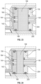
- the dual-chamber syringe 110 and dual-lumen IV set 800 transition to a pre-flushing state, as illustrated in FIG. 21 .
- the transition involves the syringe pump 1920 moving the secondary head 178 of the secondary plunger 148 axially toward the end wall 114 to deliver the remaining medication in the primary chamber 159 through the passage 138 and the primary nozzle 142 to the primary duct 830 and the primary lumen 816.
- the secondary valve 842 prevents saline flow from the secondary chamber 199 to the secondary lumen 818, pressure is increased against the valve 814 as the secondary plunger 148 is moved axially and is greater than the predetermined cracking pressure, such that the axially movement of the secondary plunger 148 forces the medication past the valve 814 and into the housing passage 826 to the catheter 1910 via the channel 824 and the exit port 822.
- the tapered tabs 174 are unseated from the first opposed plunger slots 194 and are moved towards the second opposed plunger slots 196.
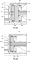
- FIG. 23 illustrates the pre-flushing state with the primary stopper 150 abutting the inner face 126 of the end wall 114 and medication residing in the channel 124 and the notch 136.
- the second primary O-ring 168 seals the notch 136 and prevents the medication from flowing into the secondary chamber 199.
- the pressure against the second primary O-ring 168 increases, such that the saline in the secondary chamber 199 is forced past the second primary O-ring 168 and through the notch 136 into the channel 124 and forces the medication to the primary nozzle 142 via the passage 138.
- the syringe pump 1920 continues to axially move the secondary plunger 148, such that the saline is forced from the secondary chamber 199 to flush the medication from the channel 124. In this manner, the saline forces the medication through the primary lumen 816 so that all of the medication is delivered to the patient and the dual-lumen IV set 800 is primed with saline.
- the dual-chamber syringe is pre-loaded with saline in the secondary chamber 199.
- the secondary chamber 199 is configured to receive the priming solution from the dual-lumen IV set 800, but is not utilized for reserved flushing.
- the secondary chamber 199 is configured to stop the secondary plunger 148 when receiving priming solution from the dual-lumen IV set 800 and is configured to indicate the dual-chamber syringe 110 is ready to infuse medication.
- the fluid delivery system 100 includes a valve lock to prevent fluid from being delivered to a patient during priming.
- the priming volume is selectable in 0.1 mL increments.
- the secondary plunger 148 includes a plunger handle base that rotates to allow the plunger rod to rotate and disengage while maintaining friction with a syringe pump paddle. In some aspects, the secondary plunger 148 is released automatically, instead of with a pin 209a, at a certain plunger depth so that infusion is not interrupted and does not require human interaction. In some aspects, the fluid delivery system 100 includes vents to vent residual air bubbles via air-permeable filters. In some aspects, the fluid delivery system 100 is configured to pre-set and limit the priming volume via a pin which limits plunger travel.
- a dual-chamber syringe comprising: an end wall; a primary plunger comprising a primary stopper, the primary stopper forming a primary chamber with the end wall; a secondary plunger in mechanical association with the primary plunger, the secondary plunger comprising a secondary stopper, the secondary stopper forming a secondary chamber with the primary stopper; a primary nozzle extending from the end wall, the primary nozzle in fluid communication with the primary chamber; and a secondary nozzle extending from the end wall, the secondary nozzle in fluid communication with the secondary chamber.
- Clause 8 The dual-chamber syringe of Clause 7, wherein the secondary chamber is in fluid communication with the primary nozzle via the channel when the dual-chamber syringe is transitioning from a pre-flushing state to a post-flushing state.
- Clause 10 The dual-chamber syringe of Clause 9, wherein the internal tube is received by a primary inner cavity of the primary plunger.
- a multi-lumen intravenous (IV) set comprising: an adapter comprising a primary duct and a secondary duct; a valve housing comprising a housing port and a housing passage; a primary lumen in fluid communication with the primary duct and the housing port; a secondary lumen in fluid communication with the secondary duct and the housing port; and a valve disposed in the valve housing, the valve comprising a cracking pressure, wherein the valve is configured to prevent fluid flow from the housing port to the housing passage when pressure against the valve is less than the cracking pressure, and wherein the valve is configured to allow fluid flow from the housing port to the housing passage when pressure against the valve is greater than the cracking pressure.
- Clause 12 The multi-lumen IV set of Clause 11, wherein the primary lumen is in fluid communication with the secondary lumen when pressure against the valve is less than the cracking pressure.
- Clause 13 The multi-lumen IV set of Clause 11 or 12, further comprising a primary septum disposed in the primary duct and a secondary septum disposed in the secondary duct.
- Clause 14 The multi-lumen IV set of Clause 13, wherein the primary septum is configured to seal a primary port disposed at the primary duct to prevent fluid flow from the primary port to the primary duct when unengaged with a medical device and is configured to allow fluid flow from the primary port to the primary duct when engaged with the medical device, and wherein the secondary septum is configured to seal a secondary port disposed at the secondary duct to prevent fluid flow from the secondary port to the secondary duct when unengaged with the medical device and is configured to allow fluid flow from the secondary port to the secondary duct when engaged with the medical device.
- Clause 15 The multi-lumen IV set of Clause 14, further comprising a secondary valve disposed in the secondary duct, the secondary valve configured to allow fluid flow from the secondary lumen to the secondary port and to prevent fluid flow from the secondary port to the secondary lumen.
- Clause 16 The multi-lumen IV set of Clause 15, wherein the secondary valve is a check valve.
- Clause 17 The multi-lumen IV set of Clause 14-16, wherein the primary port and the secondary port are asymmetrical.
- a fluid delivery system comprising: a dual-chamber syringe comprising, an end wall; a primary plunger comprising a primary stopper, the primary stopper forming a primary chamber with the end wall; a secondary plunger in mechanical association with the primary plunger, the secondary plunger comprising a secondary stopper, the secondary stopper forming a secondary chamber with the primary stopper; a primary nozzle extending from the end wall, the primary nozzle in fluid communication with the primary chamber; a secondary nozzle extending from the end wall, the secondary nozzle in fluid communication with the secondary chamber; and a multi-lumen intravenous set comprising, an adapter comprising a primary port and a secondary port, the primary port fluidly coupled to the primary nozzle and the secondary port fluidly coupled to the secondary nozzle; a valve housing comprising a housing port and a housing passage; a primary lumen in fluid communication with a primary duct disposed in the adapter and in fluid communication with the housing port; a secondary lumen in fluid communication with
- Clause 19 The fluid delivery system of Clause 18, wherein the primary plunger comprises a lock member configured to removably lock the primary plunger to the secondary plunger.
- Clause 20 The fluid delivery system of Clause 18 or 19, a secondary valve disposed in the secondary duct, the secondary valve configured to allow fluid flow from the secondary lumen to the secondary port and to prevent fluid flow from the secondary port to the secondary lumen.
- the phrase "at least one of' preceding a series of items, with the term “and” or “or” to separate any of the items, modifies the list as a whole, rather than each member of the list (i.e., each item).
- phrases “at least one of A, B, and C” or “at least one of A, B, or C” each refer to only A, only B, or only C; any combination of A, B, and C; and/or at least one of each of A, B, and C.
Landscapes
- Health & Medical Sciences (AREA)
- Vascular Medicine (AREA)
- Engineering & Computer Science (AREA)
- Anesthesiology (AREA)
- Biomedical Technology (AREA)
- Heart & Thoracic Surgery (AREA)
- Hematology (AREA)
- Life Sciences & Earth Sciences (AREA)
- Animal Behavior & Ethology (AREA)
- General Health & Medical Sciences (AREA)
- Public Health (AREA)
- Veterinary Medicine (AREA)
- Infusion, Injection, And Reservoir Apparatuses (AREA)
Abstract
Description
- The delivery of medical fluids to fluid-restricted patients often includes administering the medical fluid intravenously through an intravenous (IV) set from a fluid source at low flow rates. Traditional practice often involves breaking the line to deliver an IV push, which can be time consuming at such low flow rates. Other conventional practices may involve administering a priming solution to the fluid-restricted patient via a pump before delivering the medical fluid, which may delay the medical fluid from being administered to the fluid-restricted patient in a timely fashion.
- The disclosed subject matter relates to syringes. In certain embodiments, a dual-chamber syringe includes an end wall; a primary plunger comprising a primary stopper, the primary stopper forming a primary chamber with the end wall; a secondary plunger in mechanical association with the primary plunger, the secondary plunger comprising a secondary stopper, the secondary stopper forming a secondary chamber with the primary stopper; a primary nozzle extending from the end wall, the primary nozzle in fluid communication with the primary chamber; and a secondary nozzle extending from the end wall, the secondary nozzle in fluid communication with the secondary chamber.
- In certain embodiments, a multi-lumen intravenous (IV) set includes an adapter comprising a primary duct and a secondary duct; a valve housing comprising a housing port and a housing passage; a primary lumen in fluid communication with the primary duct and the housing port; a secondary lumen in fluid communication with the secondary duct and the housing port; and a valve disposed in the valve housing, the valve comprising a cracking pressure, wherein the valve is configured to prevent fluid flow from the housing port to the housing passage when pressure against the valve is less than the cracking pressure, and wherein the valve is configured to allow fluid flow from the housing port to the housing passage when pressure against the valve is greater than the cracking pressure.
- In certain embodiments, a fluid delivery system includes a dual-chamber syringe comprising, an end wall; a primary plunger comprising a primary stopper, the primary stopper forming a primary chamber with the end wall; a secondary plunger in mechanical association with the primary plunger, the secondary plunger comprising a secondary stopper, the secondary stopper forming a secondary chamber with the primary stopper; a primary nozzle extending from the end wall, the primary nozzle in fluid communication with the primary chamber; a secondary nozzle extending from the end wall, the secondary nozzle in fluid communication with the secondary chamber; and
a multi-lumen intravenous set comprising, an adapter comprising a primary port and a secondary port, the primary port fluidly coupled to the primary nozzle and the secondary port fluidly coupled to the secondary nozzle; a valve housing comprising a housing port and a housing passage; a primary lumen in fluid communication with a primary duct disposed in the adapter and in fluid communication with the housing port; a secondary lumen in fluid communication with a secondary duct disposed in the adapter and in fluid communication with the housing port; and a valve disposed in the valve housing, the valve comprising a cracking pressure, wherein the valve is configured to prevent fluid flow from the housing port to the housing passage when pressure against the valve is less than the cracking pressure, and wherein the valve is configured to allow fluid flow from the housing port to the housing passage when pressure against the valve is greater than the cracking pressure. - The accompanying drawings, which are included to provide further understanding of the subject technology and are incorporated in and constitute a part of this description, illustrate aspects of the subject technology and, together with the specification, serve to explain principles of the subject technology.
-
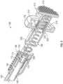
FIG. 1 illustrates a side view of a dual-chamber syringe, with portions sectioned and broken away to show details, in accordance with aspects of the present disclosure. -
FIG. 2 illustrates a perspective view of the dual-chamber syringe depicted inFIG. 1 in accordance with aspects of the present disclosure. -
FIG. 3 illustrates a cross-sectional perspective view, taken along line 3-3 of the dual-chamber syringe ofFIG. 1 , depicting an end wall of the syringe in accordance with aspects of the present disclosure. -
FIG. 4 illustrates a detailed cross-sectional view of a primary plunger of the dual-chamber syringe depicted inFIG. 1 in accordance with aspects of the present disclosure. -
FIG. 5 illustrates a detailed cross-sectional perspective view of the dual-chamber syringe ofFIG. 1 with an activator in an inactivated state in accordance with aspects of the present disclosure. -
FIG. 6 illustrates a detailed plan view of a snap lock of the primary plunger depicted inFIG. 5 in accordance with aspects of the present disclosure. -
FIG. 7 illustrates a detailed perspective view of the activator depicted inFIG. 5 , in an activated state, in accordance with aspects of the present disclosure. -
FIG. 8 illustrates a plan view of a dual-lumen intravenous (IV) set in accordance with aspects of the present disclosure. -
FIG. 9 illustrates a plan view of the dual-lumen IV set ofFIG. 8 , with portions sectioned away and in phantom to depict interior details of the dual-lumen IV set in accordance with aspects of the present disclosure. -
FIG. 10 illustrates a detailed perspective view of a dual-lumen tube adapter of the dual-lumen IV set ofFIG. 9 in accordance with aspects of the present disclosure. -
FIG. 11 illustrates a perspective view of a dual-chamber syringe adapter in accordance with aspects of the present disclosure. -
FIG. 12 illustrates a cross-sectional plan view taken along line 12-12 ofFIG. 11 in accordance with aspects of the present disclosure. -
FIG. 13 illustrates a perspective view of a flush syringe adapter in accordance with aspects of the present disclosure. -
FIG. 14 illustrates a cross-sectional plan view taken along line 14-14 ofFIG. 13 in accordance with aspects of the present disclosure. -
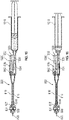
FIG. 15 illustrates a plan view of the dual-lumen IV set in use with a flush syringe in a pre-priming state, with portions sectioned and broken away to depict internal fluid passages, in accordance with aspects of the present disclosure. -
FIG. 16 illustrates a plan view of the dual-lumen IV set in use with the flush syringe ofFIG. 15 in a post-priming state, with portions sectioned and broken away to depict internal fluid passages, in accordance with aspects of the present disclosure. -
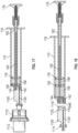
FIG. 17 illustrates a plan view of the dual-chamber syringe ofFIG. 1 , in a pre-filled state and in use with a vial, with portions sectioned and broken away to depict internal fluid passages, in accordance with aspects of the present disclosure. -
FIG. 18 illustrates a plan view of the dual-chamber syringe ofFIG. 17 , in a post-filled state with the vial and the dual-chamber syringe adapter removed from the dual-chamber syringe, with portions sectioned and broken away to depict internal fluid passages, in accordance with aspects of the present disclosure. -
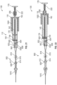
FIG. 19 illustrates a plan view of a fluid delivery system in a pre-priming of medication state, depicting the dual-chamber syringe ofFIG. 1 in use with the dual-lumen IV set ofFIG. 8 , with portions sectioned and broken away to depict internal fluid passages, in accordance with aspects of the present disclosure. -
FIG. 20 illustrates a plan view of the fluid delivery system ofFIG. 19 in a post-priming of medication state, depicting the dual-lumen IV set primed with medication, with portions sectioned and broken away to depict internal fluid passages, in accordance with aspects of the present disclosure. -
FIG. 21 illustrates a plan view of the fluid delivery system ofFIG. 19 in a pre-flushing state, with portions sectioned and broken away to depict internal fluid passages, in accordance with aspects of the present disclosure. -
FIG. 22 illustrates a plan view of the fluid delivery system ofFIG. 19 in a post-flushing state, with portions sectioned and broken away to depict internal fluid passages, in accordance with aspects of the present disclosure. -
FIGS. 23-26 illustrates detailed views of the dual-chamber syringe transitioning from the pre-flushing state depicted inFIG. 21 to the post-flushing state depicted inFIG. 22 . - In the following detailed description, specific details are set forth to provide an understanding of the subject technology. It will be apparent, however, to one ordinarily skilled in the art that the subject technology may be practiced without some of these specific details. In other instances, well-known structures and techniques have not been shown in detail so as not to obscure the subject technology.
- A phrase such as "an aspect" does not imply that such aspect is essential to the subject technology or that such aspect applies to all configurations of the subject technology. A disclosure relating to an aspect may apply to all configurations, or one or more configurations. An aspect may provide one or more examples of the disclosure. A phrase such as "an aspect" may refer to one or more aspects and vice versa. A phrase such as "an embodiment" does not imply that such embodiment is essential to the subject technology or that such embodiment applies to all configurations of the subject technology. A disclosure relating to an embodiment may apply to all embodiments, or one or more embodiments. An embodiment may provide one or more examples of the disclosure. A phrase such "an embodiment" may refer to one or more embodiments and vice versa. A phrase such as "a configuration" does not imply that such configuration is essential to the subject technology or that such configuration applies to all configurations of the subject technology. A disclosure relating to a configuration may apply to all configurations, or one or more configurations. A configuration may provide one or more examples of the disclosure. A phrase such as "a configuration" may refer to one or more configurations and vice versa.
-
FIGS. 1-25 illustrate a fluid delivery system including a syringe-pump-compatible, dual-chamber syringe couplable to a dual-lumen intravenous (IV) set. The fluid delivery system is configured to remove priming solution from the dual-lumen IV set for reserve in the dual-chamber syringe, deliver medication at a pre-determined flow rate, and administer remaining medication residing in the dual-lumen IV set by restoring the reserved priming solution in the dual-chamber syringe to the dual-lumen IV set. -
FIGS. 1-6 illustrate an embodiment of a dual-chamber syringe 110 of a fluid delivery system 100 (shown inFIG. 19 ). In some embodiments, the dual-chamber syringe 110 includes acylindrical syringe barrel 112, anend wall 114, and asyringe collar 116. Theend wall 114 is disposed at afirst end 118 of thesyringe barrel 112 while thesyringe collar 116 is disposed at asecond end 120 of thesyringe barrel 112, which is opposite thefirst end 118. Thesyringe collar 116 extends radially outwardly from thesyringe barrel 112 proximate thesecond end 120. Thesyringe barrel 112 includes a cylindrical inner chamber 122 extending between theend wall 114 and thesyringe collar 116. - With particular reference to
FIG. 3 , agrooved channel 124 is recessed in aninner face 126 of theend wall 114. Theinner face 126 faces the inner chamber 122 and is disposed therein. Thechannel 124 includes anotch end 128, apassage end 130, and adivot 132 disposed between thenotch end 128 and thepassage end 130. In some aspects, thechannel 124 includes opposingbeveled walls 134, which extend between thenotch end 128 and thedivot 132 and between thedivot 132 and thepassage end 130. Thenotch end 128 is in fluid communication with anotch 136, which is disposed in thesyringe barrel 112 at an intersection of thesyringe barrel 112 and theend wall 114 proximate thefirst end 118. Thenotch 136 extends axially inwardly from theend wall 114 within the inner chamber 122. Thepassage end 130 is in fluid communication with apassage 138 disposed through theend wall 114. In some aspects, thechannel 124 extends along a portion of a diameter of theinner face 126. Thenotch 136, thechannel 124, and thepassage 138 collectively form a flushing fluid flow path of which the features and functionality will be described in more detail below. - The dual-
chamber syringe 110 also includes aninternal tube 140. Theinternal tube 140 is disposed through thedivot 132 and theinner face 126 of theend wall 114 and extends axially inwardly within the inner chamber 122. Theinternal tube 140 terminates within the inner chamber 122 and is offset axially inwardly with respect to thesyringe collar 116. In some aspects, theinternal tube 140 extends substantially centrally through thedivot 132 and theinner face 126 of theend wall 114 and is disposed centrally within the inner chamber 122. - The dual-
chamber syringe 110 also includes aprimary nozzle 142 and asecondary nozzle 144. Both theprimary nozzle 142 and thesecondary nozzle 144 extend axially outwardly from theend wall 114 and are disposed externally with respect to the inner chamber 122. In some aspects, thesecondary nozzle 144 is disposed centrally on theend wall 114. Thesecondary nozzle 144 is coaxially aligned with theinternal tube 140 and is in fluid communication with theinternal tube 140. Theprimary nozzle 142 is radially offset on theend wall 114 from thesecondary nozzle 144. Theprimary nozzle 142 is in fluid communication with a primary chamber 145 of the inner chamber 122 via thepassage 138. Anozzle guide 143 also extends axially outwardly from theend wall 114 and surrounds both theprimary nozzle 142 and thesecondary nozzle 144 to facilitate connecting the dual-chamber syringe 110 to other medical components. In some aspects, theprimary nozzle 142 and thesecondary nozzle 144 are asymmetrical to prevent reversed or backwards coupling of the dual-chamber syringe 110 to the dual-lumen IV set (800). In some aspects, theprimary nozzle 142 and thesecondary nozzle 144 are male Luer connectors. In other aspects, theprimary nozzle 142 is a male Luer connector and thesecondary nozzle 144 is a needle-free connector. In yet other aspects, theprimary nozzle 142 is a needle-free connector and thesecondary nozzle 144 is a male Luer connector. - Moreover, the dual-
chamber syringe 110 includes aprimary plunger 146 and asecondary plunger 148. Theprimary plunger 146 is in mechanical association with thesecondary plunger 148, such that both are received by the inner chamber 122 and are configured for slidable movement within the inner chamber 122. Theprimary plunger 146 includes aprimary stopper 150, aprimary head 152, and arod 154 extending between theprimary stopper 150 and theprimary head 152. Theprimary stopper 150 is disposed at afirst rod end 156 of therod 154 and theprimary head 152 is disposed at asecond rod end 158 of therod 154. Theprimary plunger 146 is arranged within the inner chamber 122, such that aprimary chamber 159 is disposed between theprimary stopper 150 and theinner face 126 of theend wall 114. Theprimary plunger 146 includes aprimary receiving aperture 160 disposed centrally through theprimary stopper 150. Therod 154 extends from theprimary stopper 150 and includes a primaryinner cavity 162, such that the primaryinner cavity 162 is aligned with theprimary receiving aperture 160. Theprimary receiving aperture 160 and the primaryinner cavity 162 are configured to slidably receive theinternal tube 140 of the dual-chamber syringe 110. In some aspects, a first primary O-ring 164 is disposed in theprimary receiving aperture 160, such that theinternal tube 140 is slidably and sealingly received by the first primary O-ring 164 and is slidably received by the primaryinner cavity 162. Achamber passage 166 is disposed through therod 154 proximate an intersection of therod 154 and theprimary stopper 150. In some aspects, a second primary O-ring 168 is disposed around theprimary stopper 150 for sealing engagement withsyringe barrel 112. - The
primary plunger 146 includes alock member 170 disposed on therod 154 between the primaryinner cavity 162 and theprimary head 152. With particular reference toFIG. 6 , thelock member 170 includes opposedrod flanges 172. Each rod flange of the opposedrod flanges 172 includes a taperedtab 174, which protrudes radially outwardly and tapers axially towards theprimary head 152. Theopposed rod flanges 172 are depressible radially inwardly toward each other. Thelock member 170 is mechanically associated with components of thesecondary plunger 148 to releasably lock with theprimary plunger 146, which will be described in more detail below. - The
secondary plunger 148 includes asecondary stopper 176, asecondary head 178, and abody 180 extending between thesecondary stopper 176 and thesecondary head 178. Thesecondary stopper 176 is disposed at afirst body end 182 of thebody 180 and thesecondary head 178 is disposed at asecond body end 184 of thebody 180. Thebody 180 includes amain section 186 and aneck section 188. In some aspects, themain section 186 of thebody 180 includes wings including a plus-sign (e.g., +) cross-section. Themain section 186 transitions to theneck section 188 at a tapered section 190. In some aspects, theneck section 188 includes aneck 192 disposed between the tapered section 190 and thesecondary head 178. Theneck 192 includes, sequentially in a direction from the tapered section 190 to thesecondary head 178, first opposedplunger slots 194, second opposedplunger slots 196, opposedactivator lock slots 198, and opposedactivator rest slots 200. Moreover, thesecondary plunger 148 includes asecondary receiving aperture 201 disposed centrally through thesecondary stopper 176 and ahead aperture 202 disposed centrally through thesecondary head 178. Thesecondary plunger 148 includes a secondaryinner cavity 203 extending from thesecondary stopper 176 at thesecondary receiving aperture 201 to thesecondary head 178 at thehead aperture 202. Thesecondary receiving aperture 201 and the secondaryinner cavity 203 are configured to slidably receive therod 154 of theprimary plunger 146. In such an arrangement within the inner chamber 122, asecondary chamber 199 of the inner chamber 122 is disposed between thesecondary stopper 176 and theprimary stopper 150. In some aspects, a first secondary O-ring 204 is disposed in thesecondary receiving aperture 201, such that therod 154 is slidably and sealingly received by the first secondary O-ring 204 and is slidably received by the secondaryinner cavity 203. In some aspects, a second secondary O-ring 205 is disposed around thesecondary stopper 176 for sealing engagement with thesyringe barrel 112. -
Opposed lock flanges 206 protrude outwardly from theneck 192 and extend axially alongside theneck 192. Anub 208 protrudes radially inwardly from each lock flange of theopposed lock flanges 206. Thenubs 208 are aligned with the secondopposed plunger slots 196. Theopposed lock flanges 206 are configured to urge radially inwardly toward each other, such thatnubs 208 are received by the secondopposed plunger slots 196. Theopposed lock flanges 206 are deformable and configured to be urged radially outwardly away from each other when engaged with apin 209a. For example, thepin 209a includes apull tab 209b formed to aclasp 209c, such that theclasp 209c is removably fastened around theneck 192 and arranged between theopposed lock flanges 206 and theneck 192 to urge theopposed lock flanges 206 radially outwardly. With the opposedlock flanges 206 urged radially outwardly away from each other, thenubs 208 are held radially outwardly away from the secondopposed plunger slots 196. - The
secondary plunger 148 includes aseat 210 centrally recessed into thesecondary head 178 and aligned coaxially with the secondaryinner cavity 203 and thehead aperture 202. Thesecondary plunger 148 also includes anactivator 212. Theactivator 212 includes anactivator body 214 and anactivator head 216, which sits on theactivator body 214. Theactivator body 214 is substantially cylindrical and includes opposedactivator flanges 218 formed in theactivator body 214. Each activator flange of the opposedactivator flanges 218 includes a taperedtab 220, which protrudes radially outwardly and tapers axially inwardly. Theopposed activator flanges 218 are depressible radially inwardly toward each other. Theactivator body 214 is received by thehead aperture 202, such that, in the inactivated state of theactivator 212, the taperedtabs 220 of the opposedactivator flanges 218 are received by the opposedactivator rest slots 200 and, in an activated state of theactivator 212, the taperedtabs 220 are received by, and seated at, the opposedactivator lock slots 198 while theactivator head 216 is received by theseat 210. Moreover, when the dual-chamberedsyringe 110 is assembled, aresilient member 222 is disposed within theneck 192 between theactivator head 216 and theprimary head 152 of theprimary plunger 146. Theresilient member 222 is in an uncompressed state when theactivator 212 is in the inactivated state and is in a compressed state when theactivator 212 is in the activated state. - With reference to
FIGS. 8-10 , thefluid delivery system 100 also includes a dual-lumen intravenous (IV) set 800, which is couplable to the dual-chamber syringe 110. Although the dual-lumen IV set 800 is illustrated with broken lines depicting a shortened length, it should be understood that the length of the dual-lumen IV set 800 can be any length including, but not limited to, 1 meter, 2 meters, 3 meters, etc. The dual-lumen IV set 800 includes aconnector 810, avalve housing 812, avalve 814, aprimary lumen 816, asecondary lumen 818, and anadapter 820. Theconnector 810 includes anexit port 822 and achannel 824 fluidly connected to theexit port 822. Theconnector 810 is configured to couple with a medical device, such as, for example, a catheter (now shown). Although thefluid delivery system 100 is illustrated with one dual-lumen IV set 800, it is within the scope of the present application that thefluid delivery system 100 includes multiple dual-lumen IV sets to deliver multiple drugs via multiple dual-chamber syringes in one IV set. Thechannel 824 is also fluidly connected to ahousing passage 826 disposed in thevalve housing 812. In some aspects, thechannel 824 tapers from thehousing passage 826 toward theexit port 822. Ahousing port 828 is also disposed in thevalve housing 812 and is in fluid communication with thehousing passage 826. An end of each of theprimary lumen 816 and thesecondary lumen 818 are received by, and in fluid communication with, thehousing port 828. The other end of theprimary lumen 816 is in fluid communication with aprimary duct 830 disposed in theadapter 820 while the other end of thesecondary lumen 818 is in fluid communication with asecondary duct 832 also disposed in theadapter 820, which is offset from theprimary duct 830. - The
valve 814 is disposed in thevalve housing 812 and is configured to seal thehousing port 828 from thehousing passage 826 until a predetermined cracking pressure is achieved against thevalve 814 from thehousing port 828 at which point fluid is allowed to flow from thehousing port 828 past thevalve 814 and to thehousing passage 826. In some aspects, thevalve 814 is a one-way valve, such as, but not limited to, a check valve or an anti-siphon valve. The predetermined cracking pressure can be selected to crack at any predetermine pressure, such as, for example, 1 psi (pounds per square inch) or a half psi. - The
adapter 820 also includes aprimary septum 834 and asecondary septum 836. Theprimary septum 834 is disposed in theprimary duct 830. Theprimary septum 834 is configured to seal aprimary port 838 of theadapter 820, which is disposed at an end of theprimary duct 830, to prevent fluid flow from theprimary port 838 to theprimary duct 830 when unengaged with a medical device. When theadapter 820 is coupled to the dual-chamber syringe 110, however, theprimary nozzle 142 engages theprimary septum 834 allowing fluid from theprimary nozzle 142 to flow through theprimary port 838 to theprimary lumen 816 via theprimary duct 830. Thesecondary septum 836 is disposed in thesecondary duct 832 and is configured to seal asecondary port 840 of theadapter 820, which is disposed at an end of thesecondary duct 832, to prevent fluid flow from thesecondary duct 832 to thesecondary port 840 when unengaged with a medical device. When theadapter 820 is coupled to the dual-chamber syringe 110, however, thesecondary nozzle 144 engages thesecondary septum 836 allowing fluid from thesecondary duct 832 to flow through thesecondary port 840 to thesecondary nozzle 144. Moreover, asecondary valve 842 is disposed in thesecondary duct 832 to allow fluid flow from thesecondary lumen 818 to thesecondary nozzle 144 via thesecondary duct 832, but prevents fluid flow in the opposite direction from thesecondary nozzle 144 tosecondary lumen 818. In some aspects, thesecondary valve 842 is a one-way valve, such as, but not limited to a duckbill valve or a check valve. Because in some aspects theprimary nozzle 142 and thesecondary nozzle 144 are asymmetrical, theprimary nozzle 142 is configured to be received only by theprimary port 838 and cannot be received by thesecondary port 840 while thesecondary nozzle 144 is configured to be received only by thesecondary port 840 and cannot be received by theprimary port 838 to prevent reversed or backwards coupling of the dual-chamber syringe 110 to the dual-lumen IV set 800. - The
adapter 820 also includes aridge 844 disposed around the exterior and axially offset inwardly from theprimary port 838 and thesecondary port 840. Theridge 844 is configured to removably snap fit or interlock with aseat 846 disposed on the interior of thenozzle guide 143 when the dual-chamber syringe 110 and the dual-lumen IV set 800 are coupled together. In some aspects, a first plurality of serrations 848 is disposed on the exterior of theadapter 820 to facilitate gripping when being hand-held. - With reference to
FIGS. 11-12 , thefluid delivery system 100 also includes a dual-chamber syringe adapter 1100. The dual-chamber syringe adapter 1100 is couplable to the dual-chamber syringe 110 and a vial adapter 1110 (shown inFIG. 17 ), which is in turn coupled to a vial 1112 (also shown inFIG. 17 ). The dual-chamber syringe adapter 1100 is configured to transfer fluid in thevial 1112 to the dual-chamber syringe 110. The dual-chamber syringe adapter 1100 includes amale connector 1114, aprimary nozzle receiver 1116, asecondary nozzle receiver 1118, and aconduit 1120. In some aspects, a second plurality ofserrations 1121 is disposed on the exterior of the dual-chamber syringe adapter 1100 to facilitate gripping when being hand-held. Theconduit 1120 is disposed through the dual-chamber syringe adapter 1100 and fluidly couples themale connector 1114 to theprimary nozzle receiver 1116. Anozzle seat 1122 is disposed in thesecondary nozzle receiver 1118 for sealing engagement with thesecondary nozzle 144 and preventing any fluid flow through thesecondary nozzle 144. The dual-chamber syringe adapter 1100 also includes acap 1124 hingedly coupled to themale connector 1114 for removably capping or closing themale connector 1114. In some aspects, themale connector 1114 is a male Luer connector. Themale connector 1114 is configured to couple with a female connector of thevial adapter 1110. Theprimary nozzle receiver 1116 is configured to matingly receive theprimary nozzle 142 of the dual-chamber syringe 110 and thesecondary nozzle receiver 1118 is configured to matingly receive thesecondary nozzle 144 of the dual-chamber syringe 110 while anadapter ridge 1126 disposed on the exterior of the dual-chamber syringe adapter 1100 removably snap fits or interlocks with theseat 846. When the dual-chamber syringe adapter 1100 is coupled to the dual-chamber syringe 110 fluid in thevial 1112 is capable of being drawn into theprimary chamber 159 through theprimary nozzle 142 via thevial adapter 1110, themale connector 1114, and theconduit 1120. - With reference to
FIGS. 13 and14 , thefluid delivery system 100 also includes aflush syringe adapter 1300. Theflush syringe adapter 1300 is couplable to a flush syringe 1310 (shown inFIG. 15 ) and theadapter 820 of the dual-lumen IV set 800. Theflush syringe adapter 1300 is configured to transfer fluid from theflush syringe 1310 to prime the dual-lumen IV set 800 with saline. Theflush syringe adapter 1300 includes aprimary adapter nozzle 1312, asecondary adapter nozzle 1314, asyringe guide 1316, afemale connector 1318, aprimary passage 1320, and asecondary passage 1322. In some aspects, a third plurality ofserrations 1324 is disposed on the exterior of theflush syringe adapter 1300 to facilitate gripping when being hand-held. Thesyringe guide 1316 surrounds theprimary adapter nozzle 1312 and thesecondary adapter nozzle 1314 to facilitate coupling theflush syringe adapter 1300 to the dual-lumen IV set 800 so that theprimary adapter nozzle 1312 is received by theprimary port 838 of theadapter 820 and thesecondary adapter nozzle 1314 is received by thesecondary port 840. In some aspects, theprimary adapter nozzle 1312 and thesecondary adapter nozzle 1314 are asymmetrical, such that theprimary adapter nozzle 1312 is configured to be received only by theprimary port 838 and cannot be received by thesecondary port 840 while thesecondary adapter nozzle 1314 is configured to be received only by thesecondary port 840 and cannot be received by theprimary port 838 to prevent reversed or backwards coupling of theflush syringe adapter 1300 to the dual-lumen IV set 800. In some aspects, theprimary adapter nozzle 1312 and thesecondary adapter nozzle 1314 are male Luer connectors. In other aspects, theprimary adapter nozzle 1312 is a male Luer connector and thesecondary adapter nozzle 1314 is a needle-free connector. In yet other aspects, theprimary adapter nozzle 1312 is a needle-free connector and thesecondary adapter nozzle 1314 is a male Luer connector. - The
primary passage 1320 is disposed between, and fluidly couples, theprimary adapter nozzle 1312 and anadapter port 1328 disposed at thefemale connector 1318. In some aspects, thefemale connector 1318 is a female Luer connector. Thefemale connector 1318 is configured to couple with a male connector of theflush syringe 1310. In some aspects, the male connector of theflush syringe 1310 is a male Luer connector. Thesecondary passage 1322 is disposed between, and fluidly couples, thesecondary adapter nozzle 1314 and avent 1330. Ahydrophobic element 1332 is disposed in thesecondary passage 1322 and is configured to allow air from thesecondary adapter nozzle 1314 to escape through thevent 1330, but when thehydrophobic element 1332 contacts liquid fluid (e.g., saline from the flush syringe 1310) it prevents the liquid fluid from flowing out of thevent 1330. -
FIG. 15 illustrates the dual-lumen IV set 800 in use with theflush syringe 1310 in a pre-priming state andFIG. 16 illustrates the dual-lumen IV set 800 in use with theflush syringe 1310 in a post-priming state. In order to prime the dual-lumen IV set 800, which may occur at a patient bedside, theflush syringe adapter 1300 is coupled to the dual-lumen IV set 800, such that theprimary adapter nozzle 1312 and thesecondary adapter nozzle 1314 are received by theprimary port 838 and thesecondary port 840, respectively, and theadapter seat 1326 removably snap fits with theridge 844 of theadapter 820. With theflush syringe adapter 1300 coupled to the dual-lumen IV set 800, the dual-chamber syringe adapter 1100, which is pre-filled with saline, is coupled to theflush syringe adapter 1300 via thefemale connector 1318. Theflush syringe 1310 delivers the saline through theadapter port 1328 and theprimary passage 1320 into theprimary port 838 and theprimary duct 830. The saline flows from theprimary duct 830 through theprimary lumen 816 until it reaches thehousing port 828 and thevalve 814. The pressure against thevalve 814 is less than the predetermined cracking pressure so the saline travels through thesecondary lumen 818 and thesecondary valve 842. During this flow process, air in the dual-lumen IV set 800 has been pushed through thehydrophobic element 1332 and out thevent 1330, but once the saline contacts thehydrophobic element 1332, it prevents the saline from flowing any further. As the saline is prevented from flowing past thehydrophobic element 1332, the rest of the dual-lumen IV set 800 is primed with the saline. After the dual-lumen IV set 800 is fully primed, it can then be coupled to a medical device, such as a catheter. With the dual-lumen IV set 800 coupled to the catheter, the rest of the saline in theflush syringe 1310 is flushed through creating a pressure against thevalve 814, because thehydrophobic element 1332 is preventing saline flow, that is higher than the predetermined cracking pressure, such that thevalve 814 allows the saline to flow past to thehousing passage 826 and out theexit port 822 to the catheter. Theflush syringe adapter 1300, along with theflush syringe 1310, is then uncoupled from the dual-lumen IV set 800. -
FIG. 17 illustrates the dual-chamber syringe 110 in a pre-filled state and in use with thevial 1112 andFIG. 18 illustrates the dual-chamber syringe 110, in a post-filled state with thevial 1112 and the dual-chamber syringe adapter 1100 uncoupled from the dual-chamber syringe 110. Thepin 209a is inserted around theneck 192 urging theopposed lock flanges 206 radially outwardly, such that thenubs 208 are held radially outwardly away from the secondopposed plunger slots 196. With thenubs 208 arranged in this manner, the taperedtabs 174 of thelock member 170 are removably received at the secondopposed plunger slots 196 locking theprimary plunger 146 to thesecondary plunger 148. With theactivator 212 in the inactivated state, the taperedtabs 220 of the opposedactivator flanges 218 are received by and seated at the opposedactivator rest slots 200, such that theresilient member 222 is in its uncompressed state between theprimary head 152 of theprimary plunger 146 and theactivator head 216. This arrangement locks theprimary plunger 146 to thesecondary plunger 148 so that theprimary stopper 150 is offset from thesecondary stopper 176 at a predetermined distance, which can be preselected according to specific desires of a pre-filled volume of thesecondary chamber 199. The dual-chamber syringe 110 is pre-filled with saline in thesecondary chamber 199, as illustrated inFIG. 17 . - In use, such as at a pharmacy environment, the
activator 212 of the dual-chamber syringe 110 is activated by compressing theactivator head 216 axially inward, such that the taperedtabs 220 of the opposedactivator flanges 218 are depressed radially towards each other, unseated from the opposedactivator rest slots 200, and received by the opposedactivator lock slots 198 in locking fashion while theactivator head 216 is received by theseat 210. In this arrangement, theresilient member 222 is in its compressed state between theprimary head 152 of theprimary plunger 146 and theactivator head 216 positioned at theseat 210. Allowing theresilient member 222 to be in the uncompressed state before use can extend the shelf life of the dual-chamber syringe 110. After activating theactivator 212, the dual-chamber syringe 110 is coupled to the dual-chamber syringe adapter 1100, such that thenozzle guide 143 facilitates theprimary nozzle 142 being matingly inserted into theprimary nozzle receiver 1116 and thesecondary nozzle 144 being matingly inserted into thesecondary nozzle receiver 1118 while theadapter ridge 1126 removably snap fits or interlocks with theseat 846. With thesecondary nozzle 144 received by thesecondary nozzle receiver 1118 and seated against thenozzle seat 1122, the saline is prevented from accidentally flowing out of thesecondary chamber 199 during fluid transfer from thevial 1112 to the dual-chamber syringe 110. - With the dual-
chamber syringe adapter 1100 coupled to the dual-chamber syringe 110, themale connector 1114 is coupled to thevial adapter 1110, which is coupled to thevial 1112. As theprimary plunger 146 is locked to thesecondary plunger 148, pulling thesecondary head 178 axially away from thesyringe collar 116 will draw the fluid in the vial 1112 (e.g., medicine) through the dual-chamber syringe adapter 1100 and theprimary nozzle 142 and into theprimary chamber 159 via thepassage 138, and without disturbing the saline in thesecondary chamber 199, theinternal tube 140, and the primaryinner cavity 162. Once the desired amount of medicine is drawn into theprimary chamber 159 the dual-chamber syringe adapter 1100 can be uncoupled from the dual-chamber syringe 110, as depicted inFIG. 18 . -
FIG. 19 illustrates the dual-chamber syringe 110 of thefluid delivery system 100 in a pre-priming of medication state and in use with the dual-lumen IV set 800. The dual-lumen IV set 800 is primed with saline and is fluidly coupled to acatheter 1910. The dual-lumen IV set 800 is also fluidly coupled to the dual-chamber syringe 110, which is in mechanical engagement with asyringe pump 1920. While thesyringe pump 1920 securely supports thesyringe barrel 112, thesyringe pump 1920 is also in mechanical engagement with thesecondary head 178 to selectively control axially movement of thesecondary plunger 148. - From the pre-priming of medication state, the dual-
chamber syringe 110 and dual-lumen IV set 800 transition to a post-priming of medication state, as illustrated inFIG. 20 . The transition involves removing thepin 209a from theneck 192, such that theopposed lock flanges 206 are urged radially towards each other and thenubs 208 engage the taperedtabs 174 of thelock member 170 releasing the taperedtabs 174 from the secondopposed plunger slots 196. With thesecondary head 178 held in place by thesyringe pump 1920, the release or unseating of the taperedtabs 174 from the secondopposed plunger slots 196 allows theresilient member 222, in the compressed state, to urge against theprimary head 152, which in turn urges theprimary plunger 146 axially toward theend wall 114. As theprimary plunger 146 is urged axially toward theend wall 114, the medication in theprimary chamber 159 is forced through thepassage 138 and out theprimary nozzle 142 into theprimary duct 830 to theprimary lumen 816. At the same time, and because the pressure against thevalve 814 is less than the predetermined cracking pressure, the medication is displacing the saline that was primed in the dual-lumen IV set 800 to travel out thesecondary port 840 and through thesecondary nozzle 144 to fill thesecondary chamber 199 via theinternal tube 140, the primaryinner cavity 162, and thechamber passage 166. Theprimary plunger 146 continues to prime the dual-lumen IV set 800 with the medication until the taperedtabs 174 are received by, and seated against, the firstopposed plunger slots 194, which prevents theresilient member 222 from urging theprimary plunger 146 any further. - From the post-priming of medication state, the dual-
chamber syringe 110 and dual-lumen IV set 800 transition to a pre-flushing state, as illustrated inFIG. 21 . The transition involves thesyringe pump 1920 moving thesecondary head 178 of thesecondary plunger 148 axially toward theend wall 114 to deliver the remaining medication in theprimary chamber 159 through thepassage 138 and theprimary nozzle 142 to theprimary duct 830 and theprimary lumen 816. Because thesecondary valve 842 prevents saline flow from thesecondary chamber 199 to thesecondary lumen 818, pressure is increased against thevalve 814 as thesecondary plunger 148 is moved axially and is greater than the predetermined cracking pressure, such that the axially movement of thesecondary plunger 148 forces the medication past thevalve 814 and into thehousing passage 826 to thecatheter 1910 via thechannel 824 and theexit port 822. As thesecondary plunger 148 is being moved axially toward theend wall 114, the taperedtabs 174 are unseated from the firstopposed plunger slots 194 and are moved towards the secondopposed plunger slots 196. - Once the
primary stopper 150 abuts theinner face 126 of theend wall 114, the dual-chamber syringe 110 and dual-lumen IV set 800 transitions from the pre-flushing state to a post-flushing state, as illustrated inFIG. 22 . The transition is illustrated inFIGS. 23-26 .FIG. 23 illustrates the pre-flushing state with theprimary stopper 150 abutting theinner face 126 of theend wall 114 and medication residing in thechannel 124 and thenotch 136. The second primary O-ring 168 seals thenotch 136 and prevents the medication from flowing into thesecondary chamber 199. As thesecondary plunger 148 is continued to be moved axially toward theend wall 114 during the transition, the pressure against the second primary O-ring 168 increases, such that the saline in thesecondary chamber 199 is forced past the second primary O-ring 168 and through thenotch 136 into thechannel 124 and forces the medication to theprimary nozzle 142 via thepassage 138. Thesyringe pump 1920 continues to axially move thesecondary plunger 148, such that the saline is forced from thesecondary chamber 199 to flush the medication from thechannel 124. In this manner, the saline forces the medication through theprimary lumen 816 so that all of the medication is delivered to the patient and the dual-lumen IV set 800 is primed with saline. - In some aspects, the dual-chamber syringe is pre-loaded with saline in the
secondary chamber 199. In some aspects, thesecondary chamber 199 is configured to receive the priming solution from the dual-lumen IV set 800, but is not utilized for reserved flushing. In some aspects, thesecondary chamber 199 is configured to stop thesecondary plunger 148 when receiving priming solution from the dual-lumen IV set 800 and is configured to indicate the dual-chamber syringe 110 is ready to infuse medication. In some aspects, thefluid delivery system 100 includes a valve lock to prevent fluid from being delivered to a patient during priming. In some aspects, the priming volume is selectable in 0.1 mL increments. In some aspects, thesecondary plunger 148 includes a plunger handle base that rotates to allow the plunger rod to rotate and disengage while maintaining friction with a syringe pump paddle. In some aspects, thesecondary plunger 148 is released automatically, instead of with apin 209a, at a certain plunger depth so that infusion is not interrupted and does not require human interaction. In some aspects, thefluid delivery system 100 includes vents to vent residual air bubbles via air-permeable filters. In some aspects, thefluid delivery system 100 is configured to pre-set and limit the priming volume via a pin which limits plunger travel. - Various examples of aspects of the disclosure are described as numbered clauses (1, 2, 3, etc.) for convenience. These are provided as examples, and do not limit the subject technology. Identifications of the figures and reference numbers are provided below merely as examples and for illustrative purposes, and the clauses are not limited by those identifications.
- Clause 1. A dual-chamber syringe, comprising: an end wall; a primary plunger comprising a primary stopper, the primary stopper forming a primary chamber with the end wall; a secondary plunger in mechanical association with the primary plunger, the secondary plunger comprising a secondary stopper, the secondary stopper forming a secondary chamber with the primary stopper; a primary nozzle extending from the end wall, the primary nozzle in fluid communication with the primary chamber; and a secondary nozzle extending from the end wall, the secondary nozzle in fluid communication with the secondary chamber.
- Clause 2. The dual-chamber syringe of Clause 1, wherein the secondary nozzle extends centrally from the end wall.
-
Clause 3. The dual-chamber syringe of Clause 2, wherein the primary nozzle is radially offset from the secondary nozzle. - Clause 4. The dual-chamber syringe of any preceding Clause, wherein the primary nozzle and the secondary nozzle are asymmetric.
- Clause 5. The dual-chamber syringe of any preceding Clause, further comprising a nozzle guide extending from the end wall and surrounding the primary nozzle and the secondary nozzle. Clause 6. The dual-chamber syringe of any preceding Clause, wherein the primary plunger is lockable to the secondary plunger.
- Clause 7. The dual-chamber syringe of any preceding Clause, wherein the end wall comprises a channel.
-
Clause 8. The dual-chamber syringe of Clause 7, wherein the secondary chamber is in fluid communication with the primary nozzle via the channel when the dual-chamber syringe is transitioning from a pre-flushing state to a post-flushing state. - Clause 9. The dual-chamber syringe of any preceding Clause, wherein the secondary nozzle is in fluid communication with the secondary chamber via an internal tube extending from the end wall.
- Clause 10. The dual-chamber syringe of Clause 9, wherein the internal tube is received by a primary inner cavity of the primary plunger.
- Clause 11. A multi-lumen intravenous (IV) set, comprising: an adapter comprising a primary duct and a secondary duct; a valve housing comprising a housing port and a housing passage; a primary lumen in fluid communication with the primary duct and the housing port; a secondary lumen in fluid communication with the secondary duct and the housing port; and a valve disposed in the valve housing, the valve comprising a cracking pressure, wherein the valve is configured to prevent fluid flow from the housing port to the housing passage when pressure against the valve is less than the cracking pressure, and wherein the valve is configured to allow fluid flow from the housing port to the housing passage when pressure against the valve is greater than the cracking pressure.
-
Clause 12. The multi-lumen IV set of Clause 11, wherein the primary lumen is in fluid communication with the secondary lumen when pressure against the valve is less than the cracking pressure. - Clause 13. The multi-lumen IV set of
Clause 11 or 12, further comprising a primary septum disposed in the primary duct and a secondary septum disposed in the secondary duct. -
Clause 14. The multi-lumen IV set of Clause 13, wherein the primary septum is configured to seal a primary port disposed at the primary duct to prevent fluid flow from the primary port to the primary duct when unengaged with a medical device and is configured to allow fluid flow from the primary port to the primary duct when engaged with the medical device, and wherein the secondary septum is configured to seal a secondary port disposed at the secondary duct to prevent fluid flow from the secondary port to the secondary duct when unengaged with the medical device and is configured to allow fluid flow from the secondary port to the secondary duct when engaged with the medical device. - Clause 15. The multi-lumen IV set of
Clause 14, further comprising a secondary valve disposed in the secondary duct, the secondary valve configured to allow fluid flow from the secondary lumen to the secondary port and to prevent fluid flow from the secondary port to the secondary lumen. - Clause 16. The multi-lumen IV set of Clause 15, wherein the secondary valve is a check valve.
- Clause 17. The multi-lumen IV set of Clause 14-16, wherein the primary port and the secondary port are asymmetrical.
- Clause 18. A fluid delivery system, comprising: a dual-chamber syringe comprising, an end wall; a primary plunger comprising a primary stopper, the primary stopper forming a primary chamber with the end wall; a secondary plunger in mechanical association with the primary plunger, the secondary plunger comprising a secondary stopper, the secondary stopper forming a secondary chamber with the primary stopper; a primary nozzle extending from the end wall, the primary nozzle in fluid communication with the primary chamber; a secondary nozzle extending from the end wall, the secondary nozzle in fluid communication with the secondary chamber; and a multi-lumen intravenous set comprising, an adapter comprising a primary port and a secondary port, the primary port fluidly coupled to the primary nozzle and the secondary port fluidly coupled to the secondary nozzle; a valve housing comprising a housing port and a housing passage; a primary lumen in fluid communication with a primary duct disposed in the adapter and in fluid communication with the housing port; a secondary lumen in fluid communication with a secondary duct disposed in the adapter and in fluid communication with the housing port; and a valve disposed in the valve housing, the valve comprising a cracking pressure, wherein the valve is configured to prevent fluid flow from the housing port to the housing passage when pressure against the valve is less than the cracking pressure, and wherein the valve is configured to allow fluid flow from the housing port to the housing passage when pressure against the valve is greater than the cracking pressure.
- Clause 19. The fluid delivery system of Clause 18, wherein the primary plunger comprises a lock member configured to removably lock the primary plunger to the secondary plunger. Clause 20. The fluid delivery system of Clause 18 or 19, a secondary valve disposed in the secondary duct, the secondary valve configured to allow fluid flow from the secondary lumen to the secondary port and to prevent fluid flow from the secondary port to the secondary lumen. The foregoing description is provided to enable a person skilled in the art to practice the various configurations described herein. While the subject technology has been particularly described with reference to the various figures and configurations, it should be understood that these are for illustration purposes only and should not be taken as limiting the scope of the subject technology.
- There may be many other ways to implement the subject technology. Various functions and elements described herein may be partitioned differently from those shown without departing from the scope of the subject technology. Various modifications to these configurations will be readily apparent to those skilled in the art, and generic principles defined herein may be applied to other configurations. Thus, many changes and modifications may be made to the subject technology, by one having ordinary skill in the art, without departing from the scope of the subject technology.
- As used herein, the phrase "at least one of' preceding a series of items, with the term "and" or "or" to separate any of the items, modifies the list as a whole, rather than each member of the list (i.e., each item). The phrase "at least one of' does not require selection of at least one of each item listed; rather, the phrase allows a meaning that includes at least one of any one of the items, and/or at least one of any combination of the items, and/or at least one of each of the items. By way of example, the phrases "at least one of A, B, and C" or "at least one of A, B, or C" each refer to only A, only B, or only C; any combination of A, B, and C; and/or at least one of each of A, B, and C.
- Furthermore, to the extent that the term "include," "have," or the like is used in the description or the claims, such term is intended to be inclusive in a manner similar to the term "comprise" as "comprise" is interpreted when employed as a transitional word in a claim. The word "exemplary" is used herein to mean "serving as an example, instance, or illustration." Any embodiment described herein as "exemplary" is not necessarily to be construed as preferred or advantageous over other embodiments.
- A reference to an element in the singular is not intended to mean "one and only one" unless specifically stated, but rather "one or more." The term "some" refers to one or more. All structural and functional equivalents to the elements of the various configurations described throughout this disclosure that are known or later come to be known to those of ordinary skill in the art are expressly incorporated herein by reference and intended to be encompassed by the subject technology. Moreover, nothing disclosed herein is intended to be dedicated to the public regardless of whether such disclosure is explicitly recited in the above description.
- While certain aspects and embodiments of the subject technology have been described, these have been presented by way of example only, and are not intended to limit the scope of the subject technology. Indeed, the novel methods and systems described herein may be embodied in a variety of other forms without departing from the spirit thereof. The accompanying claims and their equivalents are intended to cover such forms or modifications as would fall within the scope and spirit of the subject technology.
Claims (10)
- A multi-lumen intravenous (IV) set, comprising:an adapter comprising a primary duct and a secondary duct;a valve housing comprising a housing port and a housing passage;a primary lumen in fluid communication with the primary duct and the housing port;a secondary lumen in fluid communication with the secondary duct and the housing port; anda valve disposed in the valve housing, the valve comprising a cracking pressure, wherein the valve is configured to prevent fluid flow from the housing port to the housing passage when pressure against the valve is less than the cracking pressure, and wherein the valve is configured to allow fluid flow from the housing port to the housing passage when pressure against the valve is greater than the cracking pressure.
- The multi-lumen IV set of Claim 1, wherein the primary lumen is in fluid communication with the secondary lumen when pressure against the valve is less than the cracking pressure.
- The multi-lumen IV set of Claim 1, further comprising a primary septum disposed in the primary duct and a secondary septum disposed in the secondary duct.
- The multi-lumen IV set of Claim 3, wherein the primary septum is configured to seal a primary port disposed at the primary duct to prevent fluid flow from the primary port to the primary duct when unengaged with a medical device and is configured to allow fluid flow from the primary port to the primary duct when engaged with the medical device, and wherein the secondary septum is configured to seal a secondary port disposed at the secondary duct to prevent fluid flow from the secondary port to the secondary duct when unengaged with the medical device and is configured to allow fluid flow from the secondary port to the secondary duct when engaged with the medical device.
- The multi-lumen IV set of Claim 4, further comprising a secondary valve disposed in the secondary duct, the secondary valve configured to allow fluid flow from the secondary lumen to the secondary port and to prevent fluid flow from the secondary port to the secondary lumen.
- The multi-lumen IV set of Claim 5, wherein the secondary valve is a check valve.
- The multi-lumen IV set of Claim 4, wherein the primary port and the secondary port are asymmetrical.
- A fluid delivery system, comprising:a dual-chamber syringe comprising,an end wall;a primary plunger comprising a primary stopper, the primary stopper forming a primary chamber with the end wall;a secondary plunger in mechanical association with the primary plunger, the secondary plunger comprising a secondary stopper, the secondary stopper forming a secondary chamber with the primary stopper;a primary nozzle extending from the end wall, the primary nozzle in fluid communication with the primary chamber;a secondary nozzle extending from the end wall, the secondary nozzle in fluid communication with the secondary chamber; anda multi-lumen intravenous set comprising,an adapter comprising a primary port and a secondary port, the primary port fluidly coupled to the primary nozzle and the secondary port fluidly coupled to the secondary nozzle;a valve housing comprising a housing port and a housing passage;a primary lumen in fluid communication with a primary duct disposed in the adapter and in fluid communication with the housing port;a secondary lumen in fluid communication with a secondary duct disposed in the adapter and in fluid communication with the housing port; anda valve disposed in the valve housing, the valve comprising a cracking pressure, wherein the valve is configured to prevent fluid flow from the housing port to the housing passage when pressure against the valve is less than the cracking pressure, and wherein the valve is configured to allow fluid flow from the housing port to the housing passage when pressure against the valve is greater than the cracking pressure.
- The fluid delivery system of Claim 8, wherein the primary plunger comprises a lock member configured to removably lock the primary plunger to the secondary plunger.
- The fluid delivery system of Claim 8, a secondary valve disposed in the secondary duct, the secondary valve configured to allow fluid flow from the secondary lumen to the secondary port and to prevent fluid flow from the secondary port to the secondary lumen.
Applications Claiming Priority (3)
| Application Number | Priority Date | Filing Date | Title |
|---|---|---|---|
| US201862744500P | 2018-10-11 | 2018-10-11 | |
| EP19795402.7A EP3863700B1 (en) | 2018-10-11 | 2019-10-10 | Dual-chamber syringe with dual-lumen intravenous set |
| PCT/US2019/055701 WO2020077134A1 (en) | 2018-10-11 | 2019-10-10 | Dual-chamber syringe with dual-lumen intravenous set |
Related Parent Applications (2)
| Application Number | Title | Priority Date | Filing Date |
|---|---|---|---|
| EP19795402.7A Division EP3863700B1 (en) | 2018-10-11 | 2019-10-10 | Dual-chamber syringe with dual-lumen intravenous set |
| EP19795402.7A Division-Into EP3863700B1 (en) | 2018-10-11 | 2019-10-10 | Dual-chamber syringe with dual-lumen intravenous set |
Publications (1)
| Publication Number | Publication Date |
|---|---|
| EP4144400A1 true EP4144400A1 (en) | 2023-03-08 |
Family
ID=68387416
Family Applications (2)
| Application Number | Title | Priority Date | Filing Date |
|---|---|---|---|
| EP19795402.7A Active EP3863700B1 (en) | 2018-10-11 | 2019-10-10 | Dual-chamber syringe with dual-lumen intravenous set |
| EP22202447.3A Pending EP4144400A1 (en) | 2018-10-11 | 2019-10-10 | Dual-chamber syringe with dual-lumen intravenous set |
Family Applications Before (1)
| Application Number | Title | Priority Date | Filing Date |
|---|---|---|---|
| EP19795402.7A Active EP3863700B1 (en) | 2018-10-11 | 2019-10-10 | Dual-chamber syringe with dual-lumen intravenous set |
Country Status (7)
| Country | Link |
|---|---|
| US (2) | US11395879B2 (en) |
| EP (2) | EP3863700B1 (en) |
| JP (2) | JP7389798B2 (en) |
| CN (2) | CN116212165B (en) |
| AU (1) | AU2019359395B2 (en) |
| CA (1) | CA3115948A1 (en) |
| WO (1) | WO2020077134A1 (en) |
Families Citing this family (1)
| Publication number | Priority date | Publication date | Assignee | Title |
|---|---|---|---|---|
| PT115633A (en) * | 2019-07-05 | 2021-01-05 | Escola Superior De Enfermagem De Coimbra | DOUBLE CHAMBER SYRINGE |
Citations (6)
| Publication number | Priority date | Publication date | Assignee | Title |
|---|---|---|---|---|
| US4946448A (en) * | 1989-10-23 | 1990-08-07 | Kendall Mcgaw Laboratories, Inc. | Check valve for use with intravenous pump |
| US5396925A (en) * | 1993-12-16 | 1995-03-14 | Abbott Laboratories | Anti-free flow valve, enabling fluid flow as a function of pressure and selectively opened to enable free flow |
| US6089272A (en) * | 1998-02-08 | 2000-07-18 | 3By Ltd. | Check valve |
| US20080147012A1 (en) * | 2004-05-12 | 2008-06-19 | C.R.Bard, Inc. | Catheter with Removable Extension |
| EP2425870A1 (en) * | 2010-07-05 | 2012-03-07 | Daniel Schmidlin | Higher lumen extension |
| EP3243549A1 (en) * | 2016-05-12 | 2017-11-15 | Renishaw plc | Percutaneous access apparatus |
Family Cites Families (22)
| Publication number | Priority date | Publication date | Assignee | Title |
|---|---|---|---|---|
| US2677374A (en) * | 1952-11-07 | 1954-05-04 | Lilly Co Eli | Syringe closure |
| US4689042A (en) * | 1985-05-20 | 1987-08-25 | Survival Technology, Inc. | Automatic medicament ingredient mixing and injecting apparatus |
| US5865804A (en) * | 1997-07-16 | 1999-02-02 | Bachynsky; Nicholas | Rotary cam syringe |
| US6428528B2 (en) * | 1998-08-11 | 2002-08-06 | Antares Pharma, Inc. | Needle assisted jet injector |
| US7011650B2 (en) * | 1999-09-09 | 2006-03-14 | Paradigm Medical, Llc | Multiple-dose syringe with collapsible container |
| JP3976658B2 (en) | 2002-10-08 | 2007-09-19 | 久光製薬株式会社 | Syringe for kit preparation, intermediate sliding valve for syringe-type kit preparation, syringe-type kit preparation, and method for producing syringe for kit preparation |
| US6969381B2 (en) | 2002-12-18 | 2005-11-29 | Medical Components, Inc. | Multi-lumen catheter with detachable locking hub |
| NZ584679A (en) * | 2007-11-22 | 2012-09-28 | Biovitrum Ab Publ | A method and device for the serial ejection of two fluids comprising a spacer to retain a volume of a second fluid for rinsing |
| DE102008004977A1 (en) * | 2008-01-17 | 2009-07-23 | Miltenyi Biotec Gmbh | Device for the removal of biological material |
| US8152778B2 (en) * | 2008-09-30 | 2012-04-10 | Tyco Healthcare Group Lp | Device for interfacing with standard luer lock syringes |
| EP2437816B1 (en) * | 2009-06-04 | 2013-04-24 | Novo Nordisk Health Care AG | Mixing device with piston coupling arrangement |
| AU2010276522B2 (en) | 2009-07-29 | 2016-03-10 | Icu Medical, Inc. | Fluid transfer devices and methods of use |
| US9950114B2 (en) * | 2011-05-13 | 2018-04-24 | Thorne Consulting For International Property, Llc | Dual-chamber syringe and associated connecting systems |
| EP2806918B1 (en) * | 2012-01-23 | 2019-10-23 | Bee Sight Limited | Devices for autoflush syringes |
| US20130274719A1 (en) | 2012-04-11 | 2013-10-17 | Richard E. Berkey | Cutaneous abscess drainage device and methods |
| US8808233B2 (en) * | 2012-04-12 | 2014-08-19 | Laurie Ausley Nelson | Multiple fluid combining syringe |
| WO2014061014A2 (en) * | 2012-10-15 | 2014-04-24 | Elcam Medical Agricultural Cooperative Association Ltd. | Multi-chamber syringe |
| US20140121647A1 (en) * | 2012-10-30 | 2014-05-01 | Nordson Corporation | System for dispensing multiple fluids and a method for using the same |
| US9114215B2 (en) * | 2013-03-13 | 2015-08-25 | Bayer Medical Care Inc. | Multiple compartment syringe |
| US9237986B2 (en) * | 2013-03-14 | 2016-01-19 | Carefusion 303, Inc. | Vial access cap and syringe with gravity-assisted valve |
| US9539402B2 (en) * | 2013-06-10 | 2017-01-10 | Guidance Airway Solutions, Llc | Combined laryngo-tracheal anesthetic and stylet device |
| US11383036B2 (en) | 2015-12-30 | 2022-07-12 | Novo Nordisk A/S | Mechanism for sequential dose delivery |
-
2019
- 2019-10-10 CN CN202310269154.XA patent/CN116212165B/en active Active
- 2019-10-10 US US16/598,945 patent/US11395879B2/en active Active
- 2019-10-10 CN CN201980081463.6A patent/CN113195017B/en active Active
- 2019-10-10 WO PCT/US2019/055701 patent/WO2020077134A1/en not_active Ceased
- 2019-10-10 EP EP19795402.7A patent/EP3863700B1/en active Active
- 2019-10-10 AU AU2019359395A patent/AU2019359395B2/en active Active
- 2019-10-10 CA CA3115948A patent/CA3115948A1/en active Pending
- 2019-10-10 JP JP2021519795A patent/JP7389798B2/en active Active
- 2019-10-10 EP EP22202447.3A patent/EP4144400A1/en active Pending
-
2022
- 2022-06-21 US US17/845,392 patent/US12109396B2/en active Active
-
2023
- 2023-11-17 JP JP2023195625A patent/JP7591636B2/en active Active
Patent Citations (6)
| Publication number | Priority date | Publication date | Assignee | Title |
|---|---|---|---|---|
| US4946448A (en) * | 1989-10-23 | 1990-08-07 | Kendall Mcgaw Laboratories, Inc. | Check valve for use with intravenous pump |
| US5396925A (en) * | 1993-12-16 | 1995-03-14 | Abbott Laboratories | Anti-free flow valve, enabling fluid flow as a function of pressure and selectively opened to enable free flow |
| US6089272A (en) * | 1998-02-08 | 2000-07-18 | 3By Ltd. | Check valve |
| US20080147012A1 (en) * | 2004-05-12 | 2008-06-19 | C.R.Bard, Inc. | Catheter with Removable Extension |
| EP2425870A1 (en) * | 2010-07-05 | 2012-03-07 | Daniel Schmidlin | Higher lumen extension |
| EP3243549A1 (en) * | 2016-05-12 | 2017-11-15 | Renishaw plc | Percutaneous access apparatus |
Also Published As
| Publication number | Publication date |
|---|---|
| EP3863700B1 (en) | 2022-11-30 |
| AU2019359395A1 (en) | 2021-05-06 |
| WO2020077134A1 (en) | 2020-04-16 |
| AU2019359395B2 (en) | 2025-01-23 |
| JP2024009111A (en) | 2024-01-19 |
| CN116212165A (en) | 2023-06-06 |
| CN116212165B (en) | 2025-08-22 |
| CN113195017B (en) | 2023-03-28 |
| CA3115948A1 (en) | 2020-04-16 |
| JP7389798B2 (en) | 2023-11-30 |
| US12109396B2 (en) | 2024-10-08 |
| US20220323677A1 (en) | 2022-10-13 |
| JP2022504672A (en) | 2022-01-13 |
| JP7591636B2 (en) | 2024-11-28 |
| CN113195017A (en) | 2021-07-30 |
| US20200114079A1 (en) | 2020-04-16 |
| EP3863700A1 (en) | 2021-08-18 |
| US11395879B2 (en) | 2022-07-26 |
Similar Documents
| Publication | Publication Date | Title |
|---|---|---|
| JP7535639B2 (en) | Storage device for single or multiple containers | |
| EP2598189B1 (en) | Blunt needle safety drug delivery system | |
| CN102844073B (en) | A kind of drug conveying adapter | |
| EP2168620B1 (en) | Diluent/Medication Mixing Syringe Assembly | |
| JP2009513294A (en) | Needleless additive control valve | |
| US12109396B2 (en) | Dual-chamber syringe with dual-lumen intravenous set | |
| CN120379711A (en) | Dual chamber syringe with manually actuated chamber isolation valve | |
| CN222150658U (en) | Injection syringe |
Legal Events
| Date | Code | Title | Description |
|---|---|---|---|
| PUAI | Public reference made under article 153(3) epc to a published international application that has entered the european phase |
Free format text: ORIGINAL CODE: 0009012 |
|
| STAA | Information on the status of an ep patent application or granted ep patent |
Free format text: STATUS: THE APPLICATION HAS BEEN PUBLISHED |
|
| AC | Divisional application: reference to earlier application |
Ref document number: 3863700 Country of ref document: EP Kind code of ref document: P |
|
| AK | Designated contracting states |
Kind code of ref document: A1 Designated state(s): AL AT BE BG CH CY CZ DE DK EE ES FI FR GB GR HR HU IE IS IT LI LT LU LV MC MK MT NL NO PL PT RO RS SE SI SK SM TR |
|
| STAA | Information on the status of an ep patent application or granted ep patent |
Free format text: STATUS: REQUEST FOR EXAMINATION WAS MADE |
|
| 17P | Request for examination filed |
Effective date: 20230801 |
|
| RBV | Designated contracting states (corrected) |
Designated state(s): AL AT BE BG CH CY CZ DE DK EE ES FI FR GB GR HR HU IE IS IT LI LT LU LV MC MK MT NL NO PL PT RO RS SE SI SK SM TR |
|
| RAP3 | Party data changed (applicant data changed or rights of an application transferred) |
Owner name: CAREFUSION 303, INC. |