EP4144380A1 - Sterilizing module, and sterilizing device comprising sterilizing module - Google Patents
Sterilizing module, and sterilizing device comprising sterilizing module Download PDFInfo
- Publication number
- EP4144380A1 EP4144380A1 EP21817798.8A EP21817798A EP4144380A1 EP 4144380 A1 EP4144380 A1 EP 4144380A1 EP 21817798 A EP21817798 A EP 21817798A EP 4144380 A1 EP4144380 A1 EP 4144380A1
- Authority
- EP
- European Patent Office
- Prior art keywords
- sterilization
- sterilization unit
- germicidal light
- sterilizing device
- unit
- Prior art date
- Legal status (The legal status is an assumption and is not a legal conclusion. Google has not performed a legal analysis and makes no representation as to the accuracy of the status listed.)
- Pending
Links
Images





Classifications
-
- A—HUMAN NECESSITIES
- A61—MEDICAL OR VETERINARY SCIENCE; HYGIENE
- A61L—METHODS OR APPARATUS FOR STERILISING MATERIALS OR OBJECTS IN GENERAL; DISINFECTION, STERILISATION OR DEODORISATION OF AIR; CHEMICAL ASPECTS OF BANDAGES, DRESSINGS, ABSORBENT PADS OR SURGICAL ARTICLES; MATERIALS FOR BANDAGES, DRESSINGS, ABSORBENT PADS OR SURGICAL ARTICLES
- A61L2/00—Disinfection or sterilisation of materials or objects, in general; Accessories therefor
- A61L2/02—Disinfection or sterilisation of materials or objects, in general; Accessories therefor using physical processes
- A61L2/08—Radiation
- A61L2/10—Ultraviolet [UV] radiation
-
- A—HUMAN NECESSITIES
- A61—MEDICAL OR VETERINARY SCIENCE; HYGIENE
- A61L—METHODS OR APPARATUS FOR STERILISING MATERIALS OR OBJECTS IN GENERAL; DISINFECTION, STERILISATION OR DEODORISATION OF AIR; CHEMICAL ASPECTS OF BANDAGES, DRESSINGS, ABSORBENT PADS OR SURGICAL ARTICLES; MATERIALS FOR BANDAGES, DRESSINGS, ABSORBENT PADS OR SURGICAL ARTICLES
- A61L2/00—Disinfection or sterilisation of materials or objects, in general; Accessories therefor
- A61L2/02—Disinfection or sterilisation of materials or objects, in general; Accessories therefor using physical processes
- A61L2/08—Radiation
-
- A—HUMAN NECESSITIES
- A61—MEDICAL OR VETERINARY SCIENCE; HYGIENE
- A61L—METHODS OR APPARATUS FOR STERILISING MATERIALS OR OBJECTS IN GENERAL; DISINFECTION, STERILISATION OR DEODORISATION OF AIR; CHEMICAL ASPECTS OF BANDAGES, DRESSINGS, ABSORBENT PADS OR SURGICAL ARTICLES; MATERIALS FOR BANDAGES, DRESSINGS, ABSORBENT PADS OR SURGICAL ARTICLES
- A61L2/00—Disinfection or sterilisation of materials or objects, in general; Accessories therefor
- A61L2/24—Apparatus using programmed or automatic operation
-
- A—HUMAN NECESSITIES
- A61—MEDICAL OR VETERINARY SCIENCE; HYGIENE
- A61L—METHODS OR APPARATUS FOR STERILISING MATERIALS OR OBJECTS IN GENERAL; DISINFECTION, STERILISATION OR DEODORISATION OF AIR; CHEMICAL ASPECTS OF BANDAGES, DRESSINGS, ABSORBENT PADS OR SURGICAL ARTICLES; MATERIALS FOR BANDAGES, DRESSINGS, ABSORBENT PADS OR SURGICAL ARTICLES
- A61L9/00—Disinfection, sterilisation or deodorisation of air
- A61L9/16—Disinfection, sterilisation or deodorisation of air using physical phenomena
- A61L9/18—Radiation
-
- A—HUMAN NECESSITIES
- A61—MEDICAL OR VETERINARY SCIENCE; HYGIENE
- A61L—METHODS OR APPARATUS FOR STERILISING MATERIALS OR OBJECTS IN GENERAL; DISINFECTION, STERILISATION OR DEODORISATION OF AIR; CHEMICAL ASPECTS OF BANDAGES, DRESSINGS, ABSORBENT PADS OR SURGICAL ARTICLES; MATERIALS FOR BANDAGES, DRESSINGS, ABSORBENT PADS OR SURGICAL ARTICLES
- A61L9/00—Disinfection, sterilisation or deodorisation of air
- A61L9/16—Disinfection, sterilisation or deodorisation of air using physical phenomena
- A61L9/18—Radiation
- A61L9/20—Ultraviolet radiation
-
- A—HUMAN NECESSITIES
- A61—MEDICAL OR VETERINARY SCIENCE; HYGIENE
- A61L—METHODS OR APPARATUS FOR STERILISING MATERIALS OR OBJECTS IN GENERAL; DISINFECTION, STERILISATION OR DEODORISATION OF AIR; CHEMICAL ASPECTS OF BANDAGES, DRESSINGS, ABSORBENT PADS OR SURGICAL ARTICLES; MATERIALS FOR BANDAGES, DRESSINGS, ABSORBENT PADS OR SURGICAL ARTICLES
- A61L2103/00—Materials or objects being the target of disinfection or sterilisation
- A61L2103/75—Room floors or walls
-
- A—HUMAN NECESSITIES
- A61—MEDICAL OR VETERINARY SCIENCE; HYGIENE
- A61L—METHODS OR APPARATUS FOR STERILISING MATERIALS OR OBJECTS IN GENERAL; DISINFECTION, STERILISATION OR DEODORISATION OF AIR; CHEMICAL ASPECTS OF BANDAGES, DRESSINGS, ABSORBENT PADS OR SURGICAL ARTICLES; MATERIALS FOR BANDAGES, DRESSINGS, ABSORBENT PADS OR SURGICAL ARTICLES
- A61L2202/00—Aspects relating to methods or apparatus for disinfecting or sterilising materials or objects
- A61L2202/10—Apparatus features
- A61L2202/11—Apparatus for generating biocidal substances, e.g. vaporisers, UV lamps
-
- A—HUMAN NECESSITIES
- A61—MEDICAL OR VETERINARY SCIENCE; HYGIENE
- A61L—METHODS OR APPARATUS FOR STERILISING MATERIALS OR OBJECTS IN GENERAL; DISINFECTION, STERILISATION OR DEODORISATION OF AIR; CHEMICAL ASPECTS OF BANDAGES, DRESSINGS, ABSORBENT PADS OR SURGICAL ARTICLES; MATERIALS FOR BANDAGES, DRESSINGS, ABSORBENT PADS OR SURGICAL ARTICLES
- A61L2202/00—Aspects relating to methods or apparatus for disinfecting or sterilising materials or objects
- A61L2202/10—Apparatus features
- A61L2202/14—Means for controlling sterilisation processes, data processing, presentation and storage means, e.g. sensors, controllers, programs
-
- A—HUMAN NECESSITIES
- A61—MEDICAL OR VETERINARY SCIENCE; HYGIENE
- A61L—METHODS OR APPARATUS FOR STERILISING MATERIALS OR OBJECTS IN GENERAL; DISINFECTION, STERILISATION OR DEODORISATION OF AIR; CHEMICAL ASPECTS OF BANDAGES, DRESSINGS, ABSORBENT PADS OR SURGICAL ARTICLES; MATERIALS FOR BANDAGES, DRESSINGS, ABSORBENT PADS OR SURGICAL ARTICLES
- A61L2202/00—Aspects relating to methods or apparatus for disinfecting or sterilising materials or objects
- A61L2202/10—Apparatus features
- A61L2202/16—Mobile applications, e.g. portable devices, trailers, devices mounted on vehicles
Definitions
- Embodiments of the present disclosure relate to a sterilizing module and a sterilizing device including the same.
- a sterilization luminaire capable of sterilizing a living space, such as a house and an office, has recently been in the spotlight.
- Such a sterilization luminaire is generally a built-in product, which is not portable from space to space. Accordingly, many built-in sterilization luminaires are needed to sterilize each space, thus resulting in increased expenses.
- a general portable sterilization device is intended to sterilize a specific object with germicidal light and thus provides a small range of illumination. Accordingly, such a portable sterilization device is not suitable for sterilizing the entire region of a living space such as a house and an office.
- Embodiments of the present disclosure provide a sterilizing module which can sterilize a space, and a sterilizing device including the same.
- Embodiments of the present disclosure provide a sterilizing module which can uniformly deliver germicidal light throughout a space to be sterilized, and a sterilizing device including the same.
- Embodiments of the present disclosure provide a sterilizing device which can be easily moved from space to space as necessary.
- Embodiments of the present disclosure provide a sterilizing device which can automatically control a sterilization operation.
- a sterilizing module including a support member and multiple germicidal light sources.
- the multiple germicidal light sources are mounted on the support member and emit germicidal light, which is light having a wavelength capable of inactivating microorganisms.
- Respective light exit surfaces of the multiple germicidal light sources face in different directions from one another.
- the sterilizing module illuminates a sterilization target with the germicidal light at an irradiance greater than a minimum irradiance required for sterilization.
- the sterilization unit may include a first sterilization unit and a second sterilization unit each comprising a support member and multiple germicidal light sources.
- first sterilization unit and the second sterilization unit may face in different directions from one another.
- the sterilization unit may include a pair of first sterilization units spaced apart from each other and facing in opposite directions and a pair of second sterilization units spaced apart from each other and facing in opposite directions.
- the pair of second sterilization units may be disposed between the pair of first sterilization units.
- the sterilization unit may further include a third sterilization unit comprising germicidal light sources.
- the third sterilization unit may be disposed between the first sterilization unit and the second sterilization unit.
- the third sterilization unit may be disposed above or below the first sterilization unit or the second sterilization unit.
- Respective light exit surfaces of two germicidal light sources disposed at opposite ends of the support member, among the multiple germicidal light sources, may face in opposite directions with respect to a central axis of the support member.
- the sterilization unit may further include multiple securing members each having a mounting surface on which the germicidal light source is mounted.
- respective mounting surfaces of the multiple securing members may face in different directions from one another.
- the sterilizing module has an illumination uniformity of 75% or more.
- a sterilizing device in accordance with another aspect of the present disclosure, includes a main frame, a sterilization unit, and multiple connection members.
- the sterilization unit includes multiple germicidal light sources emitting germicidal light, which is light having a wavelength capable of inactivating microorganisms.
- the multiple connection members connect the main frame to the sterilization unit.
- the sterilization unit includes a first sterilization unit and a second sterilization unit each including a support member and multiple germicidal light sources.
- the multiple germicidal light sources are disposed on the support member with respective light exit surfaces thereof facing in different directions from one another.
- the sterilizing device illuminates a sterilization target with the germicidal light at an irradiance greater than a minimum irradiance required for sterilization.
- the first sterilization unit and the second sterilization unit may face in different directions from one another.
- the sterilization unit may include a pair of first sterilization units spaced apart from each other and facing in opposite directions and a pair of second sterilization units spaced apart from each other and facing in opposite directions.
- the pair of second sterilization units may be disposed between the pair of first sterilization units.
- the sterilization unit may further include a third sterilization unit including germicidal light sources and mounted on the connection member or the main frame.
- the third sterilization unit may be disposed between the first sterilization unit and the second sterilization unit.
- the third sterilization unit may be disposed above or below the first sterilization unit or the second sterilization unit.
- Respective light exit surfaces of two germicidal light sources disposed at opposite ends of the support member, among the multiple germicidal light sources, may face in opposite directions with respect to a central axis of the support member.
- the sterilization unit may further include multiple securing members each having a mounting surface on which the germicidal light source is mounted and a securing portion secured to the support member.
- respective mounting surfaces of the multiple securing members may face in different directions from one another.
- the sterilizing device may further include an object detection sensor detecting movement of an object.
- the sterilizing device may further include a controller controlling the sterilization unit to stop emission of the germicidal light upon detection of an object by the object detection sensor.
- the sterilizing device may further include at least one of a distance sensor measuring a distance to a sterilization target and a timer transmitting a signal for controlling sterilization time to the controller.
- the sterilizing device may further include a calculation unit calculating at least one of intensity of the germicidal light and sterilization time based on at least one of information about the distance to the sterilization target and information about the sterilization time.
- the sterilizing device has an illumination uniformity of 75% or more.
- the sterilizing module and the sterilizing device can uniformly deliver germicidal light throughout a space to be sterilized, thereby providing improved sterilization efficiency.
- the sterilizing device can be moved from space to space.
- the sterilizing device according to the present disclosure can eliminate the need to install one sterilizing device in each space, thereby providing cost saving benefits.
- the sterilizing device can perform efficient sterilization through automatic calculation of sterilization conditions depending on the type of spaces to be sterilized.
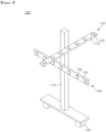
- FIG. 1 to FIG. 3 are exemplary views of a sterilizing device according to a first embodiment of the present disclosure.
- FIG. 1 is a perspective view of the sterilizing device 100 according to the first embodiment of the present disclosure.
- FIG. 2 is a side view of the sterilizing device 100 according to the first embodiment of the present disclosure.
- the sterilizing device 100 includes a main frame 110 and a sterilization unit.
- the main frame 110 extends in a vertical direction.
- the main frame 110 supports the sterilization unit with a space between the sterilization unit and the floor. In this way, the main frame 110 allows germicidal light emitted from the sterilization unit to be efficiently delivered to a sterilization target.
- the sterilization target may be a specific object.
- the sterilization target may be a space in which the sterilizing device 100 is located.
- the main frame 110 may have a vertically elongated shape.
- the sterilizing device 100 may include multiple sterilization units.
- the multiple sterilization units may be mounted on the main frame 110.
- Each of the multiple sterilization units includes a support member and a germicidal light source mounted on the support member.
- the germicidal light source may be, for example, a light emitting diode chip or a light emitting diode package.
- the support member has an elongated shape and is secured to the main frame 110.
- the support member is horizontally secured to the main frame 110.
- the support member is adapted to horizontally arrange multiple germicidal light sources thereon and may be formed of any material that can support the multiple germicidal light sources.
- the support member may be a substrate with a circuit pattern formed thereon.
- power can be supplied to the multiple germicidal light sources through the circuit pattern of the support member.
- a separate substrate or cable may be mounted on the support member to supply power to the germicidal light sources therethrough.
- At least one of the multiple support members may be positioned non-parallel to the other support members.
- the sterilization unit may include a first sterilization unit 120 and a second sterilization unit 130.
- the sterilization unit is described as including the first sterilization unit 120 and the second sterilization unit 130, the first sterilization unit 120 and the second sterilization unit 130 are different only in that respective support members of the sterilization units face in different directions from each other.
- characteristics of one of the first sterilization unit 120 and the second sterilization unit 130 can be equally applied to the other one.
- the first sterilization unit 120 may include a first support member 121 and multiple first germicidal light sources 122
- the second sterilization unit 130 may include a second support member 131 and multiple second germicidal light sources 132.
- the first support member 121 and the second support member 131 may be identical to each other except that the first support member 121 and the second support member 131 face in different directions from each other.
- first germicidal light source 122 and the second germicidal light source 132 may be identical to each other.
- a germicidal light source mounted on the first support member 121 is referred to as the first germicidal light source 122
- a germicidal light source mounted on the second support member 131 is referred to as the second germicidal light source 132.
- Both the first support member 121 and the second support member 131 may be horizontally secured to the main frame 110.
- first support member 121 and the second support member 131 may disposed to cross each other.
- the germicidal light source emits germicidal light to sterilize a sterilization target.
- the germicidal light may be any wavelength of light that can inactivate microorganisms.
- the germicidal light may be light having germicidal power, such as blue light and UV light.
- UVC is known to have high germicidal capability.
- the sterilizing device 100 illuminates a sterilization target with the germicidal light at an intensity greater than or equal to a minimum intensity required for sterilization.
- the first germicidal light source 122 may be mounted on both surfaces of the first support member 121, and the second germicidal light source 132 may be mounted on both surfaces of the second support member 131.
- the first support member 121 may be disposed such that the opposite surfaces thereof having the respective first germicidal light sources 122 mounted thereon face in upward and downward directions of the main frame 110, respectively. That is, one side surface of the first support member 121, which is connected between the opposite surfaces having the respective first germicidal light sources 122 mounted thereon, may be secured to the main frame 110.
- the second support member 131 may be disposed such that the opposite surfaces thereof having the respective second germicidal light sources 122 mounted thereon face in opposite lateral directions of the main frame 110, respectively. That is, one of the opposite surfaces of the second support member 131 having the respective second germicidal light sources 122 mounted thereon may be partially secured to the main frame 110.
- Each of the first sterilization unit 120 and the second sterilization unit 130 may include a connection member 160.
- connection member 160 of the first sterilization unit 120 may connect the first support member 121 to the main frame 110.
- connection member 160 of the second sterilization unit 130 may connect the second support member 131 to the main frame 110. That is, the connection member 160 of the first sterilization unit 120 is connected at one end thereof to the main frame 110 and is connected at the other end thereof to the first support member 121.
- connection member 160 of the second sterilization unit 130 is connected at one end thereof to the main frame 110 and is connected at the other end thereof to the second support member 131.
- connection member 160 of the second sterilization unit 130 may allow the main frame 110 to be spaced apart from the second support member 131, as shown in FIG. 2 .
- connection member 160 of the first sterilization unit 120 may allow the main frame 110 to be spaced apart from the second support member 131.
- the sterilizing device 100 may change a travel direction of the germicidal light through adjustment of angles of the first sterilization unit 120 and the second sterilization unit 130.
- each of the first sterilization unit 120 and the second sterilization unit 130 is adjustable in angle with respect to a longitudinal direction of the main frame 110.
- each of the first sterilization unit 120 and the second sterilization unit 130 is movable along a side periphery of the main frame.
- each of the first sterilization unit 120 and the second sterilization unit 130 is pivotally coupled to the main frame 110.
- the sterilizing device 100 can be carried in compact form with the first sterilization unit 120 and the second sterilization unit 130 pivoted to be parallel to the main frame 110, as shown in FIG. 3 .
- Adjustment of the angles of the first sterilization unit 120 and the second sterilization unit 130 may be performed through the first support member 121 and the second support member 131 or through the connection member 160.
- adjustment of the angles of the first sterilization unit 120 and the second sterilization unit 130 may be implemented by any angle adjustment technique known in the art, without limitation.
- the sterilizing device can provide efficient sterilization regardless of the location of a sterilization target.
- the sterilizing device can provide efficient sterilization through adjustment of the angles of the first sterilization unit 120 and the second sterilization unit 130 depending on the shape of a space to be sterilized.
- the sterilizing device 100 can deliver the germicidal light in all directions with respect to the main frame 110. That is, the sterilizing device 100 according to this embodiment can increase the area illuminated by the germicidal light, as compared with conventional sterilizing devices.
- connection member 160 each of the first sterilization unit 120 and the second sterilization unit 130 is described as including the connection member 160 in this embodiment, it will be understood that the present disclosure is not limited thereto and the connection member 160 may be omitted.
- the sterilizing device 100 may include a moving member 140.
- the moving member 140 is disposed on an underside of the main frame 110 and helps to move the sterilizing device 100.
- the moving member 140 may include a wheel.
- the present disclosure is described with reference to an example in which the moving member 140 includes a wheel, it will be understood that the present disclosure is not limited thereto and the moving member 140 may be anything that can help to move the sterilizing device 100.
- the sterilizing device 100 according to this embodiment can be easily moved from space to space. Since the sterilizing device 100 according to this embodiment can be moved to a space in need of sterilization, there is no need to install the sterilizing device in each space. Thus, the sterilizing device 100 according to this embodiment can provide high cost saving benefits, as compared with conventional built-in sterilization devices.
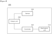
- FIG. 4 is an exemplary view of a sterilizing device according to a second embodiment.
- the sterilizing device 200 according to the second embodiment may further include a sensor 230 and a controller 220 besides the components of the sterilizing device according to the first embodiment.
- the sensor 230 detects a person or an object in a space to be sterilized. That is, with the sensor 230, the sterilizing device 200 according to this second embodiment can detect the presence/absence of a person in a space in which sterilization is performed.
- the sensor 230 may include an ultrasonic sensor, an image sensor, an optical sensor, a pressure sensor, and the like.
- the sensor 230 may include any type of sensor that can detect a sterilization target in a space to be sterilized, such as a chemical sensor, a biosensor, and a temperature sensor.
- the controller 220 may control operation of the sterilization unit 210 based on signals received from the sensor 230.
- the controller 220 may control the sterilization unit 210 to stop emission of the germicidal light in response to a signal from the sensor 230.
- the senor 230 when the sensor 230 detects a person in a space to be sterilized, the sensor 230 transmits a signal corresponding thereto to the controller 220.
- the controller 220 stops sterilization operation of the sterilization unit 210 in response to the signal from the sensor 230.
- the senor 230 transmits a signal corresponding thereto to the controller 220.
- the controller 220 controls the sterilization unit 210 to resume emission of the germicidal light in response to the signal from the sensor 230.
- the sterilizing device 200 may further include an output unit 240 displaying detection of an object by the sensor 230.
- the output unit 240 may be operated in response to a signal from the sensor 230, or may be operated in response to a signal from the controller 220.
- the sterilizing device 200 can prevent a person or an animal from being exposed to the germicidal light through detection of movement of a person or an animal.
- FIG. 5 and FIG. 6 are exemplary views of a sterilizing device according to a third embodiment of the present disclosure.
- FIG. 5 is a perspective view of the sterilizing device 300 according to the third embodiment
- FIG. 6 is a side view of the sterilizing device 300 according to the third embodiment.
- the sterilizing device 300 includes a main frame 110, a sterilization unit, and a moving member 140.
- the main frame 110 extends in the vertical direction and serves to support the sterilization unit.
- the sterilization unit includes a first sterilization unit 320 and a second sterilization unit 330.
- Each of the first sterilization unit 320 and the second sterilization unit 330 has a horizontally elongated shape.
- the first sterilization unit 320 includes a first support member 321 and multiple germicidal light sources 310 mounted on the first support member 321.
- the second sterilization unit 330 includes a second support member 331 and multiple germicidal light sources 310 mounted on the second support member 331.
- the germicidal light source 310 is disposed on a lower surface of each of the first support member 321 and the second support member 331.
- the germicidal light source 310 may emit light in a downward direction of the sterilizing device 300.
- the first support member 321 and the second support member 331 have an elongated shape and are disposed side by side with the main frame 110 interposed therebetween.
- each of the first support member 321 and the second support member 331 are movable up and down with a side surface of each of the first support member 321 and the second support member 331 partially secured to a vertical member.
- Both longitudinal ends of each of the first support member 321 and the second support member 331 may form multiple mounting portions 301. At least one germicidal light source 310 may be mounted on each of the multiple mounting portions 301.
- the multiple mounting sections 301 may be bendable to various angles.
- the germicidal light can reach farther depending on bending angles of the mounting portions 301 of the first support member 321 and the second support member 331.
- the germicidal light can be delivered laterally as well as downward depending on the bending angle of the mounting sections 301 of the first support member 321 and the second support member 331.
- FIG. 7 is an exemplary view illustrating an illumination range of a sterilizing device including a flat support member.
- the sterilizing device 10 of FIG. 7 due to the flat shape of the support member, all germicidal light sources 12 emit light toward a bottom of a space to be sterilized. That is, the sterilizing device 10 can illuminate only a portion of the bottom of the space to be sterilized. Conversely, the sterilizing device 300 according to this embodiment can deliver the germicidal light laterally as well as downward with the germicidal light sources 310 disposed only on one surface of each of the first support member 321 and the second support member 331, as shown in FIG. 6 .
- a region illuminated by each germicidal light source can be varied depending on the bending angle of the support member.
- the sterilizing device 300 can increase sterilization area through adjustment of the bending angle of the support member.
- the germicidal light is shown as not being delivered to some regions of the space to be sterilized.
- the sterilizing device 300 according to this embodiment can illuminate the entire region of the space to be sterilized through adjustment of the bending angle of the support member and the number of germicidal light sources.
- the germicidal light can be delivered over a larger area.
- the sterilizing device 300 can illuminate a large area with the germicidal light using a small number of germicidal light sources through adjustment of the bending angles of the opposite ends of each of the first support member 321 and the second support member 331.
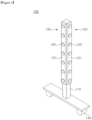
- FIG. 8 and FIG. 9 are exemplary views of a sterilizing device according to a fourth embodiment of the present disclosure.
- the sterilizing device 400 includes a main frame 110, a sterilization unit, and a moving member 140.
- the sterilization unit may be a sterilizing module including at least one germicidal light source 410.
- the sterilization unit includes a first sterilization units 420, a second sterilization units 430, and a third sterilization unit 450.
- the sterilizing device 400 has a structure in which sterilization units are disposed at fours sides of the main frame 110, respectively.
- the first sterilization unit 420 includes a first support member 121, a germicidal light source 410, a connection member 460, and a first securing member 470.
- the second sterilization unit 420 includes a second support member 131, a germicidal light source 410, a connection member 460, and a first securing member 470.
- connection member 460 of the first sterilization unit 420 is connected at one end thereof to the main frame 110 and is connected at the other end thereof to the first support member 121.
- connection member 460 of the second sterilization unit 430 is connected at one end thereof to the main frame 110 and is connected at the other end thereof to the second support member 131.
- connection member 460 extends from a side surface of the main frame 110.
- the first sterilization unit 420 and the second sterilization unit 430 can deliver the germicidal light farther away from the main frame 110.
- first securing members 470 are mounted on each of the first support member 121 and the second support member 131.
- Multiple germicidal light sources 410 are mounted on respective first securing members 470 of each of the first support member 121 and the second support member 131.
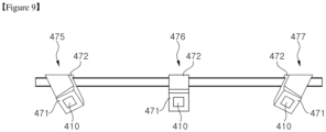
- the first securing member 470 includes a first mounting surface 471 on which the germicidal light source 410 is mounted and a first securing portion 472 secured to the first support member 121 or the second support member 131.
- the first securing member 470 has a bent shape such that the first securing portion part 472 surrounds the first support member 121 or the second support member 131.
- the present disclosure is not limited thereto and the first securing portion 472 of the first securing member 470 may have any shape that allows the first securing portion 472 to be stably secured to the first support member 121 or the second support member 131.
- the first mounting surface 471 is tilted downward at a predetermined angle outwardly of the main frame 110.
- At least one of the multiple first securing members 470 mounted on one support member is tilted in a different direction than the other first securing members 470.
- first securing members 470 may be mounted on each of the first support member 121 and the second support member 131.
- the three first securing members 470 may be referred to as a 1 st first securing member 475, a 2 nd first securing member 476, and a 3 rd first securing member 477, respectively.
- the 2 nd first securing member 476 and the 3 rd first securing member 477 are disposed at opposite sides of the 1 st first securing member 475. Referring to FIG. 9 , the first mounting surface 471 of the 2 nd first securing member 476 and the first mounting surface 471 of the 3 rd first securing member 477 are tilted at a predetermined angle in opposite directions with respect to the first mounting surface 471 of the 1 st first securing member 475.
- the germicidal light sources mounted on the 2 nd first securing member 476 and the 3 rd first securing member 477 can deliver the germicidal light toward a space located outwardly of a corner of the main frame 110.
- the germicidal light sources 410 can deliver the germicidal light in different directions from one another, whereby a larger area can be illuminated with the germicidal light.
- the sterilizing device 400 can reduce overlap in illumination between adjacent germicidal light sources 410, as compared with when the light exit surfaces of the respective germicidal light sources 410 face in the same direction.
- the sterilizing device 400 according to this embodiment can improve uniformity of illumination with the germicidal light, as compared with when the light exit surfaces of the respective germicidal light sources 410 face in the same direction. That is, the sterilizing device 400 according to the present embodiment can improve irradiance uniformity across the entire sterilization target through minimization of overlap in illumination between adjacent germicidal light sources 410.
- the sterilizing device 400 can also deliver the germicidal light to corners of a space to be sterilized, which would otherwise be generally unreachable by the germicidal light.
- the first securing member 470 may include a component for supplying power to the germicidal light source 410.
- the first securing member 470 may include a circuit board formed with an interconnect electrically connected to the germicidal light source 410.
- the first securing member 470 may include a cable connected to the germicidal light source 410.
- the third sterilization unit 450 includes a second securing member 480 and a germicidal light source 410 mounted on the second securing member 480.
- the third sterilization unit 450 is mounted on each side surface of the main frame 110. However, it will be understood that the third sterilization unit 450 is not necessarily mounted on the main frame 110.
- the third sterilization unit 450 may be mounted on the connection member 460.
- the third sterilization unit 450 is shown as being disposed above the connection member 460, it will be understood that the present disclosure is not limited thereto and the third sterilization unit 450 may be disposed below the connection member 460. Further, the third sterilization unit 460 may be disposed between the connection members 460 to deliver the germicidal light through a space between the first sterilization unit 420 and the second sterilization unit 430.
- the second securing member 480 includes a second mounting surface 481 on which the germicidal light source 410 is mounted and a second securing portion 482 secured to the main frame 110.
- the second securing member 480 is coupled at one end thereof to a side surface of the main frame 110.
- the one end of the second securing member 480 corresponds to the second securing portion 482.
- the second fixing portion 482 is simply shown as adjoining the side surface of the main frame 110.
- the present disclosure is not limited thereto and the second securing portion 482 may have any structure that allows the second securing portion 482 to be secured to the main frame 110.
- a portion of the other end of the second securing member 480 is tilted upward at a predetermined angle with respect to a body of the second securing member 480.
- a lower surface of the inclined portion corresponds to the second mounting surface 481.
- the second mounting surface 481 faces sideways with respect to the main frame 110 and is tilted downward at a predetermined angle.
- the germicidal light source 410 mounted on the second mounting surface 481 emits the germicidal light diagonally toward a region under the sterilization unit. In this way, the germicidal light source 410 can deliver the germicidal light over a larger area.
- the second securing member 480 may include a component for supplying power to the germicidal light source 410.
- the sterilizing device 400 can deliver the germicidal light to regions far away from the main frame 110.
- the sterilizing device 400 can deliver the germicidal light to a region between the main frame 110 and the first sterilization unit 420 or the second sterilization unit 430.
- the sterilizing device 400 can uniformly deliver the germicidal light over a large area.
- Table 1 shows the position and angle of each germicidal light source 410 according to this embodiment.
- Table 1 Position of germicidal light source (m) Angle of germicidal light source (deg.) X Y Z (height) ⁇ ⁇ ⁇ Germicidal light source on 1 st first securing member 0.8 0.0 2.0 - -65 - Germicidal light source on second securing member 0.1 0.0 2.0 - -50 - Germicidal light source on 2 nd first securing member 0.8 0.4 1.9 - -60 -55 Germicidal light source on 3 rd first securing member 0.8 -0.4 2.0 - -60 55
- the germicidal light sources 410 shown in Table 1 are germicidal light sources 410 disposed at one side of the main frame 110.
- a set of germicidal light sources 410 as shown in Table 1 is disposed at each of the four sides of the main frame 110. Assuming each germicidal light source 410 includes one light emitting diode, a total of 16 light emitting diodes is used in the sterilizing device 400 according to this embodiment.
- the present disclosure has been described with reference to an example in which the sterilization units of the sterilizing device 400 according to this embodiment are connected to the main frame 110 through respective connection members 460.
- the present disclosure is not limited thereto and the sterilizing device 300 according to this embodiment may have a different structure.
- first sterilization unit 420 and the second sterilization unit 430 may be connected to a common connection member 460.
- the sterilizing device 400 may include two connection members 460 connected to the main frame 110.
- Each of the connection members 460 may be connected at one end thereof to the first sterilization unit 420 and the second sterilization unit 430 and may be connected at the other end thereof to the main frame 110.
- One end of the support member 121 of the first sterilization unit 420 and one end of the support member 131 of the second sterilization unit 430 may be connected to the one end of the connection member 460.
- the first sterilization unit 420 and the second sterilization unit 430 may be disposed to face in opposite directions and to be symmetrical with respect to the one end of the connection member 460.
- each of the first sterilization unit 420 and the second sterilization unit 430 may be moved outwardly or inwardly of the connection member 430. That is, in the sterilizing device 400, the sterilization unit may be folded or unfolded with respect to the connection member 460.
- connection members 460 may also be folded or unfolded with respect to the main frame 110.
- the main frame 110 is adjustable in length. Further, these motions of the sterilizing device 400 may be automatically performed to improve user convenience.
- the sterilizing device 400 can be carried or stored in compact form with the sterilization units and the connection member 460 folded and the main frame minimized in length.
- FIG. 10 shows comparison in light distribution between a conventional sterilizing device and the sterilizing device according to this embodiment.
- FIG. 10A shows a light distribution produced by the conventional sterilizing device and FIG. 10B shows a light distribution produced by the sterilizing device according to this embodiment.
- FIG. 10C shows a light distribution produced by four sterilizing devices according to this embodiment disposed around the center of a space to be sterilized.
- light distribution refers to a distribution of the germicidal light delivered to the space to be sterilized by each of the sterilizing devices.
- the graphs of FIG. 10 show irradiance levels of the germicidal light, as measured along the X-axis from the center of the space to be sterilized.
- the conventional sterilizing device ( FIG. 10A ) includes a sterilization unit located 2 m above the floor, wherein light exit surfaces of respective germicidal light sources of the sterilization unit face in the same direction.
- the sterilizing device includes a sterilization unit including germicidal light sources disposed as shown in FIG. 8 and Table 1. That is, in the sterilizing device of FIG. 10B , respective light exit surfaces of the germicidal light sources face in different directions from one another such that the germicidal light sources emit the germicidal light in different directions from one another.
- FIG. 10C four sterilizing devices, identical to the sterilizing device of FIG. 8 , are disposed in the space to be sterilized.
- the four sterilizing devices are disposed in four sections around the center of the space to be sterilized, respectively.
- one sterilizing device is spaced 4 m apart from adjacent sterilizing devicees.
- the sterilization units of the sterilizing devices of FIG. 10B and FIG. 10C are also located 2 m above the floor.
- FIG. 10A and FIG. 10B show simulation results for a space having an area of 25 m 2 (5 m ⁇ 5 m (width ⁇ length)), and FIG. 10C shows simulation results for a space having an area of 100 m 2 (10 m ⁇ 10 m (width ⁇ length)).
- the sterilizing device used in the simulations, has a length of about 1.6 m, wherein the length is a distance between opposite horizontal ends thereof.
- the simulation results are irradiances measured at the bottom of the space to be sterilized.
- the regions marked in red and green are regions illuminated with a sufficient amount of the germicidal light for sterilization. That is, A1, B1, and C1 are regions than can be sterilized to a sufficient degree.
- the regions marked in blue are regions illuminated with an insufficient amount of the germicidal light for sterilization.
- the blue regions are located outside A1, B1, and C1.
- intensity of the germicidal light is high only in a central region of the space to be sterilized and decreases sharply as distance from the central region increases. That is, the graph of FIG. 10A shows that the conventional sterilizing device exhibits poor overall illumination uniformity. In this case, most regions, except for the central region close to the germicidal light sources, cannot be properly sterilized. In particular, corner regions are supplied with little or no germicidal light.
- the sterilizing device according to this embodiment can deliver a sufficient amount of germicidal light for sterilization over a large area, as compared with the conventional sterilizing device.
- the sterilizing device according to this embodiment provides uniform light distribution, as compared with the conventional sterilizing device.
- a deviation in irradiance across regions of the space to be sterilized is less than 50% of a maximum irradiance. That is, a difference between an average irradiance across the regions of the space to be sterilized and a maximum irradiance is less than 50% of the maximum irradiance. Accordingly, it can be seen that the sterilizing device according to this embodiment can ensure uniform irradiance across the regions of the space to be sterilized.
- the sterilizing device according to this embodiment achieves a uniformity of illumination of 75% or more across the regions of the space to be sterilized. That is, it can be seen that the sterilizing device according to this embodiment can ensure uniform illumination over a large area, as compared with the conventional sterilizing device.
- the sterilizing device according to this embodiment can illuminate corner regions with the germicidal light at high intensity, as compared with the conventional sterilizing device.
- the results in FIG. 10 show that the sterilizing device according to this embodiment can uniformly illuminate a large area with the germicidal light at a high intensity, as compared with the conventional sterilizing device.
- the sterilizing device according to this embodiment can deliver the germicidal light throughout the space to be sterilized, including corner regions, which are supplied with little or no germicidal light by the conventional sterilizing device.
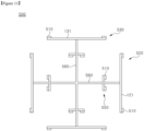
- FIG. 11 is a schematic plan view of a sterilizing device according to a fifth embodiment of the present disclosure.
- the sterilizing device 500 includes a pair of first sterilization units 520, a pair of second sterilization units 530, and multiple third sterilization units 550.
- the sterilizing device 500 may further include a main frame and a moving member.
- the first sterilization unit 520, the second sterilization unit 530, and the third sterilization unit 550 may have substantially the same structure as the sterilization units according to the above embodiments. In this embodiment, description will be made mainly on differences from the above embodiments in terms of arrangement of germicidal light sources 510 of each sterilization unit.
- the first sterilization unit 520 has a structure in which two germicidal light sources 510 are mounted at opposite ends of a first support member 121, respectively.
- the second sterilization unit 530 has a structure in which two germicidal light sources 510 are mounted at opposite ends of the second support member 131, respectively.
- each of the first sterilization unit 520 and the second sterilization unit 530 is shown as including only the two germicidal light sources 510 mounted at the opposite ends of the support member, it will be understood that the present disclosure is not limited thereto and each of the first sterilization unit 520 and the second sterilization unit 530 may further include a germicidal light source 510 mounted at the center of the support member, as shown in FIG. 8 .
- the multiple third sterilization units 550 are mounted on respective connection members 560.
- the third sterilization unit 550 has a structure in which two germicidal light sources 510 are mounted at opposite ends of a horizontally elongated support member, respectively.
- the third sterilization unit 550 may have the same structure as the third sterilization unit of FIG. 8 except that the third sterilization unit 550 is mounted on the connection member 560.
- the third sterilization unit 550 may be disposed midway between the main frame 110 and the support member to emit the germicidal light to a space between the main frame 110 and the support member.
- the germicidal light sources 510 of the third sterilization unit 550 may be disposed between the two germicidal light sources 510 of the first sterilization unit 520 or the second sterilization unit 530. In this way, the third sterilization unit 550 can deliver the germicidal light to a region corresponding to the center of the first sterilization unit 520 or the second sterilization unit 530, which would otherwise be likely to be supplied with a relatively insufficient amount of light, as compared with regions corresponding to the opposite ends of the first sterilization unit 520 or the second sterilization unit 530.
- the third sterilization unit 550 is mounted on the connection member 560 to be movable along the connection member 560. That is, the third sterilization unit 550 can be moved between the main frame 110 and the support member along the connection member 560 to deliver the germicidal light to a region in short supply of the germicidal light.
- the germicidal light sources 510 of each of the first sterilization unit 520, the second sterilization unit 530, and the third sterilization unit 550 may be mounted on the support member to face sideways or downwards. Alternatively, the germicidal light sources 510 may be mounted on the support member to face in different directions.
- each of the first sterilization unit 520, the second sterilization unit 530, and the third sterilization unit 550 may be adjustable in angle with respect to the vertical direction.
- each of the sterilization units may be individually adjustable in angle with respect to the vertical direction.
- the sterilizing device 500 can uniformly deliver the germicidal light throughout a space to be sterilized through adjustment of the angles of the first sterilization unit 520, the second sterilization unit 530, and the third sterilization unit 550 or movement of the third sterilization unit 550.
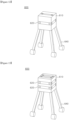
- FIG. 12 and FIG. 13 are exemplary views of a sterilizing device according to a sixth embodiment of the present disclosure.
- the sterilizing device 600 includes a main frame 610, a sterilization unit 620, and a moving member 640.
- the main frame 610 has a cuboidal shape.
- the sterilization unit 620 includes multiple sterilization units disposed on the upper surface and four side surfaces of the main frame 610, respectively.
- the moving member 640 includes a wheel to facilitate movement of the sterilizing device 600.
- the moving member 640 has an elongated shape and supports the main frame 610 with a space between the main frame 610 and the floor.
- the sterilization unit 620 mounted on the main frame 610 can be located at an upper portion of a space to be sterilized rather than at a bottom of the space and thus can deliver the germicidal light over a large area.
- the sterilizing device 600 may further include a sterilization unit 620 mounted on a lower surface of the main frame 610.
- the sterilization unit 620 mounted on the lower surface of the main frame 610 can deliver the germicidal light to the region under the main frame 610.
- the sterilizing device 600 allows adjustment of the number of sterilization units 620 as necessary.
- the main frame 610 of the sterilizing device 600 has a cuboidal shape, rather than an elongated rod-like shape as in the above embodiments, the main frame 610 can secure a large surface area for mounting the sterilization unit 620.
- an additional sterilization unit 620 may be disposed on each surface of the main frame 610, as needed.
- sterilization units 620 are disposed on each surface of the main frame 610 in FIG. 12 and FIG. 13 , it will be understood that the present disclosure is not limited thereto and a different number of sterilization units 620 may be disposed on each surface of the main frame 610, as needed.
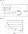
- FIG. 14 is a schematic block diagram of a sterilizing device according to a seventh embodiment of the present disclosure.
- the sterilizing device 700 according to the seventh embodiment may further include an input unit 710, a sensor 720, a calculation unit 730, a timer 740, and a controller 750, besides the components of each of the sterilizing devices according to the above embodiments.
- the input unit 710 and the sensor 720 may be disposed outside a body of the sterilizing device 700.
- the calculation unit 730, the timer 740, and the controller 750 may be disposed inside the body of the sterilizing device 700.
- the sterilizing device 700 according to the seventh embodiment may have the same external shape as any of the sterilizing devices according to the first to sixth embodiments.
- description given for the sterilizing devices according to the above embodiments can be used.
- the input unit 710 is adapted to input signals therethrough.
- the sensor 720 detects an object in a space to be sterilized and measures a distance to the object.
- the calculation unit 730 calculates conditions under which the sterilizing device 700 performs sterilization, such as sterilization time and intensity of the germicidal light, in response to signals from the input unit 710 and the sensor 720.
- the timer 740 receives information about sterilization time from the input unit 710 or the calculation unit 730 and transmits a signal corresponding to the information to the controller 750.
- the controller 750 controls operation of the sterilization unit 760 based on signals from at least one of the sensor 720, the calculation unit 730, and the timer 740.
- the sterilizing device 700 may receive an external setting signal via the input unit 710.
- the setting signal may be a sterilization time signal containing information about sterilization time.
- a user may input sterilization time to the sterilizing device 700 via the input unit 710.
- the input unit 710 may include any input device that can be used to input information, such as a button or a touchpad.
- the input unit 710 may transmit the sterilization time signal containing information about the input sterilization time to the calculation unit 730.
- the input unit 710 may transmit the sterilization time signal to both the calculation unit 730 and the timer 740.
- the sensor 720 may include at least one sensor.
- the sensor 720 may include a first sensor 721 and a second sensor 722.
- the first sensor 721 may be a sensor that detects an object within a predetermined range of distances from the sterilizing device 700.
- the first sensor 721 may be an object detection sensor.
- the first sensor 721 may generate a first sterilization termination signal upon detecting movement of an object in a space to be sterilized.
- the movement of the object may be movement of a person or an animal.
- the first sensor 721 may transmit the generated first sterilization termination signal to the controller 750.
- the first sensor 721 may transmit a first sterilization start signal to the controller 750 upon detecting that the detected object has left the space to be sterilized.
- the controller 750 may shut off power supply to the sterilization unit 760 in response to the first sterilization termination signal from the first sensor 721.
- controller 750 may initiate power supply to the sterilization unit 760 in response to the first sterilization start signal from the first sensor 721.
- the sterilizing device 700 can stop sterilization when a person or an animal enters a space where sterilization is in progress. Accordingly, the sterilizing device 700 can prevent a person or an animal from being exposed to the germicidal light.
- the second sensor 722 may include a distance sensor that measures a distance to a sterilization target.
- the distance sensor may measure distances to walls defining the space. That is, the second sensor 722 may measure the size of a space to be sterilized.
- the second sensor 722 may generate a sterilization distance signal containing information about the measured distance to the sterilization target.
- the second signal may transmit the generated sterilization distance signal to the calculation unit 730.
- the calculation unit 730 may receive the sterilization time signal from the input unit 710 and may receive the sterilization distance signal from the second sensor 722.
- the calculation unit 730 may calculate information necessary for sterilization based on the information about the sterilization time and the information about the distance to the sterilization target, which are contained in the respective received signals.
- FIG. 15 is a graph showing changes in intensity depending on travel distance of the germicidal light.
- FIG. 16 is a graph showing changes in sterilization time depending on travel distance of the germicidal light.
- FIG. 17 is a graph showing changes in sterilization time depending on intensity of the germicidal light.
- Results in FIG. 15 show that intensity of the germicidal light delivered to a sterilization target is inversely proportional to the square of a travel distance of the germicidal light.
- Results in FIG. 16 show that required sterilization time increases with increasing travel distance of the germicidal light.
- Results in FIG. 17 show that intensity of the germicidal light incident on a surface of the sterilization target is inversely proportional to sterilization time.
- T D ⁇ r 2 ⁇ 1 / ⁇ ⁇ 1 / P 0
- Equation 4 From Equation 4, it is possible to know relations between travel distance of the germicidal light, sterilization time, intensity of the germicidal light required for sterilization, and light power of the germicidal light sources.
- Equation 4 it is possible to know relations between light power of the germicidal light sources, sterilization time, intensity of the germicidal light required for sterilization, and travel distance of the germicidal light.
- I is an intensity (unit: mW/cm 2 ) of the germicidal light incident per unit surface area of the sterilization target
- P 0 is a light power (unit: mW) of the germicidal light sources
- T is an amount (unit: sec) of sterilization time
- D is a dose (unit: mJ/cm 2 ) of the germicidal light delivered per unit surface area of the sterilization target
- r is a distance (unit: cm) to the sterilization target (travel distance)
- ⁇ is an experimental constant.
- the experimental constant is a value determined through experiments on relations between the light power (P 0 ) of the germicidal light sources and the intensity (I) of the germicidal light incident on the surface of the sterilization target.
- the calculation unit 730 may calculate various types of information necessary for sterilization based on information calculated according to Equations 1 to 5.
- the calculation unit 730 may calculate an intensity of the germicidal light required to sufficiently sterilize a space to be sterilized based on the information about the distance to the sterilization target, which is received from the second sensor 722.
- the calculation unit 730 may transmit a sterilization intensity signal containing information about the calculated intensity of the germicidal light to the controller 750.
- the calculation unit 730 may transmit the sterilization time signal received from the input unit 710 to the timer 740.
- the timer 740 may receive the sterilization time signal from the input unit 710 or the calculation unit 730.
- the timer 740 may transmit a second sterilization start signal and a second sterilization termination signal to the controller 750 based on the received sterilization time signal.
- the controller 750 may receive the sterilization intensity signal from the calculation unit 730 and may receive the second sterilization start signal and the second sterilization termination signal from the timer 740.
- the controller 750 may control the amount of current supplied to the sterilization unit 760 based on the sterilization intensity signal received from the calculation unit 730. That is, the controller 750 may control the intensity of the germicidal light emitted from the sterilization unit 760 through control over the amount of current supplied to the sterilization unit 760.
- controller 750 may initiate power supply to the sterilization unit 760 in response to the second sterilization start signal from the timer 740. Further, the controller 750 may shut off power supply to the sterilization unit 760 in response to the second sterilization termination signal from the timer 740.
- the sterilizing device 700 can automatically adjust the intensity of the germicidal light based on the measured distance to the sterilization target to complete sterilization in the input sterilization time.
- intensity of the germicidal light may be set via the input unit 710.
- the calculation unit 730 may calculate sterilization time based on the intensity of the germicidal light set via the input unit 710.
- the calculation unit 730 may transmit a sterilization time signal containing information about the calculated sterilization time to the timer 740.
- the timer 740 may transmit the second sterilization start signal and the second sterilization termination signal to the controller 750 based on the sterilization time signal received from the calculation unit 730.
- the controller 750 may initiate or shut off power supply to the sterilization unit 760 in response to the second sterilization start signal or the second sterilization termination signal received from the timer 740. That is, the controller 750 may control the time the sterilization unit 760 starts or stops operation in response to the second sterilization start signal or the second sterilization termination signal.
- the controller 750 may receive information about the intensity of the germicidal light from the input unit 710 or the calculation unit 730. Accordingly, the controller 750 may control operation of the sterilization unit 760 in response to the signals from the timer 740 while controlling the intensity of the germicidal light through control over the amount of current supplied to the sterilization unit 760.
- the sterilizing device 700 may automatically calculate sterilization time and may perform sterilization for the calculated sterilization time.
- the calculation unit 730 may calculate sterilization time based on the information about the distance to the sterilization target, which is received from the second sensor 722.
- the calculation unit 730 can calculate sterilization time required for sterilization based on the distance to the sterilization target and the preset basic intensity of the germicidal light.
- the calculation unit 730 may generate a sterilization time signal and may transmit the generated sterilization time signal to the timer 740.
- the sterilizing device 700 can perform efficient sterilization through automatic calculation of sterilization time, sterilization intensity, sterilization range, and the like, based on input information.
Landscapes
- Health & Medical Sciences (AREA)
- Epidemiology (AREA)
- Life Sciences & Earth Sciences (AREA)
- Animal Behavior & Ethology (AREA)
- General Health & Medical Sciences (AREA)
- Public Health (AREA)
- Veterinary Medicine (AREA)
- Apparatus For Disinfection Or Sterilisation (AREA)
Abstract
Description
- Embodiments of the present disclosure relate to a sterilizing module and a sterilizing device including the same.
- Recently, with spread of viruses that threaten human health, such as COVID-19, efforts are being made to kill the viruses to protect humans from infection.
- In particular, a sterilization luminaire capable of sterilizing a living space, such as a house and an office, has recently been in the spotlight.
- However, such a sterilization luminaire is generally a built-in product, which is not portable from space to space. Accordingly, many built-in sterilization luminaires are needed to sterilize each space, thus resulting in increased expenses.
- Further, a general portable sterilization device is intended to sterilize a specific object with germicidal light and thus provides a small range of illumination. Accordingly, such a portable sterilization device is not suitable for sterilizing the entire region of a living space such as a house and an office.
- The above information disclosed in this Background section is only for understanding of the background of the inventive concepts, and, therefore, it may contain information that does not constitute prior art.
- Embodiments of the present disclosure provide a sterilizing module which can sterilize a space, and a sterilizing device including the same.
- Embodiments of the present disclosure provide a sterilizing module which can uniformly deliver germicidal light throughout a space to be sterilized, and a sterilizing device including the same.
- Embodiments of the present disclosure provide a sterilizing device which can be easily moved from space to space as necessary.
- Embodiments of the present disclosure provide a sterilizing device which can automatically control a sterilization operation.
- In accordance with one aspect of the present disclosure, there is provided a sterilizing module including a support member and multiple germicidal light sources. The multiple germicidal light sources are mounted on the support member and emit germicidal light, which is light having a wavelength capable of inactivating microorganisms. Respective light exit surfaces of the multiple germicidal light sources face in different directions from one another. The sterilizing module illuminates a sterilization target with the germicidal light at an irradiance greater than a minimum irradiance required for sterilization.
- The sterilization unit may include a first sterilization unit and a second sterilization unit each comprising a support member and multiple germicidal light sources. In addition, the first sterilization unit and the second sterilization unit may face in different directions from one another.
- The sterilization unit may include a pair of first sterilization units spaced apart from each other and facing in opposite directions and a pair of second sterilization units spaced apart from each other and facing in opposite directions. The pair of second sterilization units may be disposed between the pair of first sterilization units.
- The sterilization unit may further include a third sterilization unit comprising germicidal light sources. Here, the third sterilization unit may be disposed between the first sterilization unit and the second sterilization unit.
- Alternatively, the third sterilization unit may be disposed above or below the first sterilization unit or the second sterilization unit.
- Respective light exit surfaces of two germicidal light sources disposed at opposite ends of the support member, among the multiple germicidal light sources, may face in opposite directions with respect to a central axis of the support member.
- The sterilization unit may further include multiple securing members each having a mounting surface on which the germicidal light source is mounted. Here, respective mounting surfaces of the multiple securing members may face in different directions from one another.
- The sterilizing module has an illumination uniformity of 75% or more.
- In accordance with another aspect of the present disclosure, a sterilizing device includes a main frame, a sterilization unit, and multiple connection members. The sterilization unit includes multiple germicidal light sources emitting germicidal light, which is light having a wavelength capable of inactivating microorganisms. The multiple connection members connect the main frame to the sterilization unit. The sterilization unit includes a first sterilization unit and a second sterilization unit each including a support member and multiple germicidal light sources. The multiple germicidal light sources are disposed on the support member with respective light exit surfaces thereof facing in different directions from one another. The sterilizing device illuminates a sterilization target with the germicidal light at an irradiance greater than a minimum irradiance required for sterilization.
- The first sterilization unit and the second sterilization unit may face in different directions from one another.
- The sterilization unit may include a pair of first sterilization units spaced apart from each other and facing in opposite directions and a pair of second sterilization units spaced apart from each other and facing in opposite directions. Here, the pair of second sterilization units may be disposed between the pair of first sterilization units.
- The sterilization unit may further include a third sterilization unit including germicidal light sources and mounted on the connection member or the main frame. Here, the third sterilization unit may be disposed between the first sterilization unit and the second sterilization unit.
- Alternatively, the third sterilization unit may be disposed above or below the first sterilization unit or the second sterilization unit.
- Respective light exit surfaces of two germicidal light sources disposed at opposite ends of the support member, among the multiple germicidal light sources, may face in opposite directions with respect to a central axis of the support member.
- The sterilization unit may further include multiple securing members each having a mounting surface on which the germicidal light source is mounted and a securing portion secured to the support member. Here, respective mounting surfaces of the multiple securing members may face in different directions from one another.
- The sterilizing device may further include an object detection sensor detecting movement of an object.
- The sterilizing device may further include a controller controlling the sterilization unit to stop emission of the germicidal light upon detection of an object by the object detection sensor.
- The sterilizing device may further include at least one of a distance sensor measuring a distance to a sterilization target and a timer transmitting a signal for controlling sterilization time to the controller.
- The sterilizing device may further include a calculation unit calculating at least one of intensity of the germicidal light and sterilization time based on at least one of information about the distance to the sterilization target and information about the sterilization time.
- The sterilizing device has an illumination uniformity of 75% or more.
- In accordance with some embodiments of the present disclosure, the sterilizing module and the sterilizing device can uniformly deliver germicidal light throughout a space to be sterilized, thereby providing improved sterilization efficiency.
- In accordance with other embodiments of the present disclosure, the sterilizing device can be moved from space to space. Thus, unlike conventional built-in sterilizing devices, the sterilizing device according to the present disclosure can eliminate the need to install one sterilizing device in each space, thereby providing cost saving benefits.
- In accordance with yet other embodiments of the present disclosure, the sterilizing device can perform efficient sterilization through automatic calculation of sterilization conditions depending on the type of spaces to be sterilized.
- The accompanying drawings, which are included to provide a further understanding of the disclosure and are incorporated in and constitute a part of this specification, illustrate exemplary embodiments of the disclosure, and together with the description serve to explain the inventive concepts.
-
FIG. 1 is exemplary view of a sterilizing device according to a first embodiment of the present disclosure. -
FIG. 2 is another exemplary view of a sterilizing device according to a first embodiment of the present disclosure. -
FIG. 3 is another exemplary view of a sterilizing device according to a first embodiment of the present disclosure. -
FIG. 4 is a schematic block diagram of a sterilizing device according to a second embodiment of the present disclosure. -
FIG. 5 is exemplary view of a sterilizing device according to a third embodiment of the present disclosure. -
FIG. 6 is another exemplary view of a sterilizing device according to a third embodiment of the present disclosure. -
FIG. 7 is a view illustrating illumination range of a sterilizing device including a flat support member. -
FIG. 8 is exemplary view of a sterilizing device according to a fourth embodiment of the present disclosure. -
FIG. 9 is another exemplary view of a sterilizing device according to a fourth embodiment of the present disclosure. -
FIG. 10 shows comparison in light distribution between a conventional sterilizing device and the sterilizing device according to the fourth embodiment. -
FIG. 11 is a schematic plan view of a sterilizing device according to a fifth embodiment of the present disclosure. -
FIG. 12 is exemplary view of a sterilizing device according to a sixth embodiment of the present disclosure. -
FIG. 13 is another exemplary view of a sterilizing device according to a sixth embodiment of the present disclosure. -
FIG. 14 is a schematic block diagram of a sterilizing device according to a seventh embodiment of the present disclosure. -
FIG. 15 is a graph showing changes in intensity depending on travel distance of germicidal light. -
FIG. 16 is a graph showing changes in sterilization time depending on travel distance of germicidal light. -
FIG. 17 is a graph showing changes in sterilization time depending on intensity of germicidal light. - Hereinafter, embodiments of the present disclosure will be described with reference to the accompanying drawings. It should be understood that the embodiments are provided for complete disclosure and a thorough understanding of the present disclosure by those skilled in the art. Therefore, the present disclosure is not limited to the following embodiments and may be embodied in different ways. In addition, the drawings may be exaggerated in width, length, and thickness of components for descriptive convenience and clarity only. Like components will be denoted by like reference numerals throughout the specification.
-
FIG. 1 to FIG. 3 are exemplary views of a sterilizing device according to a first embodiment of the present disclosure. -
FIG. 1 is a perspective view of the sterilizingdevice 100 according to the first embodiment of the present disclosure.FIG. 2 is a side view of the sterilizingdevice 100 according to the first embodiment of the present disclosure. - Referring to
FIG. 1 andFIG. 2 , the sterilizingdevice 100 according to the first embodiment includes amain frame 110 and a sterilization unit. - The
main frame 110 extends in a vertical direction. - In addition, the
main frame 110 supports the sterilization unit with a space between the sterilization unit and the floor. In this way, themain frame 110 allows germicidal light emitted from the sterilization unit to be efficiently delivered to a sterilization target. Here, the sterilization target may be a specific object. Alternatively, the sterilization target may be a space in which thesterilizing device 100 is located. - The
main frame 110 may have a vertically elongated shape. - The sterilizing
device 100 may include multiple sterilization units. The multiple sterilization units may be mounted on themain frame 110. - Each of the multiple sterilization units includes a support member and a germicidal light source mounted on the support member. The germicidal light source may be, for example, a light emitting diode chip or a light emitting diode package.
- The support member has an elongated shape and is secured to the
main frame 110. The support member is horizontally secured to themain frame 110. - The support member is adapted to horizontally arrange multiple germicidal light sources thereon and may be formed of any material that can support the multiple germicidal light sources.
- In one embodiment, the support member may be a substrate with a circuit pattern formed thereon. In this embodiment, power can be supplied to the multiple germicidal light sources through the circuit pattern of the support member.
- In another embodiment in which the support member is not formed with a circuit pattern, a separate substrate or cable may be mounted on the support member to supply power to the germicidal light sources therethrough.
- At least one of the multiple support members may be positioned non-parallel to the other support members.
- Referring to
FIG. 1 , the sterilization unit may include afirst sterilization unit 120 and asecond sterilization unit 130. Although the sterilization unit is described as including thefirst sterilization unit 120 and thesecond sterilization unit 130, thefirst sterilization unit 120 and thesecond sterilization unit 130 are different only in that respective support members of the sterilization units face in different directions from each other. - Accordingly, characteristics of one of the
first sterilization unit 120 and thesecond sterilization unit 130 can be equally applied to the other one. - The
first sterilization unit 120 may include afirst support member 121 and multiple first germicidallight sources 122, and thesecond sterilization unit 130 may include asecond support member 131 and multiple second germicidallight sources 132. As described above, thefirst support member 121 and thesecond support member 131 may be identical to each other except that thefirst support member 121 and thesecond support member 131 face in different directions from each other. - In addition, the first germicidal
light source 122 and the second germicidallight source 132 may be identical to each other. In brief, a germicidal light source mounted on thefirst support member 121 is referred to as the first germicidallight source 122, and a germicidal light source mounted on thesecond support member 131 is referred to as the second germicidallight source 132. - Both the
first support member 121 and thesecond support member 131 may be horizontally secured to themain frame 110. - Here, the
first support member 121 and thesecond support member 131 may disposed to cross each other. - The germicidal light source emits germicidal light to sterilize a sterilization target. The germicidal light may be any wavelength of light that can inactivate microorganisms. For example, the germicidal light may be light having germicidal power, such as blue light and UV light. In particular, UVC is known to have high germicidal capability.
- The sterilizing
device 100 according to this embodiment illuminates a sterilization target with the germicidal light at an intensity greater than or equal to a minimum intensity required for sterilization. - Referring to
FIG. 1 , the first germicidallight source 122 may be mounted on both surfaces of thefirst support member 121, and the second germicidallight source 132 may be mounted on both surfaces of thesecond support member 131. - The
first support member 121 may be disposed such that the opposite surfaces thereof having the respective first germicidallight sources 122 mounted thereon face in upward and downward directions of themain frame 110, respectively. That is, one side surface of thefirst support member 121, which is connected between the opposite surfaces having the respective first germicidallight sources 122 mounted thereon, may be secured to themain frame 110. - The
second support member 131 may be disposed such that the opposite surfaces thereof having the respective second germicidallight sources 122 mounted thereon face in opposite lateral directions of themain frame 110, respectively. That is, one of the opposite surfaces of thesecond support member 131 having the respective second germicidallight sources 122 mounted thereon may be partially secured to themain frame 110. - Each of the
first sterilization unit 120 and thesecond sterilization unit 130 may include aconnection member 160. - The
connection member 160 of thefirst sterilization unit 120 may connect thefirst support member 121 to themain frame 110. In addition, theconnection member 160 of thesecond sterilization unit 130 may connect thesecond support member 131 to themain frame 110. That is, theconnection member 160 of thefirst sterilization unit 120 is connected at one end thereof to themain frame 110 and is connected at the other end thereof to thefirst support member 121. In addition, theconnection member 160 of thesecond sterilization unit 130 is connected at one end thereof to themain frame 110 and is connected at the other end thereof to thesecond support member 131. - The
connection member 160 of thesecond sterilization unit 130 may allow themain frame 110 to be spaced apart from thesecond support member 131, as shown inFIG. 2 . In addition, although not shown, theconnection member 160 of thefirst sterilization unit 120 may allow themain frame 110 to be spaced apart from thesecond support member 131. - In addition, the sterilizing
device 100 according to this embodiment may change a travel direction of the germicidal light through adjustment of angles of thefirst sterilization unit 120 and thesecond sterilization unit 130. - For example, each of the
first sterilization unit 120 and thesecond sterilization unit 130 is adjustable in angle with respect to a longitudinal direction of themain frame 110. In addition, each of thefirst sterilization unit 120 and thesecond sterilization unit 130 is movable along a side periphery of the main frame. - In addition, each of the
first sterilization unit 120 and thesecond sterilization unit 130 is pivotally coupled to themain frame 110. In this way, the sterilizingdevice 100 can be carried in compact form with thefirst sterilization unit 120 and thesecond sterilization unit 130 pivoted to be parallel to themain frame 110, as shown inFIG. 3 . - Adjustment of the angles of the
first sterilization unit 120 and thesecond sterilization unit 130 may be performed through thefirst support member 121 and thesecond support member 131 or through theconnection member 160. - In addition, adjustment of the angles of the
first sterilization unit 120 and thesecond sterilization unit 130 may be implemented by any angle adjustment technique known in the art, without limitation. - Through adjustment of the angles of the
first sterilization unit 120 and thesecond sterilization unit 130, the sterilizing device according to this embodiment can provide efficient sterilization regardless of the location of a sterilization target. In addition, the sterilizing device according to this embodiment can provide efficient sterilization through adjustment of the angles of thefirst sterilization unit 120 and thesecond sterilization unit 130 depending on the shape of a space to be sterilized. - With the
first support member 121 and thesecond support member 131 secured to themain frame 110 in a manner as shown inFIG. 1 , the sterilizingdevice 100 according to this embodiment can deliver the germicidal light in all directions with respect to themain frame 110. That is, the sterilizingdevice 100 according to this embodiment can increase the area illuminated by the germicidal light, as compared with conventional sterilizing devices. - Although each of the
first sterilization unit 120 and thesecond sterilization unit 130 is described as including theconnection member 160 in this embodiment, it will be understood that the present disclosure is not limited thereto and theconnection member 160 may be omitted. - The sterilizing
device 100 according to this embodiment may include a movingmember 140. - The moving
member 140 is disposed on an underside of themain frame 110 and helps to move thesterilizing device 100. - For example, the moving
member 140 may include a wheel. Although the present disclosure is described with reference to an example in which the movingmember 140 includes a wheel, it will be understood that the present disclosure is not limited thereto and the movingmember 140 may be anything that can help to move thesterilizing device 100. - With the moving
member 140, the sterilizingdevice 100 according to this embodiment can be easily moved from space to space. Since the sterilizingdevice 100 according to this embodiment can be moved to a space in need of sterilization, there is no need to install the sterilizing device in each space. Thus, the sterilizingdevice 100 according to this embodiment can provide high cost saving benefits, as compared with conventional built-in sterilization devices. - Next, other embodiments of the present disclosure will be described. Description of the same components as in the above embodiment will be omitted or briefly given. For details of the same components as in the above embodiment, refer to description given for the above embodiment.
-
FIG. 4 is an exemplary view of a sterilizing device according to a second embodiment. - Referring to
FIG. 4 , the sterilizingdevice 200 according to the second embodiment may further include asensor 230 and acontroller 220 besides the components of the sterilizing device according to the first embodiment. - The
sensor 230 detects a person or an object in a space to be sterilized. That is, with thesensor 230, the sterilizingdevice 200 according to this second embodiment can detect the presence/absence of a person in a space in which sterilization is performed. For example, thesensor 230 may include an ultrasonic sensor, an image sensor, an optical sensor, a pressure sensor, and the like. In addition, thesensor 230 may include any type of sensor that can detect a sterilization target in a space to be sterilized, such as a chemical sensor, a biosensor, and a temperature sensor. - The
controller 220 may control operation of thesterilization unit 210 based on signals received from thesensor 230. - The
controller 220 may control thesterilization unit 210 to stop emission of the germicidal light in response to a signal from thesensor 230. - For example, when the
sensor 230 detects a person in a space to be sterilized, thesensor 230 transmits a signal corresponding thereto to thecontroller 220. Thecontroller 220 stops sterilization operation of thesterilization unit 210 in response to the signal from thesensor 230. - When there is no person in the space to be sterilized, the
sensor 230 transmits a signal corresponding thereto to thecontroller 220. Thecontroller 220 controls thesterilization unit 210 to resume emission of the germicidal light in response to the signal from thesensor 230. - The sterilizing
device 200 may further include anoutput unit 240 displaying detection of an object by thesensor 230. - The
output unit 240 may be operated in response to a signal from thesensor 230, or may be operated in response to a signal from thecontroller 220. - The sterilizing
device 200 according to this embodiment can prevent a person or an animal from being exposed to the germicidal light through detection of movement of a person or an animal. -
FIG. 5 andFIG. 6 are exemplary views of a sterilizing device according to a third embodiment of the present disclosure. -
FIG. 5 is a perspective view of the sterilizingdevice 300 according to the third embodiment, andFIG. 6 is a side view of the sterilizingdevice 300 according to the third embodiment. - The sterilizing
device 300 according to the third embodiment includes amain frame 110, a sterilization unit, and a movingmember 140. - The
main frame 110 extends in the vertical direction and serves to support the sterilization unit. - In this embodiment, the sterilization unit includes a
first sterilization unit 320 and asecond sterilization unit 330. - Each of the
first sterilization unit 320 and thesecond sterilization unit 330 has a horizontally elongated shape. - The
first sterilization unit 320 includes afirst support member 321 and multiple germicidallight sources 310 mounted on thefirst support member 321. Thesecond sterilization unit 330 includes asecond support member 331 and multiple germicidallight sources 310 mounted on thesecond support member 331. - Referring to
FIG. 6 , the germicidallight source 310 is disposed on a lower surface of each of thefirst support member 321 and thesecond support member 331. - Accordingly, the germicidal
light source 310 may emit light in a downward direction of the sterilizingdevice 300. - The
first support member 321 and thesecond support member 331 have an elongated shape and are disposed side by side with themain frame 110 interposed therebetween. - In addition, opposite longitudinal ends of each of the
first support member 321 and thesecond support member 331 are movable up and down with a side surface of each of thefirst support member 321 and thesecond support member 331 partially secured to a vertical member. - Both longitudinal ends of each of the
first support member 321 and thesecond support member 331 may form multiple mountingportions 301. At least one germicidallight source 310 may be mounted on each of the multiple mountingportions 301. - In addition, the multiple mounting
sections 301 may be bendable to various angles. - As shown in
FIG. 6 , the germicidal light can reach farther depending on bending angles of the mountingportions 301 of thefirst support member 321 and thesecond support member 331. In addition, the germicidal light can be delivered laterally as well as downward depending on the bending angle of the mountingsections 301 of thefirst support member 321 and thesecond support member 331. -
FIG. 7 is an exemplary view illustrating an illumination range of a sterilizing device including a flat support member. - In the sterilizing
device 10 ofFIG. 7 , due to the flat shape of the support member, all germicidallight sources 12 emit light toward a bottom of a space to be sterilized. That is, the sterilizingdevice 10 can illuminate only a portion of the bottom of the space to be sterilized. Conversely, the sterilizingdevice 300 according to this embodiment can deliver the germicidal light laterally as well as downward with the germicidallight sources 310 disposed only on one surface of each of thefirst support member 321 and thesecond support member 331, as shown inFIG. 6 . - As can be seen through comparison between
FIG. 6 andFIG. 7 , in thesterilizing device 300, a region illuminated by each germicidal light source can be varied depending on the bending angle of the support member. Thus, the sterilizingdevice 300 can increase sterilization area through adjustment of the bending angle of the support member. InFIG. 6 , the germicidal light is shown as not being delivered to some regions of the space to be sterilized. However, the sterilizingdevice 300 according to this embodiment can illuminate the entire region of the space to be sterilized through adjustment of the bending angle of the support member and the number of germicidal light sources. - In addition, when the
first support member 321 and thesecond support member 331 are pivoted to different angles, the germicidal light can be delivered over a larger area. - As such, the sterilizing
device 300 according to this embodiment can illuminate a large area with the germicidal light using a small number of germicidal light sources through adjustment of the bending angles of the opposite ends of each of thefirst support member 321 and thesecond support member 331. -
FIG. 8 andFIG. 9 are exemplary views of a sterilizing device according to a fourth embodiment of the present disclosure. - Referring to
FIG. 8 , the sterilizingdevice 400 according to the fourth embodiment includes amain frame 110, a sterilization unit, and a movingmember 140. The sterilization unit may be a sterilizing module including at least one germicidallight source 410. In this embodiment, the sterilization unit includes afirst sterilization units 420, asecond sterilization units 430, and athird sterilization unit 450. - The sterilizing
device 400 according to this embodiment has a structure in which sterilization units are disposed at fours sides of themain frame 110, respectively. - The
first sterilization unit 420 includes afirst support member 121, a germicidallight source 410, aconnection member 460, and a first securingmember 470. - The
second sterilization unit 420 includes asecond support member 131, a germicidallight source 410, aconnection member 460, and a first securingmember 470. - The
connection member 460 of thefirst sterilization unit 420 is connected at one end thereof to themain frame 110 and is connected at the other end thereof to thefirst support member 121. Theconnection member 460 of thesecond sterilization unit 430 is connected at one end thereof to themain frame 110 and is connected at the other end thereof to thesecond support member 131. - In this embodiment, the
connection member 460 extends from a side surface of themain frame 110. - Thus, the
first sterilization unit 420 and thesecond sterilization unit 430 can deliver the germicidal light farther away from themain frame 110. - Multiple first securing
members 470 are mounted on each of thefirst support member 121 and thesecond support member 131. - Multiple germicidal
light sources 410 are mounted on respective first securingmembers 470 of each of thefirst support member 121 and thesecond support member 131. - The
first securing member 470 includes a first mountingsurface 471 on which the germicidallight source 410 is mounted and afirst securing portion 472 secured to thefirst support member 121 or thesecond support member 131. - In this embodiment, the first securing
member 470 has a bent shape such that the first securingportion part 472 surrounds thefirst support member 121 or thesecond support member 131. However, it will be understood that the present disclosure is not limited thereto and thefirst securing portion 472 of the first securingmember 470 may have any shape that allows thefirst securing portion 472 to be stably secured to thefirst support member 121 or thesecond support member 131. - The
first mounting surface 471 is tilted downward at a predetermined angle outwardly of themain frame 110. - In addition, at least one of the multiple first securing
members 470 mounted on one support member is tilted in a different direction than the other first securingmembers 470. - For example, three first securing
members 470 may be mounted on each of thefirst support member 121 and thesecond support member 131. The three first securingmembers 470 may be referred to as a 1st first securingmember 475, a 2nd first securingmember 476, and a 3rd first securingmember 477, respectively. - The 2nd first securing
member 476 and the 3rd first securingmember 477 are disposed at opposite sides of the 1st first securingmember 475. Referring toFIG. 9 , the first mountingsurface 471 of the 2nd first securingmember 476 and the first mountingsurface 471 of the 3rd first securingmember 477 are tilted at a predetermined angle in opposite directions with respect to the first mountingsurface 471 of the 1st first securingmember 475. - Accordingly, the germicidal light sources mounted on the 2nd first securing
member 476 and the 3rd first securingmember 477 can deliver the germicidal light toward a space located outwardly of a corner of themain frame 110. - In the
sterilizing device 400 according to this embodiment, light exit surfaces of the respective germicidallight sources 410 face in different directions from one another, since the 1st first securingmember 475, the 2nd first securingmember 476, and the 3rd first securingmember 477 face in different directions from one another. Accordingly, the germicidallight sources 410 can deliver the germicidal light in different directions from one another, whereby a larger area can be illuminated with the germicidal light. - In addition, since the light exit surfaces of the respective germicidal
light sources 410 face in different directions from one another, the sterilizingdevice 400 according to this embodiment can reduce overlap in illumination between adjacent germicidallight sources 410, as compared with when the light exit surfaces of the respective germicidallight sources 410 face in the same direction. Thus, the sterilizingdevice 400 according to this embodiment can improve uniformity of illumination with the germicidal light, as compared with when the light exit surfaces of the respective germicidallight sources 410 face in the same direction. That is, the sterilizingdevice 400 according to the present embodiment can improve irradiance uniformity across the entire sterilization target through minimization of overlap in illumination between adjacent germicidallight sources 410. - In particular, due to the structures of the 2nd first securing
members 476 and the 3rd first securingmember 477 disposed at the opposite ends of the support member, the sterilizingdevice 400 can also deliver the germicidal light to corners of a space to be sterilized, which would otherwise be generally unreachable by the germicidal light. - The
first securing member 470 may include a component for supplying power to the germicidallight source 410. For example, the first securingmember 470 may include a circuit board formed with an interconnect electrically connected to the germicidallight source 410. Alternatively, the first securingmember 470 may include a cable connected to the germicidallight source 410. - The
third sterilization unit 450 includes asecond securing member 480 and a germicidallight source 410 mounted on the second securingmember 480. - Referring to
FIG. 8 , thethird sterilization unit 450 is mounted on each side surface of themain frame 110. However, it will be understood that thethird sterilization unit 450 is not necessarily mounted on themain frame 110. Thethird sterilization unit 450 may be mounted on theconnection member 460. In addition, although thethird sterilization unit 450 is shown as being disposed above theconnection member 460, it will be understood that the present disclosure is not limited thereto and thethird sterilization unit 450 may be disposed below theconnection member 460. Further, thethird sterilization unit 460 may be disposed between theconnection members 460 to deliver the germicidal light through a space between thefirst sterilization unit 420 and thesecond sterilization unit 430. - The
second securing member 480 includes asecond mounting surface 481 on which the germicidallight source 410 is mounted and asecond securing portion 482 secured to themain frame 110. - The
second securing member 480 is coupled at one end thereof to a side surface of themain frame 110. Here, the one end of the second securingmember 480 corresponds to thesecond securing portion 482. InFIG. 8 , thesecond fixing portion 482 is simply shown as adjoining the side surface of themain frame 110. However, it will be understood that the present disclosure is not limited thereto and thesecond securing portion 482 may have any structure that allows thesecond securing portion 482 to be secured to themain frame 110. - In addition, a portion of the other end of the second securing
member 480 is tilted upward at a predetermined angle with respect to a body of the second securingmember 480. Here, a lower surface of the inclined portion corresponds to the second mountingsurface 481. - Thus, the second mounting
surface 481 faces sideways with respect to themain frame 110 and is tilted downward at a predetermined angle. - Accordingly, the germicidal
light source 410 mounted on the second mountingsurface 481 emits the germicidal light diagonally toward a region under the sterilization unit. In this way, the germicidallight source 410 can deliver the germicidal light over a larger area. - Like the first securing
member 470, the second securingmember 480 may include a component for supplying power to the germicidallight source 410. - With the
first sterilization unit 420 and thesecond sterilization unit 430 outwardly spaced a predetermined distance apart from themain frame 110, the sterilizingdevice 400 according to this embodiment can deliver the germicidal light to regions far away from themain frame 110. In addition, with thethird sterilization unit 450, the sterilizingdevice 400 can deliver the germicidal light to a region between themain frame 110 and thefirst sterilization unit 420 or thesecond sterilization unit 430. - Accordingly, with the
first sterilization unit 420, thesecond sterilization unit 430, and thethird sterilization unit 450, the sterilizingdevice 400 according to this embodiment can uniformly deliver the germicidal light over a large area. - Table 1 shows the position and angle of each germicidal
light source 410 according to this embodiment.Table 1 Position of germicidal light source (m) Angle of germicidal light source (deg.) X Y Z (height) α β γ Germicidal light source on 1st first securing member 0.8 0.0 2.0 - -65 - Germicidal light source on second securing member 0.1 0.0 2.0 - -50 - Germicidal light source on 2nd first securing member 0.8 0.4 1.9 - -60 -55 Germicidal light source on 3rd first securing member 0.8 -0.4 2.0 - -60 55 - The germicidal
light sources 410 shown in Table 1 are germicidallight sources 410 disposed at one side of themain frame 110. In thesterilizing device 400 according to this embodiment, a set of germicidallight sources 410 as shown in Table 1 is disposed at each of the four sides of themain frame 110. Assuming each germicidallight source 410 includes one light emitting diode, a total of 16 light emitting diodes is used in thesterilizing device 400 according to this embodiment. - The present disclosure has been described with reference to an example in which the sterilization units of the sterilizing
device 400 according to this embodiment are connected to themain frame 110 throughrespective connection members 460. However, it will be understood that the present disclosure is not limited thereto and thesterilizing device 300 according to this embodiment may have a different structure. - By way of another example, the
first sterilization unit 420 and thesecond sterilization unit 430 may be connected to acommon connection member 460. - For example, the sterilizing
device 400 may include twoconnection members 460 connected to themain frame 110. Each of theconnection members 460 may be connected at one end thereof to thefirst sterilization unit 420 and thesecond sterilization unit 430 and may be connected at the other end thereof to themain frame 110. - One end of the
support member 121 of thefirst sterilization unit 420 and one end of thesupport member 131 of thesecond sterilization unit 430 may be connected to the one end of theconnection member 460. Here, thefirst sterilization unit 420 and thesecond sterilization unit 430 may be disposed to face in opposite directions and to be symmetrical with respect to the one end of theconnection member 460. - In addition, with the one end of each of the
first sterilization unit 420 and thesecond sterilization unit 430 connected to the one end of theconnection member 460, the other end of each of thefirst sterilization unit 420 and thesecond sterilization unit 430 may be moved outwardly or inwardly of theconnection member 430. That is, in thesterilizing device 400, the sterilization unit may be folded or unfolded with respect to theconnection member 460. - The two
connection members 460 may also be folded or unfolded with respect to themain frame 110. In addition, themain frame 110 is adjustable in length. Further, these motions of the sterilizingdevice 400 may be automatically performed to improve user convenience. - Accordingly, the sterilizing
device 400 can be carried or stored in compact form with the sterilization units and theconnection member 460 folded and the main frame minimized in length. -
FIG. 10 shows comparison in light distribution between a conventional sterilizing device and the sterilizing device according to this embodiment. -
FIG. 10A shows a light distribution produced by the conventional sterilizing device andFIG. 10B shows a light distribution produced by the sterilizing device according to this embodiment.FIG. 10C shows a light distribution produced by four sterilizing devices according to this embodiment disposed around the center of a space to be sterilized. Here, "light distribution" refers to a distribution of the germicidal light delivered to the space to be sterilized by each of the sterilizing devices. In addition, the graphs ofFIG. 10 show irradiance levels of the germicidal light, as measured along the X-axis from the center of the space to be sterilized. - The conventional sterilizing device (
FIG. 10A ) includes a sterilization unit located 2 m above the floor, wherein light exit surfaces of respective germicidal light sources of the sterilization unit face in the same direction. - The sterilizing device according to this embodiment (
FIG. 10B ) includes a sterilization unit including germicidal light sources disposed as shown inFIG. 8 and Table 1. That is, in the sterilizing device ofFIG. 10B , respective light exit surfaces of the germicidal light sources face in different directions from one another such that the germicidal light sources emit the germicidal light in different directions from one another. - In
FIG. 10C , four sterilizing devices, identical to the sterilizing device ofFIG. 8 , are disposed in the space to be sterilized. Here, the four sterilizing devices are disposed in four sections around the center of the space to be sterilized, respectively. Here, one sterilizing device is spaced 4 m apart from adjacent sterilizing devicees. Here, the sterilization units of the sterilizing devices ofFIG. 10B and FIG. 10C are also located 2 m above the floor. -
FIG. 10A and FIG. 10B show simulation results for a space having an area of 25 m2 (5 m×5 m (width×length)), andFIG. 10C shows simulation results for a space having an area of 100 m2 (10 m×10 m (width×length)). - Here, the sterilizing device according to this embodiment, used in the simulations, has a length of about 1.6 m, wherein the length is a distance between opposite horizontal ends thereof. In addition, the simulation results are irradiances measured at the bottom of the space to be sterilized.
- In
FIG. 10A, FIG. 10B, and FIG. 10C , the regions marked in red and green (A1, B1, C1) are regions illuminated with a sufficient amount of the germicidal light for sterilization. That is, A1, B1, and C1 are regions than can be sterilized to a sufficient degree. InFIG. 10A, FIG. 10B, and FIG. 10C , the regions marked in blue are regions illuminated with an insufficient amount of the germicidal light for sterilization. InFIG. 10 , the blue regions are located outside A1, B1, and C1. - Referring to
FIG. 10A , in the conventional sterilizing device, intensity of the germicidal light is high only in a central region of the space to be sterilized and decreases sharply as distance from the central region increases. That is, the graph ofFIG. 10A shows that the conventional sterilizing device exhibits poor overall illumination uniformity. In this case, most regions, except for the central region close to the germicidal light sources, cannot be properly sterilized. In particular, corner regions are supplied with little or no germicidal light. - Referring to
FIG. 10B and FIG. 10C , it can be seen that the sterilizing device according to this embodiment can deliver a sufficient amount of germicidal light for sterilization over a large area, as compared with the conventional sterilizing device. In addition, it can be seen that the sterilizing device according to this embodiment provides uniform light distribution, as compared with the conventional sterilizing device. - Referring to
FIG. 10B , in the sterilizing device according to this embodiment, a deviation in irradiance across regions of the space to be sterilized is less than 50% of a maximum irradiance. That is, a difference between an average irradiance across the regions of the space to be sterilized and a maximum irradiance is less than 50% of the maximum irradiance. Accordingly, it can be seen that the sterilizing device according to this embodiment can ensure uniform irradiance across the regions of the space to be sterilized. - In addition, the sterilizing device according to this embodiment achieves a uniformity of illumination of 75% or more across the regions of the space to be sterilized. That is, it can be seen that the sterilizing device according to this embodiment can ensure uniform illumination over a large area, as compared with the conventional sterilizing device.
- Further, it can be seen that the sterilizing device according to this embodiment can illuminate corner regions with the germicidal light at high intensity, as compared with the conventional sterilizing device.
- That is, the results in
FIG. 10 show that the sterilizing device according to this embodiment can uniformly illuminate a large area with the germicidal light at a high intensity, as compared with the conventional sterilizing device. In addition, the sterilizing device according to this embodiment can deliver the germicidal light throughout the space to be sterilized, including corner regions, which are supplied with little or no germicidal light by the conventional sterilizing device. -
FIG. 11 is a schematic plan view of a sterilizing device according to a fifth embodiment of the present disclosure. - Referring to
FIG. 11 , the sterilizingdevice 500 according to the fifth embodiment includes a pair offirst sterilization units 520, a pair ofsecond sterilization units 530, and multiplethird sterilization units 550. - Although not shown in
FIG. 11 , the sterilizingdevice 500 may further include a main frame and a moving member. - The
first sterilization unit 520, thesecond sterilization unit 530, and thethird sterilization unit 550 may have substantially the same structure as the sterilization units according to the above embodiments. In this embodiment, description will be made mainly on differences from the above embodiments in terms of arrangement of germicidallight sources 510 of each sterilization unit. - Referring to
FIG. 11 , thefirst sterilization unit 520 has a structure in which two germicidallight sources 510 are mounted at opposite ends of afirst support member 121, respectively. In addition, thesecond sterilization unit 530 has a structure in which two germicidallight sources 510 are mounted at opposite ends of thesecond support member 131, respectively. - Although each of the
first sterilization unit 520 and thesecond sterilization unit 530 is shown as including only the two germicidallight sources 510 mounted at the opposite ends of the support member, it will be understood that the present disclosure is not limited thereto and each of thefirst sterilization unit 520 and thesecond sterilization unit 530 may further include a germicidallight source 510 mounted at the center of the support member, as shown inFIG. 8 . - The multiple
third sterilization units 550 are mounted onrespective connection members 560. Like thefirst sterilization unit 520 and thesecond sterilization unit 530, thethird sterilization unit 550 has a structure in which two germicidallight sources 510 are mounted at opposite ends of a horizontally elongated support member, respectively. Alternatively, thethird sterilization unit 550 may have the same structure as the third sterilization unit ofFIG. 8 except that thethird sterilization unit 550 is mounted on theconnection member 560. - The
third sterilization unit 550 may be disposed midway between themain frame 110 and the support member to emit the germicidal light to a space between themain frame 110 and the support member. - In addition, the germicidal
light sources 510 of thethird sterilization unit 550 may be disposed between the two germicidallight sources 510 of thefirst sterilization unit 520 or thesecond sterilization unit 530. In this way, thethird sterilization unit 550 can deliver the germicidal light to a region corresponding to the center of thefirst sterilization unit 520 or thesecond sterilization unit 530, which would otherwise be likely to be supplied with a relatively insufficient amount of light, as compared with regions corresponding to the opposite ends of thefirst sterilization unit 520 or thesecond sterilization unit 530. - The
third sterilization unit 550 is mounted on theconnection member 560 to be movable along theconnection member 560. That is, thethird sterilization unit 550 can be moved between themain frame 110 and the support member along theconnection member 560 to deliver the germicidal light to a region in short supply of the germicidal light. - The germicidal
light sources 510 of each of thefirst sterilization unit 520, thesecond sterilization unit 530, and thethird sterilization unit 550 may be mounted on the support member to face sideways or downwards. Alternatively, the germicidallight sources 510 may be mounted on the support member to face in different directions. - In addition, each of the
first sterilization unit 520, thesecond sterilization unit 530, and thethird sterilization unit 550 may be adjustable in angle with respect to the vertical direction. Here, each of the sterilization units may be individually adjustable in angle with respect to the vertical direction. - In this way, the sterilizing
device 500 according to this embodiment can uniformly deliver the germicidal light throughout a space to be sterilized through adjustment of the angles of thefirst sterilization unit 520, thesecond sterilization unit 530, and thethird sterilization unit 550 or movement of thethird sterilization unit 550. -
FIG. 12 and FIG. 13 are exemplary views of a sterilizing device according to a sixth embodiment of the present disclosure. - The sterilizing
device 600 according to the sixth embodiment includes amain frame 610, asterilization unit 620, and a movingmember 640. - Referring to
FIG. 12 , themain frame 610 has a cuboidal shape. In addition, thesterilization unit 620 includes multiple sterilization units disposed on the upper surface and four side surfaces of themain frame 610, respectively. - The moving
member 640 includes a wheel to facilitate movement of the sterilizingdevice 600. In addition, the movingmember 640 has an elongated shape and supports themain frame 610 with a space between themain frame 610 and the floor. - In this way, the
sterilization unit 620 mounted on themain frame 610 can be located at an upper portion of a space to be sterilized rather than at a bottom of the space and thus can deliver the germicidal light over a large area. - Although not shown, the sterilizing
device 600 according to this embodiment may further include asterilization unit 620 mounted on a lower surface of themain frame 610. - Due to the elongated shape of the moving
member 640, there can be a large region unreachable by the germicidal light under themain frame 610. - The
sterilization unit 620 mounted on the lower surface of themain frame 610 can deliver the germicidal light to the region under themain frame 610. - The sterilizing
device 600 according to this embodiment allows adjustment of the number ofsterilization units 620 as necessary. - Since the
main frame 610 of the sterilizingdevice 600 according to this embodiment has a cuboidal shape, rather than an elongated rod-like shape as in the above embodiments, themain frame 610 can secure a large surface area for mounting thesterilization unit 620. - Accordingly, as shown in
FIG. 13 , anadditional sterilization unit 620 may be disposed on each surface of themain frame 610, as needed. - Although the same number of
sterilization units 620 is disposed on each surface of themain frame 610 inFIG. 12 and FIG. 13 , it will be understood that the present disclosure is not limited thereto and a different number ofsterilization units 620 may be disposed on each surface of themain frame 610, as needed. -
FIG. 14 is a schematic block diagram of a sterilizing device according to a seventh embodiment of the present disclosure. - The sterilizing
device 700 according to the seventh embodiment may further include aninput unit 710, asensor 720, acalculation unit 730, atimer 740, and acontroller 750, besides the components of each of the sterilizing devices according to the above embodiments. Here, theinput unit 710 and thesensor 720 may be disposed outside a body of the sterilizingdevice 700. In addition, thecalculation unit 730, thetimer 740, and thecontroller 750 may be disposed inside the body of the sterilizingdevice 700. - The sterilizing
device 700 according to the seventh embodiment may have the same external shape as any of the sterilizing devices according to the first to sixth embodiments. For details of a main frame, a moving member, and asterilization unit 760 of the sterilizingdevice 700 according to the seventh embodiment, description given for the sterilizing devices according to the above embodiments can be used. - The
input unit 710 is adapted to input signals therethrough. - The
sensor 720 detects an object in a space to be sterilized and measures a distance to the object. - The
calculation unit 730 calculates conditions under which thesterilizing device 700 performs sterilization, such as sterilization time and intensity of the germicidal light, in response to signals from theinput unit 710 and thesensor 720. - The
timer 740 receives information about sterilization time from theinput unit 710 or thecalculation unit 730 and transmits a signal corresponding to the information to thecontroller 750. - The
controller 750 controls operation of thesterilization unit 760 based on signals from at least one of thesensor 720, thecalculation unit 730, and thetimer 740. - Now, each component of the sterilizing
device 700 according to this embodiment will be described in more detail. - The sterilizing
device 700 may receive an external setting signal via theinput unit 710. For example, the setting signal may be a sterilization time signal containing information about sterilization time. - That is, a user may input sterilization time to the
sterilizing device 700 via theinput unit 710. For example, theinput unit 710 may include any input device that can be used to input information, such as a button or a touchpad. Theinput unit 710 may transmit the sterilization time signal containing information about the input sterilization time to thecalculation unit 730. In addition, theinput unit 710 may transmit the sterilization time signal to both thecalculation unit 730 and thetimer 740. - The
sensor 720 may include at least one sensor. In this embodiment, thesensor 720 may include afirst sensor 721 and asecond sensor 722. - The
first sensor 721 may be a sensor that detects an object within a predetermined range of distances from the sterilizingdevice 700. For example, thefirst sensor 721 may be an object detection sensor. - The
first sensor 721 may generate a first sterilization termination signal upon detecting movement of an object in a space to be sterilized. Here, the movement of the object may be movement of a person or an animal. Thefirst sensor 721 may transmit the generated first sterilization termination signal to thecontroller 750. - In addition, the
first sensor 721 may transmit a first sterilization start signal to thecontroller 750 upon detecting that the detected object has left the space to be sterilized. - The
controller 750 may shut off power supply to thesterilization unit 760 in response to the first sterilization termination signal from thefirst sensor 721. - In addition, the
controller 750 may initiate power supply to thesterilization unit 760 in response to the first sterilization start signal from thefirst sensor 721. - As such, the sterilizing
device 700 according to this embodiment can stop sterilization when a person or an animal enters a space where sterilization is in progress. Accordingly, the sterilizingdevice 700 can prevent a person or an animal from being exposed to the germicidal light. - The
second sensor 722 may include a distance sensor that measures a distance to a sterilization target. For example, when the sterilization target is a space, the distance sensor may measure distances to walls defining the space. That is, thesecond sensor 722 may measure the size of a space to be sterilized. - The
second sensor 722 may generate a sterilization distance signal containing information about the measured distance to the sterilization target. In addition, the second signal may transmit the generated sterilization distance signal to thecalculation unit 730. - The
calculation unit 730 may receive the sterilization time signal from theinput unit 710 and may receive the sterilization distance signal from thesecond sensor 722. - The
calculation unit 730 may calculate information necessary for sterilization based on the information about the sterilization time and the information about the distance to the sterilization target, which are contained in the respective received signals. -
FIG. 15 is a graph showing changes in intensity depending on travel distance of the germicidal light.FIG. 16 is a graph showing changes in sterilization time depending on travel distance of the germicidal light.FIG. 17 is a graph showing changes in sterilization time depending on intensity of the germicidal light. - Results in
FIG. 15 show that intensity of the germicidal light delivered to a sterilization target is inversely proportional to the square of a travel distance of the germicidal light. - Results in
FIG. 16 show that required sterilization time increases with increasing travel distance of the germicidal light. - Results in
FIG. 17 show that intensity of the germicidal light incident on a surface of the sterilization target is inversely proportional to sterilization time. - Controlled conditions for sterilization of the sterilization target may be represented by
Equations 1 to 5:

- From
Equation 1, it is possible to obtain the travel distance-dependent light power of germicidal light sources required for sterilization.

- From Equation 2, it is possible to know relations between intensity of the germicidal light required for sterilization and travel distance of the germicidal light or sterilization time.

- From Equation 3, it is possible to obtain the amount of sterilization time depending on travel distance of the germicidal light and intensity of the germicidal light required for sterilization.

- From Equation 4, it is possible to know relations between travel distance of the germicidal light, sterilization time, intensity of the germicidal light required for sterilization, and light power of the germicidal light sources.
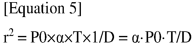
- From Equation 4, it is possible to know relations between light power of the germicidal light sources, sterilization time, intensity of the germicidal light required for sterilization, and travel distance of the germicidal light.
- In
Equations 1 to 5, I is an intensity (unit: mW/cm2) of the germicidal light incident per unit surface area of the sterilization target, P0 is a light power (unit: mW) of the germicidal light sources, T is an amount (unit: sec) of sterilization time, D is a dose (unit: mJ/cm2) of the germicidal light delivered per unit surface area of the sterilization target, r is a distance (unit: cm) to the sterilization target (travel distance), and α is an experimental constant. Here, the experimental constant is a value determined through experiments on relations between the light power (P0) of the germicidal light sources and the intensity (I) of the germicidal light incident on the surface of the sterilization target. - The
calculation unit 730 may calculate various types of information necessary for sterilization based on information calculated according toEquations 1 to 5. - In this embodiment, the
calculation unit 730 may calculate an intensity of the germicidal light required to sufficiently sterilize a space to be sterilized based on the information about the distance to the sterilization target, which is received from thesecond sensor 722. - The
calculation unit 730 may transmit a sterilization intensity signal containing information about the calculated intensity of the germicidal light to thecontroller 750. - In addition, the
calculation unit 730 may transmit the sterilization time signal received from theinput unit 710 to thetimer 740. - The
timer 740 may receive the sterilization time signal from theinput unit 710 or thecalculation unit 730. - In addition, the
timer 740 may transmit a second sterilization start signal and a second sterilization termination signal to thecontroller 750 based on the received sterilization time signal. - The
controller 750 may receive the sterilization intensity signal from thecalculation unit 730 and may receive the second sterilization start signal and the second sterilization termination signal from thetimer 740. - The
controller 750 may control the amount of current supplied to thesterilization unit 760 based on the sterilization intensity signal received from thecalculation unit 730. That is, thecontroller 750 may control the intensity of the germicidal light emitted from thesterilization unit 760 through control over the amount of current supplied to thesterilization unit 760. - In addition, the
controller 750 may initiate power supply to thesterilization unit 760 in response to the second sterilization start signal from thetimer 740. Further, thecontroller 750 may shut off power supply to thesterilization unit 760 in response to the second sterilization termination signal from thetimer 740. - In this way, the sterilizing
device 700 according to this embodiment can automatically adjust the intensity of the germicidal light based on the measured distance to the sterilization target to complete sterilization in the input sterilization time. - Although the present disclosure has been described with reference to an example in which sterilization time is set via the
input unit 710, it will be understood that settings input via theinput unit 710 is not limited thereto. - In another embodiment, intensity of the germicidal light may be set via the
input unit 710. In this embodiment, thecalculation unit 730 may calculate sterilization time based on the intensity of the germicidal light set via theinput unit 710. - The
calculation unit 730 may transmit a sterilization time signal containing information about the calculated sterilization time to thetimer 740. - The
timer 740 may transmit the second sterilization start signal and the second sterilization termination signal to thecontroller 750 based on the sterilization time signal received from thecalculation unit 730. - The
controller 750 may initiate or shut off power supply to thesterilization unit 760 in response to the second sterilization start signal or the second sterilization termination signal received from thetimer 740. That is, thecontroller 750 may control the time thesterilization unit 760 starts or stops operation in response to the second sterilization start signal or the second sterilization termination signal. - In addition, the
controller 750 may receive information about the intensity of the germicidal light from theinput unit 710 or thecalculation unit 730. Accordingly, thecontroller 750 may control operation of thesterilization unit 760 in response to the signals from thetimer 740 while controlling the intensity of the germicidal light through control over the amount of current supplied to thesterilization unit 760. - In a further embodiment, the sterilizing
device 700 may automatically calculate sterilization time and may perform sterilization for the calculated sterilization time. - The
calculation unit 730 may calculate sterilization time based on the information about the distance to the sterilization target, which is received from thesecond sensor 722. - That is, without user input of sterilization time via the
input unit 710, thecalculation unit 730 can calculate sterilization time required for sterilization based on the distance to the sterilization target and the preset basic intensity of the germicidal light. Thecalculation unit 730 may generate a sterilization time signal and may transmit the generated sterilization time signal to thetimer 740. - In this way, the sterilizing
device 700 according to this embodiment of the present disclosure can perform efficient sterilization through automatic calculation of sterilization time, sterilization intensity, sterilization range, and the like, based on input information. - Although the present disclosure has been described with reference to some embodiments in conjunction with the accompanying drawings, it should be understood that these embodiments are provided for illustration only and are not to be construed in any way as limiting the present disclosure. The scope of the present disclosure should be defined by the appended claims and equivalents thereto.
Claims (20)
- A sterilizing module comprising:a support member; and multiple germicidal light sources mounted on the support member and emitting germicidal light, the germicidal light being light having a wavelength capable of inactivating microorganisms,wherein respective light exit surfaces of the multiple germicidal light sources face in different directions from one another, andthe sterilizing module illuminates a sterilization target with the germicidal light at an irradiance greater than a minimum irradiance required for sterilization.
- The sterilizing module according to claim 1, wherein:
the sterilization unit comprises a first sterilization unit and a second sterilization unit each comprising the support member and the multiple germicidal light sources, the first sterilization unit and the second sterilization unit facing in different directions from one another. - The sterilizing module according to claim 2, wherein:
the sterilization unit comprises a pair of first sterilization units spaced apart from each other and facing in opposite directions and a pair of second sterilization units spaced apart from each other and facing in opposite directions, the pair of second sterilization units being disposed between the pair of first sterilization units. - The sterilizing module according to claim 2, wherein the sterilization unit further comprises a third sterilization unit comprising the germicidal light sources, the third sterilization unit being disposed between the first sterilization unit and the second sterilization unit.
- The sterilizing module according to claim 2, wherein the sterilization unit further comprises a third sterilization unit comprising the germicidal light sources, the third sterilization unit being disposed above or below the first sterilization unit or the second sterilization unit.
- The sterilizing module according to claim 1, wherein respective light exit surfaces of two germicidal light sources disposed at opposite ends of the support member, among the multiple germicidal light sources, face in opposite directions with respect to a central axis of the support member.
- The sterilizing module according to claim 1, wherein the sterilization unit further comprises multiple securing members each having a mounting surface on which the germicidal light source is mounted, respective mounting surfaces of the multiple securing members facing in different directions from one another.
- The sterilizing module according to claim 1, wherein the sterilizing module has an illumination uniformity of 75% or more.
- A sterilizing device comprising:a main frame;a sterilization unit comprising multiple germicidal light sources emitting germicidal light, the germicidal light being light having a wavelength capable of inactivating microorganisms; andmultiple connection members connecting the main frame to the sterilization unit,wherein the sterilization unit comprises a first sterilization unit and a second sterilization unit each comprising a support member and the multiple germicidal light sources,the multiple germicidal light sources are disposed on the support member with respective light exit surfaces thereof facing in different directions from one another, andthe sterilizing device illuminates a sterilization target with the germicidal light at an irradiance greater than a minimum irradiance required for sterilization.
- The sterilizing device according to claim 9, wherein the first sterilization unit and the second sterilization unit face in different directions from one another.
- The sterilizing device according to claim 10, wherein the sterilization unit comprises a pair of first sterilization units spaced apart from each other and facing in opposite directions and a pair of second sterilization units spaced apart from each other and facing in opposite directions, the pair of second sterilization units being disposed between the pair of first sterilization units.
- The sterilizing device according to claim 10, wherein the sterilization unit further comprises a third sterilization unit comprising the germicidal light sources and mounted on the connection member or the main frame, the third sterilization unit being disposed between the first sterilization unit and the second sterilization unit.
- The sterilizing device according to claim 10, wherein the sterilization unit further comprises a third sterilization unit comprising the germicidal light sources and mounted on the connection member or the main frame, the third sterilization unit being disposed above or below the first sterilization unit or the second sterilization unit.
- The sterilizing device according to claim 9, wherein respective light exit surfaces of two germicidal light sources disposed at opposite ends of the support member, among the multiple germicidal light sources, face in opposite directions with respect to a central axis of the support member.
- The sterilizing device according to claim 9, wherein the sterilization unit further comprises multiple securing members each having a mounting surface on which the germicidal light source is mounted and a securing portion secured to the support member, respective mounting surfaces of the multiple securing members facing in different directions from one another.
- The sterilizing device according to claim 9, further comprising:
an object detection sensor detecting movement of an object. - The sterilizing device according to claim 16, further comprising:
a controller controlling the sterilization unit to stop emission of the germicidal light upon detection of an object by the object detection sensor. - The sterilizing device according to claim 16, further comprising:
at least one of a distance sensor measuring a distance to a sterilization target and a timer transmitting a signal for controlling sterilization time to the controller. - The sterilizing device according to claim 18, further comprising:
a calculation unit calculating at least one of intensity of the germicidal light and sterilization time based on at least one of information about the distance to the sterilization target and information about the sterilization time. - The sterilizing device according to claim 9, wherein the sterilizing device has an illumination uniformity of 75% or more.
Applications Claiming Priority (4)
| Application Number | Priority Date | Filing Date | Title |
|---|---|---|---|
| US202063033386P | 2020-06-02 | 2020-06-02 | |
| US202063064491P | 2020-08-12 | 2020-08-12 | |
| US17/335,785 US12070524B2 (en) | 2020-06-02 | 2021-06-01 | Sterilization unit and sterilization apparatus including the same |
| PCT/KR2021/006867 WO2021246775A1 (en) | 2020-06-02 | 2021-06-02 | Sterilizing module, and sterilizing device comprising sterilizing module |
Publications (2)
| Publication Number | Publication Date |
|---|---|
| EP4144380A1 true EP4144380A1 (en) | 2023-03-08 |
| EP4144380A4 EP4144380A4 (en) | 2024-05-22 |
Family
ID=78706537
Family Applications (1)
| Application Number | Title | Priority Date | Filing Date |
|---|---|---|---|
| EP21817798.8A Pending EP4144380A4 (en) | 2020-06-02 | 2021-06-02 | Sterilizing module, and sterilizing device comprising sterilizing module |
Country Status (4)
| Country | Link |
|---|---|
| US (2) | US12070524B2 (en) |
| EP (1) | EP4144380A4 (en) |
| CN (1) | CN115884797A (en) |
| WO (1) | WO2021246775A1 (en) |
Families Citing this family (2)
| Publication number | Priority date | Publication date | Assignee | Title |
|---|---|---|---|---|
| US11964062B2 (en) | 2019-09-03 | 2024-04-23 | Luxhygenix Inc. | Antimicrobial device using ultraviolet light |
| US12070524B2 (en) | 2020-06-02 | 2024-08-27 | Seoul Viosys Co., Ltd. | Sterilization unit and sterilization apparatus including the same |
Family Cites Families (13)
| Publication number | Priority date | Publication date | Assignee | Title |
|---|---|---|---|---|
| JPH0663107A (en) | 1992-08-25 | 1994-03-08 | Sani Clean Nagano:Kk | Device for sterilizing and disinfecting the whole room of variable ultraviolet irradiation direction type |
| DE102012211888B4 (en) | 2012-07-06 | 2014-04-24 | Wobben Properties Gmbh | Apparatus for producing reinforcing baskets for tower segments, in particular for tower segments of wind energy installations |
| KR101302400B1 (en) | 2012-09-10 | 2013-09-02 | (주)썬웨이브 | Led module for sterilizing and dring, and apparatus having the same |
| CN103721289A (en) * | 2012-10-12 | 2014-04-16 | 易志翰 | Ultraviolet sterilizing device |
| AU2013361188B2 (en) | 2012-12-19 | 2017-05-11 | Leviant, Inc. | Sterilization units, systems, and methods |
| KR101900029B1 (en) | 2015-07-02 | 2018-09-18 | 제넥스 디스인펙션 서비시즈, 엘엘씨 | A sterilizing device having a configuration for selectively performing different disinfecting modes inside and outside of the sterilizing device |
| KR101724481B1 (en) | 2015-11-13 | 2017-04-11 | 주식회사 파나시아 | UV Sanitizing System |
| KR101742489B1 (en) | 2016-02-11 | 2017-06-02 | 전자부품연구원 | Mobile robot apparatus and system for UV disinfection |
| US10517975B2 (en) | 2017-01-12 | 2019-12-31 | Industrial Technology Research Institute | Light source apparatus and method of using the same |
| CN207137065U (en) * | 2017-02-21 | 2018-03-27 | 绍兴市大舜农业发展有限公司 | A kind of ultraviolet germicidal lamp for fresh-keeping ice house |
| WO2018164845A1 (en) | 2017-03-10 | 2018-09-13 | Arthur Kreitenberg | Operator shielded manually transportable ultraviolet disinfection |
| CN112135644B (en) * | 2018-01-16 | 2022-07-22 | 紫阳股份有限公司 | Adaptive multi-vector illumination delivery system |
| US12070524B2 (en) | 2020-06-02 | 2024-08-27 | Seoul Viosys Co., Ltd. | Sterilization unit and sterilization apparatus including the same |
-
2021
- 2021-06-01 US US17/335,785 patent/US12070524B2/en active Active
- 2021-06-02 WO PCT/KR2021/006867 patent/WO2021246775A1/en not_active Ceased
- 2021-06-02 EP EP21817798.8A patent/EP4144380A4/en active Pending
- 2021-06-02 CN CN202180040114.7A patent/CN115884797A/en active Pending
-
2024
- 2024-06-11 US US18/739,605 patent/US12343441B2/en active Active
Also Published As
| Publication number | Publication date |
|---|---|
| US12070524B2 (en) | 2024-08-27 |
| US20240325579A1 (en) | 2024-10-03 |
| WO2021246775A1 (en) | 2021-12-09 |
| US12343441B2 (en) | 2025-07-01 |
| EP4144380A4 (en) | 2024-05-22 |
| CN115884797A (en) | 2023-03-31 |
| US20210369894A1 (en) | 2021-12-02 |
Similar Documents
| Publication | Publication Date | Title |
|---|---|---|
| US12343441B2 (en) | Sterilization unit and sterilization apparatus including the same | |
| US11364313B2 (en) | Fixed position hybrid germicidal irradiation apparatus, method, and system | |
| US11219700B2 (en) | Hard surface disinfection system and method | |
| US10556025B2 (en) | Fixed position hybrid germicidal irradiation apparatus, method, and system | |
| US12465784B2 (en) | Irradiation module and device and method for irradiation with medical and cosmetic radiation | |
| US12029825B2 (en) | Fixed position hybrid germicidal irradiation apparatus, method, and system | |
| US20200171321A1 (en) | Light irradiation device for synthesis of functional substance in a human body | |
| US20260027383A1 (en) | Adaptive photobiomodulation (pbm) | |
| US11058596B2 (en) | Autoregulation of irradiance in phototherapy systems | |
| KR20190015963A (en) | sterilization device | |
| KR20180131247A (en) | Sterilization device | |
| KR20210143094A (en) | Elevator button sterilization device using ultraviolet light | |
| KR20220037933A (en) | Fungal infections treating device | |
| US20210330835A1 (en) | Ultraviolet radiation disinfection system and method | |
| KR20220014725A (en) | Sterilizing device | |
| US12508335B2 (en) | Light emitting system for disinfecting a target area | |
| US20220008747A1 (en) | Phototherapy apparatus | |
| KR102845442B1 (en) | sterilization device | |
| ES2602230T3 (en) | Cooking Field Device | |
| EP4472680B1 (en) | Uv-b light generating system | |
| US20240293591A1 (en) | Ultraviolet disinfecting apparatus | |
| KR20220113900A (en) | Fungal infections treating device | |
| CN120132233A (en) | A power adjustable short-wave ultraviolet uniform light emitting device |
Legal Events
| Date | Code | Title | Description |
|---|---|---|---|
| STAA | Information on the status of an ep patent application or granted ep patent |
Free format text: STATUS: THE INTERNATIONAL PUBLICATION HAS BEEN MADE |
|
| PUAI | Public reference made under article 153(3) epc to a published international application that has entered the european phase |
Free format text: ORIGINAL CODE: 0009012 |
|
| STAA | Information on the status of an ep patent application or granted ep patent |
Free format text: STATUS: REQUEST FOR EXAMINATION WAS MADE |
|
| 17P | Request for examination filed |
Effective date: 20221201 |
|
| AK | Designated contracting states |
Kind code of ref document: A1 Designated state(s): AL AT BE BG CH CY CZ DE DK EE ES FI FR GB GR HR HU IE IS IT LI LT LU LV MC MK MT NL NO PL PT RO RS SE SI SK SM TR |
|
| DAV | Request for validation of the european patent (deleted) | ||
| DAX | Request for extension of the european patent (deleted) | ||
| A4 | Supplementary search report drawn up and despatched |
Effective date: 20240419 |
|
| RIC1 | Information provided on ipc code assigned before grant |
Ipc: A61L 9/20 20060101ALI20240415BHEP Ipc: A61L 9/18 20060101ALI20240415BHEP Ipc: A61L 2/10 20060101ALI20240415BHEP Ipc: A61L 2/24 20060101ALI20240415BHEP Ipc: A61L 2/08 20060101AFI20240415BHEP |
|
| STAA | Information on the status of an ep patent application or granted ep patent |
Free format text: STATUS: EXAMINATION IS IN PROGRESS |
|
| 17Q | First examination report despatched |
Effective date: 20250603 |