EP4144313A1 - Spinal fastener with serrated thread - Google Patents
Spinal fastener with serrated thread Download PDFInfo
- Publication number
- EP4144313A1 EP4144313A1 EP22203966.1A EP22203966A EP4144313A1 EP 4144313 A1 EP4144313 A1 EP 4144313A1 EP 22203966 A EP22203966 A EP 22203966A EP 4144313 A1 EP4144313 A1 EP 4144313A1
- Authority
- EP
- European Patent Office
- Prior art keywords
- thread
- shaft
- fastener
- length
- fasteners
- Prior art date
- Legal status (The legal status is an assumption and is not a legal conclusion. Google has not performed a legal analysis and makes no representation as to the accuracy of the status listed.)
- Granted
Links
Images









Classifications
-
- A—HUMAN NECESSITIES
- A61—MEDICAL OR VETERINARY SCIENCE; HYGIENE
- A61B—DIAGNOSIS; SURGERY; IDENTIFICATION
- A61B17/00—Surgical instruments, devices or methods
- A61B17/56—Surgical instruments or methods for treatment of bones or joints; Devices specially adapted therefor
- A61B17/58—Surgical instruments or methods for treatment of bones or joints; Devices specially adapted therefor for osteosynthesis, e.g. bone plates, screws or setting implements
- A61B17/68—Internal fixation devices, including fasteners and spinal fixators, even if a part thereof projects from the skin
- A61B17/84—Fasteners therefor or fasteners being internal fixation devices
- A61B17/86—Pins or screws or threaded wires; nuts therefor
-
- A—HUMAN NECESSITIES
- A61—MEDICAL OR VETERINARY SCIENCE; HYGIENE
- A61B—DIAGNOSIS; SURGERY; IDENTIFICATION
- A61B17/00—Surgical instruments, devices or methods
- A61B17/56—Surgical instruments or methods for treatment of bones or joints; Devices specially adapted therefor
- A61B17/58—Surgical instruments or methods for treatment of bones or joints; Devices specially adapted therefor for osteosynthesis, e.g. bone plates, screws or setting implements
- A61B17/68—Internal fixation devices, including fasteners and spinal fixators, even if a part thereof projects from the skin
- A61B17/70—Spinal positioners or stabilisers, e.g. stabilisers comprising fluid filler in an implant
- A61B17/7001—Screws or hooks combined with longitudinal elements which do not contact vertebrae
- A61B17/7032—Screws or hooks with U-shaped head or back through which longitudinal rods pass
-
- A—HUMAN NECESSITIES
- A61—MEDICAL OR VETERINARY SCIENCE; HYGIENE
- A61B—DIAGNOSIS; SURGERY; IDENTIFICATION
- A61B17/00—Surgical instruments, devices or methods
- A61B17/56—Surgical instruments or methods for treatment of bones or joints; Devices specially adapted therefor
- A61B17/58—Surgical instruments or methods for treatment of bones or joints; Devices specially adapted therefor for osteosynthesis, e.g. bone plates, screws or setting implements
- A61B17/68—Internal fixation devices, including fasteners and spinal fixators, even if a part thereof projects from the skin
- A61B17/70—Spinal positioners or stabilisers, e.g. stabilisers comprising fluid filler in an implant
- A61B17/7001—Screws or hooks combined with longitudinal elements which do not contact vertebrae
- A61B17/7035—Screws or hooks, wherein a rod-clamping part and a bone-anchoring part can pivot relative to each other
- A61B17/7037—Screws or hooks, wherein a rod-clamping part and a bone-anchoring part can pivot relative to each other wherein pivoting is blocked when the rod is clamped
-
- A—HUMAN NECESSITIES
- A61—MEDICAL OR VETERINARY SCIENCE; HYGIENE
- A61B—DIAGNOSIS; SURGERY; IDENTIFICATION
- A61B17/00—Surgical instruments, devices or methods
- A61B17/56—Surgical instruments or methods for treatment of bones or joints; Devices specially adapted therefor
- A61B17/58—Surgical instruments or methods for treatment of bones or joints; Devices specially adapted therefor for osteosynthesis, e.g. bone plates, screws or setting implements
- A61B17/68—Internal fixation devices, including fasteners and spinal fixators, even if a part thereof projects from the skin
- A61B17/84—Fasteners therefor or fasteners being internal fixation devices
- A61B17/86—Pins or screws or threaded wires; nuts therefor
- A61B17/8605—Heads, i.e. proximal ends projecting from bone
-
- A—HUMAN NECESSITIES
- A61—MEDICAL OR VETERINARY SCIENCE; HYGIENE
- A61B—DIAGNOSIS; SURGERY; IDENTIFICATION
- A61B17/00—Surgical instruments, devices or methods
- A61B17/56—Surgical instruments or methods for treatment of bones or joints; Devices specially adapted therefor
- A61B17/58—Surgical instruments or methods for treatment of bones or joints; Devices specially adapted therefor for osteosynthesis, e.g. bone plates, screws or setting implements
- A61B17/68—Internal fixation devices, including fasteners and spinal fixators, even if a part thereof projects from the skin
- A61B17/84—Fasteners therefor or fasteners being internal fixation devices
- A61B17/86—Pins or screws or threaded wires; nuts therefor
- A61B17/8605—Heads, i.e. proximal ends projecting from bone
- A61B17/861—Heads, i.e. proximal ends projecting from bone specially shaped for gripping driver
- A61B17/862—Heads, i.e. proximal ends projecting from bone specially shaped for gripping driver at the periphery of the screw head
-
- A—HUMAN NECESSITIES
- A61—MEDICAL OR VETERINARY SCIENCE; HYGIENE
- A61B—DIAGNOSIS; SURGERY; IDENTIFICATION
- A61B17/00—Surgical instruments, devices or methods
- A61B17/56—Surgical instruments or methods for treatment of bones or joints; Devices specially adapted therefor
- A61B17/58—Surgical instruments or methods for treatment of bones or joints; Devices specially adapted therefor for osteosynthesis, e.g. bone plates, screws or setting implements
- A61B17/68—Internal fixation devices, including fasteners and spinal fixators, even if a part thereof projects from the skin
- A61B17/84—Fasteners therefor or fasteners being internal fixation devices
- A61B17/86—Pins or screws or threaded wires; nuts therefor
- A61B17/8625—Shanks, i.e. parts contacting bone tissue
-
- A—HUMAN NECESSITIES
- A61—MEDICAL OR VETERINARY SCIENCE; HYGIENE
- A61B—DIAGNOSIS; SURGERY; IDENTIFICATION
- A61B17/00—Surgical instruments, devices or methods
- A61B17/56—Surgical instruments or methods for treatment of bones or joints; Devices specially adapted therefor
- A61B17/58—Surgical instruments or methods for treatment of bones or joints; Devices specially adapted therefor for osteosynthesis, e.g. bone plates, screws or setting implements
- A61B17/68—Internal fixation devices, including fasteners and spinal fixators, even if a part thereof projects from the skin
- A61B17/84—Fasteners therefor or fasteners being internal fixation devices
- A61B17/86—Pins or screws or threaded wires; nuts therefor
- A61B17/8625—Shanks, i.e. parts contacting bone tissue
- A61B17/863—Shanks, i.e. parts contacting bone tissue with thread interrupted or changing its form along shank, other than constant taper
-
- A—HUMAN NECESSITIES
- A61—MEDICAL OR VETERINARY SCIENCE; HYGIENE
- A61B—DIAGNOSIS; SURGERY; IDENTIFICATION
- A61B17/00—Surgical instruments, devices or methods
- A61B17/56—Surgical instruments or methods for treatment of bones or joints; Devices specially adapted therefor
- A61B17/58—Surgical instruments or methods for treatment of bones or joints; Devices specially adapted therefor for osteosynthesis, e.g. bone plates, screws or setting implements
- A61B17/68—Internal fixation devices, including fasteners and spinal fixators, even if a part thereof projects from the skin
- A61B17/84—Fasteners therefor or fasteners being internal fixation devices
- A61B17/86—Pins or screws or threaded wires; nuts therefor
- A61B17/8625—Shanks, i.e. parts contacting bone tissue
- A61B17/8635—Tips of screws
-
- A—HUMAN NECESSITIES
- A61—MEDICAL OR VETERINARY SCIENCE; HYGIENE
- A61B—DIAGNOSIS; SURGERY; IDENTIFICATION
- A61B17/00—Surgical instruments, devices or methods
- A61B17/56—Surgical instruments or methods for treatment of bones or joints; Devices specially adapted therefor
- A61B17/58—Surgical instruments or methods for treatment of bones or joints; Devices specially adapted therefor for osteosynthesis, e.g. bone plates, screws or setting implements
- A61B17/68—Internal fixation devices, including fasteners and spinal fixators, even if a part thereof projects from the skin
- A61B17/84—Fasteners therefor or fasteners being internal fixation devices
- A61B17/86—Pins or screws or threaded wires; nuts therefor
- A61B17/864—Pins or screws or threaded wires; nuts therefor hollow, e.g. with socket or cannulated
-
- A—HUMAN NECESSITIES
- A61—MEDICAL OR VETERINARY SCIENCE; HYGIENE
- A61B—DIAGNOSIS; SURGERY; IDENTIFICATION
- A61B17/00—Surgical instruments, devices or methods
- A61B17/56—Surgical instruments or methods for treatment of bones or joints; Devices specially adapted therefor
- A61B17/58—Surgical instruments or methods for treatment of bones or joints; Devices specially adapted therefor for osteosynthesis, e.g. bone plates, screws or setting implements
- A61B17/68—Internal fixation devices, including fasteners and spinal fixators, even if a part thereof projects from the skin
- A61B17/84—Fasteners therefor or fasteners being internal fixation devices
- A61B17/86—Pins or screws or threaded wires; nuts therefor
- A61B2017/8655—Pins or screws or threaded wires; nuts therefor with special features for locking in the bone
Definitions
- the present invention generally relates to spinal fixation devices, and more particularly to spinal fasteners having serrated threads.
- spinal fixation A technique commonly referred to as spinal fixation is employed for fusing together and/or mechanically immobilizing vertebrae of the spine.
- Spinal fixation may also be used to alter the alignment of adjacent vertebrae relative to one another so as to change the overall alignment of the spine.
- Such techniques have been used effectively to treat many degenerative conditions and, in most cases, to relieve pain suffered by the patient.
- a surgeon will install pedicle screws into the pedicles of adjacent vertebrae (along one or multiple levels of the spine) and thereafter connect the screws with a spinal rod in order to provide immobilization and stabilization of the vertebral column.
- pedicle screws connected by fixation rods is an important treatment method employed by spinal surgeons.
- surgeon fatigue and bone fracturing can be significant problems during surgery. Surgeon fatigue can adversely affect the accuracy of the insertion process and the depth to which the screws are inserted within the pedicle bone.
- a fastener configured for spinal applications as defined in claim 1 and in the corresponding depending claims.
- a corresponding kit as defined in the appended claims.
- a first aspect of the present disclosure is a fastener having a head including a channel adapted to receive a spinal rod and a shaft extending from the head to a distal tip and including a thread, at least a portion of the thread being serrated.
- the shaft has a longitudinal axis and an angle between the longitudinal axis and thread may vary along a length of the shaft.
- the serrated portion of the thread may include serrations having a width that increases along a portion of a length of the thread toward the distal tip.
- the shaft may be cannulated.
- the head may be polyaxially movable with respect to the shaft.
- the shaft may be tapered. Further, the taper of the shaft measured by a line over a surface of the thread at points on two or more revolutions of the thread may be between 16 and 20 degrees relative to the longitudinal axis of the shaft.
- the serrated portion of the thread may include serrations having a width that decreases over a part of the serrated portion toward the distal tip.
- the thread may include walls disposed between the shaft and a surface of the serrations, the walls angled so that walls adjacent to one another along the longitudinal axis are at a 55 to 65 degree angle with respect to each other.
- the head may be monoaxially attached to the shaft.
- a second aspect of the disclosure is a fastener having a head including a channel adapted to receive a spinal rod, a shaft coupled with the head, the shaft including a distal tip, a thread extending between the head and the distal tip, and a serration extending along at least a portion of the thread, the serration including peaks and troughs.
- the peaks are disposed at a radial distance to the longitudinal axis of the shaft greater than a radial distance to the longitudinal axis of the shaft from the troughs adjacent to the peak, the teeth may have a width measured parallel to the troughs such that the width may be greater at the troughs than at the peaks.
- the peaks of the teeth may include a first type defined by an edge at an abutment between surfaces connecting the peak with adjacent troughs and a second type defined by a planar surface.
- the serration may include a progressively increasing pitch from the tip toward the head.
- the first peak may vary in height along a length of the thread so that a first short peak with a first radius measured from the longitudinal axis of the shaft may be adjacent to a first tall peak with a second radius, which in turn may be adjacent to a second short peak with a third radius, adjacent to a second tall peak with a fourth radius, the first and third radii may be similar and may both be lesser in dimension than the second and fourth radii.
- the peaks may extend along helical curves winding around the shaft in a direction opposite to a helical curve along which the thread extends.
- the peaks may extend along axes that are parallel to or aligned with a longitudinal axis of the shaft.
- the shaft may include a cutting flute that extends in a linear direction along an axis angled with respect to a longitudinal axis of the shaft.
- the shaft may include a cutting flute that extends along a helical path from the distal tip of the shaft.
- a third aspect of the fastener is a fastener having a head including a channel adapted to receive a spinal rod, a shaft coupled to the head, the shaft including a distal tip, a thread extending between the head and the distal tip, and a serration extending along approximately 35 percent of a length of the thread.
- the serration may include peaks and troughs.
- the distal tip may taper such that an angle between an axis measured from a first point on a surface of the thread at a first end of the taper to a second point at the tip of the fastener on the longitudinal axis of the shaft may be approximately 20 to 30 degrees relative to the longitudinal axis of the shaft.
- the present invention relates to a fastener to be used in conjunction with spinal rods during spinal surgery.
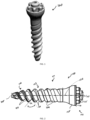
- Figs. 1-6 depict a first embodiment of a fastener 100 that is configured for spinal applications, and in particular, for use as a pedicle screw or fastener.
- Fastener 100 includes a screw body 101 and a tulip, which has a channel adapted to receive a spinal rod.
- a spinal rod can be installed into the tulip and held in place by a set screw (not shown), which is threaded into internal threads of the tulip. While the tulip is not shown in Figs. 1-6 , tulips are featured in the embodiments shown in Figs. 10-13 , described below.
- Fastener 100 is poly-axial in that screw body 101 is separate from the tulip.
- the tulip and proximal end of the screw body can generally be referred to as a head of fastener 100.
- Screw body 101 includes a shaft 103 that extends along a longitudinal axis 108 from a proximal portion 102 or a head of fastener 100 to a distal tip 105.
- the tulip is polyaxially movable ( i.e., a polyaxial pedicle screw) with respect to proximal portion 102 of screw body 101.
- Proximal end 102 of screw body 101 forms an interference fit connection with a distal opening of the tulip to create the poly-axial connection.
- the tulip can swivel about and form different angles with screw body 101 to facilitate proper rod placement.
- the fastener can be a monolithic structure (i.e., a monoaxial pedicle screw) having the tulip statically connected with the proximal end of the screw body. Both of such embodiments may additionally have retractor blades extending from the tulip, such as those described below in connection with Fig. 12 .
- Shaft 103 includes a thread 104 extending between proximal portion 102 and distal tip 105. Beginning thread 104 at distal tip 105 allows shaft 103 to engage and anchor into the bone immediately upon contact.
- thread 104 includes along a length thereof a serrated portion 106 that has individual serrations 107.
- Serrated portion 106 extends along about 35 to 40 percent of a length of thread 104. In certain embodiments, serrated portion 106 extends along 35 percent of the length of thread 104. In other embodiments, the range of serrated portion 106 can be about 25-45 percent of a length of thread 104, about 20-50 percent of a length of thread 104, or about 10-60 percent of a length of thread 104.
- This ratio of the serrated portion to the overall thread length allows for a consistent feel during manual insertion, regardless of the screw length.
- the inclusion of serrated portion 106 provides a solution for the problems of the prior art, as described above.
- Serrations 107 reduce insertion torque, thereby improving ease of insertion, while not compromising pullout strength. Serrated screws also allow for a quicker insertion time. The reduced insertion torque reduces the chance of bone fracturing and breaching. Additionally, serrations 107 allow surgeons to retain tactile feedback with minimized energy exertion resulting in greater accuracy during positioning of fastener 100, as compared with manual screw insertion of other non-serrated prior art screws.
- Shaft 103 is tapered, such that the tapered portion of shaft 103 is defined by an angle of between 16 and 20 degrees measured between longitudinal axis 108 of the shaft 103 and an axis intersecting outer surfaces of thread 104 at two or more revolutions of thread 104.
- the tapered portion of shaft 103 extends along about 35 percent of the length of thread 104, which can match the length of thread 104 along which serrated portion 106 extends.
- the range of tapered portion can be about 25-45 percent of a length of thread 104, about 20-50 percent of a length of thread 104, or about 10-60 percent of a length of thread 104.
- This configuration is designed so that once a maximum diameter of the threads is reached, the serrated portion 106 ends so that the threads at the maximum diameter do not continue to cut into the bone. Further cutting into the bone by the maximum diameter threads can weaken the engagement between the later-inserted, non-serrated threads and the bone, which reduces tactile feedback to the user. Having the tapered portion of shaft 103 and serrated portion 106 both extend along the same amount of the length of thread 104 ( i.e., about 35 percent) allows some resistance at all times during insertion of the screw, which is desirable.
- Other embodiments in accordance with the present disclosure may include a shaft that is not tapered.
- proximal portion 102 of screw body 101 includes a proximally-facing flat top surface 126 and a distally-facing, generally spherical surface 125, which interfaces with the tulip to allow for polyaxial movement between the tulip and screw body 101.
- proximal portion 102 includes a projection 130 extending from a central portion of flat top surface 126.
- Proximal portion 102 further includes nubs 135 extending from flat top surface 126 at locations around the periphery thereof and surrounding projection 130. Nubs 135 are each smaller in size than projection 130.
- projections 130 and nubs 135 can vary depending on the corresponding tulip assembly and the corresponding insertion instruments, in the illustrated embodiment, projections 130 and nubs 135 are each rounded to have generally spherically-shaped proximal ends. As shown more clearly in Fig. 2 , in this embodiment, proximal portion 102 includes six nubs 135. The number of nubs 135 can vary in other embodiments.
- Thread 104 can have one or more of many cross-sectional areas, such as trapezoidal, square, triangular, rectangular or any other shape known in the art. As shown in Figs. 2 and 3 , thread 104 includes sidewalls 110 on either side that extend from an inner diameter of shaft 103 to an outer diameter of thread 104. Sidewalls 110 are angled such that sidewalls 110 that face one another along the longitudinal axis 108 of shaft 103 form an angle ⁇ therebetween of 60 degrees. Angle ⁇ can be about 60 degrees, as in the depicted embodiment, while it can range between about 55-65 degrees in other embodiments. In still other embodiments, angle ⁇ can range between about 45-75 degrees, and between about 40-80 degrees in other embodiments.
- Thread 104 is configured such that an angle between sidewall 110 and longitudinal axis 108 of shaft 103 varies along a length of the shaft 103. That is, the angle between the sidewall of thread 104 and longitudinal axis 108 varies along the path of thread 104. In other embodiments, the angle of sidewall 110 can be constant. In the embodiment shown in Figs. 1-6 , sidewalls 110 extend toward longitudinal axis 108 until they intersect with a concave, helical path between adjacent passes of thread 104, with the helical path containing the inner diameter of shaft 103. In other embodiments, sidewalls 110 may extend to the inner diameter of the shaft by intersecting or by the helical path between adjacent passes of thread 104 being flat instead of concave.
- thread 104 includes serrated portion 106 at a distal end of shaft 103 that continuously transitions into a smooth, non-serrated portion at a proximal end of shaft 103.
- Serrations 107 are geometrical cut-outs along serrated portion 106 that allow for easier insertion of fastener 100 into the pedicle bone by reducing the insertion torque. This reduction in torque limits surgeon fatigue and reduces the chance of fracturing or breaching of the pedicle bone.
- thread 104 has a tapered portion that defines a tapered angle ⁇ measured between longitudinal axis 108 of shaft 103 and an axis 120 intersecting distal tip 105 and an outer surface of thread 104 at a proximal end of the tapered portion of thread 104.
- Angle ⁇ is 25 degrees in the depicted embodiment. In other embodiments, angle ⁇ can be about 25 degrees, or between about 20 to 30 degrees. In still other embodiments, angle ⁇ can range between about 15-35 degrees, and between about 10-40 degrees in other embodiments.
- serrated portion 106 include peaks 112 and troughs 115 that alternate along serrated portion 106 to define serrations 107. Peaks 112 are triangular in shape looking along the longitudinal axis 108. Serrations 107 further include respective thicknesses 116 measured parallel to longitudinal axis 108 of shaft 103 such that successive thicknesses 116 increase in magnitude along a portion of a length of thread 104 toward distal tip 105. Each thickness 116 is measured from the distal end to the proximal end of each serration 107. In other embodiments, successive thicknesses can decrease in magnitude along a portion of a length of thread 104 toward distal tip 105 or can remain constant.
- each peak 112 is disposed at a radial distance from longitudinal axis 108 of shaft 103 that is greater than a radial distance from longitudinal axis 108 of shaft 103 to an adjacent trough 115.
- Each peak 112 has a thickness measured parallel to longitudinal axis 108 of shaft 103 that is less than a thickness measured parallel to longitudinal axis 108 of shaft 103 of an adjacent trough 115. In other words, due to the angle between sidewalls 110 of thread 104 and/or curvature of surfaces 117 of shaft 103, the thickness is greater at the troughs 115 than at the adjacent peaks 112.
- Serrations 107 include respective widths measured perpendicular to longitudinal axis 108 of shaft 103, such that successive widths decrease in magnitude along a portion of a length of thread 104 toward the distal tip 105. In other embodiments, successive widths can increase in magnitude along a portion of a length of thread 104 toward distal tip 105 or can remain constant.
- the pitch of a serration 107 is the distance between adjacent troughs 115 that define the serration 107, that is, from a first trough 115 across a peak 112 to an adjacent second trough 115.
- the pitch of the respective serrations 107 progressively and incrementally increases from distal tip 105 toward proximal portion 102 of shaft 103.
- the pitch of a serration 107 nearer the distal tip 105 is less than the pitch of a serration 107 closer to the proximal portion 102.
- the number of serrations 107 per revolution of thread 104 is constant, as shown in Fig.
- Fastener 200 is shown in Fig. 7 with serrations 207 running the entire length of thread 204 along shaft 203.
- Fastener 300 is shown in Fig. 8 having a cannulated shaft 303 that defines a passage 350 along the length of shaft 303. Passage 350 can extend along a full length of fastener 300 so that it is accessible at both the proximal and distal ends thereof, with the distal opening being shown in Fig. 7 .
- the proximal opening corresponds with the central projection at the proximal portion of fastener 300.
- Figs. 9A-9I each depict different embodiments having a varying number of serrations per each thread revolution.
- the pitch incrementally increases from the distal tip to the proximal portion.
- the pitch is smaller at the distal tip 405 than on threads 404 closer to the proximal portion 402 due to the tapered nature of the screw to allow for the same number of peaks per revolution of threads 404.
- Figs. 9A-9C depict fasteners having peaks of one type.
- peaks 612 are defined by a linear edge 613 at an abutment between surfaces connecting peak 612 with adjacent troughs.
- Figs. 9D-9I depict fasteners having peaks of two types.
- certain peaks are defined by a linear edge, while peaks 919 are defined by a flat or planar surface at an abutment between surfaces connecting peak 919 with adjacent troughs. 13.
- successive peaks along the serrated portion can alternate between the linear and planar peaks.
- the threads include two types of peaks that alternate and differ in height, which is the distance from the longitudinal axis of the screw body to the top of the peak.
- This configuration forms a double-V cut and can vary with a first tall peak, adjacent to a first short peak, the first short peak adjacent to a second tall peak, the pattern (tall-short-tall-short) continuing around the threads.
- the taller peaks can have the same or different height, though both are preferable greater in magnitude than the heights of the shorter peaks, which can be the same or different.
- the peaks and troughs are rounded.
- the threads are square shaped or rectangular in crosssection, having two linear edges defining each peak and two linear edges defining each trough.
- the serrations are scalloped such that the peaks are curved with the troughs forming linear edges.
- the serrations can be helical in the opposite direction of the threads of a fastener 1700. That is, serrations 1707 can have peaks 1712 that extend along helical curves winding around fastener 1700 in a direction opposite to the helical curve along which thread 1704 extends. In this way, peaks 1712 are not aligned with or parallel to a longitudinal axis X of shaft 1703.
- a fastener has a cutting flute that extends in a linear direction along an axis angled with respect to the longitudinal axis of the shaft.
- a fastener has a cutting flute that extends along a helical path from a distal tip of the shaft.
- Fasteners according to the present embodiments can include single or dual lead threads and can include one or more cutting flutes. A dual lead provides the fastener with superior pullout strength.
- Fig. 10 depicts an embodiment similar to fastener 100 in which a fastener 1100 is shown with a screw body 1101 and a tulip 1109.
- Fig. 11 depicts an embodiment similar to that of Fig. 10 , but one in which a fastener 2100 is not cannulated.
- An embodiment depicted in Fig. 12 is a fastener 3100 in which a tulip 3109 includes retractor blades 3111 that act as guides during insertion of a spinal rod and can be detached once the spinal rod is anchored to tulip 3109.
- Fig. 13 depicts an embodiment similar to fastener 100 in which a fastener 4100 has a longer shaft and a tulip 4109 is angled on its distal surface.
- Each screw has a diameter of 5.0 mm and a length of 35.0 mm, and is further configured as follows: Screw A Double Lead Non-Cannulated Cutting Flute No Serrations Screw B Double Lead Non-Cannulated Cutting Flute Serrations Screw C Double Lead Cannulated No Cutting Flute Serrations Screw D Double Lead Non-Cannulated No Cutting Flute Serrations
- Screws A-D were tested to determine mean maximum insertion torque. As shown in Fig. 14 , Screws B-D having serrations in accordance with the present disclosure showed superior performance to Screw A, which does not include serrations. The mean maximum insertion torque is less for all of Screws B-D as compared with Screw A. This evidences the desired result of lowering the insertion torque for a screw by providing serrations, to improve the performance of manual insertion.
- kits of screws in accordance with the present disclosure can include screws of different overall lengths having proportional serrated lengths based on a constant value.
- Kits of screws in accordance with the present disclosure can include screws of different lengths having serrated lengths according to these different "buckets" to provide multiple options for a user.
Landscapes
- Health & Medical Sciences (AREA)
- Orthopedic Medicine & Surgery (AREA)
- Life Sciences & Earth Sciences (AREA)
- Surgery (AREA)
- Neurology (AREA)
- Heart & Thoracic Surgery (AREA)
- Engineering & Computer Science (AREA)
- Biomedical Technology (AREA)
- Nuclear Medicine, Radiotherapy & Molecular Imaging (AREA)
- Medical Informatics (AREA)
- Molecular Biology (AREA)
- Animal Behavior & Ethology (AREA)
- General Health & Medical Sciences (AREA)
- Public Health (AREA)
- Veterinary Medicine (AREA)
- Surgical Instruments (AREA)
Abstract
Description
- The present application claims the benefit of the filing dates of
U.S. Provisional Patent Application No. 62/428,103 filed November 30, 2016 U.S. Non-Provisional Patent Application No. 15/645,264 filed July 10, 2017 - The present invention generally relates to spinal fixation devices, and more particularly to spinal fasteners having serrated threads.
- A technique commonly referred to as spinal fixation is employed for fusing together and/or mechanically immobilizing vertebrae of the spine. Spinal fixation may also be used to alter the alignment of adjacent vertebrae relative to one another so as to change the overall alignment of the spine. Such techniques have been used effectively to treat many degenerative conditions and, in most cases, to relieve pain suffered by the patient.
- In some applications, a surgeon will install pedicle screws into the pedicles of adjacent vertebrae (along one or multiple levels of the spine) and thereafter connect the screws with a spinal rod in order to provide immobilization and stabilization of the vertebral column. Whether conducted in conjunction with interbody fusion or across single or multiple levels of the spine, the use of pedicle screws connected by fixation rods is an important treatment method employed by spinal surgeons.
- Some surgeons insert pedicle screws via powered screw insertion, while other surgeons prefer manual screw insertion. For the surgeons that opt for manual screw insertion, surgeon fatigue and bone fracturing can be significant problems during surgery. Surgeon fatigue can adversely affect the accuracy of the insertion process and the depth to which the screws are inserted within the pedicle bone.
- There remains room for improvement in the design and use of pedicle screws, particularly in the case of manual insertion so that related surgical procedures can be performed with greater efficiency and consistency.
- According to the present invention, there is provided a fastener configured for spinal applications as defined in claim 1 and in the corresponding depending claims. There is also provided a corresponding kit as defined in the appended claims.
- A first aspect of the present disclosure is a fastener having a head including a channel adapted to receive a spinal rod and a shaft extending from the head to a distal tip and including a thread, at least a portion of the thread being serrated.
- In other embodiments according to the first aspect, the shaft has a longitudinal axis and an angle between the longitudinal axis and thread may vary along a length of the shaft. The serrated portion of the thread may include serrations having a width that increases along a portion of a length of the thread toward the distal tip. The shaft may be cannulated. The head may be polyaxially movable with respect to the shaft. The shaft may be tapered. Further, the taper of the shaft measured by a line over a surface of the thread at points on two or more revolutions of the thread may be between 16 and 20 degrees relative to the longitudinal axis of the shaft. The serrated portion of the thread may include serrations having a width that decreases over a part of the serrated portion toward the distal tip. The thread may include walls disposed between the shaft and a surface of the serrations, the walls angled so that walls adjacent to one another along the longitudinal axis are at a 55 to 65 degree angle with respect to each other. The head may be monoaxially attached to the shaft.
- A second aspect of the disclosure is a fastener having a head including a channel adapted to receive a spinal rod, a shaft coupled with the head, the shaft including a distal tip, a thread extending between the head and the distal tip, and a serration extending along at least a portion of the thread, the serration including peaks and troughs.
- In other embodiments according to the second aspect, the peaks are disposed at a radial distance to the longitudinal axis of the shaft greater than a radial distance to the longitudinal axis of the shaft from the troughs adjacent to the peak, the teeth may have a width measured parallel to the troughs such that the width may be greater at the troughs than at the peaks. The peaks of the teeth may include a first type defined by an edge at an abutment between surfaces connecting the peak with adjacent troughs and a second type defined by a planar surface. The serration may include a progressively increasing pitch from the tip toward the head. The first peak may vary in height along a length of the thread so that a first short peak with a first radius measured from the longitudinal axis of the shaft may be adjacent to a first tall peak with a second radius, which in turn may be adjacent to a second short peak with a third radius, adjacent to a second tall peak with a fourth radius, the first and third radii may be similar and may both be lesser in dimension than the second and fourth radii.
- The peaks may extend along helical curves winding around the shaft in a direction opposite to a helical curve along which the thread extends. The peaks may extend along axes that are parallel to or aligned with a longitudinal axis of the shaft. The shaft may include a cutting flute that extends in a linear direction along an axis angled with respect to a longitudinal axis of the shaft. The shaft may include a cutting flute that extends along a helical path from the distal tip of the shaft.
- Other embodiments according to the second aspect, taken alon or in combination, are the following:
- each peak is disposed at a radial distance from a longitudinal axis of the shaft that is greater than a radial distance from the longitudinal axis of the shaft to an adjacent trough, each peak having a thickness measured parallel to the longitudinal axis of the shaft that is less than a thickness measured parallel to the longitudinal axis of the shaft of an adjacent trough;
- the peaks include a first type of peak defined by a linear edge at an abutment between surfaces connecting the peak with adjacent troughs and a second type of peak different from the first type of peak and defined by a planar surface at an abutment between surfaces connecting the peak with adjacent troughs;
- successive peaks along the serrated portion alternate between the first type of peak and the second type of peak;
- the first type of peak varies in height along a length of the serrated portion and includes a first short peak with a first radius measured from the longitudinal axis of the shaft adjacent to a first tall peak with a second radius, which in turn is adjacent to a second short peak with a third radius, adjacent to a second tall peak with a fourth radius, the first and third radii being similar and both lesser in dimension than the second and fourth radii;
- the serrated portion includes a progressively increasing pitch from the tip toward the head;
- the peaks extend along helical curves winding around the shaft in a direction opposite to a helical curve along which the thread extends;
- the peaks extend along axes that are parallel to or aligned with a longitudinal axis of the shaft;
- the shaft includes a cutting flute that extends in a linear direction along an axis angled with respect to a longitudinal axis of the shaft;
- the shaft includes a cutting flute that extends along a helical path from the distal tip of the shaft.
- A third aspect of the fastener is a fastener having a head including a channel adapted to receive a spinal rod, a shaft coupled to the head, the shaft including a distal tip, a thread extending between the head and the distal tip, and a serration extending along approximately 35 percent of a length of the thread.
- In other embodiments according to the third aspect, the serration may include peaks and troughs. The distal tip may taper such that an angle between an axis measured from a first point on a surface of the thread at a first end of the taper to a second point at the tip of the fastener on the longitudinal axis of the shaft may be approximately 20 to 30 degrees relative to the longitudinal axis of the shaft.
-
-
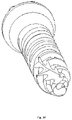
Fig. 1 is a perspective view of a fastener in accordance with a first embodiment of the present disclosure. -
Fig. 2 is a front plan view of the fastener ofFig. 1 . -
Fig. 3 is an enlarged front plan view of a distal portion of the fastener ofFig. 1 . -
Fig. 4 is a top plan view of the fastener ofFig. 1 . -
Fig. 5 is a bottom plan view of the fastener ofFig. 1 . -
Fig. 6 is an enlarged bottom plan view of a portion of the fastener ofFig. 1 . -
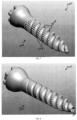
Fig. 7 is a perspective view of a fastener in accordance with another embodiment of the present invention. -
Fig. 8 is a perspective view of a fastener in accordance with another embodiment of the present disclosure. -
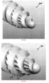
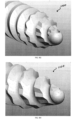
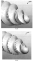
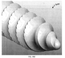
Figs. 9A-9Q are perspective views of distal portions of other embodiments of fasteners in accordance with the present disclosure. -
Figs. 10-13 are perspective views of fastener in accordance with other embodiments of the present disclosure. -
Fig. 14 is a chart of mean maximum insertion torque for different versions of fasteners in accordance with the present disclosure. - The present invention relates to a fastener to be used in conjunction with spinal rods during spinal surgery. Those of skill in the art will recognize that the following description is merely illustrative of the principles of the invention, which may be applied in various ways to provide many different alternative embodiments.
-
Figs. 1-6 depict a first embodiment of afastener 100 that is configured for spinal applications, and in particular, for use as a pedicle screw or fastener.Fastener 100 includes a screw body 101 and a tulip, which has a channel adapted to receive a spinal rod. A spinal rod can be installed into the tulip and held in place by a set screw (not shown), which is threaded into internal threads of the tulip. While the tulip is not shown inFigs. 1-6 , tulips are featured in the embodiments shown inFigs. 10-13 , described below. -
Fastener 100 is poly-axial in that screw body 101 is separate from the tulip. The tulip and proximal end of the screw body can generally be referred to as a head offastener 100. Screw body 101 includes a shaft 103 that extends along alongitudinal axis 108 from aproximal portion 102 or a head offastener 100 to adistal tip 105. The tulip is polyaxially movable (i.e., a polyaxial pedicle screw) with respect toproximal portion 102 of screw body 101.Proximal end 102 of screw body 101 forms an interference fit connection with a distal opening of the tulip to create the poly-axial connection. The tulip can swivel about and form different angles with screw body 101 to facilitate proper rod placement. In other embodiments, the fastener can be a monolithic structure (i.e., a monoaxial pedicle screw) having the tulip statically connected with the proximal end of the screw body. Both of such embodiments may additionally have retractor blades extending from the tulip, such as those described below in connection withFig. 12 . - Shaft 103 includes a
thread 104 extending betweenproximal portion 102 anddistal tip 105. Beginningthread 104 atdistal tip 105 allows shaft 103 to engage and anchor into the bone immediately upon contact. As seen inFigs. 1-3 ,thread 104 includes along a length thereof aserrated portion 106 that hasindividual serrations 107.Serrated portion 106 extends along about 35 to 40 percent of a length ofthread 104. In certain embodiments,serrated portion 106 extends along 35 percent of the length ofthread 104. In other embodiments, the range ofserrated portion 106 can be about 25-45 percent of a length ofthread 104, about 20-50 percent of a length ofthread 104, or about 10-60 percent of a length ofthread 104. This ratio of the serrated portion to the overall thread length allows for a consistent feel during manual insertion, regardless of the screw length. The inclusion ofserrated portion 106 provides a solution for the problems of the prior art, as described above.Serrations 107 reduce insertion torque, thereby improving ease of insertion, while not compromising pullout strength. Serrated screws also allow for a quicker insertion time. The reduced insertion torque reduces the chance of bone fracturing and breaching. Additionally,serrations 107 allow surgeons to retain tactile feedback with minimized energy exertion resulting in greater accuracy during positioning offastener 100, as compared with manual screw insertion of other non-serrated prior art screws. - Shaft 103 is tapered, such that the tapered portion of shaft 103 is defined by an angle of between 16 and 20 degrees measured between
longitudinal axis 108 of the shaft 103 and an axis intersecting outer surfaces ofthread 104 at two or more revolutions ofthread 104. In certain embodiments, the tapered portion of shaft 103 extends along about 35 percent of the length ofthread 104, which can match the length ofthread 104 along whichserrated portion 106 extends. In other embodiments, the range of tapered portion can be about 25-45 percent of a length ofthread 104, about 20-50 percent of a length ofthread 104, or about 10-60 percent of a length ofthread 104. This configuration is designed so that once a maximum diameter of the threads is reached, theserrated portion 106 ends so that the threads at the maximum diameter do not continue to cut into the bone. Further cutting into the bone by the maximum diameter threads can weaken the engagement between the later-inserted, non-serrated threads and the bone, which reduces tactile feedback to the user. Having the tapered portion of shaft 103 andserrated portion 106 both extend along the same amount of the length of thread 104 (i.e., about 35 percent) allows some resistance at all times during insertion of the screw, which is desirable. Other embodiments in accordance with the present disclosure may include a shaft that is not tapered. - In the embodiment of
Figs. 1-6 ,proximal portion 102 of screw body 101 includes a proximally-facing flattop surface 126 and a distally-facing, generallyspherical surface 125, which interfaces with the tulip to allow for polyaxial movement between the tulip and screw body 101. As shown inFigs. 1, 2 , and4 ,proximal portion 102 includes aprojection 130 extending from a central portion of flattop surface 126.Proximal portion 102 further includesnubs 135 extending from flattop surface 126 at locations around the periphery thereof and surroundingprojection 130. Nubs 135 are each smaller in size thanprojection 130. Although the shape ofprojections 130 andnubs 135 can vary depending on the corresponding tulip assembly and the corresponding insertion instruments, in the illustrated embodiment,projections 130 andnubs 135 are each rounded to have generally spherically-shaped proximal ends. As shown more clearly inFig. 2 , in this embodiment,proximal portion 102 includes sixnubs 135. The number ofnubs 135 can vary in other embodiments. -
Thread 104 can have one or more of many cross-sectional areas, such as trapezoidal, square, triangular, rectangular or any other shape known in the art. As shown inFigs. 2 and3 ,thread 104 includessidewalls 110 on either side that extend from an inner diameter of shaft 103 to an outer diameter ofthread 104.Sidewalls 110 are angled such thatsidewalls 110 that face one another along thelongitudinal axis 108 of shaft 103 form an angle α therebetween of 60 degrees. Angle α can be about 60 degrees, as in the depicted embodiment, while it can range between about 55-65 degrees in other embodiments. In still other embodiments, angle α can range between about 45-75 degrees, and between about 40-80 degrees in other embodiments.Thread 104 is configured such that an angle betweensidewall 110 andlongitudinal axis 108 of shaft 103 varies along a length of the shaft 103. That is, the angle between the sidewall ofthread 104 andlongitudinal axis 108 varies along the path ofthread 104. In other embodiments, the angle ofsidewall 110 can be constant. In the embodiment shown inFigs. 1-6 ,sidewalls 110 extend towardlongitudinal axis 108 until they intersect with a concave, helical path between adjacent passes ofthread 104, with the helical path containing the inner diameter of shaft 103. In other embodiments, sidewalls 110 may extend to the inner diameter of the shaft by intersecting or by the helical path between adjacent passes ofthread 104 being flat instead of concave. - As shown in
Fig. 2 ,thread 104 includesserrated portion 106 at a distal end of shaft 103 that continuously transitions into a smooth, non-serrated portion at a proximal end of shaft 103.Serrations 107 are geometrical cut-outs alongserrated portion 106 that allow for easier insertion offastener 100 into the pedicle bone by reducing the insertion torque. This reduction in torque limits surgeon fatigue and reduces the chance of fracturing or breaching of the pedicle bone. - Referring to
Fig. 3 ,thread 104 has a tapered portion that defines a tapered angle β measured betweenlongitudinal axis 108 of shaft 103 and anaxis 120 intersectingdistal tip 105 and an outer surface ofthread 104 at a proximal end of the tapered portion ofthread 104. Angle β is 25 degrees in the depicted embodiment. In other embodiments, angle β can be about 25 degrees, or between about 20 to 30 degrees. In still other embodiments, angle β can range between about 15-35 degrees, and between about 10-40 degrees in other embodiments. - Referring to
Figs. 3 and 4 ,serrated portion 106 includepeaks 112 andtroughs 115 that alternate alongserrated portion 106 to defineserrations 107.Peaks 112 are triangular in shape looking along thelongitudinal axis 108.Serrations 107 further includerespective thicknesses 116 measured parallel tolongitudinal axis 108 of shaft 103 such thatsuccessive thicknesses 116 increase in magnitude along a portion of a length ofthread 104 towarddistal tip 105. Eachthickness 116 is measured from the distal end to the proximal end of eachserration 107. In other embodiments, successive thicknesses can decrease in magnitude along a portion of a length ofthread 104 towarddistal tip 105 or can remain constant. - In the embodiment of
Figs. 1-6 , each peak 112 is disposed at a radial distance fromlongitudinal axis 108 of shaft 103 that is greater than a radial distance fromlongitudinal axis 108 of shaft 103 to anadjacent trough 115. Eachpeak 112 has a thickness measured parallel tolongitudinal axis 108 of shaft 103 that is less than a thickness measured parallel tolongitudinal axis 108 of shaft 103 of anadjacent trough 115. In other words, due to the angle betweensidewalls 110 ofthread 104 and/or curvature ofsurfaces 117 of shaft 103, the thickness is greater at thetroughs 115 than at theadjacent peaks 112. -
Serrations 107 include respective widths measured perpendicular tolongitudinal axis 108 of shaft 103, such that successive widths decrease in magnitude along a portion of a length ofthread 104 toward thedistal tip 105. In other embodiments, successive widths can increase in magnitude along a portion of a length ofthread 104 towarddistal tip 105 or can remain constant. - The pitch of a
serration 107 is the distance betweenadjacent troughs 115 that define theserration 107, that is, from afirst trough 115 across apeak 112 to an adjacentsecond trough 115. In the embodiment shown inFigs. 1-6 , the pitch of therespective serrations 107 progressively and incrementally increases fromdistal tip 105 towardproximal portion 102 of shaft 103. Thus, the pitch of aserration 107 nearer thedistal tip 105 is less than the pitch of aserration 107 closer to theproximal portion 102. The number ofserrations 107 per revolution ofthread 104 is constant, as shown inFig. 6 in a view fromdistal tip 105 towardproximal portion 102 of shaft 103. This results in the small pitch of aserration 107 nearer thedistal tip 105 because more serrations are fit into a revolution ofthread 104 that has a generally smaller diameter due to its tapered structure. Different angles of the tapered section ofthread 104 provide differently shapedserrations 107. In one embodiment, the angle of each face ofserration 107 measured from a plane throughadjacent troughs 115 is 25 degrees. In other embodiments, the angle of each face ofserration 107 measured from a plane throughadjacent troughs 115 is between 20-30 degrees, and between about 10-40 degrees in other embodiments. - Other embodiments of fasteners in accordance with the present disclosure are shown in
Figs. 7 and 8 , respectively.Fastener 200 is shown inFig. 7 withserrations 207 running the entire length ofthread 204 alongshaft 203. Fastener 300 is shown inFig. 8 having a cannulatedshaft 303 that defines a passage 350 along the length ofshaft 303. Passage 350 can extend along a full length of fastener 300 so that it is accessible at both the proximal and distal ends thereof, with the distal opening being shown inFig. 7 . The proximal opening corresponds with the central projection at the proximal portion of fastener 300. -
Figs. 9A-9I each depict different embodiments having a varying number of serrations per each thread revolution. In each embodiment, the pitch incrementally increases from the distal tip to the proximal portion. For example, in thefastener 400 shown inFig. 9A , there are seventy-two (72) peaks 412 per revolution ofthread 404. The pitch is smaller at the distal tip 405 than onthreads 404 closer to the proximal portion 402 due to the tapered nature of the screw to allow for the same number of peaks per revolution ofthreads 404. -
Figs. 9A-9C depict fasteners having peaks of one type. For example, inFig. 9C , peaks 612 are defined by alinear edge 613 at an abutment betweensurfaces connecting peak 612 with adjacent troughs.Figs. 9D-9I depict fasteners having peaks of two types. For example, inFig. 9F , certain peaks are defined by a linear edge, whilepeaks 919 are defined by a flat or planar surface at an abutment betweensurfaces connecting peak 919 with adjacent troughs. 13. In some embodiments, successive peaks along the serrated portion can alternate between the linear and planar peaks. - In another embodiment, shown in
Fig. 9J , the threads include two types of peaks that alternate and differ in height, which is the distance from the longitudinal axis of the screw body to the top of the peak. This configuration forms a double-V cut and can vary with a first tall peak, adjacent to a first short peak, the first short peak adjacent to a second tall peak, the pattern (tall-short-tall-short) continuing around the threads. The taller peaks can have the same or different height, though both are preferable greater in magnitude than the heights of the shorter peaks, which can be the same or different. - In another embodiment, shown in
Fig. 9K , the peaks and troughs are rounded. In another embodiment, shown inFig. 9L , the threads are square shaped or rectangular in crosssection, having two linear edges defining each peak and two linear edges defining each trough. In another embodiment, shown inFig. 9M , the serrations are scalloped such that the peaks are curved with the troughs forming linear edges. - In another embodiment, shown in
Figs. 9N and9O , the serrations can be helical in the opposite direction of the threads of afastener 1700. That is,serrations 1707 can havepeaks 1712 that extend along helical curves winding aroundfastener 1700 in a direction opposite to the helical curve along whichthread 1704 extends. In this way, peaks 1712 are not aligned with or parallel to a longitudinal axis X ofshaft 1703. - In another embodiment, shown in
Fig. 9P , a fastener has a cutting flute that extends in a linear direction along an axis angled with respect to the longitudinal axis of the shaft. In another embodiment, shown inFig. 9Q , a fastener has a cutting flute that extends along a helical path from a distal tip of the shaft. Fasteners according to the present embodiments can include single or dual lead threads and can include one or more cutting flutes. A dual lead provides the fastener with superior pullout strength. -
Fig. 10 depicts an embodiment similar tofastener 100 in which afastener 1100 is shown with ascrew body 1101 and atulip 1109.Fig. 11 depicts an embodiment similar to that ofFig. 10 , but one in which afastener 2100 is not cannulated. An embodiment depicted inFig. 12 is afastener 3100 in which atulip 3109 includesretractor blades 3111 that act as guides during insertion of a spinal rod and can be detached once the spinal rod is anchored totulip 3109.Fig. 13 depicts an embodiment similar tofastener 100 in which afastener 4100 has a longer shaft and atulip 4109 is angled on its distal surface. - Experimental tests were run with different configurations of screws in accordance with the embodiments of the present disclosure. Each screw has a diameter of 5.0 mm and a length of 35.0 mm, and is further configured as follows:
Screw A Double Lead Non-Cannulated Cutting Flute No Serrations Screw B Double Lead Non-Cannulated Cutting Flute Serrations Screw C Double Lead Cannulated No Cutting Flute Serrations Screw D Double Lead Non-Cannulated No Cutting Flute Serrations - Screws A-D were tested to determine mean maximum insertion torque. As shown in
Fig. 14 , Screws B-D having serrations in accordance with the present disclosure showed superior performance to Screw A, which does not include serrations. The mean maximum insertion torque is less for all of Screws B-D as compared with Screw A. This evidences the desired result of lowering the insertion torque for a screw by providing serrations, to improve the performance of manual insertion. - In a serrated bone screw according to the present disclosure, the serrated portion can be defined as a function of thread length. Keeping the length of the serrated portion of the thread proportional to the thread length ensures consistent feel irrespective of screw length. By creating a proportional relationship, the end user will have the same experience despite the screw length. Calculating the length of the serrated portion can be done using the following formula: (Serration Length) = (Thread Length) times (X), where X equals a constant. This results in a linear relationship between the length of the serrated portion and the thread length. Thus, kits of screws in accordance with the present disclosure can include screws of different overall lengths having proportional serrated lengths based on a constant value.
- In other embodiments, due to manufacturing constraints, it may be desirable to have fewer unique serration lengths, but still satisfy the need for a consistent feel. Accordingly, the serrated portion can be defined using a bucketed proportional approach. For example, if (Screw Length) ≤ (X) then (Serration Length) = (Y), where X is a defined Screw Length and Y is a defined Serration Length. This results in fewer unique serration lengths, but provides the same reduced insertion torque to the end user. For instance, by defining five (5) "buckets" of serration lengths, you can achieve a (Serration Length) / (Thread Length) proportion in a desired range, for example, 0.25 to 0.45. Kits of screws in accordance with the present disclosure can include screws of different lengths having serrated lengths according to these different "buckets" to provide multiple options for a user.
- Although the invention herein has been described with reference to particular embodiments, it is to be understood that these embodiments are merely illustrative of the principles and applications of the present invention. It is therefore to be understood that numerous modifications may be made to the illustrative embodiments and that other arrangements may be devised without departing from the scope of the present invention as defined by the appended claims.
Claims (14)
- A fastener configured for spinal applications comprising:a head including a channel adapted to receive a spinal rod; anda shaft extending from the head to a distal tip and having a thread, at least a portion of the thread being serrated.,
- The fastener of claim 1, wherein an angle between a sidewall of the thread and a longitudinal axis of the shaft varies along a length of the shaft.
- The fastener of any one of the preceding claims, wherein the serrated portion of the thread includes serrations having respective thicknesses measured parallel to a longitudinal axis of the shaft, successive thicknesses increasing in magnitude along a portion of a length of the thread toward the distal tip.
- The fastener of any one of the preceding claims, wherein at least a portion of the head is polyaxially movable with respect to the shaft.
- The fastener of any one of claims 1-3, wherein the head is monoaxially attached to the shaft.
- The fastener of any one of the preceding claims, wherein the shaft is cannulated.
- The fastener of any one of the preceding claims, wherein the shaft is tapered, and the tapered shaft is defined by an angle of between 16 and 20 degrees measured between the longitudinal axis of the shaft and an axis intersecting outer surfaces of the thread at two or more revolutions thereof.
- The fastener of any one of the preceding claims, wherein the serrated portion of the thread includes serrations having respective widths measured perpendicular to a longitudinal axis of the shaft, successive widths decreasing in magnitude along a portion of a length of the thread toward the distal tip.
- The fastener of any one of claims 1-7, wherein the serrated portion of the thread includes serrations having respective widths measured perpendicular to a longitudinal axis of the shaft, successive widths increasing in magnitude along a portion of a length of the thread toward the distal tip.
- The fastener of any one of the preceding claims, wherein sidewalls of the thread that face one another form an angle therebetween of about 55 to 65 degrees.
- The fastener of any one of the preceding claims, wherein the serrated portion of the thread extends along about 35 percent of a length of the thread.
- The fastener of any one of the preceding claims, wherein the thread has a tapered portion that defines a tapered angle of between 20 to 30 degrees measured between a longitudinal axis of the shaft and an axis intersecting the distal tip and an outer surface of the thread at a proximal end of the tapered portion of the thread.
- A kit comprising:a plurality of fasteners according to any one of claims 1-12,wherein the lengths of the respective threads of the plurality of fasteners are different, andwherein for each fastener of the plurality of fasteners, a length of the serrated portion is proportional to the length of the thread by a value that is constant among the plurality of fasteners.
- A kit comprising:a plurality of fasteners according to any one of claims 1-12,wherein the lengths of the respective threads of the plurality of fasteners are different, andwherein for each fastener in a first group of fasteners of the plurality of fasteners, a length of the respective serrated portion is equal to a first value, and for each fastener in a different second group of fasteners of the plurality of fasteners, a length of the respective serrated portion is equal to a second value different than the first value.
Applications Claiming Priority (3)
| Application Number | Priority Date | Filing Date | Title |
|---|---|---|---|
| US201662428103P | 2016-11-30 | 2016-11-30 | |
| US15/645,264 US11389205B2 (en) | 2016-11-30 | 2017-07-10 | Spinal fastener with serrated thread |
| EP17200878.1A EP3329871B1 (en) | 2016-11-30 | 2017-11-09 | Spinal fastener with serrated thread |
Related Parent Applications (1)
| Application Number | Title | Priority Date | Filing Date |
|---|---|---|---|
| EP17200878.1A Division EP3329871B1 (en) | 2016-11-30 | 2017-11-09 | Spinal fastener with serrated thread |
Publications (2)
| Publication Number | Publication Date |
|---|---|
| EP4144313A1 true EP4144313A1 (en) | 2023-03-08 |
| EP4144313B1 EP4144313B1 (en) | 2024-10-16 |
Family
ID=60293896
Family Applications (2)
| Application Number | Title | Priority Date | Filing Date |
|---|---|---|---|
| EP17200878.1A Active EP3329871B1 (en) | 2016-11-30 | 2017-11-09 | Spinal fastener with serrated thread |
| EP22203966.1A Active EP4144313B1 (en) | 2016-11-30 | 2017-11-09 | Spinal fastener with serrated thread |
Family Applications Before (1)
| Application Number | Title | Priority Date | Filing Date |
|---|---|---|---|
| EP17200878.1A Active EP3329871B1 (en) | 2016-11-30 | 2017-11-09 | Spinal fastener with serrated thread |
Country Status (4)
| Country | Link |
|---|---|
| US (2) | US11389205B2 (en) |
| EP (2) | EP3329871B1 (en) |
| JP (3) | JP6596056B2 (en) |
| AU (2) | AU2017245342B2 (en) |
Families Citing this family (24)
| Publication number | Priority date | Publication date | Assignee | Title |
|---|---|---|---|---|
| FR3010628B1 (en) | 2013-09-18 | 2015-10-16 | Medicrea International | METHOD FOR REALIZING THE IDEAL CURVATURE OF A ROD OF A VERTEBRAL OSTEOSYNTHESIS EQUIPMENT FOR STRENGTHENING THE VERTEBRAL COLUMN OF A PATIENT |
| FR3012030B1 (en) | 2013-10-18 | 2015-12-25 | Medicrea International | METHOD FOR REALIZING THE IDEAL CURVATURE OF A ROD OF A VERTEBRAL OSTEOSYNTHESIS EQUIPMENT FOR STRENGTHENING THE VERTEBRAL COLUMN OF A PATIENT |
| IL237117A (en) * | 2015-02-05 | 2017-07-31 | Alpha Bio Tec Ltd | Dental implant for implantation facilitation and stabilization |
| US11389205B2 (en) | 2016-11-30 | 2022-07-19 | Stryker European Operations Holdings Llc | Spinal fastener with serrated thread |
| WO2018109556A1 (en) | 2016-12-12 | 2018-06-21 | Medicrea International | Systems and methods for patient-specific spinal implants |
| JP7165668B2 (en) | 2017-04-21 | 2022-11-04 | メディクレア インターナショナル | System for developing one or more patient-specific spinal implants |
| USD898196S1 (en) | 2017-07-10 | 2020-10-06 | Stryker European Holdings I, Llc | Spinal fastener with serrated thread |
| US10918422B2 (en) | 2017-12-01 | 2021-02-16 | Medicrea International | Method and apparatus for inhibiting proximal junctional failure |
| EP3669801B1 (en) | 2018-12-21 | 2024-03-06 | Stryker European Operations Limited | Tap marker with flexible extension and associated instruments |
| US12564447B2 (en) | 2019-04-02 | 2026-03-03 | Medicrea International | Systems, methods, and devices for developing patient-specific spinal implants, treatments, operations, and/or procedures |
| US11925417B2 (en) | 2019-04-02 | 2024-03-12 | Medicrea International | Systems, methods, and devices for developing patient-specific spinal implants, treatments, operations, and/or procedures |
| US11944385B2 (en) | 2019-04-02 | 2024-04-02 | Medicrea International | Systems and methods for medical image analysis |
| US11877801B2 (en) | 2019-04-02 | 2024-01-23 | Medicrea International | Systems, methods, and devices for developing patient-specific spinal implants, treatments, operations, and/or procedures |
| US11553953B1 (en) * | 2019-09-10 | 2023-01-17 | Joseph T. Robbins | Bone screw system and method |
| FR3102924B1 (en) | 2019-11-07 | 2021-11-26 | Olivier Levrier | Reinforced secondary stability trans-pedicle anchor screw |
| US11769251B2 (en) | 2019-12-26 | 2023-09-26 | Medicrea International | Systems and methods for medical image analysis |
| US20210346065A1 (en) * | 2020-04-09 | 2021-11-11 | Globus Medical, Inc. | Spinal screw |
| US20210393394A1 (en) * | 2020-06-23 | 2021-12-23 | Thomas Zink | Multiple drive interference screw system and device |
| EP4052672A1 (en) | 2021-03-05 | 2022-09-07 | Biedermann Technologies GmbH & Co. KG | Bone anchor |
| EP4070748B1 (en) * | 2021-04-09 | 2024-07-10 | Globus Medical, Inc | Spinal screw |
| USD1114256S1 (en) * | 2021-07-28 | 2026-02-17 | Robert A Compton | Orthopedic screw |
| CN114259287B (en) * | 2021-12-24 | 2025-08-08 | 北京理贝尔生物工程研究所有限公司 | Intramedullary locking nail assembly |
| US20230255614A1 (en) * | 2022-02-16 | 2023-08-17 | Hs West Investments, Llc | Suture anchors with locking threads that interlock with adjacent bone tissue |
| DE102023126213B4 (en) * | 2023-09-27 | 2025-04-30 | SRH Wald-Klinikum Gera GmbH | Screw for placement in a vertebral body of a spine |
Citations (8)
| Publication number | Priority date | Publication date | Assignee | Title |
|---|---|---|---|---|
| US20040044345A1 (en) * | 2002-08-28 | 2004-03-04 | Demoss Richard Marshal | Shallow penetration bone screw |
| US20120083847A1 (en) * | 2010-10-05 | 2012-04-05 | Huebner Randall J | Fastener with serrated thread for attachment to a bone plate at a selectable angle |
| EP2668925A1 (en) * | 2012-05-29 | 2013-12-04 | A.B. Dental Devices Ltd. | A serrated dental implant |
| US20140094859A1 (en) * | 2012-10-03 | 2014-04-03 | Gary Jack Reed | Medical fastener |
| US20140277189A1 (en) * | 2013-03-14 | 2014-09-18 | DePuy Synthes Products, LLC | Bone anchor assemblies with multiple component bottom loading bone anchors |
| US20150289916A1 (en) * | 2014-04-15 | 2015-10-15 | Chester H. Sharps | Bone screws having more than three leads |
| US20150313658A1 (en) * | 2014-04-30 | 2015-11-05 | Eric D. Kolb | Bone screw with apertures |
| US20160157908A1 (en) * | 2014-07-24 | 2016-06-09 | Renovis Surgical Technologies, Inc. | Bone screw incorporating a porous surface formed by an additive manufacturing process |
Family Cites Families (75)
| Publication number | Priority date | Publication date | Assignee | Title |
|---|---|---|---|---|
| US2135637A (en) | 1935-04-26 | 1938-11-08 | Standard Pressed Steel Co | Setscrew |
| US2200227A (en) | 1938-03-12 | 1940-05-07 | Illinois Tool Works | Method and means for fastening |
| US3083609A (en) | 1959-05-28 | 1963-04-02 | Gen Am Transport | Self-tapping screw having its thread interrupted by longitudinally extending and circumferentially spacedapart flutes |
| US3858942A (en) | 1973-01-05 | 1975-01-07 | Wald Manufacturing Company Inc | Hub and axle assembly |
| JPS57110812A (en) | 1980-12-26 | 1982-07-09 | Nissan Motor | Clamp and its manufacture |
| US4516893A (en) | 1981-10-29 | 1985-05-14 | Illinois Tool Works Inc. | Sheet metal screw |
| DE3241963C1 (en) | 1982-11-12 | 1984-04-26 | Feldmühle AG, 4000 Düsseldorf | Helical jaw implant |
| US4842467A (en) | 1984-08-24 | 1989-06-27 | Yamashina Seiko-Sho, Ltd. | Concrete screw |
| DE3708638A1 (en) | 1987-03-17 | 1988-09-29 | Grafelmann Hans L | SELF-CUTTING SCREW-IN BONE IMPLANT FOR DENTAL PURPOSES |
| DE8905189U1 (en) | 1989-04-25 | 1989-06-15 | Rommel, Erwin, 4320 Hattingen | Thread forming screw |
| JPH03103607A (en) | 1989-09-13 | 1991-04-30 | Nitto Seiko Co Ltd | Thread forming screw |
| BE1005320A4 (en) | 1991-09-03 | 1993-06-29 | E L D Soc Cooperative | Nut lock automatic positive and related device for locking and unlock the nut tree on. |
| US5427527A (en) | 1993-05-25 | 1995-06-27 | Vent Plant Corporation | Dental implant method of installation |
| US5716358A (en) | 1994-12-02 | 1998-02-10 | Johnson & Johnson Professional, Inc. | Directional bone fixation device |
| DE19532874A1 (en) | 1995-09-06 | 1997-03-13 | Az Ausruest Zubehoer Gmbh | Thread forming connector |
| CN1103874C (en) | 1996-07-29 | 2003-03-26 | Toge-迪贝尔A·格哈德两合公司 | Self-tapping screws especially concrete screws |
| DE29705916U1 (en) | 1997-04-03 | 1998-07-30 | A-Z Ausrüstung und Zubehör GmbH & Co. KG, 45525 Hattingen | Self-piercing and thread-forming connecting element |
| CA2234040A1 (en) | 1998-04-03 | 1999-10-03 | Uli Walther | Screw for use as a fastener in fibrous material such as wood |
| SE9802571D0 (en) | 1998-07-17 | 1998-07-17 | Astra Ab | Implant |
| EP1100396B1 (en) | 1998-07-30 | 2003-12-17 | Franz Sutter | Implant for holding and/or forming a dental prosthesis or artificial finger joint |
| US6296642B1 (en) | 1998-11-09 | 2001-10-02 | Sdgi Holdings, Inc. | Reverse angle thread for preventing splaying in medical devices |
| FR2788215A1 (en) | 1999-01-08 | 2000-07-13 | Pierre Sabin | Screw implant with anchoring thread for use in facial surgery or dentistry has thread divided into sections by notches in spiral line |
| US6056491A (en) | 1999-04-23 | 2000-05-02 | Hsu; Kuo-Tai | Screw having cutting teeth formed on threads thereof |
| US6254327B1 (en) | 1999-12-01 | 2001-07-03 | Chun Chen Screw Co., Ltd. | Screw with spiral triangular threads |
| US6679701B1 (en) | 2000-03-23 | 2004-01-20 | Gordon D. Blacklock | Anchor having threads opposing unthreading |
| US20030031528A1 (en) | 2001-07-31 | 2003-02-13 | Kram Guenther Reinhard | Multi-mate fastener |
| JP4105467B2 (en) | 2002-04-02 | 2008-06-25 | 株式会社ホリックス | Screw member for osteosynthesis device |
| DE20207851U1 (en) | 2002-05-21 | 2002-10-10 | Metz-Stavenhagen, Peter, Dr.med., 34537 Bad Wildungen | Anchoring element for fastening a rod of a device for setting up a human or animal spine to a vertebral bone |
| US7273373B2 (en) | 2002-10-31 | 2007-09-25 | K. K. Hollyx | Artificial root of a tooth |
| DE10319781B3 (en) | 2003-04-30 | 2004-08-26 | Biedermann Motech Gmbh | Bone anchor, to attach a component to the bone, has a head to hold the component and a shaft with screw thread sections and thread-free sections along the shaft length |
| US7087057B2 (en) | 2003-06-27 | 2006-08-08 | Depuy Acromed, Inc. | Polyaxial bone screw |
| US8062270B2 (en) | 2003-07-15 | 2011-11-22 | Spinal Generations, Llc | Method and device for delivering medicine to bone |
| US8372152B2 (en) | 2003-09-30 | 2013-02-12 | X-Spine Systems, Inc. | Spinal fusion system utilizing an implant plate having at least one integral lock and ratchet lock |
| JP4225546B2 (en) | 2003-10-09 | 2009-02-18 | 株式会社青山製作所 | Tapping screw |
| JP2005127487A (en) | 2003-10-27 | 2005-05-19 | Ren-Dung He | Screw spike |
| US20080014556A1 (en) | 2004-06-04 | 2008-01-17 | Stefan Neumeyer | Tooth Implant |
| US7163366B2 (en) | 2005-01-05 | 2007-01-16 | Pei-Hua Chen | Screw with two types of threads |
| DE102005026883A1 (en) | 2005-06-10 | 2006-12-14 | Ejot Gmbh & Co. Kg | Hollow pin provided with a longitudinal bore |
| JP3121744U (en) * | 2006-03-07 | 2006-05-25 | 株式会社三笠ネジ | screw |
| US7677851B2 (en) | 2007-01-05 | 2010-03-16 | Illinois Tool Works Inc. | Fastener assembly |
| US7798756B2 (en) | 2007-03-24 | 2010-09-21 | Essence Method Refine Co., Ltd. | Screw with waved thread |
| WO2008118295A2 (en) * | 2007-03-26 | 2008-10-02 | Laszlo Garamszegi | Bottom-loading pedicle screw assembly |
| US8128671B2 (en) * | 2007-04-04 | 2012-03-06 | Warsaw Orthopedic, Inc. | Variable flank bone screw |
| US7806693B2 (en) | 2007-04-23 | 2010-10-05 | Nobel Biocare Services Ag | Dental implant |
| US8221119B1 (en) | 2007-10-09 | 2012-07-17 | Maurice Valen | Dental implant and method of installing the same |
| WO2009055747A1 (en) | 2007-10-24 | 2009-04-30 | Nuvasive, Inc. | Surgical fixation system and related methods |
| US8267966B2 (en) | 2008-06-06 | 2012-09-18 | Providence Medical Technology, Inc. | Facet joint implants and delivery tools |
| US8574273B2 (en) | 2009-09-09 | 2013-11-05 | Innovision, Inc. | Bone screws and methods of use thereof |
| US8986349B1 (en) | 2009-11-11 | 2015-03-24 | Nuvasive, Inc. | Systems and methods for correcting spinal deformities |
| EP2343020B1 (en) | 2010-01-08 | 2014-08-13 | Biedermann Technologies GmbH & Co. KG | Bone screw |
| US20110217145A1 (en) | 2010-03-02 | 2011-09-08 | Kochheiser Michael A | Wood fastener |
| US8904622B2 (en) | 2010-03-02 | 2014-12-09 | Atlas Bolt & Crew Company LLC | Method of installing a fastener to secure metal panel to wood element |
| US9353784B2 (en) | 2010-03-02 | 2016-05-31 | Atlas Bolt & Screw Conpany LLC | Method of installing fastener to secure metal panel to wood structural element |
| JP5599227B2 (en) | 2010-05-25 | 2014-10-01 | 京セラメディカル株式会社 | Bone anchor unit for spinal fixation |
| RU2600284C2 (en) | 2010-12-15 | 2016-10-20 | Лео Арье ПИНЧЕВСКИ | Peek-rich bone screw |
| US8360702B2 (en) | 2011-03-28 | 2013-01-29 | Yu su-lan | Screw |
| US9155580B2 (en) | 2011-08-25 | 2015-10-13 | Medos International Sarl | Multi-threaded cannulated bone anchors |
| EP2872073B1 (en) | 2012-07-12 | 2018-09-19 | Exsomed Holding Company LLC | Metacarpal bone stabilization device |
| US9901379B2 (en) | 2012-08-24 | 2018-02-27 | Rtg Scientific | Orthopedic fastener device |
| AU2013202909B2 (en) | 2012-10-09 | 2016-07-21 | Lmm Ip Holdings Pty Ltd | Screw |
| US9107711B2 (en) | 2013-02-20 | 2015-08-18 | Stryker Trauma Sa | Screw thread with flattened peaks |
| US9387026B2 (en) | 2013-03-14 | 2016-07-12 | Warsaw Orthopedic, Inc. | Bone fastener and methods of use |
| EP2967694B1 (en) | 2013-03-15 | 2022-04-20 | INNOVISION, Inc. | Bone screws |
| EP2856958A1 (en) | 2013-10-07 | 2015-04-08 | Arthrex Inc | Cannulated bone screw |
| DE102013226704A1 (en) | 2013-12-19 | 2015-06-25 | Rita Leibinger GmbH & Co. KG | Self-drilling tension-absorbing bone screw |
| US10039572B2 (en) | 2014-02-17 | 2018-08-07 | FloSpine LLC | Polyaxial bone anchor incorporating a two position saddle assembly |
| US9549765B2 (en) | 2014-04-03 | 2017-01-24 | Zimmer Spine, Inc. | Uniplanar bone screw |
| WO2015168332A2 (en) * | 2014-04-30 | 2015-11-05 | Osseodyne Surgical Solutions, Llc | Osseointegrative surgical implant |
| JP6715455B2 (en) | 2014-07-07 | 2020-07-01 | 株式会社NejiLaw | Screw body fastening structure |
| WO2016172601A1 (en) | 2015-04-24 | 2016-10-27 | Biomet Manufacturing, Llc | Bone fixation systems, devices, and methods |
| US11389205B2 (en) | 2016-11-30 | 2022-07-19 | Stryker European Operations Holdings Llc | Spinal fastener with serrated thread |
| US11376050B2 (en) | 2017-06-27 | 2022-07-05 | Medos International Sarl | Bone screw |
| USD898196S1 (en) | 2017-07-10 | 2020-10-06 | Stryker European Holdings I, Llc | Spinal fastener with serrated thread |
| US11105362B2 (en) | 2018-01-12 | 2021-08-31 | Triangle Fastener Corporation | Anti-burr threaded fastener |
| USD857898S1 (en) | 2018-04-17 | 2019-08-27 | Thomas Stuart Loftus | Bone screw |
-
2017
- 2017-07-10 US US15/645,264 patent/US11389205B2/en active Active
- 2017-10-11 AU AU2017245342A patent/AU2017245342B2/en active Active
- 2017-11-09 EP EP17200878.1A patent/EP3329871B1/en active Active
- 2017-11-09 EP EP22203966.1A patent/EP4144313B1/en active Active
- 2017-11-24 JP JP2017225688A patent/JP6596056B2/en not_active Expired - Fee Related
-
2019
- 2019-05-21 AU AU2019203557A patent/AU2019203557B2/en active Active
- 2019-09-26 JP JP2019175573A patent/JP6827087B2/en active Active
-
2021
- 2021-01-18 JP JP2021005609A patent/JP2021062259A/en active Pending
-
2022
- 2022-07-18 US US17/867,143 patent/US12167871B2/en active Active
Patent Citations (8)
| Publication number | Priority date | Publication date | Assignee | Title |
|---|---|---|---|---|
| US20040044345A1 (en) * | 2002-08-28 | 2004-03-04 | Demoss Richard Marshal | Shallow penetration bone screw |
| US20120083847A1 (en) * | 2010-10-05 | 2012-04-05 | Huebner Randall J | Fastener with serrated thread for attachment to a bone plate at a selectable angle |
| EP2668925A1 (en) * | 2012-05-29 | 2013-12-04 | A.B. Dental Devices Ltd. | A serrated dental implant |
| US20140094859A1 (en) * | 2012-10-03 | 2014-04-03 | Gary Jack Reed | Medical fastener |
| US20140277189A1 (en) * | 2013-03-14 | 2014-09-18 | DePuy Synthes Products, LLC | Bone anchor assemblies with multiple component bottom loading bone anchors |
| US20150289916A1 (en) * | 2014-04-15 | 2015-10-15 | Chester H. Sharps | Bone screws having more than three leads |
| US20150313658A1 (en) * | 2014-04-30 | 2015-11-05 | Eric D. Kolb | Bone screw with apertures |
| US20160157908A1 (en) * | 2014-07-24 | 2016-06-09 | Renovis Surgical Technologies, Inc. | Bone screw incorporating a porous surface formed by an additive manufacturing process |
Also Published As
| Publication number | Publication date |
|---|---|
| EP4144313B1 (en) | 2024-10-16 |
| JP2018089367A (en) | 2018-06-14 |
| US11389205B2 (en) | 2022-07-19 |
| JP2021062259A (en) | 2021-04-22 |
| US20220346841A1 (en) | 2022-11-03 |
| AU2017245342A1 (en) | 2018-06-14 |
| JP6827087B2 (en) | 2021-02-10 |
| AU2017245342B2 (en) | 2019-02-21 |
| US20180146987A1 (en) | 2018-05-31 |
| JP6596056B2 (en) | 2019-10-23 |
| JP2020014877A (en) | 2020-01-30 |
| EP3329871B1 (en) | 2022-11-02 |
| US12167871B2 (en) | 2024-12-17 |
| EP3329871A1 (en) | 2018-06-06 |
| AU2019203557B2 (en) | 2021-09-09 |
| AU2019203557A1 (en) | 2019-06-13 |
Similar Documents
| Publication | Publication Date | Title |
|---|---|---|
| US12167871B2 (en) | Spinal fastener with serrated thread | |
| US11439410B2 (en) | Surgical bur with non-paired flutes | |
| JP6568619B2 (en) | Surgical couplers and instruments | |
| US10357293B2 (en) | Bone plate with alternating chamfers | |
| US8936615B2 (en) | Bone fixation system including K-wire compression | |
| JP5272279B2 (en) | Interspinous process implant | |
| US12220155B2 (en) | Fusion systems and methods of assembly and use | |
| US9763718B2 (en) | Bone screw | |
| CN210673423U (en) | Reinforced pedicle screw | |
| WO2024103055A9 (en) | Bone fixation system and methods of use |
Legal Events
| Date | Code | Title | Description |
|---|---|---|---|
| PUAI | Public reference made under article 153(3) epc to a published international application that has entered the european phase |
Free format text: ORIGINAL CODE: 0009012 |
|
| STAA | Information on the status of an ep patent application or granted ep patent |
Free format text: STATUS: REQUEST FOR EXAMINATION WAS MADE |
|
| 17P | Request for examination filed |
Effective date: 20221026 |
|
| AC | Divisional application: reference to earlier application |
Ref document number: 3329871 Country of ref document: EP Kind code of ref document: P |
|
| AK | Designated contracting states |
Kind code of ref document: A1 Designated state(s): AL AT BE BG CH CY CZ DE DK EE ES FI FR GB GR HR HU IE IS IT LI LT LU LV MC MK MT NL NO PL PT RO RS SE SI SK SM TR |
|
| STAA | Information on the status of an ep patent application or granted ep patent |
Free format text: STATUS: EXAMINATION IS IN PROGRESS |
|
| 17Q | First examination report despatched |
Effective date: 20240301 |
|
| GRAP | Despatch of communication of intention to grant a patent |
Free format text: ORIGINAL CODE: EPIDOSNIGR1 |
|
| STAA | Information on the status of an ep patent application or granted ep patent |
Free format text: STATUS: GRANT OF PATENT IS INTENDED |
|
| INTG | Intention to grant announced |
Effective date: 20240710 |
|
| GRAS | Grant fee paid |
Free format text: ORIGINAL CODE: EPIDOSNIGR3 |
|
| GRAA | (expected) grant |
Free format text: ORIGINAL CODE: 0009210 |
|
| STAA | Information on the status of an ep patent application or granted ep patent |
Free format text: STATUS: THE PATENT HAS BEEN GRANTED |
|
| P01 | Opt-out of the competence of the unified patent court (upc) registered |
Free format text: CASE NUMBER: APP_49103/2024 Effective date: 20240828 |
|
| AC | Divisional application: reference to earlier application |
Ref document number: 3329871 Country of ref document: EP Kind code of ref document: P |
|
| AK | Designated contracting states |
Kind code of ref document: B1 Designated state(s): AL AT BE BG CH CY CZ DE DK EE ES FI FR GB GR HR HU IE IS IT LI LT LU LV MC MK MT NL NO PL PT RO RS SE SI SK SM TR |
|
| REG | Reference to a national code |
Ref country code: GB Ref legal event code: FG4D |
|
| REG | Reference to a national code |
Ref country code: CH Ref legal event code: EP Ref country code: DE Ref legal event code: R096 Ref document number: 602017085612 Country of ref document: DE |
|
| REG | Reference to a national code |
Ref country code: IE Ref legal event code: FG4D |
|
| RAP4 | Party data changed (patent owner data changed or rights of a patent transferred) |
Owner name: STRYKER EUROPEAN OPERATIONS HOLDINGS LLC |
|
| REG | Reference to a national code |
Ref country code: LT Ref legal event code: MG9D |
|
| REG | Reference to a national code |
Ref country code: NL Ref legal event code: MP Effective date: 20241016 |
|
| REG | Reference to a national code |
Ref country code: AT Ref legal event code: MK05 Ref document number: 1732291 Country of ref document: AT Kind code of ref document: T Effective date: 20241016 |
|
| PG25 | Lapsed in a contracting state [announced via postgrant information from national office to epo] |
Ref country code: NL Free format text: LAPSE BECAUSE OF FAILURE TO SUBMIT A TRANSLATION OF THE DESCRIPTION OR TO PAY THE FEE WITHIN THE PRESCRIBED TIME-LIMIT Effective date: 20241016 |
|
| PG25 | Lapsed in a contracting state [announced via postgrant information from national office to epo] |
Ref country code: NL Free format text: LAPSE BECAUSE OF FAILURE TO SUBMIT A TRANSLATION OF THE DESCRIPTION OR TO PAY THE FEE WITHIN THE PRESCRIBED TIME-LIMIT Effective date: 20241016 |
|
| PG25 | Lapsed in a contracting state [announced via postgrant information from national office to epo] |
Ref country code: PT Free format text: LAPSE BECAUSE OF FAILURE TO SUBMIT A TRANSLATION OF THE DESCRIPTION OR TO PAY THE FEE WITHIN THE PRESCRIBED TIME-LIMIT Effective date: 20250217 Ref country code: HR Free format text: LAPSE BECAUSE OF FAILURE TO SUBMIT A TRANSLATION OF THE DESCRIPTION OR TO PAY THE FEE WITHIN THE PRESCRIBED TIME-LIMIT Effective date: 20241016 Ref country code: IS Free format text: LAPSE BECAUSE OF FAILURE TO SUBMIT A TRANSLATION OF THE DESCRIPTION OR TO PAY THE FEE WITHIN THE PRESCRIBED TIME-LIMIT Effective date: 20250216 |
|
| PG25 | Lapsed in a contracting state [announced via postgrant information from national office to epo] |
Ref country code: FI Free format text: LAPSE BECAUSE OF FAILURE TO SUBMIT A TRANSLATION OF THE DESCRIPTION OR TO PAY THE FEE WITHIN THE PRESCRIBED TIME-LIMIT Effective date: 20241016 |
|
| PG25 | Lapsed in a contracting state [announced via postgrant information from national office to epo] |
Ref country code: BG Free format text: LAPSE BECAUSE OF FAILURE TO SUBMIT A TRANSLATION OF THE DESCRIPTION OR TO PAY THE FEE WITHIN THE PRESCRIBED TIME-LIMIT Effective date: 20241016 |
|
| PG25 | Lapsed in a contracting state [announced via postgrant information from national office to epo] |
Ref country code: ES Free format text: LAPSE BECAUSE OF FAILURE TO SUBMIT A TRANSLATION OF THE DESCRIPTION OR TO PAY THE FEE WITHIN THE PRESCRIBED TIME-LIMIT Effective date: 20241016 |
|
| PG25 | Lapsed in a contracting state [announced via postgrant information from national office to epo] |
Ref country code: NO Free format text: LAPSE BECAUSE OF FAILURE TO SUBMIT A TRANSLATION OF THE DESCRIPTION OR TO PAY THE FEE WITHIN THE PRESCRIBED TIME-LIMIT Effective date: 20250116 |
|
| PG25 | Lapsed in a contracting state [announced via postgrant information from national office to epo] |
Ref country code: AT Free format text: LAPSE BECAUSE OF FAILURE TO SUBMIT A TRANSLATION OF THE DESCRIPTION OR TO PAY THE FEE WITHIN THE PRESCRIBED TIME-LIMIT Effective date: 20241016 Ref country code: GR Free format text: LAPSE BECAUSE OF FAILURE TO SUBMIT A TRANSLATION OF THE DESCRIPTION OR TO PAY THE FEE WITHIN THE PRESCRIBED TIME-LIMIT Effective date: 20250117 Ref country code: LV Free format text: LAPSE BECAUSE OF FAILURE TO SUBMIT A TRANSLATION OF THE DESCRIPTION OR TO PAY THE FEE WITHIN THE PRESCRIBED TIME-LIMIT Effective date: 20241016 |
|
| PG25 | Lapsed in a contracting state [announced via postgrant information from national office to epo] |
Ref country code: PL Free format text: LAPSE BECAUSE OF FAILURE TO SUBMIT A TRANSLATION OF THE DESCRIPTION OR TO PAY THE FEE WITHIN THE PRESCRIBED TIME-LIMIT Effective date: 20241016 |
|
| PG25 | Lapsed in a contracting state [announced via postgrant information from national office to epo] |
Ref country code: RS Free format text: LAPSE BECAUSE OF FAILURE TO SUBMIT A TRANSLATION OF THE DESCRIPTION OR TO PAY THE FEE WITHIN THE PRESCRIBED TIME-LIMIT Effective date: 20250116 |
|
| REG | Reference to a national code |
Ref country code: DE Ref legal event code: R081 Ref document number: 602017085612 Country of ref document: DE Owner name: VB SPINE US OPCO LLC, WILMINGTON, US Free format text: FORMER OWNER: STRYKER EUROPEAN OPERATIONS HOLDINGS LLC, KALAMAZOO, MI, US |
|
| REG | Reference to a national code |
Ref country code: CH Ref legal event code: PL |
|
| PG25 | Lapsed in a contracting state [announced via postgrant information from national office to epo] |
Ref country code: SM Free format text: LAPSE BECAUSE OF FAILURE TO SUBMIT A TRANSLATION OF THE DESCRIPTION OR TO PAY THE FEE WITHIN THE PRESCRIBED TIME-LIMIT Effective date: 20241016 |
|
| PG25 | Lapsed in a contracting state [announced via postgrant information from national office to epo] |
Ref country code: MC Free format text: LAPSE BECAUSE OF FAILURE TO SUBMIT A TRANSLATION OF THE DESCRIPTION OR TO PAY THE FEE WITHIN THE PRESCRIBED TIME-LIMIT Effective date: 20241016 |
|
| REG | Reference to a national code |
Ref country code: GB Ref legal event code: 732E Free format text: REGISTERED BETWEEN 20250612 AND 20250618 |
|
| PG25 | Lapsed in a contracting state [announced via postgrant information from national office to epo] |
Ref country code: DK Free format text: LAPSE BECAUSE OF FAILURE TO SUBMIT A TRANSLATION OF THE DESCRIPTION OR TO PAY THE FEE WITHIN THE PRESCRIBED TIME-LIMIT Effective date: 20241016 |
|
| PG25 | Lapsed in a contracting state [announced via postgrant information from national office to epo] |
Ref country code: LU Free format text: LAPSE BECAUSE OF NON-PAYMENT OF DUE FEES Effective date: 20241109 |
|
| REG | Reference to a national code |
Ref country code: CH Ref legal event code: PL |
|
| REG | Reference to a national code |
Ref country code: DE Ref legal event code: R097 Ref document number: 602017085612 Country of ref document: DE |
|
| PG25 | Lapsed in a contracting state [announced via postgrant information from national office to epo] |
Ref country code: EE Free format text: LAPSE BECAUSE OF FAILURE TO SUBMIT A TRANSLATION OF THE DESCRIPTION OR TO PAY THE FEE WITHIN THE PRESCRIBED TIME-LIMIT Effective date: 20241016 |
|
| PG25 | Lapsed in a contracting state [announced via postgrant information from national office to epo] |
Ref country code: CH Free format text: LAPSE BECAUSE OF NON-PAYMENT OF DUE FEES Effective date: 20241130 |
|
| PG25 | Lapsed in a contracting state [announced via postgrant information from national office to epo] |
Ref country code: RO Free format text: LAPSE BECAUSE OF FAILURE TO SUBMIT A TRANSLATION OF THE DESCRIPTION OR TO PAY THE FEE WITHIN THE PRESCRIBED TIME-LIMIT Effective date: 20241016 |
|
| PG25 | Lapsed in a contracting state [announced via postgrant information from national office to epo] |
Ref country code: SK Free format text: LAPSE BECAUSE OF FAILURE TO SUBMIT A TRANSLATION OF THE DESCRIPTION OR TO PAY THE FEE WITHIN THE PRESCRIBED TIME-LIMIT Effective date: 20241016 |
|
| PG25 | Lapsed in a contracting state [announced via postgrant information from national office to epo] |
Ref country code: CZ Free format text: LAPSE BECAUSE OF FAILURE TO SUBMIT A TRANSLATION OF THE DESCRIPTION OR TO PAY THE FEE WITHIN THE PRESCRIBED TIME-LIMIT Effective date: 20241016 |
|
| PG25 | Lapsed in a contracting state [announced via postgrant information from national office to epo] |
Ref country code: IT Free format text: LAPSE BECAUSE OF FAILURE TO SUBMIT A TRANSLATION OF THE DESCRIPTION OR TO PAY THE FEE WITHIN THE PRESCRIBED TIME-LIMIT Effective date: 20241016 |
|
| PLBE | No opposition filed within time limit |
Free format text: ORIGINAL CODE: 0009261 |
|
| STAA | Information on the status of an ep patent application or granted ep patent |
Free format text: STATUS: NO OPPOSITION FILED WITHIN TIME LIMIT |
|
| REG | Reference to a national code |
Ref country code: BE Ref legal event code: MM Effective date: 20241130 |
|
| PG25 | Lapsed in a contracting state [announced via postgrant information from national office to epo] |
Ref country code: SE Free format text: LAPSE BECAUSE OF FAILURE TO SUBMIT A TRANSLATION OF THE DESCRIPTION OR TO PAY THE FEE WITHIN THE PRESCRIBED TIME-LIMIT Effective date: 20241016 |
|
| 26N | No opposition filed |
Effective date: 20250717 |
|
| PG25 | Lapsed in a contracting state [announced via postgrant information from national office to epo] |
Ref country code: BE Free format text: LAPSE BECAUSE OF NON-PAYMENT OF DUE FEES Effective date: 20241130 |
|
| PGFP | Annual fee paid to national office [announced via postgrant information from national office to epo] |
Ref country code: GB Payment date: 20250918 Year of fee payment: 9 |
|
| PGFP | Annual fee paid to national office [announced via postgrant information from national office to epo] |
Ref country code: FR Payment date: 20250922 Year of fee payment: 9 |
|
| PG25 | Lapsed in a contracting state [announced via postgrant information from national office to epo] |
Ref country code: IE Free format text: LAPSE BECAUSE OF NON-PAYMENT OF DUE FEES Effective date: 20241109 |
|
| PGFP | Annual fee paid to national office [announced via postgrant information from national office to epo] |
Ref country code: DE Payment date: 20250916 Year of fee payment: 9 |
|
| PG25 | Lapsed in a contracting state [announced via postgrant information from national office to epo] |
Ref country code: HU Free format text: LAPSE BECAUSE OF FAILURE TO SUBMIT A TRANSLATION OF THE DESCRIPTION OR TO PAY THE FEE WITHIN THE PRESCRIBED TIME-LIMIT; INVALID AB INITIO Effective date: 20171109 |
|
| PG25 | Lapsed in a contracting state [announced via postgrant information from national office to epo] |
Ref country code: CY Free format text: LAPSE BECAUSE OF FAILURE TO SUBMIT A TRANSLATION OF THE DESCRIPTION OR TO PAY THE FEE WITHIN THE PRESCRIBED TIME-LIMIT; INVALID AB INITIO Effective date: 20171109 |