EP4143383B1 - Vehicle-mounted crash attenuator - Google Patents
Vehicle-mounted crash attenuator Download PDFInfo
- Publication number
- EP4143383B1 EP4143383B1 EP21797203.3A EP21797203A EP4143383B1 EP 4143383 B1 EP4143383 B1 EP 4143383B1 EP 21797203 A EP21797203 A EP 21797203A EP 4143383 B1 EP4143383 B1 EP 4143383B1
- Authority
- EP
- European Patent Office
- Prior art keywords
- frame
- lockout
- backup
- orientation
- frame member
- Prior art date
- Legal status (The legal status is an assumption and is not a legal conclusion. Google has not performed a legal analysis and makes no representation as to the accuracy of the status listed.)
- Active
Links
Images


Classifications
-
- B—PERFORMING OPERATIONS; TRANSPORTING
- B60—VEHICLES IN GENERAL
- B60R—VEHICLES, VEHICLE FITTINGS, OR VEHICLE PARTS, NOT OTHERWISE PROVIDED FOR
- B60R19/00—Wheel guards; Radiator guards, e.g. grilles; Obstruction removers; Fittings damping bouncing force in collisions
- B60R19/56—Fittings damping bouncing force in truck collisions, e.g. bumpers; Arrangements on high-riding vehicles, e.g. lorries, for preventing vehicles or objects from running thereunder
-
- B—PERFORMING OPERATIONS; TRANSPORTING
- B60—VEHICLES IN GENERAL
- B60R—VEHICLES, VEHICLE FITTINGS, OR VEHICLE PARTS, NOT OTHERWISE PROVIDED FOR
- B60R19/00—Wheel guards; Radiator guards, e.g. grilles; Obstruction removers; Fittings damping bouncing force in collisions
- B60R19/02—Bumpers, i.e. impact receiving or absorbing members for protecting vehicles or fending off blows from other vehicles or objects
- B60R19/24—Arrangements for mounting bumpers on vehicles
- B60R19/26—Arrangements for mounting bumpers on vehicles comprising yieldable mounting means
-
- B—PERFORMING OPERATIONS; TRANSPORTING
- B60—VEHICLES IN GENERAL
- B60R—VEHICLES, VEHICLE FITTINGS, OR VEHICLE PARTS, NOT OTHERWISE PROVIDED FOR
- B60R19/00—Wheel guards; Radiator guards, e.g. grilles; Obstruction removers; Fittings damping bouncing force in collisions
- B60R19/02—Bumpers, i.e. impact receiving or absorbing members for protecting vehicles or fending off blows from other vehicles or objects
- B60R19/24—Arrangements for mounting bumpers on vehicles
- B60R19/38—Arrangements for mounting bumpers on vehicles adjustably or movably mounted, e.g. horizontally displaceable for securing a space between parked vehicles
-
- E—FIXED CONSTRUCTIONS
- E01—CONSTRUCTION OF ROADS, RAILWAYS, OR BRIDGES
- E01F—ADDITIONAL WORK, SUCH AS EQUIPPING ROADS OR THE CONSTRUCTION OF PLATFORMS, HELICOPTER LANDING STAGES, SIGNS, SNOW FENCES, OR THE LIKE
- E01F15/00—Safety arrangements for slowing, redirecting or stopping errant vehicles, e.g. guard posts or bollards; Arrangements for reducing damage to roadside structures due to vehicular impact
- E01F15/14—Safety arrangements for slowing, redirecting or stopping errant vehicles, e.g. guard posts or bollards; Arrangements for reducing damage to roadside structures due to vehicular impact specially adapted for local protection, e.g. for bridge piers, for traffic islands
- E01F15/145—Means for vehicle stopping using impact energy absorbers
- E01F15/148—Means for vehicle stopping using impact energy absorbers mobile arrangements
-
- B—PERFORMING OPERATIONS; TRANSPORTING
- B60—VEHICLES IN GENERAL
- B60R—VEHICLES, VEHICLE FITTINGS, OR VEHICLE PARTS, NOT OTHERWISE PROVIDED FOR
- B60R19/00—Wheel guards; Radiator guards, e.g. grilles; Obstruction removers; Fittings damping bouncing force in collisions
- B60R2019/005—Crash attenuators, i.e. means added to highway service vehicles for softening high speed impacts
-
- B—PERFORMING OPERATIONS; TRANSPORTING
- B60—VEHICLES IN GENERAL
- B60R—VEHICLES, VEHICLE FITTINGS, OR VEHICLE PARTS, NOT OTHERWISE PROVIDED FOR
- B60R19/00—Wheel guards; Radiator guards, e.g. grilles; Obstruction removers; Fittings damping bouncing force in collisions
- B60R19/02—Bumpers, i.e. impact receiving or absorbing members for protecting vehicles or fending off blows from other vehicles or objects
- B60R19/18—Bumpers, i.e. impact receiving or absorbing members for protecting vehicles or fending off blows from other vehicles or objects characterised by the cross-section; Means within the bumper to absorb impact
- B60R2019/1893—Bumpers, i.e. impact receiving or absorbing members for protecting vehicles or fending off blows from other vehicles or objects characterised by the cross-section; Means within the bumper to absorb impact comprising a multiplicity of identical adjacent shock-absorbing means
-
- B—PERFORMING OPERATIONS; TRANSPORTING
- B60—VEHICLES IN GENERAL
- B60R—VEHICLES, VEHICLE FITTINGS, OR VEHICLE PARTS, NOT OTHERWISE PROVIDED FOR
- B60R19/00—Wheel guards; Radiator guards, e.g. grilles; Obstruction removers; Fittings damping bouncing force in collisions
- B60R19/02—Bumpers, i.e. impact receiving or absorbing members for protecting vehicles or fending off blows from other vehicles or objects
- B60R19/24—Arrangements for mounting bumpers on vehicles
- B60R19/26—Arrangements for mounting bumpers on vehicles comprising yieldable mounting means
- B60R2019/262—Arrangements for mounting bumpers on vehicles comprising yieldable mounting means with means to adjust or regulate the amount of energy to be absorbed
-
- B—PERFORMING OPERATIONS; TRANSPORTING
- B60—VEHICLES IN GENERAL
- B60Y—INDEXING SCHEME RELATING TO ASPECTS CROSS-CUTTING VEHICLE TECHNOLOGY
- B60Y2306/00—Other features of vehicle sub-units
- B60Y2306/01—Reducing damages in case of crash, e.g. by improving battery protection
Definitions
- This invention relates to attenuators which are particularly adapted for the absorption of energy in the event of an impact between an errant vehicle and a second, typically stationary or slow-moving vehicle, in the hope of minimizing injury to the occupants of both vehicles, and, more specifically, to vehicle-mounted crash attenuators.
- crash attenuators are disclosed in commonly assigned U.S. Patent Nos. 6,581,992 , entitled Truck Mounted Crash Attenuator, and 7,438,337 , entitled Vehicular Crash Attenuator.
- US6186565B1 also discloses a lift apparatus for mounting on a vehicle having a support frame extending outward for supporting an attenuator cushion.
- a crash impact attenuator which adapted for deployment on a vehicle, and comprises a cartridge portion comprising at least one energy absorbing module, as well as a backup system having a backup frame, which is adapted to attach the cartridge portion to the vehicle.
- the backup system comprises an actuator configured to pivot the cartridge portion between a deployed orientation and a stored orientation about a pivot axis disposed on a lower half of the backup system.
- the backup system further comprises an innovative lockout frame member having a contact surface on one end thereof, the lockout frame member being actuatable between a deployed orientation wherein the contact surface engages a portion of the backup frame and a stowed orientation wherein the contact surface is not engaged with the backup frame.
- the cartridge portion is horizontal when in its deployed orientation and vertical when in its stowed orientation.
- the lockout frame member is horizontal when in its deployed orientation and vertical when in its stowed orientation.
- the backup frame pivots between a vertical orientation, when the cartridge portion is in its deployed orientation and a horizontal orientation when the cartridge portion is in its stowed orientation.
- the portion of the backup frame contacted by the lockout frame member contact surface is located above the pivot axis.
- This arrangement permits the backup frame to be reinforced in the event of a vehicular impact, so that it does not collapse about the pivot axis under the force of the impact.
- the pivot axis is located below the location of a resolved force created by an impacting vehicle, while the contact engagement between the backup frame and the lockout frame member is located above the location of the resolved impact force.
- the lockout frame member contact surface is adjustable in order to optimize engagement with the backup frame.
- the lockout frame member contact surface may comprise an adjustable bolt head which may be threaded to extend or reduce the length of the lockout frame member.
- a second lockout frame member is present in the illustrated embodiment, having a second contact surface adapted to engage a second portion of the backup frame. This provides a more uniform reinforcement across the width of the backup frame.
- the number of lockout frame members may be optimized to suit different circumstances and operating conditions. As noted above, the portion of the backup frame contacted by the lockout frame member contact surface is located on an upper half of the backup frame.
- a method of deploying a crash impact attenuator disposed on a rear portion of a host vehicle comprises pivoting a backup frame joining a cartridge portion of the crash impact attenuator to the host vehicle from a horizontal orientation to a vertical orientation and simultaneously pivoting the cartridge portion from a stowed orientation to a deployed orientation, wherein the cartridge portion extends horizontally behind the rear portion of the host vehicle.
- the pivoting of the backup frame and cartridge portion occurs about a pivot axis disposed along a lower half of the backup frame.
- a further method step comprises moving a lockout frame member from a stowed orientation to a deployed orientation, so that a contact surface on one end of the lockout frame member engages a portion of the backup frame.
- a further step comprises adjusting a position of the contact surface to optimize engagement with the portion of the backup frame, which step may be performed by threading a bolt head to extend or reduce a length of the lockout frame member.
- the step of moving the lockout frame member may further comprise moving a second lockout frame member, so that a second contact surface on one end of the second lockout frame member engages a second portion of the backup frame.
- the step of moving the lockout frame member may comprise pivoting the lockout frame member from its stowed position, which is vertical, to its deployed position, which is horizontal. As noted above, the portion of the backup frame engaged by the contact surface of the lockout frame member is located above the pivot axis.
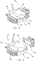
- FIG. 1 an exemplary embodiment of a vehicle-mounted crash attenuator 10, constructed in accordance with the principles of the present invention, attached to the rear 14 of a vehicle or truck 12.
- the crash attenuator 10 is shown in its horizontal deployed orientation, as is also the case in Fig. 8 .
- Figs. 6 and 7 the crash attenuator 10 is shown in its upright storage or transport orientation.
- Figs. 2-8 illustrate the constructional details of the exemplary illustrated crash attenuator 10.
- the crash attenuator 10 is similar in many respects to that disclosed in commonly assigned U.S. Patent No. 6,581,992 (the '992 Patent) except that it is more compactly designed, which is particularly advantageous particularly for applications in congested metropolitan or urban areas, where roadway space is at a premium and tighter turning radii are required or at least preferred. More particularly, while the crash attenuator in the '992 Patent comprises both a strut portion 116 and a cartridge portion 118, as shown, for example, in Fig.
- the crash attenuator 10 of the present invention comprises only a cartridge portion 16, meaning that the length of the attenuator 10 is reduced to about 8 feet (approximately 2,4384 meters), as opposed to about 13 feet (approximately 3.9624 meters) in other versions of the crash attenuator disclosed, for example, in the '992 Patent.
- the crash attenuator 10 may be utilized with a host vehicle 12 of as little as 7000 - 7500 lb. (approximately 3200 - 3500 kg), giving up to 50 MPH (80 KPH) protection with smaller host vehicles.
- Figs. 6-8 show the crash attenuator 10 in its horizontal, deployed orientation ( Fig. 8 ) and in its vertical, stored orientation ( Figs. 6 and 7 ), wherein the cartridge portion is elevated to an approximately 90 degree angle relative to the orientation of the vehicle (a "single 90-degree fold").
- Actuators are provided as part of the backup system 26 for pivoting the cartridge portion 16 and associated components between its deployed and stored orientations.
- the cartridge portion 16 comprises a pair of vertically spaced curved members 18, which in exemplary embodiments comprise aluminum tubing, such as tubing having a 4 1 ⁇ 2 inch (approximately 0.1143 meters) diameter, though other materials, sizes, and configurations having suitable similar properties can be used.
- Mounted on the cartridge portion 16 are energy-absorbing modules 20, 22, and 24. These modules, in exemplary embodiments, are constructed to comprise aluminum honeycomb material disposed in environmentally sealed aluminum containers.
- the aluminum honeycomb material may comprise 1 inch cells in modules 22 and 24, and 1 ⁇ 2 inch (approximately 0.0127 meters) cells in module 20. Of course, alternative materials and cell sizes may be selected, if desired.
- the honeycomb material may include spaced holes stamped in the middle of the assembly, for venting air trapped in the honeycomb, which has been found to improve stability when an onset force is applied to the crash attenuator 10.
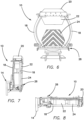
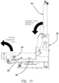
- the backup frame 28 of the backup system 26 is moved by actuator system 42 from the horizontal orientation shown in Fig. 11 to the vertical orientation shown in Fig. 10 , pivoting about the pivot axis 34, as shown by the arrow in Fig. 11 .
- the anti-underride lockout frame members 32 are actuated from their stowed vertical orientation shown in Fig. 11 to the horizontal orientation shown in Fig. 10 , about the pivot joints 40, as shown by the second arrow in Fig. 11 .
- lockout frame members 32 When the lockout frame members 32 are in their deployed horizontal orientations, bolt heads 38 on the end of each frame member 32 engage the backup frame 28, to provide a resisting force against the force of an impacting vehicle, as shown by the arrows in Fig. 10 .
- the bolt heads may be adjusted, using the threaded engagement with the bolt, to optimize the engagement.
- the lockout frame arms 32 provide two points of contact with the backup frame directly above the pivot points 34.
- the force with which a vehicle strikes the crash attenuator is generally located some distance "D" ( Fig. 10 ) above the pivot axis of the mounting system. If the lockout frame were not present, an angular acceleration would be developed about the pivot axis, which would cause the backup frame and system to rotate. This rotation would then allow the impact surface of the attenuator to lift, and thus potentially allow the impacting vehicle to underride.
- the lockout frame 32 provides a resisting force that does not allow this rotation to occur.
Landscapes
- Engineering & Computer Science (AREA)
- Mechanical Engineering (AREA)
- Architecture (AREA)
- Civil Engineering (AREA)
- Structural Engineering (AREA)
- Vibration Dampers (AREA)
- Lighting Device Outwards From Vehicle And Optical Signal (AREA)
Description
- This invention relates to attenuators which are particularly adapted for the absorption of energy in the event of an impact between an errant vehicle and a second, typically stationary or slow-moving vehicle, in the hope of minimizing injury to the occupants of both vehicles, and, more specifically, to vehicle-mounted crash attenuators. Such crash attenuators are disclosed in commonly assigned
U.S. Patent Nos. 6,581,992 , entitled Truck Mounted Crash Attenuator, and7,438,337 , entitled Vehicular Crash Attenuator.US6186565B1 also discloses a lift apparatus for mounting on a vehicle having a support frame extending outward for supporting an attenuator cushion. - While the Applicant has sold many of the attenuators described and claimed in the aforementioned patents under the registered trademark SCORPION®, development has been ongoing on the products to ensure that they meet and exceed always-evolving government crash test standards and are adapted to a wide variety of roadwork applications. The invention described and claimed herein provides improvements designed to make an outstanding product even more useful in metropolitan and urban areas where space and roadway clearance may be at a premium, though, of course, the described systems may be used in any suitable application.
- The present invention is as defined in the appended claims. The invention, together with additional features and advantages thereof, may best be understood by reference to the following description taken in conjunction with the accompanying illustrative drawing.
- In one aspect of the invention, a crash impact attenuator is provided which adapted for deployment on a vehicle, and comprises a cartridge portion comprising at least one energy absorbing module, as well as a backup system having a backup frame, which is adapted to attach the cartridge portion to the vehicle. The backup system comprises an actuator configured to pivot the cartridge portion between a deployed orientation and a stored orientation about a pivot axis disposed on a lower half of the backup system. The backup system further comprises an innovative lockout frame member having a contact surface on one end thereof, the lockout frame member being actuatable between a deployed orientation wherein the contact surface engages a portion of the backup frame and a stowed orientation wherein the contact surface is not engaged with the backup frame.
- In the illustrated embodiments, the cartridge portion is horizontal when in its deployed orientation and vertical when in its stowed orientation. The lockout frame member is horizontal when in its deployed orientation and vertical when in its stowed orientation. The backup frame pivots between a vertical orientation, when the cartridge portion is in its deployed orientation and a horizontal orientation when the cartridge portion is in its stowed orientation.
- The portion of the backup frame contacted by the lockout frame member contact surface is located above the pivot axis. This arrangement permits the backup frame to be reinforced in the event of a vehicular impact, so that it does not collapse about the pivot axis under the force of the impact. In the illustrated embodiment, the pivot axis is located below the location of a resolved force created by an impacting vehicle, while the contact engagement between the backup frame and the lockout frame member is located above the location of the resolved impact force.
- According to the invention, the lockout frame member contact surface is adjustable in order to optimize engagement with the backup frame. For example, the lockout frame member contact surface may comprise an adjustable bolt head which may be threaded to extend or reduce the length of the lockout frame member.
- A second lockout frame member is present in the illustrated embodiment, having a second contact surface adapted to engage a second portion of the backup frame. This provides a more uniform reinforcement across the width of the backup frame. The number of lockout frame members may be optimized to suit different circumstances and operating conditions. As noted above, the portion of the backup frame contacted by the lockout frame member contact surface is located on an upper half of the backup frame.
- In another aspect of the invention, there is described a method of deploying a crash impact attenuator disposed on a rear portion of a host vehicle. The method comprises pivoting a backup frame joining a cartridge portion of the crash impact attenuator to the host vehicle from a horizontal orientation to a vertical orientation and simultaneously pivoting the cartridge portion from a stowed orientation to a deployed orientation, wherein the cartridge portion extends horizontally behind the rear portion of the host vehicle. The pivoting of the backup frame and cartridge portion occurs about a pivot axis disposed along a lower half of the backup frame. A further method step comprises moving a lockout frame member from a stowed orientation to a deployed orientation, so that a contact surface on one end of the lockout frame member engages a portion of the backup frame.
- In the described method, the step of pivoting the backup frame is performed prior to the step of moving the lockout frame member. According to the invention, a further step comprises adjusting a position of the contact surface to optimize engagement with the portion of the backup frame, which step may be performed by threading a bolt head to extend or reduce a length of the lockout frame member.
- The step of moving the lockout frame member may further comprise moving a second lockout frame member, so that a second contact surface on one end of the second lockout frame member engages a second portion of the backup frame.
- The step of moving the lockout frame member may comprise pivoting the lockout frame member from its stowed position, which is vertical, to its deployed position, which is horizontal. As noted above, the portion of the backup frame engaged by the contact surface of the lockout frame member is located above the pivot axis.
-
-
Fig. 1 is a side view of a vehicle, such as a truck, which is equipped with an exemplary embodiment of a vehicle-mounted crash attenuator constructed in accordance with the principles of the present invention; -
Fig. 2 is a perspective view of an exemplary embodiment of the vehicle-mounted crash attenuator shown inFig. 1 ; -
Fig. 3 is a top view of the crash attenuator shown inFig. 2 ; -
Fig. 4 is a side view of the crash attenuator shown inFigs. 2-3 ; -
Fig. 5 is a perspective view, wherein the crash attenuator is illustrated as being disassembled from the backup system for securing the crash attenuator to a vehicle; -
Fig. 6 is a rear view of the crash attenuator shown inFigs. 2-6 , in an upright storage or transport orientation; -
Fig. 7 is a side view of the crash attenuator ofFig. 6 , again in the upright storage or transport orientation; -
Fig. 8 is a side view of the crash attenuator ofFigs. 6 and 7 , in a horizontal deployed orientation; -
Fig. 9 is an isometric view of an exemplary embodiment of a bottom pivot attenuator mounting system or backup system, such as the backup system shown inFig. 5 , for use in the crash attenuator system of the present invention; -
Fig. 10 is a schematic view of the backup system shown inFig. 9 in a deployed position; -
Fig. 11 is a schematic view of the backup system shown inFigs. 9 and10 , in a stowed position; -
Fig. 12 is a schematic isometric view of the backup system shown inFigs. 9-11 , from a reverse orientation respective to that ofFig. 9 ; and -
Fig. 13 is a schematic illustration from above of the backup system shown inFigs. 9-12 , including detail sections of the lockout frame contact surfaces. - Referring now to the figures, wherein like reference numerals refer to like elements throughout the figures, there is shown in
Fig. 1 an exemplary embodiment of a vehicle-mountedcrash attenuator 10, constructed in accordance with the principles of the present invention, attached to the rear 14 of a vehicle ortruck 12. InFig. 1 , thecrash attenuator 10 is shown in its horizontal deployed orientation, as is also the case inFig. 8 . InFigs. 6 and 7 , thecrash attenuator 10 is shown in its upright storage or transport orientation. -
Figs. 2-8 illustrate the constructional details of the exemplary illustratedcrash attenuator 10. Thecrash attenuator 10 is similar in many respects to that disclosed in commonly assignedU.S. Patent No. 6,581,992 (the '992 Patent) except that it is more compactly designed, which is particularly advantageous particularly for applications in congested metropolitan or urban areas, where roadway space is at a premium and tighter turning radii are required or at least preferred. More particularly, while the crash attenuator in the '992 Patent comprises both a strut portion 116 and a cartridge portion 118, as shown, for example, inFig. 10 of the '992 Patent, thecrash attenuator 10 of the present invention comprises only acartridge portion 16, meaning that the length of theattenuator 10 is reduced to about 8 feet (approximately 2,4384 meters), as opposed to about 13 feet (approximately 3.9624 meters) in other versions of the crash attenuator disclosed, for example, in the '992 Patent. Thecrash attenuator 10 may be utilized with ahost vehicle 12 of as little as 7000 - 7500 lb. (approximately 3200 - 3500 kg), giving up to 50 MPH (80 KPH) protection with smaller host vehicles. -
Figs. 6-8 show thecrash attenuator 10 in its horizontal, deployed orientation (Fig. 8 ) and in its vertical, stored orientation (Figs. 6 and 7 ), wherein the cartridge portion is elevated to an approximately 90 degree angle relative to the orientation of the vehicle (a "single 90-degree fold"). Actuators are provided as part of thebackup system 26 for pivoting thecartridge portion 16 and associated components between its deployed and stored orientations. - The
cartridge portion 16 comprises a pair of vertically spacedcurved members 18, which in exemplary embodiments comprise aluminum tubing, such as tubing having a 4 ½ inch (approximately 0.1143 meters) diameter, though other materials, sizes, and configurations having suitable similar properties can be used. Mounted on thecartridge portion 16 are energy-absorbingmodules modules module 20. Of course, alternative materials and cell sizes may be selected, if desired. The honeycomb material may include spaced holes stamped in the middle of the assembly, for venting air trapped in the honeycomb, which has been found to improve stability when an onset force is applied to thecrash attenuator 10. - The
crash attenuator 10 is adapted for attachment to abackup system 26 disposed on therear end 14 of thevehicle 12. Thebackup system 26, in exemplary embodiments, is constructed of a rigid material such as steel, but can be made of other similar materials as well. - In
Fig. 5 , a first type ofbackup system 26 is illustrated for use with thecartridge portion 16. This first type ofbackup system 26 is a "low-pivot" backup system, and will be described further hereinbelow, in conjunction with a description of Figs. 10-14. The system may also be used with a "high-pivot" backup system, of a type more like those used, for example, in the systems shown in the '992 Patent. - A particular advantage of the inventive low-
pivot backup system 26, as shown inFigs. 5 and9-13 , is that it advantageously permits stored vertical height of thesystem 10, as shown inFigs. 7 and9 , to be under 10 feet (approximately 3.048 meeters), whereas with a high-pivot backup system, the stored vertical height of thesystem 10 is over 11 feet (approximately 3.3528 meeters) Additionally, Applicant has advantageously found that the inventive low-pivot backup system operates to inhibit underride of an impacting vehicle beneath thecrash attenuator 10, which can otherwise be particularly dangerous to occupants of the impacting vehicle. - Now with reference particularly to
Figs. 9-13 , the low-pivot backup system 26 is illustrated in greater detail. Thebackup system 26 comprises abackup frame 28, for attachment to thecrash attenuator 10, atruck side frame 30, for attachment to a truck/vehicle 12, and anti-underridelockout frame members 32.Fig. 10 illustrates thebackup system 26 in its deployed orientation, whileFig. 11 illustrates thebackup system 26 in its stowed orientation. - In operation, when deploying the
crash attenuator 10 from the stowed position shown inFig. 11 to the deployed position shown inFig. 10 , thebackup frame 28 of thebackup system 26 is moved byactuator system 42 from the horizontal orientation shown inFig. 11 to the vertical orientation shown inFig. 10 , pivoting about thepivot axis 34, as shown by the arrow inFig. 11 . Once thebackup frame 28 is upright, the anti-underridelockout frame members 32 are actuated from their stowed vertical orientation shown inFig. 11 to the horizontal orientation shown inFig. 10 , about the pivot joints 40, as shown by the second arrow inFig. 11 . When thelockout frame members 32 are in their deployed horizontal orientations, bolt heads 38 on the end of eachframe member 32 engage thebackup frame 28, to provide a resisting force against the force of an impacting vehicle, as shown by the arrows inFig. 10 . The bolt heads may be adjusted, using the threaded engagement with the bolt, to optimize the engagement. Thelockout frame arms 32 provide two points of contact with the backup frame directly above the pivot points 34. - The force with which a vehicle strikes the crash attenuator is generally located some distance "D" (
Fig. 10 ) above the pivot axis of the mounting system. If the lockout frame were not present, an angular acceleration would be developed about the pivot axis, which would cause the backup frame and system to rotate. This rotation would then allow the impact surface of the attenuator to lift, and thus potentially allow the impacting vehicle to underride. Thelockout frame 32 provides a resisting force that does not allow this rotation to occur. - Accordingly, although an exemplary embodiment of the invention has been shown and described, it is to be understood that all the terms used herein are descriptive rather than limiting, and that many changes, modifications, and substitutions may be made by one having ordinary skill in the art without departing from the scope of the invention as claimed.
Claims (13)
- A crash impact attenuator (10) adapted for deployment on a vehicle (12), comprising:a cartridge portion (16) comprising at least one energy absorbing module;a backup system (26) having a backup frame (28) and being adapted to attach the cartridge portion (16) to the vehicle (12), comprising an actuator (42) configured to pivot the cartridge portion (16) between a deployed orientation and a stored orientation about a pivot axis (34) disposed on a lower half of the backup system (26), the backup system further comprising a lockout frame member (32) having a contact surface on one end thereof, the lockout frame member (32) being actuatable between a deployed orientation wherein the contact surface engages a portion of the backup frame (28) and a stowed orientation wherein the contact surface is not engaged with the backup frame (28) and characterized in thatthe lockout frame member contact (32) surface is adjustable in order to optimize engagement with the backup frame (28).
- The crash impact attenuator as recited in claim 1, wherein the cartridge portion (16) is horizontal when in its deployed orientation and vertical when in its stowed orientation.
- The crash impact attenuator as recited in claim 1, wherein the lockout frame member (32) is horizontal when in its deployed orientation and vertical when in its stowed orientation.
- The crash impact attenuator as recited in claim 1, wherein the backup frame (28) pivots between a vertical orientation, when the cartridge portion (16) is in its deployed orientation and a horizontal orientation when the cartridge portion (16) is in its stowed orientation.
- The crash impact attenuator as recited in claim 1, wherein the portion of the backup frame (28) contacted by the lockout frame member (32) contact surface is located above the pivot axis (34).
- The crash impact attenuator as recited in claim 1, wherein the lockout frame member (32) contact surface comprises an adjustable bolt head (38).
- The crash impact attenuator as recited in claim 1, and further comprising a second lockout frame member (32) having a second contact surface adapted to engage a second portion of the backup frame (28).
- The crash impact attenuator as recited in claim 1, wherein the portion of the backup frame (28) contacted by the lockout frame member contact surface is located on an upper half of the backup frame (28).
- A method of deploying a crash impact attenuator (10) disposed on a rear portion of a host vehicle (12), comprising:pivoting a backup frame (28) joining a cartridge portion (16) of the crash impact attenuator to the host vehicle from a horizontal orientation to a vertical orientation and simultaneously pivoting the cartridge portion (16) from a stowed orientation to a deployed orientation, wherein the cartridge portion (16) extends horizontally behind the rear portion of the host vehicle (12), the pivoting of the backup frame (28) and cartridge portion (16) occurring about a pivot axis (34) disposed along a lower half of the backup frame (28); andmoving a lockout frame member (32) from a stowed orientation to a deployed orientation, so that a contact surface on one end of the lockout frame member (32) engages a portion of the backup frame (28) characterized by:
a step of adjusting a position of the contact surface to optimize engagement with the portion of the backup frame (28). - The method as recited in claim 9, wherein the step of pivoting the backup frame (28) is performed prior to the step of moving the lockout frame member (32).
- The method as recited in claim 9, wherein the adjusting step is performed by threading a bolt head (38) to extend or reduce a length of the lockout frame member (32).
- The method as recited in claim 9 wherein the step of moving the lockout frame member (32) further comprises moving a second lockout frame (32) member, so that a second contact surface on one end of the second lockout frame (32) member engages a second portion of the backup frame (28).
- The method as recited in claim 9, wherein the step of moving the lockout frame member (32) comprises pivoting the lockout frame member (32) from its stowed position, which is vertical, to its deployed position, which is horizontal.
Applications Claiming Priority (2)
| Application Number | Priority Date | Filing Date | Title |
|---|---|---|---|
| US202063018970P | 2020-05-01 | 2020-05-01 | |
| PCT/US2021/029561 WO2021222356A1 (en) | 2020-05-01 | 2021-04-28 | Vehicle-mounted crash attenuator |
Publications (4)
| Publication Number | Publication Date |
|---|---|
| EP4143383A1 EP4143383A1 (en) | 2023-03-08 |
| EP4143383A4 EP4143383A4 (en) | 2024-05-08 |
| EP4143383B1 true EP4143383B1 (en) | 2025-07-09 |
| EP4143383C0 EP4143383C0 (en) | 2025-07-09 |
Family
ID=78292476
Family Applications (1)
| Application Number | Title | Priority Date | Filing Date |
|---|---|---|---|
| EP21797203.3A Active EP4143383B1 (en) | 2020-05-01 | 2021-04-28 | Vehicle-mounted crash attenuator |
Country Status (8)
| Country | Link |
|---|---|
| US (5) | US11247624B2 (en) |
| EP (1) | EP4143383B1 (en) |
| JP (1) | JP7471448B2 (en) |
| KR (1) | KR102660585B1 (en) |
| CN (1) | CN115485434B (en) |
| AU (1) | AU2021265111B2 (en) |
| CA (1) | CA3179875A1 (en) |
| WO (1) | WO2021222356A1 (en) |
Families Citing this family (2)
| Publication number | Priority date | Publication date | Assignee | Title |
|---|---|---|---|---|
| US11400884B1 (en) * | 2018-09-26 | 2022-08-02 | Traffix Devices, Inc. | Vehicle-mounted crash attenuator |
| US12384313B1 (en) * | 2022-05-26 | 2025-08-12 | J Travis McCain | Attenuator mounting system and method of use |
Family Cites Families (16)
| Publication number | Priority date | Publication date | Assignee | Title |
|---|---|---|---|---|
| US3907353A (en) | 1974-05-13 | 1975-09-23 | Arthur M Dinitz | Adjustable bumper including protection against under-ride |
| US5052732A (en) * | 1990-04-02 | 1991-10-01 | Renco Supply, Inc. | Crash attenuator utilizing fibrous honeycomb material |
| US6186565B1 (en) * | 1998-10-28 | 2001-02-13 | Albert W. Unrath | Lift apparatus for attenuator cushion |
| US6581992B1 (en) * | 1999-04-28 | 2003-06-24 | Traffix Devices, Inc. | Truck mounted crash attenuator |
| DE10005223C1 (en) * | 2000-02-05 | 2001-08-23 | Michael Rossmann | Device for the mechanical coupling of mutual movement dependencies of a crash cushion and a barrier panel |
| US20030077119A1 (en) * | 2001-09-28 | 2003-04-24 | Energy Absorption System, Inc. | Vehicle mounted crash attenuator |
| CN1805869A (en) * | 2003-04-17 | 2006-07-19 | 能量吸收系统公司 | Mount for truck mounted attenuator |
| US7802829B2 (en) | 2007-01-30 | 2010-09-28 | Traffix Devices, Inc. | Trailer mounted crash attenuator |
| KR101022784B1 (en) * | 2009-08-19 | 2011-03-17 | 한국과학기술원 | Variable length vehicle shock absorber |
| SG11201601724TA (en) * | 2013-09-11 | 2016-04-28 | Energy Absorption System | Crash attenuator |
| KR101614601B1 (en) | 2014-05-09 | 2016-04-21 | 김영훈 | A crash cushion system of vehicles |
| JP6114772B2 (en) | 2015-03-19 | 2017-04-12 | 有限会社小田切車体 | Rear bumper for asphalt finisher |
| CN105346489B (en) * | 2015-12-14 | 2017-08-01 | 吉林大学 | A kind of marmem automobile intelligent endergonic structure and its control method |
| ITUA20162276A1 (en) | 2016-04-04 | 2017-10-04 | Pasquale Impero | IMPACT ATTENUATOR FIXABLE TO THE REAR SIDE OF A TRUCK |
| CN112265488B (en) | 2020-10-15 | 2025-06-10 | 中山市易路美道路养护科技有限公司 | Anti-collision buffer vehicle applied to road construction operation |
| CN112319405A (en) | 2020-11-23 | 2021-02-05 | 张家港市沙洲车辆有限公司 | Anti-collision vehicle for high-speed maintenance |
-
2021
- 2021-04-28 US US17/242,573 patent/US11247624B2/en active Active
- 2021-04-28 EP EP21797203.3A patent/EP4143383B1/en active Active
- 2021-04-28 CN CN202180030286.6A patent/CN115485434B/en active Active
- 2021-04-28 WO PCT/US2021/029561 patent/WO2021222356A1/en not_active Ceased
- 2021-04-28 US US17/926,869 patent/US12139084B2/en active Active
- 2021-04-28 CA CA3179875A patent/CA3179875A1/en active Pending
- 2021-04-28 AU AU2021265111A patent/AU2021265111B2/en active Active
- 2021-04-28 JP JP2022563219A patent/JP7471448B2/en active Active
- 2021-04-28 KR KR1020227039478A patent/KR102660585B1/en active Active
-
2022
- 2022-01-17 US US17/577,299 patent/US11648897B2/en active Active
-
2023
- 2023-04-21 US US18/137,981 patent/US12304409B2/en active Active
-
2025
- 2025-05-19 US US19/212,354 patent/US20260008425A1/en active Pending
Also Published As
| Publication number | Publication date |
|---|---|
| KR102660585B1 (en) | 2024-04-24 |
| JP7471448B2 (en) | 2024-04-19 |
| AU2021265111B2 (en) | 2025-12-04 |
| US12139084B2 (en) | 2024-11-12 |
| US20220134982A1 (en) | 2022-05-05 |
| EP4143383A4 (en) | 2024-05-08 |
| AU2021265111A1 (en) | 2022-11-10 |
| US11648897B2 (en) | 2023-05-16 |
| JP2023522686A (en) | 2023-05-31 |
| CN115485434B (en) | 2025-01-14 |
| CN115485434A (en) | 2022-12-16 |
| US12304409B2 (en) | 2025-05-20 |
| US20260008425A1 (en) | 2026-01-08 |
| KR20220166352A (en) | 2022-12-16 |
| US20210339695A1 (en) | 2021-11-04 |
| US20230192021A1 (en) | 2023-06-22 |
| EP4143383A1 (en) | 2023-03-08 |
| WO2021222356A1 (en) | 2021-11-04 |
| US11247624B2 (en) | 2022-02-15 |
| US20230331179A1 (en) | 2023-10-19 |
| CA3179875A1 (en) | 2021-11-04 |
| EP4143383C0 (en) | 2025-07-09 |
Similar Documents
| Publication | Publication Date | Title |
|---|---|---|
| US20260008425A1 (en) | Vehicle-mounted crash attenuator | |
| US6581992B1 (en) | Truck mounted crash attenuator | |
| EP0795440B1 (en) | Highway crash cushion | |
| AU761337B2 (en) | Method for decelerating a vehicle, highway crash cushion, and energy absorbing element therefor | |
| US6942263B2 (en) | Mount for truck mounted attenuator | |
| CA2923559C (en) | Crash attenuator | |
| AU2002329948B2 (en) | Vehicle Mounted Crash Attenuator | |
| EP1842746B1 (en) | A bonnet for a vehicle | |
| US7243964B1 (en) | Truck mounted crash attenuator | |
| US20260009193A1 (en) | Vehicle-mounted attenuator | |
| US20260009194A1 (en) | Vehicle-mounted attenuator | |
| US20260009192A1 (en) | Vehicle-mounted attenuator | |
| CN119754194A (en) | Assembled anti-collision guardrail with built-in paper folding structure energy absorption buffer device | |
| HK1073342A (en) | Vehicle mounted crash attenuator | |
| HK1224260B (en) | Crash attenuator and method of attenuating energy from impacting vehicle with same |
Legal Events
| Date | Code | Title | Description |
|---|---|---|---|
| STAA | Information on the status of an ep patent application or granted ep patent |
Free format text: STATUS: THE INTERNATIONAL PUBLICATION HAS BEEN MADE |
|
| PUAI | Public reference made under article 153(3) epc to a published international application that has entered the european phase |
Free format text: ORIGINAL CODE: 0009012 |
|
| STAA | Information on the status of an ep patent application or granted ep patent |
Free format text: STATUS: REQUEST FOR EXAMINATION WAS MADE |
|
| 17P | Request for examination filed |
Effective date: 20221129 |
|
| AK | Designated contracting states |
Kind code of ref document: A1 Designated state(s): AL AT BE BG CH CY CZ DE DK EE ES FI FR GB GR HR HU IE IS IT LI LT LU LV MC MK MT NL NO PL PT RO RS SE SI SK SM TR |
|
| DAV | Request for validation of the european patent (deleted) | ||
| DAX | Request for extension of the european patent (deleted) | ||
| P01 | Opt-out of the competence of the unified patent court (upc) registered |
Effective date: 20230529 |
|
| A4 | Supplementary search report drawn up and despatched |
Effective date: 20240410 |
|
| RIC1 | Information provided on ipc code assigned before grant |
Ipc: B60D 1/24 20060101ALI20240404BHEP Ipc: F16F 7/12 20060101ALI20240404BHEP Ipc: B60R 19/00 20060101ALI20240404BHEP Ipc: E01F 15/14 20060101AFI20240404BHEP |
|
| GRAP | Despatch of communication of intention to grant a patent |
Free format text: ORIGINAL CODE: EPIDOSNIGR1 |
|
| STAA | Information on the status of an ep patent application or granted ep patent |
Free format text: STATUS: GRANT OF PATENT IS INTENDED |
|
| INTG | Intention to grant announced |
Effective date: 20250328 |
|
| GRAS | Grant fee paid |
Free format text: ORIGINAL CODE: EPIDOSNIGR3 |
|
| GRAA | (expected) grant |
Free format text: ORIGINAL CODE: 0009210 |
|
| STAA | Information on the status of an ep patent application or granted ep patent |
Free format text: STATUS: THE PATENT HAS BEEN GRANTED |
|
| AK | Designated contracting states |
Kind code of ref document: B1 Designated state(s): AL AT BE BG CH CY CZ DE DK EE ES FI FR GB GR HR HU IE IS IT LI LT LU LV MC MK MT NL NO PL PT RO RS SE SI SK SM TR |
|
| REG | Reference to a national code |
Ref country code: GB Ref legal event code: FG4D |
|
| REG | Reference to a national code |
Ref country code: CH Ref legal event code: EP |
|
| REG | Reference to a national code |
Ref country code: IE Ref legal event code: FG4D |
|
| REG | Reference to a national code |
Ref country code: DE Ref legal event code: R096 Ref document number: 602021033882 Country of ref document: DE |
|
| U01 | Request for unitary effect filed |
Effective date: 20250721 |
|
| U07 | Unitary effect registered |
Designated state(s): AT BE BG DE DK EE FI FR IT LT LU LV MT NL PT RO SE SI Effective date: 20250728 |
|
| PG25 | Lapsed in a contracting state [announced via postgrant information from national office to epo] |
Ref country code: IS Free format text: LAPSE BECAUSE OF FAILURE TO SUBMIT A TRANSLATION OF THE DESCRIPTION OR TO PAY THE FEE WITHIN THE PRESCRIBED TIME-LIMIT Effective date: 20251109 |
|
| PG25 | Lapsed in a contracting state [announced via postgrant information from national office to epo] |
Ref country code: NO Free format text: LAPSE BECAUSE OF FAILURE TO SUBMIT A TRANSLATION OF THE DESCRIPTION OR TO PAY THE FEE WITHIN THE PRESCRIBED TIME-LIMIT Effective date: 20251009 |
|
| PG25 | Lapsed in a contracting state [announced via postgrant information from national office to epo] |
Ref country code: HR Free format text: LAPSE BECAUSE OF FAILURE TO SUBMIT A TRANSLATION OF THE DESCRIPTION OR TO PAY THE FEE WITHIN THE PRESCRIBED TIME-LIMIT Effective date: 20250709 |
|
| PG25 | Lapsed in a contracting state [announced via postgrant information from national office to epo] |
Ref country code: GR Free format text: LAPSE BECAUSE OF FAILURE TO SUBMIT A TRANSLATION OF THE DESCRIPTION OR TO PAY THE FEE WITHIN THE PRESCRIBED TIME-LIMIT Effective date: 20251010 |
|
| PG25 | Lapsed in a contracting state [announced via postgrant information from national office to epo] |
Ref country code: PL Free format text: LAPSE BECAUSE OF FAILURE TO SUBMIT A TRANSLATION OF THE DESCRIPTION OR TO PAY THE FEE WITHIN THE PRESCRIBED TIME-LIMIT Effective date: 20250709 |
|
| PG25 | Lapsed in a contracting state [announced via postgrant information from national office to epo] |
Ref country code: RS Free format text: LAPSE BECAUSE OF FAILURE TO SUBMIT A TRANSLATION OF THE DESCRIPTION OR TO PAY THE FEE WITHIN THE PRESCRIBED TIME-LIMIT Effective date: 20251009 |
|
| U1N | Appointed representative for the unitary patent procedure changed after the registration of the unitary effect |
Representative=s name: AVIDITY IP; GB |
|
| PG25 | Lapsed in a contracting state [announced via postgrant information from national office to epo] |
Ref country code: ES Free format text: LAPSE BECAUSE OF FAILURE TO SUBMIT A TRANSLATION OF THE DESCRIPTION OR TO PAY THE FEE WITHIN THE PRESCRIBED TIME-LIMIT Effective date: 20250709 |
|
| PG25 | Lapsed in a contracting state [announced via postgrant information from national office to epo] |
Ref country code: SM Free format text: LAPSE BECAUSE OF FAILURE TO SUBMIT A TRANSLATION OF THE DESCRIPTION OR TO PAY THE FEE WITHIN THE PRESCRIBED TIME-LIMIT Effective date: 20250709 |
|
| PG25 | Lapsed in a contracting state [announced via postgrant information from national office to epo] |
Ref country code: CZ Free format text: LAPSE BECAUSE OF FAILURE TO SUBMIT A TRANSLATION OF THE DESCRIPTION OR TO PAY THE FEE WITHIN THE PRESCRIBED TIME-LIMIT Effective date: 20250709 |
|
| PG25 | Lapsed in a contracting state [announced via postgrant information from national office to epo] |
Ref country code: SK Free format text: LAPSE BECAUSE OF FAILURE TO SUBMIT A TRANSLATION OF THE DESCRIPTION OR TO PAY THE FEE WITHIN THE PRESCRIBED TIME-LIMIT Effective date: 20250709 |