EP4143374B1 - Needle bar tensioning apparatus - Google Patents
Needle bar tensioning apparatus Download PDFInfo
- Publication number
- EP4143374B1 EP4143374B1 EP21796435.2A EP21796435A EP4143374B1 EP 4143374 B1 EP4143374 B1 EP 4143374B1 EP 21796435 A EP21796435 A EP 21796435A EP 4143374 B1 EP4143374 B1 EP 4143374B1
- Authority
- EP
- European Patent Office
- Prior art keywords
- shaft
- shifter
- defines
- needle bar
- longitudinal dimension
- Prior art date
- Legal status (The legal status is an assumption and is not a legal conclusion. Google has not performed a legal analysis and makes no representation as to the accuracy of the status listed.)
- Active
Links
Images




Classifications
-
- D—TEXTILES; PAPER
- D05—SEWING; EMBROIDERING; TUFTING
- D05C—EMBROIDERING; TUFTING
- D05C15/00—Making pile fabrics or articles having similar surface features by inserting loops into a base material
- D05C15/04—Tufting
- D05C15/08—Tufting machines
- D05C15/16—Arrangements or devices for manipulating threads
- D05C15/20—Arrangements or devices, e.g. needles, for inserting loops; Driving mechanisms therefor
-
- D—TEXTILES; PAPER
- D05—SEWING; EMBROIDERING; TUFTING
- D05C—EMBROIDERING; TUFTING
- D05C11/00—Devices for guiding, feeding, handling, or treating the threads in embroidering machines; Machine needles; Operating or control mechanisms therefor
- D05C11/02—Machine needles
- D05C11/06—Needle-driving or control mechanisms
-
- D—TEXTILES; PAPER
- D05—SEWING; EMBROIDERING; TUFTING
- D05C—EMBROIDERING; TUFTING
- D05C15/00—Making pile fabrics or articles having similar surface features by inserting loops into a base material
- D05C15/04—Tufting
- D05C15/08—Tufting machines
- D05C15/26—Tufting machines with provision for producing patterns
- D05C15/30—Tufting machines with provision for producing patterns by moving the tufting tools laterally
Definitions
- the disclosed invention relates to tufting machines and, in particular, to apparatus and methods for adjusting the needle bars of tufting machines.
- Tufting machines such as, for example, conventional Card-Monroe tufting machines, comprise a needle bar having a plurality of needles that are reciprocally plunged through backing to make a tufted article.
- a corresponding hook bar can comprise a plurality of hooks, or "loopers,” that engage the yarn from respective needles to form yarn loops.
- a needle bar shifter assembly can be coupled to each needle bar to shift the needle bar transversely to the movement direction of the backing material in order to form patterns in the tufted article.
- the needle bar shifter assembly can comprise a slide assembly that is coupled to a carriage assembly, and the needle bar can, in turn, be coupled to the carriage assembly.
- An actuator can shift the slide assembly transversely, thereby driving the carriage assemblies transversely.
- Conventional needle bar assemblies used in shifted tufting processes require periodic position adjustment relative to the hook bar in order to maintain a select positioning of the needles relative to the respective hooks.
- the desired spatial relationship between the needles and respective hooks can change based on the different types of yarn being used.
- tufting machines typically have an adjustment (tensioning) system
- a technician using a standard wrench can only access such tensioning systems from a guarded area, thereby slowing the tensioning process.
- technicians frequently use a hammer and/or punch or specialized (crow's foot) wrenches in order to adjust the tension of the needle bar shifter assembly.
- the use of these tools creates additional safety concerns and damages the shifter shaft of the tufting machine.
- the conventional tensioning system uses a coarse thread pitch, so adjustment via the conventional tensioning machine is correspondingly coarse. Thus, the conventional tensioning system lacks precision.
- the needle bar shifter has first, second, third, and fourth shaft segments.
- Each of the first, second, third, and fourth shaft segments has respective first and second ends, the first and second shaft segments being aligned and spaced apart in a longitudinal dimension, the third and fourth shaft segments being aligned and spaced apart in the longitudinal dimension, the first ends of the first and second shaft segments facing one another, the first ends of the third and fourth shaft segments facing one another.
- the third and fourth shaft segments are offset from the first and second shaft segments in a transverse dimension.
- the apparatus further comprises a shifter adjustment assembly configured to couple to the needle bar shifter.
- the shifter adjustment assembly is configured to cause adjustment of a position of a needle bar of the tufting apparatus relative to a hook bar of the tufting apparatus in order to maintain a select positioning of needles of the needle bar relative to respective hooks of the hook bar.
- the shifter adjustment assembly comprises a first body that is configured to couple to the first ends of the first and third shaft segments.
- a second body is configured to couple to the first ends of the second and fourth shaft segments.
- the shifter adjustment assembly comprises a coupling between the first body and the second body.
- the coupling is configured to releasably secure an axial position of the first body with respect to the second body along the longitudinal dimension.
- the first body and second body define respective complementary surfaces that are configured for sliding engagement so that movement between the first body and the second body in the transverse dimension is restricted and movement between the first body and the second body in the longitudinal dimension is permitted.
- the shifter adjustment assembly can further comprise an adjustment device configured to move the first body with respect to the second body in the longitudinal dimension.
- the first body can define a first through-hole that extends through the first body in the longitudinal dimension.
- the second body can define a second through-hole that extends through the second body in the longitudinal dimension.
- the first through-hole can define a right-hand thread.
- the second through-hole can define a left-hand thread.
- the adjustment device can comprise an elongate rod having a right-hand thread on a first end and a left-hand thread on a second end opposite the first end.
- the right-hand thread of the first end of the elongate rod can be in engagement with the right hand thread of the first through-hole
- the left-hand thread of the second end of the elongate rod can be in engagement with the left-hand thread of the second through-hole.
- the shifter adjustment assembly can further comprise a hexagonal head coupled to the elongate rod.
- the adjustment device can further comprise a jam nut that is threadedly movable on the elongate rod and configured to bias against one of the first body or the second body.
- the first body can comprise a first portion and a second portion that is coupled to the first portion.
- the first portion of the first body can define the first through-hole that defines the right-hand thread.
- the second body can comprise a first portion and a second portion that is coupled to the first portion.
- the first portion of the second body can define the second through-hole that defines the left-hand thread.
- the first portion of the first body can extend upwardly from the second portion of the first body.
- the first portion of the second body can extend upwardly from the second portion of the second body
- the coupling between the first body and the second body can comprise at least one fastener.
- One of the first body and the second body can define at least one slot that is elongate in the longitudinal dimension, wherein each fastener of the at least one fastener extends through a respective slot of the at least one slot.
- the first body can define a first longitudinally extending through-bore for receiving the first shaft segment.
- the first body can define a second longitudinally extending through-bore for receiving the third shaft segment.
- the first body can define a first slit that extends between a first side of the first body and the first longitudinally extending through-bore.
- the first body can define a second slit that extends between a second side of the first body and the second longitudinally extending through-bore.
- the shifter adjustment assembly can comprise at least one threaded fastener that extends across the first slit of the first body.
- the at least one threaded fastener that extends across the first slit of the first body can threadedly couple to the first body so that a tightening of the at least one threaded fastener that extends across the first slit of the first body causes the first longitudinally extending through-bore to tighten against the first shaft segment.
- the shifter adjustment assembly can comprise at least one threaded fastener that extends across the second slit of the first body.
- the at least one threaded fastener that extends across the second slit of the first body can threadedly couple to the first body so that a tightening of the at least one threaded fastener that extends across the second slit of the first body causes the second longitudinally extending through-bore to tighten against the third shaft segment.
- the second body can define a first longitudinally extending through-bore for receiving the second shaft segment.
- the second body can define a second longitudinally extending through-bore for receiving the fourth shaft segment.
- the second body can define a first slit that extends between a first side of the second body and the first longitudinally extending through-bore.
- the second body can define a second slit that extends between a first edge of the second body and the second longitudinally extending through-bore.
- the shifter adjustment assembly can comprise at least one threaded fastener that extends across the first slit of the second body.
- the at least one threaded fastener that extends across the first slit of the second body can threadedly couple to the first body so that a tightening of the at least one threaded fastener that extends across the first slit of the second body causes the first longitudinally extending through-bore to tighten against the second shaft segment.
- the shifter adjustment assembly can comprise at least one threaded fastener that extends across the second slit of the second body.
- the at least one threaded fastener that extends across the second slit of the second body can threadedly couple to the first body so that a tightening of the at least one threaded fastener that extends across the second slit of the second body causes the second longitudinally extending through-bore to tighten against the fourth shaft segment.
- the first body can define one of a tongue or a groove
- the second body can define the other of the tongue and the groove.
- the tongue can be receivable into the groove with a clearance in the transverse dimension between the groove and the tongue that inhibits transverse movement between the tongue and the groove.
- the tongue can define first and second longitudinally extending outer edges.
- the groove can define corresponding first and second longitudinally extending inner edges that are outward of the respective outer edge of the first and second outer edges of the tongue relative to the transverse dimension.
- the first and second outer edges of the groove can respectively slidingly engage the first and second inner edges of the tongue to thereby restrict movement between the first body and the second body in the transverse dimension.
- the shifter adjustment assembly can further comprise a linear position sensor that is configured to detect at least one of a distance or a change in distance between the first body and the second body relative to the longitudinal dimension.
- Ranges can be expressed herein as from “about” one particular value, and/or to "about” another particular value. When such a range is expressed, another aspect includes from the one particular value and/or to the other particular value. Similarly, when values are expressed as approximations, by use of the antecedent “about,” it will be understood that the particular value forms another aspect. It will be further understood that the endpoints of each of the ranges are significant both in relation to the other endpoint, and independently of the other endpoint. Optionally, in some aspects, when values are approximated by use of the antecedent "about,” it is contemplated that values within up to 15%, up to 10%, up to 5%, or up to 1% (above or below) of the particularly stated value can be included within the scope of those aspects.
- the terms "optional” or “optionally” mean that the subsequently described event or circumstance may or may not occur, and that the description includes instances where said event or circumstance occurs and instances where it does not.
- the term "at least one of” is intended to be synonymous with “one or more of.”
- “at least one of A, B and C” explicitly includes only A, only B, only C, and combinations of each.
- the shifter 10 comprises a first shaft segment 12 having a first end 14 and an opposing second end 16, a second shaft segment 18 having a first end 20 and an opposing second end 22, a third shaft segment 24 having a first end 26 and an opposing second end 28, and a fourth shaft segment 30 having a first end 32 and an opposing second end 34.
- the first and second shaft segments are aligned and spaced apart in a longitudinal dimension 36, and the first end 14 of the first segment 12 faces the first end 20 of the second shaft segment 18.
- the third and fourth shaft segments is aligned and spaced apart in the longitudinal dimension 36, and the first end 26 of the third segment 24 faces the first end 32 of the fourth shaft segment 30.
- the first and second shaft segments are offset from the third and fourth shaft segments in a transverse dimension 38 that is perpendicular to the longitudinal dimension 36.
- the transverse dimension 38 can be horizontal.
- the disclosed shifter adjuster assemblies can permit faster, safer, and more precise tensioning adjustments in comparison to conventional methods. More particularly, the disclosed shifter adjuster assemblies can be located under the head of the tufting machine, making the location of adjustment easily and safely accessible without the need for entering a guarded area or using tools that cause damage to the shifter shaft. Optionally, the disclosed shifter adjuster assemblies can make use of fine threads that permit more precise tensioning adjustment.
- the shifter adjustment assembly 100 comprises a first body 102 coupled to the first end 14 of the first shaft segment 12 and the first end 26 of the third shaft segment 24.
- the shifter adjustment assembly 100 further comprises a second body 104 coupled to the first end 14 of the second shaft segment 12 and the first end 32 of the fourth shaft segment 30.
- each of the first body 102 and second body 104 can define first and second through-bores 108 on opposing sides.
- Each of the first body and the second body 104 can have opposing first and second sides 113a, 113b.
- a slit 110 can extend inwardly from a respective side (e.g., the first or second side 113a,b) of the respective body to a respective through-bore 108.
- the first body 102 and second body 104 are slidingly coupled so that movement between the first body 102 and the second body 104 in the transverse dimension 38 is restricted, but movement between the first body 102 and the second body 104 in the longitudinal dimension 36 is permitted.
- the first body 102 can define a tongue 120 that can have a first longitudinally extending outer edge 122 and a second longitudinally extending outer edge 124 that is spaced from the first longitudinally extending outer edge 122 in the transverse dimension 38.
- the second body 104 can define a groove 126 having a first longitudinally extending inner edge 128 and a second longitudinally extending inner edge 130.
- the tongue 120 can be receivable into the groove with a small clearance in the transverse dimension between the groove 126 and the tongue 120 to inhibit transverse movement greater than the small clearance between the tongue and the groove.
- the first outer edge 122 of the tongue 120 can slidingly engage the first inner edge 128 of the groove 126
- the second outer edge 124 of the tongue 120 can slidingly engage the second inner edge 130 of the groove.
- the first inner edge 128 of the groove 126 can restrict the movement of the tongue in a first direction relative to the transverse dimension
- the second inner edge 130 of the groove 126 can restrict the movement of the tongue in an opposing second direction relative to the transverse dimension
- the first and second inner edges can guide the longitudinal movement of the tongue 120, and thus, the first body 102.
- a coupling 140 between the first body 102 and the second body 104 can secure the position of the first body with respect to the second body.
- the coupling 140 can comprise one or more fasteners 142 (e.g., screws or bolts) and, optionally, washers 143.
- the tongue 120 of the first body 102 can define one or more slots 144 that are elongate in the longitudinal dimension 36.
- the second body 104 can define respective holes 146 (optionally, threaded holes) that are aligned in the transverse dimension with respective slots 144 along a portion of a longitudinal travel of the first body 102 relative to the second body 104.
- the fasteners 142 can threadedly engage the holes 146.
- the fasteners 142 can be bolts that are bolted through the holes 146 into correspond nuts.
- the fasteners 142 When the fasteners 142 are loosened, the first body 102 can slide relative to the second body 104 along the longitudinal dimension, optionally limited by the length of the slots in the longitudinal dimension.
- the fasteners 142 When the fasteners 142 are tightened down, the first body 102 can be held in a fixed position with respect to the second body.
- the shifter adjustment assembly 100 can comprise an adjustment device 150.
- the first body can define a first through-hole 152 that extends through the first body in the longitudinal dimension.
- the first through-hole 152 can define one at least one right-handed thread.
- the second body 104 can comprise a second through-hole 154.
- the second through-hole 154 can define at least one left-handed thread.
- An elongate rod 156 can have a length, a first end 158, and an opposing second end 160.
- the elongate rod 156 can define right-handed thread(s) 162 on the first end and extending along a portion of the length of the elongate rod 156.
- the elongate rod 156 can define left-handed thread(s) 164 on the second end 160 and extending along a portion of the length of the elongate rod 156.
- the elongate rod can be threadedly coupled to, and extend between, the first body 102 and the second body 104.
- the right-handed thread(s) 162 of the elongate rod 156 can be threaded into the first through hole 152 of the first body, and the left-handed thread(s) 164 of the elongate rod can be threaded into the second hole 154 of the second body.
- Rotation of the elongate rod in a first direction can cause the first body to move away from the second body in the longitudinal dimension, and rotation of the elongate rod in a second direction that is opposite the first direction can cause the first body to move toward the second body.
- the elongate rod can define one or more gripping features, such as, for example, a hexagonal head 166, to facilitate rotation of the elongate rod.
- a nut can be threaded onto one of the ends of the elongate rod 156 and then attached thereto via weldment.
- a jam nut 168 can be threaded onto one of the ends of the elongate rod. The jam nut can be tightened down against a face of the respective body of the first and second body that shares the same thread(s) as the jam nut 168 to inhibit further rotation of the elongate rod with respect to either of the first or second bodies.
- the spacing between the first body 102 and the second body 104 can, in some circumstances, be critical. Accordingly, the clearance between the threads of the first through-hole 152 and the right-handed thread(s) 162, and the clearance between the thread(s) of the second through-hole 154 and the left-handed thread(s) 164 can be minimized so that no (or substantially no) longitudinal movement is allowed between the elongate rod and the first and second bodies.
- the first through-hole 152 and the second through-hole 154 can define Unified Thread Class 3A threads
- the right- and left-handed thread(s) 162, 164 can define Unified Thread Class 2B threads.
- all of the threads can be Class 3A. In this way, the exact spacing between the first and second bodies can be selected.
- the first body 102 can comprise a first portion 170 and a second portion 172 that can be coupled to the first portion (e.g., via screws 176).
- the first portion can define the through-hole 152.
- the first portion 170 of the first body 102 can extend perpendicularly or generally perpendicularly from the second portion 172, such as, for example, vertically upward from an upper face of the second portion 172.
- the second body 104 can comprise a first portion 178 and a second portion 180 that is coupled to the first portion (e.g., via screws 176).
- the first portion 178 of the first body 102 can extend perpendicularly or generally perpendicularly from the second portion 180, such as, for example, vertically upward from an upper face of the second portion 180.
- a linear position sensor 182 (e.g., a linear potentiometer) can be coupled between the first body 102 and the second body 104 so that their positions relative to each other in the longitudinal dimension can be known.
- a first end of the linear position sensor 182 can couple to the first body 102, and a second end of the linear position sensor can couple to the second body 104.
- the linear position sensor can be a capacitive scale having a resolution of, for example, 0.0005 inches.
- the linear position sensor can be in communication with a computing device (e.g., desktop computer, laptop, smartphone, tablet, etc.), a small LED display, or other output device to convey its sensed position to an operator.
- first body 102 can define the groove 126
- second body can comprise the tongue 120
- first body 102 can define the left-handed thread(s) 164
- second body 104 can define the right-handed thread(s) 162.
- both of the original shafts of the shifter of the tufting machine extend along the longitudinal length of the tufting machine.
- the shafts can be cut to provide the first, second, third, and fourth shafts segments.
- the original shafts can be removed and replaced with shorter segments (i.e., the first, second, third, and fourth shaft segments) that, when coupled to the shifter adjustment assembly 100, provide the same length, or substantially the same length, as the original shafts of the shifter assembly.
- the first and third shaft segments can be inserted into the respective through-bores 108 of the first body, and the fasteners 112 can be tightened down.
- the second and fourth shaft segments can be inserted into the respective through-bores 108 of the second body, and the fasteners 112 can be tightened down.
- an operator can first verify that the needles are in an up position and not crossing over any hooks of the tufting machine. It can be desirable for the bracket not to be under tension or compression during adjustment. The tufting machine can be locked out for safety.
- the jam nut 168 can be loosened from against the first or second body, and the slide fasteners 142 can be loosened to enable movement between the first and second body.
- an operator can rotate the tension adjustment nut to adjust the position of the first body relative to the second body in the longitudinal dimension.
- the first and second bodies can be moved toward each other.
- the first and second bodies can be moved away from each other.
- Adjustment between the first and second bodies can shift the needle bar relative to the hook bar, thereby adjusting the positions of the needles with relative to their respective hooks.
- the linear position sensor can output a readout, and the operator can select the relative position between the first and second body based on a desired readout from the linear position sensor.
- the jam nut can be tightened against a respective body.
- the fasteners 142 can be tightened down (e.g., to about 60 ft-lbs) to hold the first and second bodies in their relative positions.
- the tufting machine can be locked out to put the machine back in production.
Landscapes
- Engineering & Computer Science (AREA)
- Textile Engineering (AREA)
- Chemical & Material Sciences (AREA)
- Materials Engineering (AREA)
- Mutual Connection Of Rods And Tubes (AREA)
- Devices For Conveying Motion By Means Of Endless Flexible Members (AREA)
- Sewing Machines And Sewing (AREA)
- Knitting Machines (AREA)
- Arrangement Or Mounting Of Control Devices For Change-Speed Gearing (AREA)
Description
- This application claims priority to
U.S Provisional Application No. 63/015,849, filed April 27, 2020 - The disclosed invention relates to tufting machines and, in particular, to apparatus and methods for adjusting the needle bars of tufting machines.
- Tufting machines, such as, for example, conventional Card-Monroe tufting machines, comprise a needle bar having a plurality of needles that are reciprocally plunged through backing to make a tufted article. A corresponding hook bar can comprise a plurality of hooks, or "loopers," that engage the yarn from respective needles to form yarn loops. A needle bar shifter assembly can be coupled to each needle bar to shift the needle bar transversely to the movement direction of the backing material in order to form patterns in the tufted article. The needle bar shifter assembly can comprise a slide assembly that is coupled to a carriage assembly, and the needle bar can, in turn, be coupled to the carriage assembly. An actuator can shift the slide assembly transversely, thereby driving the carriage assemblies transversely. One embodiment of a shifter assembly is disclosed in
U.S. Patent No. 5,979,344, granted November 9, 1999 to William M. Christman, Jr. Further examples are disclosed inUS 3,026,830 A andUS 4,465,001 A . - Conventional needle bar assemblies used in shifted tufting processes require periodic position adjustment relative to the hook bar in order to maintain a select positioning of the needles relative to the respective hooks. The desired spatial relationship between the needles and respective hooks can change based on the different types of yarn being used.
- Although tufting machines typically have an adjustment (tensioning) system, a technician using a standard wrench can only access such tensioning systems from a guarded area, thereby slowing the tensioning process. Moreover, technicians frequently use a hammer and/or punch or specialized (crow's foot) wrenches in order to adjust the tension of the needle bar shifter assembly. However, the use of these tools creates additional safety concerns and damages the shifter shaft of the tufting machine. Moreover, the conventional tensioning system uses a coarse thread pitch, so adjustment via the conventional tensioning machine is correspondingly coarse. Thus, the conventional tensioning system lacks precision.
- Described herein, in various aspects, is an apparatus comprising a needle bar shifter of a tufting apparatus. The needle bar shifter has first, second, third, and fourth shaft segments. Each of the first, second, third, and fourth shaft segments has respective first and second ends, the first and second shaft segments being aligned and spaced apart in a longitudinal dimension, the third and fourth shaft segments being aligned and spaced apart in the longitudinal dimension, the first ends of the first and second shaft segments facing one another, the first ends of the third and fourth shaft segments facing one another. The third and fourth shaft segments are offset from the first and second shaft segments in a transverse dimension. The apparatus further comprises a shifter adjustment assembly configured to couple to the needle bar shifter. The shifter adjustment assembly is configured to cause adjustment of a position of a needle bar of the tufting apparatus relative to a hook bar of the tufting apparatus in order to maintain a select positioning of needles of the needle bar relative to respective hooks of the hook bar. The shifter adjustment assembly comprises a first body that is configured to couple to the first ends of the first and third shaft segments. A second body is configured to couple to the first ends of the second and fourth shaft segments. The shifter adjustment assembly comprises a coupling between the first body and the second body. The coupling is configured to releasably secure an axial position of the first body with respect to the second body along the longitudinal dimension. The first body and second body define respective complementary surfaces that are configured for sliding engagement so that movement between the first body and the second body in the transverse dimension is restricted and movement between the first body and the second body in the longitudinal dimension is permitted.
- The shifter adjustment assembly can further comprise an adjustment device configured to move the first body with respect to the second body in the longitudinal dimension.
- The first body can define a first through-hole that extends through the first body in the longitudinal dimension. The second body can define a second through-hole that extends through the second body in the longitudinal dimension. The first through-hole can define a right-hand thread. The second through-hole can define a left-hand thread. The adjustment device can comprise an elongate rod having a right-hand thread on a first end and a left-hand thread on a second end opposite the first end. The right-hand thread of the first end of the elongate rod can be in engagement with the right hand thread of the first through-hole, and the left-hand thread of the second end of the elongate rod can be in engagement with the left-hand thread of the second through-hole.
- The shifter adjustment assembly can further comprise a hexagonal head coupled to the elongate rod.
- The adjustment device can further comprise a jam nut that is threadedly movable on the elongate rod and configured to bias against one of the first body or the second body.
- The first body can comprise a first portion and a second portion that is coupled to the first portion. The first portion of the first body can define the first through-hole that defines the right-hand thread. The second body can comprise a first portion and a second portion that is coupled to the first portion. The first portion of the second body can define the second through-hole that defines the left-hand thread.
- The first portion of the first body can extend upwardly from the second portion of the first body. The first portion of the second body can extend upwardly from the second portion of the second body
- The coupling between the first body and the second body can comprise at least one fastener.
- One of the first body and the second body can define at least one slot that is elongate in the longitudinal dimension, wherein each fastener of the at least one fastener extends through a respective slot of the at least one slot.
- The first body can define a first longitudinally extending through-bore for receiving the first shaft segment. The first body can define a second longitudinally extending through-bore for receiving the third shaft segment.
- The first body can define a first slit that extends between a first side of the first body and the first longitudinally extending through-bore. The first body can define a second slit that extends between a second side of the first body and the second longitudinally extending through-bore. The shifter adjustment assembly can comprise at least one threaded fastener that extends across the first slit of the first body. The at least one threaded fastener that extends across the first slit of the first body can threadedly couple to the first body so that a tightening of the at least one threaded fastener that extends across the first slit of the first body causes the first longitudinally extending through-bore to tighten against the first shaft segment. The shifter adjustment assembly can comprise at least one threaded fastener that extends across the second slit of the first body. The at least one threaded fastener that extends across the second slit of the first body can threadedly couple to the first body so that a tightening of the at least one threaded fastener that extends across the second slit of the first body causes the second longitudinally extending through-bore to tighten against the third shaft segment.
- The second body can define a first longitudinally extending through-bore for receiving the second shaft segment. The second body can define a second longitudinally extending through-bore for receiving the fourth shaft segment.
- The second body can define a first slit that extends between a first side of the second body and the first longitudinally extending through-bore. The second body can define a second slit that extends between a first edge of the second body and the second longitudinally extending through-bore. The shifter adjustment assembly can comprise at least one threaded fastener that extends across the first slit of the second body. The at least one threaded fastener that extends across the first slit of the second body can threadedly couple to the first body so that a tightening of the at least one threaded fastener that extends across the first slit of the second body causes the first longitudinally extending through-bore to tighten against the second shaft segment. The shifter adjustment assembly can comprise at least one threaded fastener that extends across the second slit of the second body. The at least one threaded fastener that extends across the second slit of the second body can threadedly couple to the first body so that a tightening of the at least one threaded fastener that extends across the second slit of the second body causes the second longitudinally extending through-bore to tighten against the fourth shaft segment.
- The first body can define one of a tongue or a groove, and the second body can define the other of the tongue and the groove. The tongue can be receivable into the groove with a clearance in the transverse dimension between the groove and the tongue that inhibits transverse movement between the tongue and the groove.
- The tongue can define first and second longitudinally extending outer edges. The groove can define corresponding first and second longitudinally extending inner edges that are outward of the respective outer edge of the first and second outer edges of the tongue relative to the transverse dimension. The first and second outer edges of the groove can respectively slidingly engage the first and second inner edges of the tongue to thereby restrict movement between the first body and the second body in the transverse dimension.
- The shifter adjustment assembly can further comprise a linear position sensor that is configured to detect at least one of a distance or a change in distance between the first body and the second body relative to the longitudinal dimension.
- Additional advantages of the invention will be set forth in part in the description that follows, and in part will be obvious from the description, or may be learned by practice of the invention. The advantages of the invention will be realized and attained by means of the elements and combinations particularly pointed out in the appended claims. It is to be understood that both the foregoing general description and the following detailed description are exemplary and explanatory only and are not restrictive of the invention, as claimed.
- These and other features of the preferred embodiments of the invention will become more apparent in the detailed description in which reference is made to the appended drawings wherein:
-
FIG. 1 is a perspective view of a shifter adjustment apparatus, in accordance with embodiments disclosed herein. -
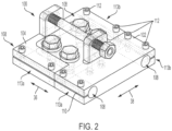
FIG. 2 is a perspective view of the shifter adjustment apparatus ofFIG. 1 . -
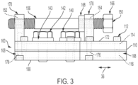
FIG. 3 is a side view of the shifter adjustment apparatus ofFIG. 1 . -
FIG. 4 is a rear view of the shifter adjustment apparatus ofFIG. 1 . -
FIG. 5 is a top view of the shifter adjustment apparatus ofFIG. 1 . -
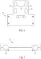
FIG. 6 is a top view of a first body of the shifter adjustment apparatus ofFIG. 1 . -
FIG. 7 is a front view of the first body of the shifter adjustment apparatus ofFIG. 1 . -
FIG. 8 is a top view of a second body of the shifter adjustment apparatus ofFIG. 1 . -
FIG. 9 is a rear view of the second body of the shifter adjustment apparatus ofFIG. 1 . -
FIG. 10 is a side view of an elongate rod of the shifter adjustment apparatus ofFIG. 1 . -
FIG. 11 is a perspective view of a portion of a needle bar shifter assembly having the shifter adjustment apparatus ofFIG. 1 . -
FIG. 12 is a perspective view of another portion of the needle bar shifter assembly having the shifter adjustment apparatus. -
FIG. 13 is a front view of a portion of the needle bar shifter assembly. -
FIG. 14 is an underside view of the needle bar shifter assembly, showing the shifter adjustment apparatus. - The present invention now will be described more fully hereinafter with reference to the accompanying drawings, in which some, but not all embodiments of the invention are shown. Indeed, this invention may be embodied in many different forms and should not be construed as limited to the embodiments set forth herein; rather, these embodiments are provided so that this disclosure will satisfy applicable legal requirements. Like numbers refer to like elements throughout. It is to be understood that this invention is not limited to the particular methodology and protocols described, as such may vary. It is also to be understood that the terminology used herein is for the purpose of describing particular embodiments only, and is not intended to limit the scope of the present invention.
- Many modifications and other embodiments of the invention set forth herein will come to mind to one skilled in the art to which the invention pertains having the benefit of the teachings presented in the foregoing description and the associated drawings. Therefore, it is to be understood that the invention is not to be limited to the specific embodiments disclosed and that modifications and other embodiments are intended to be included within the scope of the appended claims. Although specific terms are employed herein, they are used in a generic and descriptive sense only and not for purposes of limitation.
- As used herein the singular forms "a," "an," and "the" include plural referents unless the context clearly dictates otherwise. For example, use of the term "a screw" can refer to one or more of such screws, and so forth.
- All technical and scientific terms used herein have the same meaning as commonly understood to one of ordinary skill in the art to which this invention belongs unless clearly indicated otherwise.
- Ranges can be expressed herein as from "about" one particular value, and/or to "about" another particular value. When such a range is expressed, another aspect includes from the one particular value and/or to the other particular value. Similarly, when values are expressed as approximations, by use of the antecedent "about," it will be understood that the particular value forms another aspect. It will be further understood that the endpoints of each of the ranges are significant both in relation to the other endpoint, and independently of the other endpoint. Optionally, in some aspects, when values are approximated by use of the antecedent "about," it is contemplated that values within up to 15%, up to 10%, up to 5%, or up to 1% (above or below) of the particularly stated value can be included within the scope of those aspects. Similarly, in some optional aspects, when values are approximated by use of the terms "substantially" or "generally," it is contemplated that values within up to 15%, up to 10%, up to 5%, or up to 1% (above or below) of the particular value can be included within the scope of those aspects. When used with respect to an identified property or circumstance, "substantially" or "generally" can refer to a degree of deviation that is sufficiently small so as to not measurably detract from the identified property or circumstance, and the exact degree of deviation allowable may in some cases depend on the specific context.
- As used herein, the terms "optional" or "optionally" mean that the subsequently described event or circumstance may or may not occur, and that the description includes instances where said event or circumstance occurs and instances where it does not.
- As used herein, the term "at least one of" is intended to be synonymous with "one or more of." For example, "at least one of A, B and C" explicitly includes only A, only B, only C, and combinations of each.
- The word "or" as used herein means any one member of a particular list and also includes any combination of members of that list.
- It is to be understood that unless otherwise expressly stated, it is in no way intended that any method set forth herein be construed as requiring that its steps be performed in a specific order. Accordingly, where a method claim does not actually recite an order to be followed by its steps or it is not otherwise specifically stated in the claims or descriptions that the steps are to be limited to a specific order, it is in no way intended that an order be inferred, in any respect. This holds for any possible non-express basis for interpretation, including: matters of logic with respect to arrangement of steps or operational flow; plain meaning derived from grammatical organization or punctuation; and the number or type of aspects described in the specification.
- The following description supplies specific details in order to provide a thorough understanding. Nevertheless, the skilled artisan would understand that the apparatus, system, and associated methods of using the apparatus can be implemented and used without employing these specific details.
- Disclosed herein, in various aspects and with reference to
FIGS. 1 -14 is ashifter adjustment assembly 100 in combination with with a needle bar shifter assembly 10 (referred to herein as a "shifter"). Theshifter 10 comprises afirst shaft segment 12 having afirst end 14 and an opposingsecond end 16, asecond shaft segment 18 having afirst end 20 and an opposing second end 22, athird shaft segment 24 having afirst end 26 and an opposingsecond end 28, and afourth shaft segment 30 having afirst end 32 and an opposingsecond end 34. The first and second shaft segments are aligned and spaced apart in alongitudinal dimension 36, and thefirst end 14 of thefirst segment 12 faces thefirst end 20 of thesecond shaft segment 18. The third and fourth shaft segments is aligned and spaced apart in thelongitudinal dimension 36, and thefirst end 26 of thethird segment 24 faces thefirst end 32 of thefourth shaft segment 30. The first and second shaft segments are offset from the third and fourth shaft segments in a transverse dimension 38 that is perpendicular to thelongitudinal dimension 36. Optionally, the transverse dimension 38 can be horizontal. - As further explained below, it is contemplated that the disclosed shifter adjuster assemblies can permit faster, safer, and more precise tensioning adjustments in comparison to conventional methods. More particularly, the disclosed shifter adjuster assemblies can be located under the head of the tufting machine, making the location of adjustment easily and safely accessible without the need for entering a guarded area or using tools that cause damage to the shifter shaft. Optionally, the disclosed shifter adjuster assemblies can make use of fine threads that permit more precise tensioning adjustment.
- Referring also to
FIGS. 1 and2 , theshifter adjustment assembly 100 comprises afirst body 102 coupled to thefirst end 14 of thefirst shaft segment 12 and thefirst end 26 of thethird shaft segment 24. Theshifter adjustment assembly 100 further comprises asecond body 104 coupled to thefirst end 14 of thesecond shaft segment 12 and thefirst end 32 of thefourth shaft segment 30. For example, each of thefirst body 102 andsecond body 104 can define first and second through-bores 108 on opposing sides. Each of the first body and thesecond body 104 can have opposing first andsecond sides slit 110 can extend inwardly from a respective side (e.g., the first orsecond side 113a,b) of the respective body to a respective through-bore 108. One or more fasteners 112 (e.g., screws) can extend through aclearance hole 114 on a first (e.g., upper) side of theslit 110 and engage a threadedhole 116 on an opposing second (e.g., lower) side of theslit 110. In this way, tightening thefasteners 112 in the threaded hole can compress the body to close the slit, thereby decreasing the inner diameter of the throughbore 108 and frictionally engaging the respective shaft segment. - Referring to
FIGS. 1-2 and6-9 , thefirst body 102 andsecond body 104 are slidingly coupled so that movement between thefirst body 102 and thesecond body 104 in the transverse dimension 38 is restricted, but movement between thefirst body 102 and thesecond body 104 in thelongitudinal dimension 36 is permitted. For example, thefirst body 102 can define atongue 120 that can have a first longitudinally extendingouter edge 122 and a second longitudinally extendingouter edge 124 that is spaced from the first longitudinally extendingouter edge 122 in the transverse dimension 38. Thesecond body 104 can define agroove 126 having a first longitudinally extendinginner edge 128 and a second longitudinally extendinginner edge 130. Thetongue 120 can be receivable into the groove with a small clearance in the transverse dimension between thegroove 126 and thetongue 120 to inhibit transverse movement greater than the small clearance between the tongue and the groove. The firstouter edge 122 of thetongue 120 can slidingly engage the firstinner edge 128 of thegroove 126, and the secondouter edge 124 of thetongue 120 can slidingly engage the secondinner edge 130 of the groove. Thus, the firstinner edge 128 of thegroove 126 can restrict the movement of the tongue in a first direction relative to the transverse dimension, and the secondinner edge 130 of thegroove 126 can restrict the movement of the tongue in an opposing second direction relative to the transverse dimension, yet the first and second inner edges can guide the longitudinal movement of thetongue 120, and thus, thefirst body 102. - It is further contemplated that many alternative structures known to those skilled in the art can slidingly couple the first body to the second body, such as, for example, a dowel rod that is fixedly coupled to the first body and slidably receivable within a bore of the second body.
- Referring to
FIGS. 1-2 , acoupling 140 between thefirst body 102 and thesecond body 104 can secure the position of the first body with respect to the second body. For example, in some aspects, thecoupling 140 can comprise one or more fasteners 142 (e.g., screws or bolts) and, optionally,washers 143. In some optional aspects, thetongue 120 of thefirst body 102 can define one ormore slots 144 that are elongate in thelongitudinal dimension 36. Thesecond body 104 can define respective holes 146 (optionally, threaded holes) that are aligned in the transverse dimension withrespective slots 144 along a portion of a longitudinal travel of thefirst body 102 relative to thesecond body 104. In some aspects, thefasteners 142 can threadedly engage theholes 146. In further aspects (not shown), thefasteners 142 can be bolts that are bolted through theholes 146 into correspond nuts. When thefasteners 142 are loosened, thefirst body 102 can slide relative to thesecond body 104 along the longitudinal dimension, optionally limited by the length of the slots in the longitudinal dimension. When thefasteners 142 are tightened down, thefirst body 102 can be held in a fixed position with respect to the second body. - Referring to
FIGs. 1-3 , in some aspects, theshifter adjustment assembly 100 can comprise anadjustment device 150. In some aspects, the first body can define a first through-hole 152 that extends through the first body in the longitudinal dimension. The first through-hole 152 can define one at least one right-handed thread. Thesecond body 104 can comprise a second through-hole 154. The second through-hole 154 can define at least one left-handed thread. Anelongate rod 156 can have a length, afirst end 158, and an opposingsecond end 160. Theelongate rod 156 can define right-handed thread(s) 162 on the first end and extending along a portion of the length of theelongate rod 156. Theelongate rod 156 can define left-handed thread(s) 164 on thesecond end 160 and extending along a portion of the length of theelongate rod 156. The elongate rod can be threadedly coupled to, and extend between, thefirst body 102 and thesecond body 104. The right-handed thread(s) 162 of theelongate rod 156 can be threaded into the first throughhole 152 of the first body, and the left-handed thread(s) 164 of the elongate rod can be threaded into thesecond hole 154 of the second body. - Rotation of the elongate rod in a first direction can cause the first body to move away from the second body in the longitudinal dimension, and rotation of the elongate rod in a second direction that is opposite the first direction can cause the first body to move toward the second body. Optionally, the elongate rod can define one or more gripping features, such as, for example, a
hexagonal head 166, to facilitate rotation of the elongate rod. For example, a nut can be threaded onto one of the ends of theelongate rod 156 and then attached thereto via weldment. Optionally, ajam nut 168 can be threaded onto one of the ends of the elongate rod. The jam nut can be tightened down against a face of the respective body of the first and second body that shares the same thread(s) as thejam nut 168 to inhibit further rotation of the elongate rod with respect to either of the first or second bodies. - It is contemplated that the spacing between the
first body 102 and thesecond body 104 can, in some circumstances, be critical. Accordingly, the clearance between the threads of the first through-hole 152 and the right-handed thread(s) 162, and the clearance between the thread(s) of the second through-hole 154 and the left-handed thread(s) 164 can be minimized so that no (or substantially no) longitudinal movement is allowed between the elongate rod and the first and second bodies. For example, the first through-hole 152 and the second through-hole 154 can define Unified Thread Class 3A threads, and the right- and left-handed thread(s) 162, 164 can define Unified Thread Class 2B threads. In further aspects, all of the threads can be Class 3A. In this way, the exact spacing between the first and second bodies can be selected. - In some optional aspects, the
first body 102 can comprise afirst portion 170 and asecond portion 172 that can be coupled to the first portion (e.g., via screws 176). The first portion can define the through-hole 152. Thefirst portion 170 of thefirst body 102 can extend perpendicularly or generally perpendicularly from thesecond portion 172, such as, for example, vertically upward from an upper face of thesecond portion 172. Likewise, thesecond body 104 can comprise afirst portion 178 and asecond portion 180 that is coupled to the first portion (e.g., via screws 176). Thefirst portion 178 of thefirst body 102 can extend perpendicularly or generally perpendicularly from thesecond portion 180, such as, for example, vertically upward from an upper face of thesecond portion 180. - Referring to
FIG. 1 , optionally, a linear position sensor 182 (e.g., a linear potentiometer) can be coupled between thefirst body 102 and thesecond body 104 so that their positions relative to each other in the longitudinal dimension can be known. For example, a first end of thelinear position sensor 182 can couple to thefirst body 102, and a second end of the linear position sensor can couple to thesecond body 104. Optionally, the linear position sensor can be a capacitive scale having a resolution of, for example, 0.0005 inches. The linear position sensor can be in communication with a computing device (e.g., desktop computer, laptop, smartphone, tablet, etc.), a small LED display, or other output device to convey its sensed position to an operator. - Although the specification and figures describe certain features on the
first body 102 and complementary features on thesecond body 104, it should be understood that the features can be reversed unless specifically stated in the claims. For example, it should be understood that, in some alternative aspects, the first body can define thegroove 126, and the second body can comprise thetongue 120. In further alternative aspects, thefirst body 102 can define the left-handed thread(s) 164, and thesecond body 104 can define the right-handed thread(s) 162. Thus any feature stated in the claims should not be limited to its association with the first body or the second body unless the claims specifically state so. - Conventionally, both of the original shafts of the shifter of the tufting machine extend along the longitudinal length of the tufting machine. Thus, to attach the
shifter adjustment assembly 100, it is contemplated that the shafts can be cut to provide the first, second, third, and fourth shafts segments. It is further contemplated that the original shafts can be removed and replaced with shorter segments (i.e., the first, second, third, and fourth shaft segments) that, when coupled to theshifter adjustment assembly 100, provide the same length, or substantially the same length, as the original shafts of the shifter assembly. The first and third shaft segments can be inserted into the respective through-bores 108 of the first body, and thefasteners 112 can be tightened down. Likewise, the second and fourth shaft segments can be inserted into the respective through-bores 108 of the second body, and thefasteners 112 can be tightened down. - To adjust the needle tension with the shifter adjustment assembly, an operator can first verify that the needles are in an up position and not crossing over any hooks of the tufting machine. It can be desirable for the bracket not to be under tension or compression during adjustment. The tufting machine can be locked out for safety.
- The
jam nut 168 can be loosened from against the first or second body, and theslide fasteners 142 can be loosened to enable movement between the first and second body. Using a wrench, an operator can rotate the tension adjustment nut to adjust the position of the first body relative to the second body in the longitudinal dimension. For example, to increase tension on the needles, the first and second bodies can be moved toward each other. To decrease tension, the first and second bodies can be moved away from each other. Adjustment between the first and second bodies can shift the needle bar relative to the hook bar, thereby adjusting the positions of the needles with relative to their respective hooks. Optionally, the linear position sensor can output a readout, and the operator can select the relative position between the first and second body based on a desired readout from the linear position sensor. - Once the select position is achieved, the jam nut can be tightened against a respective body. The
fasteners 142 can be tightened down (e.g., to about 60 ft-lbs) to hold the first and second bodies in their relative positions. The tufting machine can be locked out to put the machine back in production. - Although the foregoing invention has been described in some detail by way of illustration and example for purposes of clarity of understanding, certain changes and modifications may be practiced within the scope of the appended claims.
Claims (14)
- An apparatus comprising:a needle bar shifter (10) of a tufting apparatus, the needle bar shifter having first (12), second (18), third (24), and fourth (30) shaft segments, each of the first (12), second (18), third (24), and fourth (30) shaft segments having respective first (14,20,26,32) and second (16,22,28,34) ends, the first (12) and second (18) shaft segments being aligned and spaced apart in a longitudinal dimension (36), the third (24) and fourth (30) shaft segments being aligned and spaced apart in the longitudinal dimension (36), the first ends (14,20) of the first (12) and second (18) shaft segments facing one another, the first ends (26,32) of the third (24) and fourth (30) shaft segments facing one another, the third (24) and fourth (30) shaft segments being offset from the first (12) and second (18) shaft segments in a transverse dimension (38) that is perpendicular to the longitudinal dimension; anda shifter adjustment assembly (100) configured to couple to the needle bar shifter (10), the shifter adjustment assembly (100) configured to cause adjustment of a position of a needle bar of the tufting apparatus relative to a hook bar of the tufting apparatus in order to maintain a select positioning of needles of the needle bar relative to respective hooks of the hook bar, the shifter adjustment assembly (100) comprising:a first body (102) that is configured to couple to the first ends (14,26) of the first (12) and third (24) shaft segments;a second body (104) that is configured to couple to the first ends (20,32) of the second (18) and fourth (30) shaft segments; anda coupling between the first body (102) and the second body (104), wherein the coupling is configured to releasably secure an axial position of the first body (102) with respect to the second body (104) along the longitudinal dimension (36),wherein the first body (102) and second body (104) define respective complementary surfaces that are configured for sliding engagement so that:movement between the first body (102) and the second body (104) in the transverse dimension (38) is restricted; andmovement between the first body (102) and the second body (104) in the longitudinal dimension (36) is permitted.
- The apparatus of claim 1, wherein the shifter adjustment assembly (100) further comprises an adjustment device (150) configured to move the first body (102) with respect to the second body (104) in the longitudinal dimension (36).
- The apparatus of claim 2, wherein the first body (102) defines a first through-hole (152) that extends through the first body (102) in the longitudinal dimension (36), wherein the second body (104) defines a second through-hole (154) that extends through the second body (104) in the longitudinal dimension (36), wherein the first through-hole (152) defines a right-hand thread, wherein the second through-hole (154) defines a left-hand thread, wherein the adjustment device (150) comprises an elongate rod (156) having a right-hand thread (162) on a first end (158) and a left-hand thread (164) on a second end (160) opposite the first end, wherein the right-hand thread (162) of the first end of the elongate rod is in engagement with the right hand thread of the first through-hole (152), and the left-hand thread (164) of the second end of the elongate rod is in engagement with the left-hand thread of the second through-hole (154).
- The apparatus of claim 3, further comprising a hexagonal head (166) coupled to the elongate rod (156).
- The apparatus of claim 3, wherein the adjustment device (150) further comprises a jam nut (168) that is threadedly movable on the elongate rod (156) and configured to bias against one of the first body (102) or the second body (104).
- The apparatus of claim 3, wherein the first body (102) comprises a first portion (170) and a second portion (172) that is coupled to the first portion, wherein the first portion (170) of the first body (102) defines the first through-hole (152) that defines the right-hand thread, wherein the second body (104) comprises a first portion (178) and a second portion (180) that is coupled to the first portion, wherein the first portion (178) of the second body (104) defines the second through-hole (154) that defines the left-hand thread.
- The apparatus of claim 1:wherein the first body (102) defines a first longitudinally extending through-bore (108) for receiving the first shaft segment (12),wherein the first body (102) defines a second longitudinally extending through-bore (108) for receiving the third shaft segment (24),wherein the second body (104) defines a first longitudinally extending through-bore (108) for receiving the second shaft segment (18), andwherein the second body (104) defines a second longitudinally extending through-bore (108) for receiving the fourth shaft segment (30).
- The apparatus of claim 1, wherein the first body (102) defines one of a tongue (120) or a groove (126), and the second body (104) defines the other of the tongue (120) and the groove (126), wherein the tongue (120) is receivable into the groove (126) with a clearance in the transverse dimension (38) between the groove (126) and the tongue (120) that inhibits transverse movement between the tongue (120) and the groove (126).
- The apparatus of claim 1, further comprising a linear position sensor (182) that is configured to detect at least one of a distance or a change in distance between the first body (102) and the second body (104) relative to the longitudinal dimension (36).
- A method of coupling a shifter adjustment assembly (100) of the apparatus of any one of the preceding claims to the needle bar shifter (10), the needle bar shifter (10) being a component of a tufting machine having a longitudinal dimension (36) that is perpendicular to a transverse dimension (38), the needle bar shifter (10) having a first end and a second end, the shifter comprising a first continuous shaft that extends between the first and second ends of the shifter and a second continuous shaft that extends between the first and second ends of the shifter, the method comprising:modifying or replacing the first continuous shaft of the needle bar shifter (10) to provide a first shaft segment (12) and a second shaft segment (18);modifying or replacing the second continuous shaft of the needle bar shifter (10) to provide a third shaft segment (24) and a fourth shaft segment (30); andcoupling the shifter adjustment assembly (100) to the first (12), second (18), third (24), and fourth (30) shaft segments.
- The method of claim 10, wherein the first continuous shaft is removed and replaced with the first shaft segment (12) and the second shaft segment (18), and wherein the second continuous shaft is removed and replaced with the third shaft segment (24) and the fourth shaft segment (30).
- The method of claim 10, wherein the first continuous shaft is cut to produce the first shaft segment (12) and the second shaft segment (18), and wherein the second continuous shaft is cut to produce the third shaft segment (24) and the fourth shaft segment (30).
- A tufting apparatus having a longitudinal dimension (36) and a transverse dimension (38), the tufting apparatus comprising:the apparatus of any one of claims 1-9;a needle bar comprising a plurality of needles; anda hook bar comprising a plurality of hooks.
- A method of using an apparatus as in any one of claims 1-9, wherein the shifter adjustment assembly (100) comprises an adjustment device (150) configured to move the first body (102) with respect to the second body (104) in the longitudinal dimension (36), the method comprising:adjusting the position of the first body (102) with respect to the second body (104); andsecuring the position of the first body (102) with respect to the second body (104).
Applications Claiming Priority (2)
| Application Number | Priority Date | Filing Date | Title |
|---|---|---|---|
| US202063015849P | 2020-04-27 | 2020-04-27 | |
| PCT/US2021/029392 WO2021222244A1 (en) | 2020-04-27 | 2021-04-27 | Needle bar tensioning apparatus |
Publications (4)
| Publication Number | Publication Date |
|---|---|
| EP4143374A1 EP4143374A1 (en) | 2023-03-08 |
| EP4143374A4 EP4143374A4 (en) | 2024-04-10 |
| EP4143374C0 EP4143374C0 (en) | 2025-06-04 |
| EP4143374B1 true EP4143374B1 (en) | 2025-06-04 |
Family
ID=78221942
Family Applications (1)
| Application Number | Title | Priority Date | Filing Date |
|---|---|---|---|
| EP21796435.2A Active EP4143374B1 (en) | 2020-04-27 | 2021-04-27 | Needle bar tensioning apparatus |
Country Status (8)
| Country | Link |
|---|---|
| US (1) | US11828011B2 (en) |
| EP (1) | EP4143374B1 (en) |
| CN (1) | CN115485427B (en) |
| AU (1) | AU2021264471A1 (en) |
| CA (1) | CA3176698A1 (en) |
| ES (1) | ES3036601T3 (en) |
| MX (1) | MX2022013487A (en) |
| WO (1) | WO2021222244A1 (en) |
Family Cites Families (11)
| Publication number | Priority date | Publication date | Assignee | Title |
|---|---|---|---|---|
| US3026830A (en) * | 1958-10-03 | 1962-03-27 | Cabin Crafts Inc | Tufting machine and method for producing multi-color designs in carpeting and the like |
| US3964407A (en) * | 1976-01-12 | 1976-06-22 | The Singer Company | Shiftable needle plate |
| US4392440A (en) * | 1981-04-13 | 1983-07-12 | Spencer Wright Industries, Inc. | Multi-stitch cam needle bar shifter for tufting machines |
| US4465001A (en) * | 1983-03-30 | 1984-08-14 | Spencer Wright Industries, Inc. | Tufting machine needle bar shifting apparatus |
| US4501212A (en) * | 1983-11-14 | 1985-02-26 | Spencer Wright Industries, Inc. | Tufting machines |
| US4662291A (en) * | 1986-07-18 | 1987-05-05 | Spencer Wright Industries, Inc. | Tufting machine sliding needle bar support |
| US5979344A (en) | 1997-01-31 | 1999-11-09 | Card-Monroe Corp. | Tufting machine with precision drive system |
| US7836836B2 (en) * | 2007-03-29 | 2010-11-23 | Brewer Stephanie | Self-adjusting cam follower bracket for tufting machine |
| US9545745B1 (en) * | 2010-11-23 | 2017-01-17 | Allied Dies, Inc. | Lip adjustment system |
| EP3004446B1 (en) * | 2013-05-29 | 2018-06-27 | Card-Monroe Corporation | Tufting machine drive system |
| US10156035B2 (en) * | 2017-03-15 | 2018-12-18 | Card-Monroe Corp. | Shift mechanism for a tufting machine |
-
2021
- 2021-04-27 CA CA3176698A patent/CA3176698A1/en active Pending
- 2021-04-27 US US17/241,674 patent/US11828011B2/en active Active
- 2021-04-27 AU AU2021264471A patent/AU2021264471A1/en active Pending
- 2021-04-27 MX MX2022013487A patent/MX2022013487A/en unknown
- 2021-04-27 WO PCT/US2021/029392 patent/WO2021222244A1/en not_active Ceased
- 2021-04-27 EP EP21796435.2A patent/EP4143374B1/en active Active
- 2021-04-27 ES ES21796435T patent/ES3036601T3/en active Active
- 2021-04-27 CN CN202180033444.3A patent/CN115485427B/en active Active
Also Published As
| Publication number | Publication date |
|---|---|
| CN115485427B (en) | 2025-12-26 |
| MX2022013487A (en) | 2023-01-05 |
| ES3036601T3 (en) | 2025-09-22 |
| US11828011B2 (en) | 2023-11-28 |
| AU2021264471A1 (en) | 2022-12-08 |
| CA3176698A1 (en) | 2021-11-04 |
| EP4143374A4 (en) | 2024-04-10 |
| CN115485427A (en) | 2022-12-16 |
| WO2021222244A1 (en) | 2021-11-04 |
| EP4143374C0 (en) | 2025-06-04 |
| EP4143374A1 (en) | 2023-03-08 |
| US20210332517A1 (en) | 2021-10-28 |
Similar Documents
| Publication | Publication Date | Title |
|---|---|---|
| DE69807019T2 (en) | Numerical control device and tool device with a numerical control device | |
| DE102016014155B4 (en) | Combined system with machine tool and robot | |
| DE602005005253T2 (en) | Machine tool and method for calculating the mounting position of a balance weight in the machine tool | |
| DE212020000162U1 (en) | Steel tape winding device with adjustable distance | |
| EP3241937B1 (en) | Sewing machine with an apparatus for manually exchanging a transporter | |
| HK82997A (en) | Clamping bar for use in a clamping device for workpieces destined to be processed on a machine-tool | |
| DE102012209836B4 (en) | Thread cutting device for rigid or synchronous thread cutting | |
| EP3969394A1 (en) | Transport system and transport method | |
| DE69133239T2 (en) | Machine for cutting single crystal ingots in wafers using an internal hole saw | |
| US11828011B2 (en) | Needle bar tensioning apparatus | |
| EP3658327A1 (en) | Roller burnishing tool | |
| EP3093079B1 (en) | Intake device for forming machine | |
| EP0268622A1 (en) | Process, measuring apparatus, precisely settable tool-holder with compensating device for process integrated quality insurance in cutting machine-tools | |
| EP3542962B1 (en) | System for assisting in the clamping of a workpiece | |
| DE102020108486B4 (en) | MACHINE TOOL, MACHINING SYSTEM AND ADDITIONAL TABLE UNIT | |
| DE102020203471B4 (en) | MACHINE TOOL AND MACHINING SYSTEM | |
| DE102021124955B3 (en) | Guide rail, method of adjustment therefor and roller guide | |
| US6368031B1 (en) | Axial feed apparatus having an adjustable feed stop and associated method | |
| EP1815943A1 (en) | Method and apparatus for honing bore holes. | |
| DE102015011112B4 (en) | Control device of an injection molding machine with a function of adjusting the balance of the bars, and control method of the injection molding machine | |
| DE3831436A1 (en) | WORKPIECE GRIPPERS AND HOLDERS | |
| DE102024130617A1 (en) | Cutting device for cutting flat material | |
| US20230166341A1 (en) | Adjustment unit for a guide bar on a machining tool, and machining tool | |
| DE102017121272A1 (en) | Finishing module for a machine tool and machining process | |
| US20150075339A1 (en) | Stock Puller |
Legal Events
| Date | Code | Title | Description |
|---|---|---|---|
| STAA | Information on the status of an ep patent application or granted ep patent |
Free format text: STATUS: THE INTERNATIONAL PUBLICATION HAS BEEN MADE |
|
| PUAI | Public reference made under article 153(3) epc to a published international application that has entered the european phase |
Free format text: ORIGINAL CODE: 0009012 |
|
| STAA | Information on the status of an ep patent application or granted ep patent |
Free format text: STATUS: REQUEST FOR EXAMINATION WAS MADE |
|
| 17P | Request for examination filed |
Effective date: 20221102 |
|
| AK | Designated contracting states |
Kind code of ref document: A1 Designated state(s): AL AT BE BG CH CY CZ DE DK EE ES FI FR GB GR HR HU IE IS IT LI LT LU LV MC MK MT NL NO PL PT RO RS SE SI SK SM TR |
|
| DAV | Request for validation of the european patent (deleted) | ||
| DAX | Request for extension of the european patent (deleted) | ||
| A4 | Supplementary search report drawn up and despatched |
Effective date: 20240307 |
|
| RIC1 | Information provided on ipc code assigned before grant |
Ipc: D05C 15/18 20060101AFI20240301BHEP |
|
| GRAP | Despatch of communication of intention to grant a patent |
Free format text: ORIGINAL CODE: EPIDOSNIGR1 |
|
| STAA | Information on the status of an ep patent application or granted ep patent |
Free format text: STATUS: GRANT OF PATENT IS INTENDED |
|
| INTG | Intention to grant announced |
Effective date: 20241211 |
|
| GRAS | Grant fee paid |
Free format text: ORIGINAL CODE: EPIDOSNIGR3 |
|
| GRAA | (expected) grant |
Free format text: ORIGINAL CODE: 0009210 |
|
| STAA | Information on the status of an ep patent application or granted ep patent |
Free format text: STATUS: THE PATENT HAS BEEN GRANTED |
|
| AK | Designated contracting states |
Kind code of ref document: B1 Designated state(s): AL AT BE BG CH CY CZ DE DK EE ES FI FR GB GR HR HU IE IS IT LI LT LU LV MC MK MT NL NO PL PT RO RS SE SI SK SM TR |
|
| REG | Reference to a national code |
Ref country code: GB Ref legal event code: FG4D |
|
| REG | Reference to a national code |
Ref country code: CH Ref legal event code: EP |
|
| REG | Reference to a national code |
Ref country code: DE Ref legal event code: R096 Ref document number: 602021031871 Country of ref document: DE |
|
| REG | Reference to a national code |
Ref country code: IE Ref legal event code: FG4D |
|
| U01 | Request for unitary effect filed |
Effective date: 20250625 |
|
| U07 | Unitary effect registered |
Designated state(s): AT BE BG DE DK EE FI FR IT LT LU LV MT NL PT RO SE SI Effective date: 20250701 |
|
| REG | Reference to a national code |
Ref country code: ES Ref legal event code: FG2A Ref document number: 3036601 Country of ref document: ES Kind code of ref document: T3 Effective date: 20250922 |
|
| PG25 | Lapsed in a contracting state [announced via postgrant information from national office to epo] |
Ref country code: NO Free format text: LAPSE BECAUSE OF FAILURE TO SUBMIT A TRANSLATION OF THE DESCRIPTION OR TO PAY THE FEE WITHIN THE PRESCRIBED TIME-LIMIT Effective date: 20250904 Ref country code: GR Free format text: LAPSE BECAUSE OF FAILURE TO SUBMIT A TRANSLATION OF THE DESCRIPTION OR TO PAY THE FEE WITHIN THE PRESCRIBED TIME-LIMIT Effective date: 20250905 |
|
| PG25 | Lapsed in a contracting state [announced via postgrant information from national office to epo] |
Ref country code: PL Free format text: LAPSE BECAUSE OF FAILURE TO SUBMIT A TRANSLATION OF THE DESCRIPTION OR TO PAY THE FEE WITHIN THE PRESCRIBED TIME-LIMIT Effective date: 20250604 |
|
| PG25 | Lapsed in a contracting state [announced via postgrant information from national office to epo] |
Ref country code: HR Free format text: LAPSE BECAUSE OF FAILURE TO SUBMIT A TRANSLATION OF THE DESCRIPTION OR TO PAY THE FEE WITHIN THE PRESCRIBED TIME-LIMIT Effective date: 20250604 |
|
| PG25 | Lapsed in a contracting state [announced via postgrant information from national office to epo] |
Ref country code: RS Free format text: LAPSE BECAUSE OF FAILURE TO SUBMIT A TRANSLATION OF THE DESCRIPTION OR TO PAY THE FEE WITHIN THE PRESCRIBED TIME-LIMIT Effective date: 20250904 |
|
| PG25 | Lapsed in a contracting state [announced via postgrant information from national office to epo] |
Ref country code: IS Free format text: LAPSE BECAUSE OF FAILURE TO SUBMIT A TRANSLATION OF THE DESCRIPTION OR TO PAY THE FEE WITHIN THE PRESCRIBED TIME-LIMIT Effective date: 20251004 |
|
| PG25 | Lapsed in a contracting state [announced via postgrant information from national office to epo] |
Ref country code: SM Free format text: LAPSE BECAUSE OF FAILURE TO SUBMIT A TRANSLATION OF THE DESCRIPTION OR TO PAY THE FEE WITHIN THE PRESCRIBED TIME-LIMIT Effective date: 20250604 |
|
| PG25 | Lapsed in a contracting state [announced via postgrant information from national office to epo] |
Ref country code: CZ Free format text: LAPSE BECAUSE OF FAILURE TO SUBMIT A TRANSLATION OF THE DESCRIPTION OR TO PAY THE FEE WITHIN THE PRESCRIBED TIME-LIMIT Effective date: 20250604 |
|
| PG25 | Lapsed in a contracting state [announced via postgrant information from national office to epo] |
Ref country code: SK Free format text: LAPSE BECAUSE OF FAILURE TO SUBMIT A TRANSLATION OF THE DESCRIPTION OR TO PAY THE FEE WITHIN THE PRESCRIBED TIME-LIMIT Effective date: 20250604 |
|
| PGFP | Annual fee paid to national office [announced via postgrant information from national office to epo] |
Ref country code: GB Payment date: 20260320 Year of fee payment: 6 |
|
| PLBE | No opposition filed within time limit |
Free format text: ORIGINAL CODE: 0009261 |
|
| STAA | Information on the status of an ep patent application or granted ep patent |
Free format text: STATUS: NO OPPOSITION FILED WITHIN TIME LIMIT |
|
| PGFP | Annual fee paid to national office [announced via postgrant information from national office to epo] |
Ref country code: IE Payment date: 20260311 Year of fee payment: 6 |
|
| REG | Reference to a national code |
Ref country code: CH Ref legal event code: L10 Free format text: ST27 STATUS EVENT CODE: U-0-0-L10-L00 (AS PROVIDED BY THE NATIONAL OFFICE) Effective date: 20260416 |
|
| PGFP | Annual fee paid to national office [announced via postgrant information from national office to epo] |
Ref country code: TR Payment date: 20260330 Year of fee payment: 6 |
|
| U20 | Renewal fee for the european patent with unitary effect paid |
Year of fee payment: 6 Effective date: 20260320 |
|
| 26N | No opposition filed |
Effective date: 20260305 |