EP4142653B1 - Modular reverse shoulder prosthesis - Google Patents
Modular reverse shoulder prosthesis Download PDFInfo
- Publication number
- EP4142653B1 EP4142653B1 EP22711244.8A EP22711244A EP4142653B1 EP 4142653 B1 EP4142653 B1 EP 4142653B1 EP 22711244 A EP22711244 A EP 22711244A EP 4142653 B1 EP4142653 B1 EP 4142653B1
- Authority
- EP
- European Patent Office
- Prior art keywords
- shoulder prosthesis
- reverse shoulder
- tray
- liner
- modular
- Prior art date
- Legal status (The legal status is an assumption and is not a legal conclusion. Google has not performed a legal analysis and makes no representation as to the accuracy of the status listed.)
- Active
Links
Images




Classifications
-
- A—HUMAN NECESSITIES
- A61—MEDICAL OR VETERINARY SCIENCE; HYGIENE
- A61F—FILTERS IMPLANTABLE INTO BLOOD VESSELS; PROSTHESES; DEVICES PROVIDING PATENCY TO, OR PREVENTING COLLAPSING OF, TUBULAR STRUCTURES OF THE BODY, e.g. STENTS; ORTHOPAEDIC, NURSING OR CONTRACEPTIVE DEVICES; FOMENTATION; TREATMENT OR PROTECTION OF EYES OR EARS; BANDAGES, DRESSINGS OR ABSORBENT PADS; FIRST-AID KITS
- A61F2/00—Filters implantable into blood vessels; Prostheses, i.e. artificial substitutes or replacements for parts of the body; Appliances for connecting them with the body; Devices providing patency to, or preventing collapsing of, tubular structures of the body, e.g. stents
- A61F2/02—Prostheses implantable into the body
- A61F2/30—Joints
- A61F2/40—Joints for shoulders
- A61F2/4003—Replacing only the epiphyseal or metaphyseal parts of the humerus, i.e. endoprosthesis not comprising an entire humeral shaft
-
- A—HUMAN NECESSITIES
- A61—MEDICAL OR VETERINARY SCIENCE; HYGIENE
- A61F—FILTERS IMPLANTABLE INTO BLOOD VESSELS; PROSTHESES; DEVICES PROVIDING PATENCY TO, OR PREVENTING COLLAPSING OF, TUBULAR STRUCTURES OF THE BODY, e.g. STENTS; ORTHOPAEDIC, NURSING OR CONTRACEPTIVE DEVICES; FOMENTATION; TREATMENT OR PROTECTION OF EYES OR EARS; BANDAGES, DRESSINGS OR ABSORBENT PADS; FIRST-AID KITS
- A61F2/00—Filters implantable into blood vessels; Prostheses, i.e. artificial substitutes or replacements for parts of the body; Appliances for connecting them with the body; Devices providing patency to, or preventing collapsing of, tubular structures of the body, e.g. stents
- A61F2/02—Prostheses implantable into the body
- A61F2/30—Joints
- A61F2/40—Joints for shoulders
-
- A—HUMAN NECESSITIES
- A61—MEDICAL OR VETERINARY SCIENCE; HYGIENE
- A61F—FILTERS IMPLANTABLE INTO BLOOD VESSELS; PROSTHESES; DEVICES PROVIDING PATENCY TO, OR PREVENTING COLLAPSING OF, TUBULAR STRUCTURES OF THE BODY, e.g. STENTS; ORTHOPAEDIC, NURSING OR CONTRACEPTIVE DEVICES; FOMENTATION; TREATMENT OR PROTECTION OF EYES OR EARS; BANDAGES, DRESSINGS OR ABSORBENT PADS; FIRST-AID KITS
- A61F2/00—Filters implantable into blood vessels; Prostheses, i.e. artificial substitutes or replacements for parts of the body; Appliances for connecting them with the body; Devices providing patency to, or preventing collapsing of, tubular structures of the body, e.g. stents
- A61F2/02—Prostheses implantable into the body
- A61F2/30—Joints
- A61F2002/30001—Additional features of subject-matter classified in A61F2/28, A61F2/30 and subgroups thereof
- A61F2002/30316—The prosthesis having different structural features at different locations within the same prosthesis; Connections between prosthetic parts; Special structural features of bone or joint prostheses not otherwise provided for
- A61F2002/30317—The prosthesis having different structural features at different locations within the same prosthesis
- A61F2002/30326—The prosthesis having different structural features at different locations within the same prosthesis differing in height or in length
-
- A—HUMAN NECESSITIES
- A61—MEDICAL OR VETERINARY SCIENCE; HYGIENE
- A61F—FILTERS IMPLANTABLE INTO BLOOD VESSELS; PROSTHESES; DEVICES PROVIDING PATENCY TO, OR PREVENTING COLLAPSING OF, TUBULAR STRUCTURES OF THE BODY, e.g. STENTS; ORTHOPAEDIC, NURSING OR CONTRACEPTIVE DEVICES; FOMENTATION; TREATMENT OR PROTECTION OF EYES OR EARS; BANDAGES, DRESSINGS OR ABSORBENT PADS; FIRST-AID KITS
- A61F2/00—Filters implantable into blood vessels; Prostheses, i.e. artificial substitutes or replacements for parts of the body; Appliances for connecting them with the body; Devices providing patency to, or preventing collapsing of, tubular structures of the body, e.g. stents
- A61F2/02—Prostheses implantable into the body
- A61F2/30—Joints
- A61F2002/30001—Additional features of subject-matter classified in A61F2/28, A61F2/30 and subgroups thereof
- A61F2002/30316—The prosthesis having different structural features at different locations within the same prosthesis; Connections between prosthetic parts; Special structural features of bone or joint prostheses not otherwise provided for
- A61F2002/30329—Connections or couplings between prosthetic parts, e.g. between modular parts; Connecting elements
- A61F2002/30331—Connections or couplings between prosthetic parts, e.g. between modular parts; Connecting elements made by longitudinally pushing a protrusion into a complementarily-shaped recess, e.g. held by friction fit
- A61F2002/30332—Conically- or frustoconically-shaped protrusion and recess
-
- A—HUMAN NECESSITIES
- A61—MEDICAL OR VETERINARY SCIENCE; HYGIENE
- A61F—FILTERS IMPLANTABLE INTO BLOOD VESSELS; PROSTHESES; DEVICES PROVIDING PATENCY TO, OR PREVENTING COLLAPSING OF, TUBULAR STRUCTURES OF THE BODY, e.g. STENTS; ORTHOPAEDIC, NURSING OR CONTRACEPTIVE DEVICES; FOMENTATION; TREATMENT OR PROTECTION OF EYES OR EARS; BANDAGES, DRESSINGS OR ABSORBENT PADS; FIRST-AID KITS
- A61F2/00—Filters implantable into blood vessels; Prostheses, i.e. artificial substitutes or replacements for parts of the body; Appliances for connecting them with the body; Devices providing patency to, or preventing collapsing of, tubular structures of the body, e.g. stents
- A61F2/02—Prostheses implantable into the body
- A61F2/30—Joints
- A61F2002/30001—Additional features of subject-matter classified in A61F2/28, A61F2/30 and subgroups thereof
- A61F2002/30316—The prosthesis having different structural features at different locations within the same prosthesis; Connections between prosthetic parts; Special structural features of bone or joint prostheses not otherwise provided for
- A61F2002/30329—Connections or couplings between prosthetic parts, e.g. between modular parts; Connecting elements
- A61F2002/30433—Connections or couplings between prosthetic parts, e.g. between modular parts; Connecting elements using additional screws, bolts, dowels, rivets or washers e.g. connecting screws
-
- A—HUMAN NECESSITIES
- A61—MEDICAL OR VETERINARY SCIENCE; HYGIENE
- A61F—FILTERS IMPLANTABLE INTO BLOOD VESSELS; PROSTHESES; DEVICES PROVIDING PATENCY TO, OR PREVENTING COLLAPSING OF, TUBULAR STRUCTURES OF THE BODY, e.g. STENTS; ORTHOPAEDIC, NURSING OR CONTRACEPTIVE DEVICES; FOMENTATION; TREATMENT OR PROTECTION OF EYES OR EARS; BANDAGES, DRESSINGS OR ABSORBENT PADS; FIRST-AID KITS
- A61F2/00—Filters implantable into blood vessels; Prostheses, i.e. artificial substitutes or replacements for parts of the body; Appliances for connecting them with the body; Devices providing patency to, or preventing collapsing of, tubular structures of the body, e.g. stents
- A61F2/02—Prostheses implantable into the body
- A61F2/30—Joints
- A61F2002/30001—Additional features of subject-matter classified in A61F2/28, A61F2/30 and subgroups thereof
- A61F2002/30316—The prosthesis having different structural features at different locations within the same prosthesis; Connections between prosthetic parts; Special structural features of bone or joint prostheses not otherwise provided for
- A61F2002/30535—Special structural features of bone or joint prostheses not otherwise provided for
- A61F2002/30604—Special structural features of bone or joint prostheses not otherwise provided for modular
-
- A—HUMAN NECESSITIES
- A61—MEDICAL OR VETERINARY SCIENCE; HYGIENE
- A61F—FILTERS IMPLANTABLE INTO BLOOD VESSELS; PROSTHESES; DEVICES PROVIDING PATENCY TO, OR PREVENTING COLLAPSING OF, TUBULAR STRUCTURES OF THE BODY, e.g. STENTS; ORTHOPAEDIC, NURSING OR CONTRACEPTIVE DEVICES; FOMENTATION; TREATMENT OR PROTECTION OF EYES OR EARS; BANDAGES, DRESSINGS OR ABSORBENT PADS; FIRST-AID KITS
- A61F2/00—Filters implantable into blood vessels; Prostheses, i.e. artificial substitutes or replacements for parts of the body; Appliances for connecting them with the body; Devices providing patency to, or preventing collapsing of, tubular structures of the body, e.g. stents
- A61F2/02—Prostheses implantable into the body
- A61F2/30—Joints
- A61F2/40—Joints for shoulders
- A61F2/4014—Humeral heads or necks; Connections of endoprosthetic heads or necks to endoprosthetic humeral shafts
- A61F2002/4018—Heads or epiphyseal parts of humerus
- A61F2002/4022—Heads or epiphyseal parts of humerus having a concave shape, e.g. hemispherical cups
-
- A—HUMAN NECESSITIES
- A61—MEDICAL OR VETERINARY SCIENCE; HYGIENE
- A61F—FILTERS IMPLANTABLE INTO BLOOD VESSELS; PROSTHESES; DEVICES PROVIDING PATENCY TO, OR PREVENTING COLLAPSING OF, TUBULAR STRUCTURES OF THE BODY, e.g. STENTS; ORTHOPAEDIC, NURSING OR CONTRACEPTIVE DEVICES; FOMENTATION; TREATMENT OR PROTECTION OF EYES OR EARS; BANDAGES, DRESSINGS OR ABSORBENT PADS; FIRST-AID KITS
- A61F2/00—Filters implantable into blood vessels; Prostheses, i.e. artificial substitutes or replacements for parts of the body; Appliances for connecting them with the body; Devices providing patency to, or preventing collapsing of, tubular structures of the body, e.g. stents
- A61F2/02—Prostheses implantable into the body
- A61F2/30—Joints
- A61F2/40—Joints for shoulders
- A61F2/4059—Humeral shafts
- A61F2002/4062—Proximal or metaphyseal parts of shafts
-
- A—HUMAN NECESSITIES
- A61—MEDICAL OR VETERINARY SCIENCE; HYGIENE
- A61F—FILTERS IMPLANTABLE INTO BLOOD VESSELS; PROSTHESES; DEVICES PROVIDING PATENCY TO, OR PREVENTING COLLAPSING OF, TUBULAR STRUCTURES OF THE BODY, e.g. STENTS; ORTHOPAEDIC, NURSING OR CONTRACEPTIVE DEVICES; FOMENTATION; TREATMENT OR PROTECTION OF EYES OR EARS; BANDAGES, DRESSINGS OR ABSORBENT PADS; FIRST-AID KITS
- A61F2310/00—Prostheses classified in A61F2/28 or A61F2/30 - A61F2/44 being constructed from or coated with a particular material
- A61F2310/00005—The prosthesis being constructed from a particular material
- A61F2310/00011—Metals or alloys
- A61F2310/00023—Titanium or titanium-based alloys, e.g. Ti-Ni alloys
Definitions
- the present invention relates to a modular shoulder prosthesis.
- the invention is particularly useful in surgeries for reverse shoulder prosthesis implantation and the following description is made with reference to this specific field of application, to simplify the exposition thereof.
- total shoulder prostheses provide a glenoidal prosthetic component and a humeral component, which articulate with each other.
- a first type of prosthesis intended to reproduce the natural anatomy of the gleno-humeral joint, provides a humeral component with a convex end that articulates on a concave end of a glenoidal component.
- a second type of prosthesis called "reverse” provides instead a convex glenoidal component that articulates on a concave humeral component, after resection of the humeral head; a reverse prosthesis is preferred in critical situations of rotator cuff instability.
- Document US 2014/236304 (A1 ) relates to a modular reverse and convertible shoulder prosthesis, that includes a distal stem, a reverse metaphysis, a reverse insert or liner that can be angled and a modular screw for coupling the reverse metaphysis with the distal stem.
- Document WO 2014/067961 (A1 ) relates to an implantation of a convertible reverse prosthesis including a humeral stem, a reverse tray and a reverse insert or liner made of polyethylene.
- the reverse insert is provided in alternatives having different inclination angles, for example 7.5°, 12.5° and 17.5°.
- a difficulty emerging in the prior art is due to the fact that, especially for modular reverse prostheses, the prosthesis size can involve an excessive tensioning of the surrounding tissues not only making it difficult to reduce the prosthesis at the surgical site but also leading to potential consequences in the short-medium term, among which for example a disadvantageous biomechanical configuration (suboptimal muscle lines of action, over-tensioned muscles, etc.) or bone fractures (acromial fractures due to the excessive tension).
- the design tends to be of the onlay type since it is difficult to maintain the lower point of the humeral concave joint surface in the area below the resection plane (metaphysis), since a connection system between the several modular components that leaves little space available in said area to house the concavity of the joint surface must in fact be provided, and moreover since there are technical limits relating to the minimum thicknesses of the articulating materials.
- An excessive onlay level in a reverse modular prosthesis can therefore worsen the mobility features (rotation, extension, adduction) and in general, as described above, worsen implant performances.
- a general object of the present invention is to provide to the surgeon a shoulder prosthesis that solves the drawbacks of the prior art.
- a further object of the present invention is to limit or reduce the onlay level in a liner of a reverse modular prosthesis.
- a further object of the present invention is to effectively allow different correction angles of a liner of a reverse modular prosthesis.
- a further object of the present invention is to improve the mobility features of a shoulder prosthesis.
- a further object of the present invention is to have a modular prosthesis stem having improved features.
- a further object of the present invention is to have a solution that can be applied to a convertible modular prosthesis, having possible anatomical prosthesis and reverse prosthesis configurations.
- the tray comprises a raised edge supporting a joint concave element of the liner.
- the raised edge has a reduced height on the side where the angled liner is thinned, thus forming an asymmetrical tray with respect to diametrically opposite portions.
- This device allows the liner to have a considerable reduction of the onlay level, but without affecting the liner minimum thicknesses and still allowing a sufficient support of the liner, especially on the full-height portions of the raised edge.
- a modular reverse shoulder prosthesis comprising: a stem comprising a tapered body and a first annular housing; a tray comprising a dome element for insertion into the first annular housing, and further comprising a second annular housing; a liner comprising an engaging element for at least partial insertion into the dome element, and further comprising a joint concave element configured for coupling with the second annular housing.
- the second annular housing of the tray comprises a raised edge configured to support the joint concave element.
- the raised edge defines an overall outline having a different development in height at least in diametrically opposite portions of said tray.
- a shoulder prosthesis system with a great modularity and versatility is thereby manufactured, that allows the implantation of different liners with different correction angles.
- the onlay level i.e., the distance between the bone resection plane and the lower point of the joint surface of the concave liner inserted into the tray, is reduced.
- the mobility features rotation, extension, adduction
- the general performances of the prosthesis are improved.
- the modular reverse shoulder prosthesis 100 further comprises a tray 120 comprising a dome element 121 for insertion into the first annular housing 112 of the stem 110.
- the tray 120 further comprises a second annular housing 122.
- the modular reverse shoulder prosthesis 100 comprises a liner 130 that includes an engaging element 131 configured for at least partial insertion into the dome element 121 of the tray 120.
- the liner 130 further comprises a joint concave element 132 configured for coupling with the second annular housing 122 of the tray 120.
- the joint concave element 132 is configured for a perimetrical coupling with the second annular housing 122 of the tray 120.
- the modular reverse shoulder prosthesis 100 allows a high modularity and versatility, being able to house different liners 130 having different correction angles, as it will be further described.
- the second annular housing 122 of the tray 120 comprises a raised edge 123 configured to support the joint concave element 132 of the liner 130.
- the tray 120 is made of a metal material, preferably of titanium or an alloy thereof.
- the tapered body 111 and the first annular housing 112 are formed as a single piece in the stem 110, also including the plurality of supports 113.
- the liner 130 is instead made of a plastic material, preferably polyethylene, in particular ultra-high molecular weight polyethylene (UHMWPE).
- polyethylene in particular ultra-high molecular weight polyethylene (UHMWPE).
- the tray 120 comprises the dome element 121 and the second annular housing 122.
- the second annular housing 122 comprises a raised edge 123, configured to support the joint concave element 132 of the liner 130 (not visible in figure 2 ).
- Figure 3 shows a lateral section of an exploded view of the modular reverse shoulder prosthesis 100, in which the already-described stem 110, tray 120 and liner 130 are represented.
- the tray 120 is assembled to the stem 110 by means of a conical coupling between the dome element 121 and the first annular housing 112, and preferably by means of a further coupling with a central safety screw 140.
- the liner 130 is assembled to the tray 120 by means of a snap engagement 150 acting between the engaging element 131 and an inner surface of the dome element 121.
- the liner 130 is assembled to the tray 120 by means of a further interference between the engaging element 131 and an inner surface of the dome element 121.
- the overall outline of the raised edge 123 comprises a first slanted portion 123a, configured for coupling with a respective slanted surface 133a (not visible in the figure section) of the joint concave element 132.
- the first portion 123a has a smaller development in height with respect to a second diametrically opposite portion 123b of the raised edge 123.
- the raised edge 123 defines an overall outline having a development in height, evaluated parallelly to the insertion axis 10, that is different at least in diametrically opposite portions 123a and 123b of the tray 120.
- the first portion 123a substantially includes a semicircular half of the raised edge 123.
- the overall outline comprises a planar portion 123b that is diametrically opposite the first portion 123a and having a greater development in height with respect thereto.
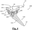
- Figure 4 shows a lateral section that is similar to figure 3 , of an assembled view of the modular reverse shoulder prosthesis 100.
- the dome element 121 is configured for insertion into the first annular housing 112 along the insertion axis 10 and the engaging element 131 as well is configured for insertion into the dome element 121 along the same insertion axis 10. It is also noted that the second annular housing 122 is arranged substantially perpendicular to the insertion axis 10.
- the joint concave element 132 of the liner 130 comprises an upper surface substantially lying on a correction plane 11.
- the correction plane 11 is slanted by a correction angle with respect to a plane that is perpendicular to the insertion axis 10.
- the tapered body 111 defines instead a stem primary axis 12 that is angled with respect to the insertion axis 10.
- the stem 110 is configured for implantation in a humeral bone end, while the liner 130 is configured to articulate with a respective glenoidal spherical element, or glenosphere, of a reverse shoulder prosthesis.
- the stem 110 is further configured to be adopted in a convertible prosthesis, and in this case the first annular housing 112 is further adapted to house prosthesis elements according to an anatomical configuration, in place of the already-described elements 120 and 130.
- Figure 5 shows a lateral view of the partial prosthesis assembly comprising the liner 130 and the tray 120.
- the raised edge 123 comprises a plurality of cutouts 124 configured for coupling with a respective plurality of outer protrusions 134 on the joint concave element 132, that are thus adapted to block a relative rotation between the tray 120 and the liner 130.
- Figure 6 shows the lateral section VI-VI of the assembly of figure 5 .
- the raised edge 123 defines an overall outline that, as can be seen in figure 6 , has a development in height that is different at least in diametrically opposite portions 123a and 123b of the tray 120.
- Figure 7 shows a detail of figure 6 , in which the coupling between the first portion 123a of the raised edge of the annular housing 122 and the respective surface 133a of the joint concave element 132 is better viewed.
- figures 8 and 9 show a comparison between the thicknesses of a liner in a solution according to the present invention, in figure 8 , and according to another example, in figure 9 . Localized magnifications in the portions identified by the dashed lines are also shown.
- a tray 120 and a liner 130 are shown, in which a raised edge of the tray 120 defines an overall outline that has a different development in height at least in diametrically opposite portions, thus being asymmetrical in height.
- a minimum thickness 80 of the liner 130 between the concave surface and the interface with the tray 120 is by way of example 3.9923 mm.
- a general tray and a general liner are shown, having a substantial diameter and size that are similar to those of the example of figure 8 .
- the raised edge of the tray defines an overall outline that has a same development in height in diametrically opposite portions, thus being symmetrical in height.
- the minimum thickness 90 of the liner between the concave surface and the interface with the tray is by way of example only 1.6187 mm, thus considerably smaller with respect to the minimum thickness 80 of the case of figure 8 .
- the onlay level can be reduced to the benefit of the prosthesis functionality and effectiveness.
- Figures 10 and 11 show respective sectional views on planes that are perpendicular to each other of a partial assembly composed of the already-described liner 130 and tray 120, and in addition composed of the already-described central safety screw 140 and snap engagement 150.
- Figure 12 shows a further embodiment of a tray 120' for a modular reverse shoulder prosthesis according to the present invention.
- the overall outline of the raised edge 123' comprises a first planar portion 123a', that still has a smaller development in height with respect to a second diametrically opposite portion 123b of the raised edge 123'.
- the overall outline of the raised edge 123' comprises a first planar portion 123a', configured for coupling with a respective planar surface (not visible in figure 12 ) of a joint concave element.
- the tray 120" has an annular housing 122" comprising an asymmetrical raised edge 123", that has a fully slanted configuration with respect to the only partially slanted configuration of the raised edge 123 of the embodiment already described above.
- the overall outline of the raised edge 123" comprises a first slanted portion 123a" that has a smaller development in height with respect to a second still slanted and diametrically opposite portion 123b".
- the modular reverse shoulder prosthesis 100' comprises the already-described stem 110, tray 120" and liner 130.
- the tray 120" is assembled to the stem 110 by means of a conical coupling between the dome element 121 and the first annular housing 112, and by means of a further coupling with a modular pin 140b.
- the modular pin 140b is preferably pre-assembled to the tray 120".
- the modular pin 140b allows the insertion of the components in the operating room to be facilitated and accelerated, and also the extraction to be accelerated in case of prosthesis revision, since it is sufficient to interpose a fork-like tool to arrange for the extraction of the tray 120" from the stem 110.
- the pin 140b offers a lower resistance to the axial extraction with respect to the screw 140, since only the conical coupling contributes to holding, it still ensures a suitable resistance to "lever-out" since in the shoulder there are basically compressive forces.
- the modular pin 140b is preferably pre-assembled to the tray 120.
- Figure 16 shows a lateral section that is similar to figure 15 , of an assembled view of the modular reverse shoulder prosthesis 100".
- the dome element 121 is configured for insertion into the first annular housing 112 of the stem 110 by means of the cooperation of the pin 140b.
- Figure 17 shows a three-dimensional view of an embodiment of the stem 110 for a modular reverse shoulder prosthesis according to the present invention, while figure 18 shows a front view of the stem 110 and figure 19 shows a lateral view of the stem 110.
- the stem 110 for a modular reverse shoulder prosthesis comprises a tapered body 111 and a first annular housing 112, configured to house other humeral components of the modular prosthesis, for example a tray 120 for the liner 130 as already described.
- the stem 110 is configured for implantation in a humeral bone end.
- the stem 110 is mainly configured for a modular reverse shoulder prosthesis, but it is also further configured for a convertible prosthesis, in which the first annular housing 112 is advantageously adapted to house modular anatomical prosthesis elements.
- the first annular housing 112 externally comprises a trabecular structure 201 configured to obtain a better fixation with the humeral bone.
- the first annular housing 112 allows the load to be transferred to the humerus, just below the resection, thus contributing to promote a better fixation of the metaphyseal type.
- the stem 110 further comprises a plurality of supports 113 connecting the tapered body 111 and the first annular housing 112, keeping them angled to each other.
- both the tapered body 111 and the first annular housing 112 and the plurality of supports 113 are made as a single piece in the stem 110.
- the plurality of supports 113 are configured for a fixation and stabilisation of the prosthesis implant.
- the plurality of supports 113 define a finned portion connecting the tapered body 111 and the first annular housing 112, tapering in turn in the area connecting with the tapered body 111.
- the plurality of supports 113 comprise a first medial support 211, two antero-posterior supports 212a and 212b and a lateral support 213.
- the plurality of supports 113 are configured to provide a rotational stability to the stem 110 as well as to stabilise the bending moment.
- the conformation of the antero-posterior supports 212a and 212b is curved according to the angle between the tapered body 111 and the first annular housing 112.
- the curved implantation direction of the stem 110 is thereby determined, that allows to follow the medial curve of the humerus in the insertion step, better adapting to the anatomy and thus facilitating the implantation step in the operating room.
- the undercut 20 of the stem 110 due to the angle between the tapered body 111 and the first annular housing 112, allows to avoid an excessive bone removal proximally due to an insertion along the diaphisary axis of the humerus.
- the two antero-posterior supports could be straight with respect to the stem primary axis, in order to allow an insertion of the implant in axis with the diaphisis in a more intuitive and reproducible manner.
- the gap created between the plurality of supports 113 allows a greater lateral area of the supports 211, 212a, 212b and 213 to be exposed to the bone, improving the implant bending and torsional stability. Moreover, advantageously, the gap created between the plurality of supports 113 reduces the weight and volume of the overall implant, and considerably decreases the amount of bone to be removed for the implantation; this reduces in turn the filling coefficient (given by the ratio between the volume of bone removed from the prosthesis and the volume of bone without the prosthesis) resulting in a minor invasiveness and a minor "stress-shielding" risk. Finally, the gap created between the plurality of supports 113 allows the distal part of the prosthesis to be accessed in case of a revision intervention.
- the distal portion of the stem 110, at the tapered body 111, has a substantially conical or frustoconical conformation with a circular section, that provides an additional stability to the implant, especially in the periods immediately after the surgery in which the bone is not still integrated in the first annular housing 112.
- the tapered body 111 comprises a polished end portion 202.
- the polished end portion 202 in addition to facilitating the insertion of the stem 110 during the surgical procedure, also allows a local osteointegration to be avoided, thus avoiding the transfer of loads distally and the consequent reabsorption of proximal bone due to "stress-shielding", and problems in the implant revision step, in which it would be otherwise difficult to access the distal portion of the tapered body 111 to detach any adherent bone without being excessively invasive.
- the stem 110 is symmetrical in order to be implanted both in right and left humeri. It has however a lateral average offset 21 between the stem primary axis 12 and a centre 22 of the first annular housing 112, configured to reproduce at best the offset anatomically existing in humeri.
Landscapes
- Health & Medical Sciences (AREA)
- Vascular Medicine (AREA)
- General Health & Medical Sciences (AREA)
- Oral & Maxillofacial Surgery (AREA)
- Transplantation (AREA)
- Engineering & Computer Science (AREA)
- Biomedical Technology (AREA)
- Cardiology (AREA)
- Life Sciences & Earth Sciences (AREA)
- Heart & Thoracic Surgery (AREA)
- Animal Behavior & Ethology (AREA)
- Orthopedic Medicine & Surgery (AREA)
- Public Health (AREA)
- Veterinary Medicine (AREA)
- Prostheses (AREA)
- Materials For Medical Uses (AREA)
Description
- The present invention relates to a modular shoulder prosthesis.
- The invention is particularly useful in surgeries for reverse shoulder prosthesis implantation and the following description is made with reference to this specific field of application, to simplify the exposition thereof.
- As it is well known, total shoulder prostheses provide a glenoidal prosthetic component and a humeral component, which articulate with each other.
- In clinical practice two types of total shoulder prostheses are used.
- A first type of prosthesis called "anatomical", intended to reproduce the natural anatomy of the gleno-humeral joint, provides a humeral component with a convex end that articulates on a concave end of a glenoidal component.
- A second type of prosthesis called "reverse" provides instead a convex glenoidal component that articulates on a concave humeral component, after resection of the humeral head; a reverse prosthesis is preferred in critical situations of rotator cuff instability.
- There are also "convertible" prostheses allowing an anatomical prosthesis to be converted into a reverse prosthesis without having to remove all the implant components, and even advantageously keeping the original bone anchorages.
- In general, for a replacement of a humeral head with a prosthesis, especially in case of reverse prostheses, different elements should be provided, that allow to obtain a desired overall inclination angle of the implant, by matching several stems of the implant with several inserts. It is thereby possible to obtain better joint mobility within the limits imposed by the resection surface and the general condition of the patient's anatomy.
- Document
US 2014/236304 (A1 ) relates to a modular reverse and convertible shoulder prosthesis, that includes a distal stem, a reverse metaphysis, a reverse insert or liner that can be angled and a modular screw for coupling the reverse metaphysis with the distal stem. - Document
WO 2014/067961 (A1 ) relates to an implantation of a convertible reverse prosthesis including a humeral stem, a reverse tray and a reverse insert or liner made of polyethylene. The reverse insert is provided in alternatives having different inclination angles, for example 7.5°, 12.5° and 17.5°. - Document
WO 2014/096912 (A1 ) relates to a shoulder prosthesis with a humeral stem having a proximal female seat for interchangeably housing adaptors for standard and reverse application. In this way, the shoulder prosthesis of the invention can be converted maintaining the tilting angle of the standard resection plane also in the reverse application. - A difficulty emerging in the prior art is due to the fact that, especially for modular reverse prostheses, the prosthesis size can involve an excessive tensioning of the surrounding tissues not only making it difficult to reduce the prosthesis at the surgical site but also leading to potential consequences in the short-medium term, among which for example a disadvantageous biomechanical configuration (suboptimal muscle lines of action, over-tensioned muscles, etc.) or bone fractures (acromial fractures due to the excessive tension). These size (and the relative consequences) are strictly connected to the position of the concave surface with respect to the humeral resection plane; specifically, the more a prosthetic design is of the "inlay" type, the more the lower point of the humeral concave joint surface is located below the resection plane; vice versa, the more a prosthetic design is of the "onlay" type, the more the lower point of the humeral concave joint surface is located above the resection plane. Especially in case of modular prostheses, the design tends to be of the onlay type since it is difficult to maintain the lower point of the humeral concave joint surface in the area below the resection plane (metaphysis), since a connection system between the several modular components that leaves little space available in said area to house the concavity of the joint surface must in fact be provided, and moreover since there are technical limits relating to the minimum thicknesses of the articulating materials.
- Moreover, the onlay level can be even more evident in case of liners having their own inclination angle, unlike radially symmetrical liners; in fact, in order to ensure minimum thicknesses that are compatible with the minimum mechanical strength requirements, a slanted liner requires the lower concavity point to be risen, hence increasing the onlay level.
- An excessive onlay level in a reverse modular prosthesis can therefore worsen the mobility features (rotation, extension, adduction) and in general, as described above, worsen implant performances.
- Meanwhile, it is not easy to reduce the onlay level not only because of the reduced spaces in the metaphysis but also because, by bringing the joint surface of the concave liner close to the resection plane, a thinning of the liner itself, that is typically made of ultra-high molecular weight polyethylene (UHMWPE), can be observed. An excessive thinning of the liner, although supported by the metal tray, causes a reduction of the mechanical strength and thus an overall worsening of the performances of the implant, that runs the risk of damaging when subjected to loads.
- A general object of the present invention is to provide to the surgeon a shoulder prosthesis that solves the drawbacks of the prior art.
- A further object of the present invention is to limit or reduce the onlay level in a liner of a reverse modular prosthesis.
- A further object of the present invention is to effectively allow different correction angles of a liner of a reverse modular prosthesis.
- A further object of the present invention is to improve the mobility features of a shoulder prosthesis.
- A further object of the present invention is to improve the mechanical strength of elements of a shoulder prosthesis, in particular of polyethylene liners.
- A further object of the present invention is to have a modular prosthesis stem having improved features.
- A further object of the present invention is to have a solution that can be applied to a convertible modular prosthesis, having possible anatomical prosthesis and reverse prosthesis configurations.
- The solution idea underlying the present invention is to provide a modular shoulder prosthesis comprising a stem, a tray inserted into the stem and a liner coupled with the tray, forming a reverse shoulder configuration.
- The tray comprises a raised edge supporting a joint concave element of the liner. The raised edge has a reduced height on the side where the angled liner is thinned, thus forming an asymmetrical tray with respect to diametrically opposite portions.
- This device allows the liner to have a considerable reduction of the onlay level, but without affecting the liner minimum thicknesses and still allowing a sufficient support of the liner, especially on the full-height portions of the raised edge.
- Based on this solution idea, a modular reverse shoulder prosthesis is provided, comprising: a stem comprising a tapered body and a first annular housing; a tray comprising a dome element for insertion into the first annular housing, and further comprising a second annular housing; a liner comprising an engaging element for at least partial insertion into the dome element, and further comprising a joint concave element configured for coupling with the second annular housing.
- The second annular housing of the tray comprises a raised edge configured to support the joint concave element. The raised edge defines an overall outline having a different development in height at least in diametrically opposite portions of said tray.
- A shoulder prosthesis system with a great modularity and versatility is thereby manufactured, that allows the implantation of different liners with different correction angles. For high correction angles too, the onlay level i.e., the distance between the bone resection plane and the lower point of the joint surface of the concave liner inserted into the tray, is reduced.
- Advantageously, due to the reduction of the onlay level the mobility features (rotation, extension, adduction) and the general performances of the prosthesis are improved.
- Meanwhile, advantageously, the overall outline of the tray edge, having a different or asymmetrical development in height, allows to keep sufficient thicknesses in each portion of the liner itself, improving the mechanical strength of the liner and of the overall prosthesis implant.
- Further features and advantages of the invention will become apparent from the following detailed description, given by way of non-limiting example, and from the claims that are an integral part of the present description.
-
-
Figure 1 shows a three-dimensional exploded view of an embodiment of a modular reverse shoulder prosthesis according to the present invention. -
Figure 2 shows a lateral sectional view of the tray offigure 1 . -
Figure 3 shows a lateral section of an exploded view of the modular reverse shoulder prosthesis offigure 1 . -
Figure 4 shows a lateral section that is similar tofigure 3 , of an assembled view of the modular reverse shoulder prosthesis offigure 1 . -
Figure 5 shows a lateral view of a liner and tray assembly offigure 1 . -
Figure 6 shows a lateral section offigure 5 . -
Figure 7 shows a detail offigure 6 . -
Figures 8 and 9 show a comparison between the thicknesses of the liner in a solution according to the present invention (fig. 8 ) and according to another example (fig. 9 ). -
figures 10 and 11 show sectional views on perpendicular planes of a liner and tray assembly offigure 1 . -
Figure 12 shows a further embodiment of a tray for a modular reverse shoulder prosthesis according to the present invention. -
Figure 13 shows a further embodiment of a tray for a modular reverse shoulder prosthesis according to the present invention. -
Figure 14 shows a three-dimensional exploded view of an alternative modular reverse shoulder prosthesis according to the present invention. -
Figure 15 shows a lateral section of an exploded view of a further alternative of a modular reverse shoulder prosthesis. -
Figure 16 shows a lateral section that is similar tofigure 15 , of an assembled view of the further alternative of a modular reverse shoulder prosthesis. -
Figure 17 shows a three-dimensional view of an embodiment of a stem for a modular reverse shoulder prosthesis according to the present invention. -
Figure 18 shows a front view of the stem offigure 17 . -
Figure 19 shows a lateral view of the stem offigure 17 . - In different figures, similar elements will be indicated with similar reference numbers.
- The technical drawings shown in the figures are to be intended as merely illustrative, not necessarily drawn to scale or having the same scale.
-
Figure 1 shows a three-dimensional exploded view of an embodiment of a modularreverse shoulder prosthesis 100 according to the present invention. - The modular
reverse shoulder prosthesis 100 comprises astem 110 comprising atapered body 111 and a firstannular housing 112. Preferably, thestem 110 further comprises a plurality ofsupports 113 connecting thetapered body 111 and the firstannular housing 112 to each other, keeping them angled to each other. As it will be thoroughly examined below, thestem 110 falls into the category "Short Stem" of humeral prostheses that is particularly advantageous due to the reduced invasiveness and the reduced bone volume occupied by the stem, allowing the "stress shielding" phenomenon to be mitigated. - The modular
reverse shoulder prosthesis 100 further comprises atray 120 comprising adome element 121 for insertion into the firstannular housing 112 of thestem 110. Thetray 120 further comprises a secondannular housing 122. - The modular
reverse shoulder prosthesis 100 comprises aliner 130 that includes anengaging element 131 configured for at least partial insertion into thedome element 121 of thetray 120. Theliner 130 further comprises a jointconcave element 132 configured for coupling with the secondannular housing 122 of thetray 120. In particular, the jointconcave element 132 is configured for a perimetrical coupling with the secondannular housing 122 of thetray 120. - In general, the modular
reverse shoulder prosthesis 100 allows a high modularity and versatility, being able to housedifferent liners 130 having different correction angles, as it will be further described. - Moreover, the second
annular housing 122 of thetray 120 comprises a raisededge 123 configured to support the jointconcave element 132 of theliner 130. - The
tray 120 is made of a metal material, preferably of titanium or an alloy thereof. In particular, thetapered body 111 and the firstannular housing 112 are formed as a single piece in thestem 110, also including the plurality ofsupports 113. - The
liner 130 is instead made of a plastic material, preferably polyethylene, in particular ultra-high molecular weight polyethylene (UHMWPE). -
Figure 2 shows a lateral sectional view of thetray 120. - As described, the
tray 120 comprises thedome element 121 and the secondannular housing 122. The secondannular housing 122 comprises a raisededge 123, configured to support the jointconcave element 132 of the liner 130 (not visible infigure 2 ). - The raised
edge 123 defines an overall outline that, as can be well seen infigure 2 , has a different development in height at least in diametricallyopposite portions tray 120. -
Figure 3 shows a lateral section of an exploded view of the modularreverse shoulder prosthesis 100, in which the already-describedstem 110,tray 120 andliner 130 are represented. - Specifically, the
tray 120 is assembled to thestem 110 by means of a conical coupling between thedome element 121 and the firstannular housing 112, and preferably by means of a further coupling with acentral safety screw 140. Theliner 130 is assembled to thetray 120 by means of asnap engagement 150 acting between theengaging element 131 and an inner surface of thedome element 121. Moreover, preferably, theliner 130 is assembled to thetray 120 by means of a further interference between theengaging element 131 and an inner surface of thedome element 121. - In this view of the modular
reverse shoulder prosthesis 100 it can be appreciated that the overall outline of the raisededge 123 comprises a first slantedportion 123a, configured for coupling with a respective slantedsurface 133a (not visible in the figure section) of the jointconcave element 132. Thefirst portion 123a has a smaller development in height with respect to a second diametricallyopposite portion 123b of the raisededge 123. - In particular, as it can be seen in
figure 3 , thedome element 121 is configured for insertion into the firstannular housing 112 along aninsertion axis 10, and theengaging element 131 is configured for insertion into thedome element 121 along thesame insertion axis 10. In the present description, when referring to "height" or "development in height" of the raised edge of thetray 120, a dimension of the raised edge evaluated along theinsertion axis 10 is to be meant. - In general, the raised
edge 123 defines an overall outline having a development in height, evaluated parallelly to theinsertion axis 10, that is different at least in diametricallyopposite portions tray 120. - Focusing on the
first portion 123a, it substantially includes a semicircular half of the raisededge 123. In the other semicircular half of the raisededge 123, the overall outline comprises aplanar portion 123b that is diametrically opposite thefirst portion 123a and having a greater development in height with respect thereto. -
Figure 4 shows a lateral section that is similar tofigure 3 , of an assembled view of the modularreverse shoulder prosthesis 100. - In this view, it is appreciated that in order to form the modular structure of the
prosthesis 100, thedome element 121 is configured for insertion into the firstannular housing 112 along theinsertion axis 10 and theengaging element 131 as well is configured for insertion into thedome element 121 along thesame insertion axis 10. It is also noted that the secondannular housing 122 is arranged substantially perpendicular to theinsertion axis 10. - The joint
concave element 132 of theliner 130 comprises an upper surface substantially lying on acorrection plane 11. Thecorrection plane 11 is slanted by a correction angle with respect to a plane that is perpendicular to theinsertion axis 10. Thetapered body 111 defines instead a stemprimary axis 12 that is angled with respect to theinsertion axis 10. - In general, the
stem 110 is configured for implantation in a humeral bone end, while theliner 130 is configured to articulate with a respective glenoidal spherical element, or glenosphere, of a reverse shoulder prosthesis. - In an alternative of the shoulder prosthesis, the
stem 110 is further configured to be adopted in a convertible prosthesis, and in this case the firstannular housing 112 is further adapted to house prosthesis elements according to an anatomical configuration, in place of the already-describedelements -
Figure 5 shows a lateral view of the partial prosthesis assembly comprising theliner 130 and thetray 120. - In this view it can be appreciated that the raised
edge 123 comprises a plurality ofcutouts 124 configured for coupling with a respective plurality ofouter protrusions 134 on the jointconcave element 132, that are thus adapted to block a relative rotation between thetray 120 and theliner 130. -
Figure 6 shows the lateral section VI-VI of the assembly offigure 5 . As already described, the raisededge 123 defines an overall outline that, as can be seen infigure 6 , has a development in height that is different at least in diametricallyopposite portions tray 120. - In fact, by reducing the height of the raised
edge 123, on theside 123a where theliner 130 has a smaller development in height due to the provided correction angle, thetray 120 is made asymmetrical in height. This modification allows theliner 130 to have a considerable reduction of the onlay level, without however affecting the minimum thicknesses of the jointconcave element 132, and still allowing a sufficient support of theliner 130 by means of thehighest portion 123b of theedge 123 of thetray 120. -
Figure 7 shows a detail offigure 6 , in which the coupling between thefirst portion 123a of the raised edge of theannular housing 122 and therespective surface 133a of the jointconcave element 132 is better viewed. - In order to clarify the effect of the present invention,
figures 8 and 9 show a comparison between the thicknesses of a liner in a solution according to the present invention, infigure 8 , and according to another example, infigure 9 . Localized magnifications in the portions identified by the dashed lines are also shown. - In
figure 8 atray 120 and aliner 130 are shown, in which a raised edge of thetray 120 defines an overall outline that has a different development in height at least in diametrically opposite portions, thus being asymmetrical in height. In this case, aminimum thickness 80 of theliner 130 between the concave surface and the interface with thetray 120 is by way of example 3.9923 mm. - In
figure 9 a general tray and a general liner are shown, having a substantial diameter and size that are similar to those of the example offigure 8 . However, in this case the raised edge of the tray defines an overall outline that has a same development in height in diametrically opposite portions, thus being symmetrical in height. In this case, theminimum thickness 90 of the liner between the concave surface and the interface with the tray is by way of example only 1.6187 mm, thus considerably smaller with respect to theminimum thickness 80 of the case offigure 8 . - It is thus evident that in the solution of the present invention, for the same onlay level and in the presence of a same correction angle of the liners, there is no thinning of the thickness of the liner itself, to the benefit of a mechanical strength.
- From another point of view, in the solution of the present invention for the same minimum thickness of the liner and thus reasonably keeping the mechanical strength properties of the liner, the onlay level can be reduced to the benefit of the prosthesis functionality and effectiveness.
-
Figures 10 and 11 show respective sectional views on planes that are perpendicular to each other of a partial assembly composed of the already-describedliner 130 andtray 120, and in addition composed of the already-describedcentral safety screw 140 and snapengagement 150. -
Figure 12 shows a further embodiment of a tray 120' for a modular reverse shoulder prosthesis according to the present invention. - In this alternative, the tray 120' has an annular housing 122' still comprising an asymmetrical raised edge 123', but with a planar and not slanted configuration as in the raised
edge 123 of the embodiment already described above, and that complies however with the minimum thicknesses of the liner associated therewith. - In detail, the overall outline of the raised edge 123' comprises a first
planar portion 123a', that still has a smaller development in height with respect to a second diametricallyopposite portion 123b of the raised edge 123'. In general, the overall outline of the raised edge 123' comprises a firstplanar portion 123a', configured for coupling with a respective planar surface (not visible infigure 12 ) of a joint concave element. - In this alternative with the asymmetrical raised edge 123' and the first
planar portion 123a', there is a greater minimum edge thickness while maintaining a same onlay level; this alternative is like a trade-off with respect to the previous exemplary embodiment and it takes thus the form of a liner with a smaller thickness with respect to the version of theangled liner 130. This trade-off is admissible as long as the minimum thicknesses required for the mechanical strength of the liner are complied with, thus limiting the correction angle of the liner. - It should also be considered that the rise of the raised edge 123' with respect to the raised
edge 123, proves to be beneficial from a liner containment and stability point of view. The asymmetrical and flat raised edge 123', with respect to the asymmetrical and angled one 123, adds some material in the tray 120' where there is a coupling by interference and removes some material where there is an urging bevel for the insertion of a liner. It can thus be said that the flat version of an asymmetrical tray 120' could have more usable surface for the coupling by interference with a liner, making the assembly thereof more stable.Figure 13 shows a sectional view of a further embodiment of atray 120" for a modular reverse shoulder prosthesis according to the present invention. - In this alternative, the
tray 120" has anannular housing 122" comprising an asymmetrical raisededge 123", that has a fully slanted configuration with respect to the only partially slanted configuration of the raisededge 123 of the embodiment already described above. - In detail, the overall outline of the raised
edge 123" comprises a first slantedportion 123a" that has a smaller development in height with respect to a second still slanted and diametricallyopposite portion 123b". - This alternative of the
tray 120" with a fully slanted raisededge 123" is also admissible, as long as the minimum thicknesses required for the mechanical strength of the liner are complied with. -
Figure 14 shows a three-dimensional exploded view of an alternative modular reverse shoulder prosthesis 100' according to the present invention. - The modular reverse shoulder prosthesis 100' comprises the already-described
stem 110,tray 120" andliner 130. - In this embodiment, the
tray 120" is assembled to thestem 110 by means of a conical coupling between thedome element 121 and the firstannular housing 112, and by means of a further coupling with amodular pin 140b. - The
modular pin 140b is preferably pre-assembled to thetray 120". With respect to the already-describedscrew system 140, themodular pin 140b allows the insertion of the components in the operating room to be facilitated and accelerated, and also the extraction to be accelerated in case of prosthesis revision, since it is sufficient to interpose a fork-like tool to arrange for the extraction of thetray 120" from thestem 110. Moreover, although thepin 140b offers a lower resistance to the axial extraction with respect to thescrew 140, since only the conical coupling contributes to holding, it still ensures a suitable resistance to "lever-out" since in the shoulder there are basically compressive forces. -
Figure 15 shows a lateral section of an exploded view of a further alternative of a modularreverse shoulder prosthesis 100", in which the already-describedstem 110,tray 120,liner 130 andmodular pin 140b are represented. - In this embodiment too, preferably, the
modular pin 140b is preferably pre-assembled to thetray 120. -
Figure 16 shows a lateral section that is similar tofigure 15 , of an assembled view of the modularreverse shoulder prosthesis 100". - In this view, it is appreciated that in order to form the modular structure of the
prosthesis 100", thedome element 121 is configured for insertion into the firstannular housing 112 of thestem 110 by means of the cooperation of thepin 140b. -
Figure 17 shows a three-dimensional view of an embodiment of thestem 110 for a modular reverse shoulder prosthesis according to the present invention, whilefigure 18 shows a front view of thestem 110 andfigure 19 shows a lateral view of thestem 110. - The
stem 110 for a modular reverse shoulder prosthesis comprises atapered body 111 and a firstannular housing 112, configured to house other humeral components of the modular prosthesis, for example atray 120 for theliner 130 as already described. - In the implantation of a shoulder prosthesis, the
stem 110 is configured for implantation in a humeral bone end. Thestem 110 is mainly configured for a modular reverse shoulder prosthesis, but it is also further configured for a convertible prosthesis, in which the firstannular housing 112 is advantageously adapted to house modular anatomical prosthesis elements. - Preferably, the first
annular housing 112 externally comprises atrabecular structure 201 configured to obtain a better fixation with the humeral bone. The firstannular housing 112 allows the load to be transferred to the humerus, just below the resection, thus contributing to promote a better fixation of the metaphyseal type. - The
stem 110 further comprises a plurality ofsupports 113 connecting thetapered body 111 and the firstannular housing 112, keeping them angled to each other. In particular, both thetapered body 111 and the firstannular housing 112 and the plurality ofsupports 113 are made as a single piece in thestem 110. - In general, the plurality of
supports 113 are configured for a fixation and stabilisation of the prosthesis implant. In greater detail, the plurality ofsupports 113 define a finned portion connecting thetapered body 111 and the firstannular housing 112, tapering in turn in the area connecting with thetapered body 111. In particular, the plurality ofsupports 113 comprise a firstmedial support 211, two antero-posterior supports lateral support 213. The plurality ofsupports 113 are configured to provide a rotational stability to thestem 110 as well as to stabilise the bending moment. - Preferably, the conformation of the antero-
posterior supports tapered body 111 and the firstannular housing 112. The curved implantation direction of thestem 110 is thereby determined, that allows to follow the medial curve of the humerus in the insertion step, better adapting to the anatomy and thus facilitating the implantation step in the operating room. - Moreover, the undercut 20 of the
stem 110, due to the angle between thetapered body 111 and the firstannular housing 112, allows to avoid an excessive bone removal proximally due to an insertion along the diaphisary axis of the humerus. - In an alternative, not represented, the two antero-posterior supports could be straight with respect to the stem primary axis, in order to allow an insertion of the implant in axis with the diaphisis in a more intuitive and reproducible manner.
- Advantageously, the gap created between the plurality of
supports 113 allows a greater lateral area of thesupports supports 113 reduces the weight and volume of the overall implant, and considerably decreases the amount of bone to be removed for the implantation; this reduces in turn the filling coefficient (given by the ratio between the volume of bone removed from the prosthesis and the volume of bone without the prosthesis) resulting in a minor invasiveness and a minor "stress-shielding" risk. Finally, the gap created between the plurality ofsupports 113 allows the distal part of the prosthesis to be accessed in case of a revision intervention. - The distal portion of the
stem 110, at thetapered body 111, has a substantially conical or frustoconical conformation with a circular section, that provides an additional stability to the implant, especially in the periods immediately after the surgery in which the bone is not still integrated in the firstannular housing 112. - More particularly, the substantially conical shape of the
stem 110 contributes to convert axial translations into circumferential forces, thus increasing the "press-fit" of the implant. - Preferably, the
tapered body 111 comprises apolished end portion 202. Thepolished end portion 202 in addition to facilitating the insertion of thestem 110 during the surgical procedure, also allows a local osteointegration to be avoided, thus avoiding the transfer of loads distally and the consequent reabsorption of proximal bone due to "stress-shielding", and problems in the implant revision step, in which it would be otherwise difficult to access the distal portion of thetapered body 111 to detach any adherent bone without being excessively invasive. - Finally, preferably, the
stem 110 is symmetrical in order to be implanted both in right and left humeri. It has however a lateral average offset 21 between the stemprimary axis 12 and acentre 22 of the firstannular housing 112, configured to reproduce at best the offset anatomically existing in humeri. - It should be noted that, since the
stem 110 is a modular component spaced apart from the above-describedtray 120 andliner 130, it could also be used in other alternatives of shoulder prostheses, both reverse and anatomical. - Moreover, it is clear that further implementations and modifications of the present invention will be possible for the person skilled in the art, in order to meet contingent needs.
- The above-described embodiments are therefore to be understood as provided for illustrative and non-limiting purposes.
Claims (15)
- Modular reverse shoulder prosthesis, comprising:- a stem (110) comprising a tapered body (111) and a first annular housing (112);- a tray (120) comprising a dome element (121) for insertion into said first annular housing (112), and further comprising a second annular housing (122);- a liner (130) comprising an engaging element (131) for at least partial insertion into said dome element (121), and further comprising a joint concave element (132) configured for coupling with said second annular housing (122);wherein said second annular housing (122) of said tray (120) comprises a raised edge (123) configured to support said joint concave element (132),characterised in that said raised edge (123) defines an overall outline having a development in height that is different at least in diametrically opposite portions (123a; 123b) of said tray (120).
- Modular reverse shoulder prosthesis according to claim 1, wherein said overall outline of said raised edge (123) comprises a first planar portion (123a'), configured for coupling with a respective planar surface of said joint concave element (132), said first planar portion (123a') having a smaller development in height with respect to a second diametrically opposite portion (123b) of said raised edge.
- Modular reverse shoulder prosthesis according to claim 1, wherein said overall outline of said raised edge (123) comprises a first slanted portion (123a; 123a"), configured for coupling with a respective slanted surface (133a) of said joint concave element (132), said first slanted portion (123a; 123a") having a smaller development in height with respect to a second diametrically opposite portion (123b; 123b") of said raised edge.
- Modular reverse shoulder prosthesis according to claim 2 or 3, wherein said first portion (123a) substantially includes a semicircular half of said raised edge (123).
- Modular reverse shoulder prosthesis according to any one of claims 1 to 4, wherein said overall outline of said raised edge (123) comprises a planar portion (123b) that is diametrically opposite said first portion (123a; 123a') and having a greater development in height with respect to said first portion (123; 123a').
- Modular reverse shoulder prosthesis according to any one of claims 1 to 5, wherein said raised edge (123) comprises a plurality of cutouts (124) configured for coupling with a respective plurality of outer protrusions (134) on said joint concave element (132), so as to block a relative rotation of said tray (120) and of said liner (130).
- Modular reverse shoulder prosthesis according to any one of claims 1 to 6, wherein said dome element (121) is configured for insertion into said first annular housing (112) along an insertion axis (10), and wherein said engaging element (131) is configured for insertion into said dome element (121) along said insertion axis (10), and wherein said second annular housing (122) is arranged substantially perpendicular to said insertion axis (10).
- Modular reverse shoulder prosthesis according to claim 7, wherein said joint concave element (132) of said liner (130) comprises an upper surface substantially lying on a correction plane (11), said correction plane (11) being slanted by a correction angle with respect to a plane that is perpendicular to said insertion axis (10).
- Modular reverse shoulder prosthesis according to any one of claims 1 to 8, wherein said tray (120) is assembled to said stem (110) by means of a conical coupling between said dome element (121) and said first annular housing (112), and preferably by means of a further coupling with a central safety screw (140) or a modular pin (140b).
- Modular reverse shoulder prosthesis according to any one of claims 1 to 9, wherein said liner (130) is assembled to said tray (120) by means of a snap engagement (150) between said engaging element (131) and an inner surface of said dome element (121), and preferably by means of a further interference between said engaging element (131) and said inner surface of said dome element (121).
- Modular reverse shoulder prosthesis according to any one of claims 1 to 10, wherein said tray (120) is made of a metal material, preferably a titanium alloy or comprising titanium, and wherein said liner (130) is made of a plastic material, preferably polyethylene.
- Modular reverse shoulder prosthesis according to any one of claims 1 to 11, wherein said first annular housing (112) externally comprises a trabecular structure (201).
- Modular reverse shoulder prosthesis according to any one of claims 1 to 12, wherein said stem (110) is configured for implantation in a humeral bone end, and wherein said liner (130) is configured to articulate with a respective glenoidal spherical element of a reverse shoulder prosthesis.
- Modular reverse shoulder prosthesis according to any one of claims 1 to 13, wherein said stem (110) is further configured for a convertible prosthesis, said first annular housing (112) being further adapted to house prosthesis elements according to an anatomical configuration.
- Modular reverse shoulder prosthesis according to any one of claims 1 to 14, wherein said tapered body (111) has a substantially conical or frustoconical conformation with a circular section, preferably said tapered body (111) comprising a polished end portion (202).
Applications Claiming Priority (2)
| Application Number | Priority Date | Filing Date | Title |
|---|---|---|---|
| IT102021000005858A IT202100005858A1 (en) | 2021-03-12 | 2021-03-12 | MODULAR REVERSE SHOULDER PROSTHESIS |
| PCT/EP2022/056089 WO2022189532A1 (en) | 2021-03-12 | 2022-03-09 | Modular reverse shoulder prosthesis |
Publications (2)
| Publication Number | Publication Date |
|---|---|
| EP4142653A1 EP4142653A1 (en) | 2023-03-08 |
| EP4142653B1 true EP4142653B1 (en) | 2025-04-16 |
Family
ID=76159742
Family Applications (1)
| Application Number | Title | Priority Date | Filing Date |
|---|---|---|---|
| EP22711244.8A Active EP4142653B1 (en) | 2021-03-12 | 2022-03-09 | Modular reverse shoulder prosthesis |
Country Status (9)
| Country | Link |
|---|---|
| US (2) | US12245946B2 (en) |
| EP (1) | EP4142653B1 (en) |
| JP (1) | JP2024512836A (en) |
| CN (1) | CN115867233A (en) |
| AU (1) | AU2022235411A1 (en) |
| BR (1) | BR112022025268A2 (en) |
| ES (1) | ES3025150T3 (en) |
| IT (1) | IT202100005858A1 (en) |
| WO (1) | WO2022189532A1 (en) |
Families Citing this family (3)
| Publication number | Priority date | Publication date | Assignee | Title |
|---|---|---|---|---|
| USD977643S1 (en) * | 2019-03-12 | 2023-02-07 | Shoulder Innovations, Inc. | Humeral stem implant |
| WO2023086853A1 (en) * | 2021-11-11 | 2023-05-19 | Arthrex, Inc. | Arthroplasty implant systems with stemless implants |
| WO2024258699A1 (en) * | 2023-06-13 | 2024-12-19 | Smith & Nephew, Inc. | Tapered protrusions on arthroplasty implant stem |
Family Cites Families (27)
| Publication number | Priority date | Publication date | Assignee | Title |
|---|---|---|---|---|
| US7682398B2 (en) * | 2000-03-14 | 2010-03-23 | Smith & Nephew, Inc. | Variable geometry rim surface acetabular shell liner |
| US6790234B1 (en) * | 2002-01-04 | 2004-09-14 | Frankle Mark A | Reverse shoulder prosthesis system |
| US6916342B2 (en) * | 2002-04-01 | 2005-07-12 | Smith & Nephew, Inc. | Liner assembly for prosthetic components |
| US8062376B2 (en) * | 2002-07-10 | 2011-11-22 | Biomet Manufacturing Corp. | Shoulder implant assembly |
| US7011686B2 (en) * | 2002-09-30 | 2006-03-14 | Depuy Products, Inc. | Reverse-type humeral prosthesis |
| FR2855743B1 (en) * | 2003-06-06 | 2006-02-10 | Biotechni | COTYLOID IMPLANT CUP INSERT FOR JOINT PROSTHESIS, COTYLOID IMPLANT AND ARTICULAR PROSTHESIS |
| US7854768B2 (en) * | 2006-01-20 | 2010-12-21 | Zimmer Technology, Inc. | Shoulder arthroplasty system |
| NZ594917A (en) * | 2009-03-11 | 2014-02-28 | Exactech Inc | Motion inducing reverse shoulder assembly |
| US20120004733A1 (en) * | 2010-06-30 | 2012-01-05 | Hodorek Brian C | Modular articulating prostheses and associated methods |
| EP2474289A1 (en) * | 2011-01-11 | 2012-07-11 | Arthrex, Inc. | Humeral component of a shoulder prosthesis |
| EP2672929A4 (en) * | 2011-02-07 | 2018-01-31 | Exactech Inc. | Adjustable reverse shoulder prostheses |
| GB201106973D0 (en) * | 2011-04-27 | 2011-06-08 | Finsbury Dev Ltd | A cup |
| EP2604226A1 (en) * | 2011-10-31 | 2013-06-19 | Tornier Orthopedics Ireland Ltd. | Modular reverse shoulder prosthesis |
| EP2638881B1 (en) * | 2012-03-15 | 2015-08-05 | Arthrex, Inc. | Joint implant trial components |
| WO2013181365A1 (en) * | 2012-05-31 | 2013-12-05 | Exactech, Inc. | Reverse shoulder humeral adapter trays |
| JP6064043B2 (en) * | 2012-07-05 | 2017-01-18 | リマコルポラテ エッセピアRimacorporate Spa | Humeral implant for shoulder prosthesis |
| CN104755047B (en) * | 2012-10-29 | 2017-05-24 | 东尼尔矫形爱尔兰有限公司 | Systems for Reverse Shoulder Implants |
| ITMI20122177A1 (en) * | 2012-12-19 | 2014-06-20 | Permedica S P A | IMPROVING SHOULDER PROSTHESIS |
| US9597190B2 (en) * | 2015-01-15 | 2017-03-21 | DePuy Synthes Products, Inc. | Modular reverse shoulder orthopaedic implant and method of implanting the same |
| US10631992B2 (en) * | 2015-12-03 | 2020-04-28 | Zimmer, Inc. | Multi-curvature liners for reversed shoulder replacement |
| US10172714B2 (en) * | 2016-02-28 | 2019-01-08 | Consortium Of Focused Orthopedists, Llc | Shoulder arthroplasty implant system |
| WO2017184792A1 (en) * | 2016-04-19 | 2017-10-26 | Imascap Sas | Pre-operatively planned humeral implant and planning method |
| US10335283B2 (en) * | 2017-01-10 | 2019-07-02 | Tyler J Zajac | Reverse hip system and method |
| US10898338B1 (en) * | 2018-01-17 | 2021-01-26 | Matthew Budge | Reverse shoulder prosthesis |
| GB2609338B (en) * | 2019-03-12 | 2023-06-14 | Arthrosurface Inc | Humeral and glenoid articular surface implant systems and methods |
| US11571310B2 (en) * | 2019-04-03 | 2023-02-07 | Catalyst Orthoscience Inc. | Stemmed implant |
| US12582532B2 (en) * | 2020-01-21 | 2026-03-24 | University Of Maryland, College Park | Dual mobility cup reverse shoulder prosthesis |
-
2021
- 2021-03-12 IT IT102021000005858A patent/IT202100005858A1/en unknown
-
2022
- 2022-03-09 ES ES22711244T patent/ES3025150T3/en active Active
- 2022-03-09 WO PCT/EP2022/056089 patent/WO2022189532A1/en not_active Ceased
- 2022-03-09 JP JP2022576874A patent/JP2024512836A/en active Pending
- 2022-03-09 AU AU2022235411A patent/AU2022235411A1/en active Pending
- 2022-03-09 US US18/010,370 patent/US12245946B2/en active Active
- 2022-03-09 EP EP22711244.8A patent/EP4142653B1/en active Active
- 2022-03-09 BR BR112022025268A patent/BR112022025268A2/en unknown
- 2022-03-09 CN CN202280005024.9A patent/CN115867233A/en active Pending
-
2025
- 2025-02-13 US US19/052,840 patent/US20250339280A1/en active Pending
Also Published As
| Publication number | Publication date |
|---|---|
| US12245946B2 (en) | 2025-03-11 |
| ES3025150T3 (en) | 2025-06-06 |
| BR112022025268A2 (en) | 2023-11-21 |
| IT202100005858A1 (en) | 2022-09-12 |
| CN115867233A (en) | 2023-03-28 |
| EP4142653A1 (en) | 2023-03-08 |
| US20250339280A1 (en) | 2025-11-06 |
| WO2022189532A1 (en) | 2022-09-15 |
| JP2024512836A (en) | 2024-03-21 |
| AU2022235411A1 (en) | 2022-12-15 |
| US20230414372A1 (en) | 2023-12-28 |
Similar Documents
| Publication | Publication Date | Title |
|---|---|---|
| US20220175544A1 (en) | Tri-flange humeral prosthesis | |
| AU2003244030B2 (en) | Reverse-type humeral prosthesis | |
| US11596520B2 (en) | Perfected total shoulder prosthesis | |
| US20250339280A1 (en) | Modular reverse shoulder prosthesis | |
| US6702854B1 (en) | Implantable joint prosthesis | |
| US20250000662A1 (en) | Stemless, convertible, humeral shoulder prosthesis | |
| US20120029647A1 (en) | Shoulder Implant Assemby | |
| JP2014069078A (en) | Orthopaedic hip prosthesis having femoral stem component with variable a/p taper angle | |
| US20210378830A1 (en) | Elbow arthroplasty apparatus, system, and method | |
| AU2025203015A1 (en) | Implants, systems and methods of using the same | |
| US20170086981A1 (en) | Femoral hip stem | |
| JP2026063230A (en) | Reverse shoulder arthroplasty and related methods | |
| EP4640187A1 (en) | Reverse shoulder arthroplasty with dual mobility | |
| US20250325376A1 (en) | Reverse shoulder arthroplasty with dual mobility | |
| US20250114132A1 (en) | Anatomically shaped inlay stemless shoulder implant |
Legal Events
| Date | Code | Title | Description |
|---|---|---|---|
| STAA | Information on the status of an ep patent application or granted ep patent |
Free format text: STATUS: UNKNOWN |
|
| STAA | Information on the status of an ep patent application or granted ep patent |
Free format text: STATUS: THE INTERNATIONAL PUBLICATION HAS BEEN MADE |
|
| PUAI | Public reference made under article 153(3) epc to a published international application that has entered the european phase |
Free format text: ORIGINAL CODE: 0009012 |
|
| STAA | Information on the status of an ep patent application or granted ep patent |
Free format text: STATUS: REQUEST FOR EXAMINATION WAS MADE |
|
| 17P | Request for examination filed |
Effective date: 20221201 |
|
| AK | Designated contracting states |
Kind code of ref document: A1 Designated state(s): AL AT BE BG CH CY CZ DE DK EE ES FI FR GB GR HR HU IE IS IT LI LT LU LV MC MK MT NL NO PL PT RO RS SE SI SK SM TR |
|
| STAA | Information on the status of an ep patent application or granted ep patent |
Free format text: STATUS: EXAMINATION IS IN PROGRESS |
|
| 17Q | First examination report despatched |
Effective date: 20230404 |
|
| P01 | Opt-out of the competence of the unified patent court (upc) registered |
Effective date: 20230520 |
|
| DAV | Request for validation of the european patent (deleted) | ||
| DAX | Request for extension of the european patent (deleted) | ||
| GRAP | Despatch of communication of intention to grant a patent |
Free format text: ORIGINAL CODE: EPIDOSNIGR1 |
|
| STAA | Information on the status of an ep patent application or granted ep patent |
Free format text: STATUS: GRANT OF PATENT IS INTENDED |
|
| INTG | Intention to grant announced |
Effective date: 20241111 |
|
| GRAS | Grant fee paid |
Free format text: ORIGINAL CODE: EPIDOSNIGR3 |
|
| GRAA | (expected) grant |
Free format text: ORIGINAL CODE: 0009210 |
|
| STAA | Information on the status of an ep patent application or granted ep patent |
Free format text: STATUS: THE PATENT HAS BEEN GRANTED |
|
| AK | Designated contracting states |
Kind code of ref document: B1 Designated state(s): AL AT BE BG CH CY CZ DE DK EE ES FI FR GB GR HR HU IE IS IT LI LT LU LV MC MK MT NL NO PL PT RO RS SE SI SK SM TR |
|
| REG | Reference to a national code |
Ref country code: GB Ref legal event code: FG4D |
|
| REG | Reference to a national code |
Ref country code: CH Ref legal event code: EP Ref country code: DE Ref legal event code: R096 Ref document number: 602022013237 Country of ref document: DE |
|
| REG | Reference to a national code |
Ref country code: IE Ref legal event code: FG4D |
|
| REG | Reference to a national code |
Ref country code: ES Ref legal event code: FG2A Ref document number: 3025150 Country of ref document: ES Kind code of ref document: T3 Effective date: 20250606 |
|
| REG | Reference to a national code |
Ref country code: NL Ref legal event code: MP Effective date: 20250416 |
|
| PG25 | Lapsed in a contracting state [announced via postgrant information from national office to epo] |
Ref country code: NL Free format text: LAPSE BECAUSE OF FAILURE TO SUBMIT A TRANSLATION OF THE DESCRIPTION OR TO PAY THE FEE WITHIN THE PRESCRIBED TIME-LIMIT Effective date: 20250416 |
|
| REG | Reference to a national code |
Ref country code: AT Ref legal event code: MK05 Ref document number: 1785039 Country of ref document: AT Kind code of ref document: T Effective date: 20250416 |
|
| PG25 | Lapsed in a contracting state [announced via postgrant information from national office to epo] |
Ref country code: FI Free format text: LAPSE BECAUSE OF FAILURE TO SUBMIT A TRANSLATION OF THE DESCRIPTION OR TO PAY THE FEE WITHIN THE PRESCRIBED TIME-LIMIT Effective date: 20250416 Ref country code: PT Free format text: LAPSE BECAUSE OF FAILURE TO SUBMIT A TRANSLATION OF THE DESCRIPTION OR TO PAY THE FEE WITHIN THE PRESCRIBED TIME-LIMIT Effective date: 20250818 |
|
| REG | Reference to a national code |
Ref country code: LT Ref legal event code: MG9D |
|
| PG25 | Lapsed in a contracting state [announced via postgrant information from national office to epo] |
Ref country code: NO Free format text: LAPSE BECAUSE OF FAILURE TO SUBMIT A TRANSLATION OF THE DESCRIPTION OR TO PAY THE FEE WITHIN THE PRESCRIBED TIME-LIMIT Effective date: 20250716 Ref country code: GR Free format text: LAPSE BECAUSE OF FAILURE TO SUBMIT A TRANSLATION OF THE DESCRIPTION OR TO PAY THE FEE WITHIN THE PRESCRIBED TIME-LIMIT Effective date: 20250717 |
|
| PG25 | Lapsed in a contracting state [announced via postgrant information from national office to epo] |
Ref country code: PL Free format text: LAPSE BECAUSE OF FAILURE TO SUBMIT A TRANSLATION OF THE DESCRIPTION OR TO PAY THE FEE WITHIN THE PRESCRIBED TIME-LIMIT Effective date: 20250416 |
|
| PG25 | Lapsed in a contracting state [announced via postgrant information from national office to epo] |
Ref country code: BG Free format text: LAPSE BECAUSE OF FAILURE TO SUBMIT A TRANSLATION OF THE DESCRIPTION OR TO PAY THE FEE WITHIN THE PRESCRIBED TIME-LIMIT Effective date: 20250416 |
|
| PG25 | Lapsed in a contracting state [announced via postgrant information from national office to epo] |
Ref country code: HR Free format text: LAPSE BECAUSE OF FAILURE TO SUBMIT A TRANSLATION OF THE DESCRIPTION OR TO PAY THE FEE WITHIN THE PRESCRIBED TIME-LIMIT Effective date: 20250416 |
|
| PG25 | Lapsed in a contracting state [announced via postgrant information from national office to epo] |
Ref country code: AT Free format text: LAPSE BECAUSE OF FAILURE TO SUBMIT A TRANSLATION OF THE DESCRIPTION OR TO PAY THE FEE WITHIN THE PRESCRIBED TIME-LIMIT Effective date: 20250416 |
|
| PG25 | Lapsed in a contracting state [announced via postgrant information from national office to epo] |
Ref country code: RS Free format text: LAPSE BECAUSE OF FAILURE TO SUBMIT A TRANSLATION OF THE DESCRIPTION OR TO PAY THE FEE WITHIN THE PRESCRIBED TIME-LIMIT Effective date: 20250716 |
|
| PG25 | Lapsed in a contracting state [announced via postgrant information from national office to epo] |
Ref country code: IS Free format text: LAPSE BECAUSE OF FAILURE TO SUBMIT A TRANSLATION OF THE DESCRIPTION OR TO PAY THE FEE WITHIN THE PRESCRIBED TIME-LIMIT Effective date: 20250816 |
|
| PG25 | Lapsed in a contracting state [announced via postgrant information from national office to epo] |
Ref country code: LV Free format text: LAPSE BECAUSE OF FAILURE TO SUBMIT A TRANSLATION OF THE DESCRIPTION OR TO PAY THE FEE WITHIN THE PRESCRIBED TIME-LIMIT Effective date: 20250416 |
|
| PG25 | Lapsed in a contracting state [announced via postgrant information from national office to epo] |
Ref country code: SM Free format text: LAPSE BECAUSE OF FAILURE TO SUBMIT A TRANSLATION OF THE DESCRIPTION OR TO PAY THE FEE WITHIN THE PRESCRIBED TIME-LIMIT Effective date: 20250416 Ref country code: DK Free format text: LAPSE BECAUSE OF FAILURE TO SUBMIT A TRANSLATION OF THE DESCRIPTION OR TO PAY THE FEE WITHIN THE PRESCRIBED TIME-LIMIT Effective date: 20250416 |
|
| REG | Reference to a national code |
Ref country code: DE Ref legal event code: R097 Ref document number: 602022013237 Country of ref document: DE |
|
| PG25 | Lapsed in a contracting state [announced via postgrant information from national office to epo] |
Ref country code: CZ Free format text: LAPSE BECAUSE OF FAILURE TO SUBMIT A TRANSLATION OF THE DESCRIPTION OR TO PAY THE FEE WITHIN THE PRESCRIBED TIME-LIMIT Effective date: 20250416 |
|
| PG25 | Lapsed in a contracting state [announced via postgrant information from national office to epo] |
Ref country code: EE Free format text: LAPSE BECAUSE OF FAILURE TO SUBMIT A TRANSLATION OF THE DESCRIPTION OR TO PAY THE FEE WITHIN THE PRESCRIBED TIME-LIMIT Effective date: 20250416 |
|
| PG25 | Lapsed in a contracting state [announced via postgrant information from national office to epo] |
Ref country code: SK Free format text: LAPSE BECAUSE OF FAILURE TO SUBMIT A TRANSLATION OF THE DESCRIPTION OR TO PAY THE FEE WITHIN THE PRESCRIBED TIME-LIMIT Effective date: 20250416 |
|
| PLBE | No opposition filed within time limit |
Free format text: ORIGINAL CODE: 0009261 |
|
| STAA | Information on the status of an ep patent application or granted ep patent |
Free format text: STATUS: NO OPPOSITION FILED WITHIN TIME LIMIT |
|
| REG | Reference to a national code |
Ref country code: CH Ref legal event code: L10 Free format text: ST27 STATUS EVENT CODE: U-0-0-L10-L00 (AS PROVIDED BY THE NATIONAL OFFICE) Effective date: 20260225 |
|
| 26N | No opposition filed |
Effective date: 20260119 |
|
| REG | Reference to a national code |
Ref country code: CH Ref legal event code: U11 Free format text: ST27 STATUS EVENT CODE: U-0-0-U10-U11 (AS PROVIDED BY THE NATIONAL OFFICE) Effective date: 20260401 |
|
| PGFP | Annual fee paid to national office [announced via postgrant information from national office to epo] |
Ref country code: GB Payment date: 20260327 Year of fee payment: 5 |
|
| PGFP | Annual fee paid to national office [announced via postgrant information from national office to epo] |
Ref country code: DE Payment date: 20260327 Year of fee payment: 5 |
|
| PGFP | Annual fee paid to national office [announced via postgrant information from national office to epo] |
Ref country code: IT Payment date: 20260319 Year of fee payment: 5 |
|
| PGFP | Annual fee paid to national office [announced via postgrant information from national office to epo] |
Ref country code: FR Payment date: 20260325 Year of fee payment: 5 |