EP4142267A1 - Support structure, screen assembly and electronic device - Google Patents
Support structure, screen assembly and electronic device Download PDFInfo
- Publication number
- EP4142267A1 EP4142267A1 EP21791591.7A EP21791591A EP4142267A1 EP 4142267 A1 EP4142267 A1 EP 4142267A1 EP 21791591 A EP21791591 A EP 21791591A EP 4142267 A1 EP4142267 A1 EP 4142267A1
- Authority
- EP
- European Patent Office
- Prior art keywords
- support
- supporting
- supporting rod
- support structure
- supporting surface
- Prior art date
- Legal status (The legal status is an assumption and is not a legal conclusion. Google has not performed a legal analysis and makes no representation as to the accuracy of the status listed.)
- Granted
Links
Images




Classifications
-
- H—ELECTRICITY
- H04—ELECTRIC COMMUNICATION TECHNIQUE
- H04M—TELEPHONIC COMMUNICATION
- H04M1/00—Substation equipment, e.g. for use by subscribers
- H04M1/02—Constructional features of telephone sets
- H04M1/0202—Portable telephone sets, e.g. cordless phones, mobile phones or bar type handsets
- H04M1/0206—Portable telephones comprising a plurality of mechanically joined movable body parts, e.g. hinged housings
- H04M1/0208—Portable telephones comprising a plurality of mechanically joined movable body parts, e.g. hinged housings characterized by the relative motions of the body parts
- H04M1/0214—Foldable telephones, i.e. with body parts pivoting to an open position around an axis parallel to the plane they define in closed position
- H04M1/0216—Foldable in one direction, i.e. using a one degree of freedom hinge
-
- F—MECHANICAL ENGINEERING; LIGHTING; HEATING; WEAPONS; BLASTING
- F16—ENGINEERING ELEMENTS AND UNITS; GENERAL MEASURES FOR PRODUCING AND MAINTAINING EFFECTIVE FUNCTIONING OF MACHINES OR INSTALLATIONS; THERMAL INSULATION IN GENERAL
- F16M—FRAMES, CASINGS OR BEDS OF ENGINES, MACHINES OR APPARATUS, NOT SPECIFIC TO ENGINES, MACHINES OR APPARATUS PROVIDED FOR ELSEWHERE; STANDS; SUPPORTS
- F16M11/00—Stands or trestles as supports for apparatus or articles placed thereon ; Stands for scientific apparatus such as gravitational force meters
- F16M11/02—Heads
- F16M11/04—Means for attachment of apparatus; Means allowing adjustment of the apparatus relatively to the stand
-
- H—ELECTRICITY
- H05—ELECTRIC TECHNIQUES NOT OTHERWISE PROVIDED FOR
- H05K—PRINTED CIRCUITS; CASINGS OR CONSTRUCTIONAL DETAILS OF ELECTRIC APPARATUS; MANUFACTURE OF ASSEMBLAGES OF ELECTRICAL COMPONENTS
- H05K5/00—Casings, cabinets or drawers for electric apparatus
- H05K5/02—Details
- H05K5/0217—Mechanical details of casings
- H05K5/0226—Hinges
-
- G—PHYSICS
- G09—EDUCATION; CRYPTOGRAPHY; DISPLAY; ADVERTISING; SEALS
- G09F—DISPLAYING; ADVERTISING; SIGNS; LABELS OR NAME-PLATES; SEALS
- G09F9/00—Indicating arrangements for variable information in which the information is built-up on a support by selection or combination of individual elements
- G09F9/30—Indicating arrangements for variable information in which the information is built-up on a support by selection or combination of individual elements in which the desired character or characters are formed by combining individual elements
- G09F9/301—Indicating arrangements for variable information in which the information is built-up on a support by selection or combination of individual elements in which the desired character or characters are formed by combining individual elements flexible foldable or roll-able electronic displays, e.g. thin LCD, OLED
-
- F—MECHANICAL ENGINEERING; LIGHTING; HEATING; WEAPONS; BLASTING
- F16—ENGINEERING ELEMENTS AND UNITS; GENERAL MEASURES FOR PRODUCING AND MAINTAINING EFFECTIVE FUNCTIONING OF MACHINES OR INSTALLATIONS; THERMAL INSULATION IN GENERAL
- F16C—SHAFTS; FLEXIBLE SHAFTS; ELEMENTS OR CRANKSHAFT MECHANISMS; ROTARY BODIES OTHER THAN GEARING ELEMENTS; BEARINGS
- F16C11/00—Pivots; Pivotal connections
- F16C11/04—Pivotal connections
-
- F—MECHANICAL ENGINEERING; LIGHTING; HEATING; WEAPONS; BLASTING
- F16—ENGINEERING ELEMENTS AND UNITS; GENERAL MEASURES FOR PRODUCING AND MAINTAINING EFFECTIVE FUNCTIONING OF MACHINES OR INSTALLATIONS; THERMAL INSULATION IN GENERAL
- F16M—FRAMES, CASINGS OR BEDS OF ENGINES, MACHINES OR APPARATUS, NOT SPECIFIC TO ENGINES, MACHINES OR APPARATUS PROVIDED FOR ELSEWHERE; STANDS; SUPPORTS
- F16M11/00—Stands or trestles as supports for apparatus or articles placed thereon ; Stands for scientific apparatus such as gravitational force meters
- F16M11/02—Heads
- F16M11/04—Means for attachment of apparatus; Means allowing adjustment of the apparatus relatively to the stand
- F16M11/06—Means for attachment of apparatus; Means allowing adjustment of the apparatus relatively to the stand allowing pivoting
-
- G—PHYSICS
- G06—COMPUTING OR CALCULATING; COUNTING
- G06F—ELECTRIC DIGITAL DATA PROCESSING
- G06F1/00—Details not covered by groups G06F3/00 - G06F13/00 and G06F21/00
- G06F1/16—Constructional details or arrangements
- G06F1/1613—Constructional details or arrangements for portable computers
- G06F1/1633—Constructional details or arrangements of portable computers not specific to the type of enclosures covered by groups G06F1/1615 - G06F1/1626
- G06F1/1637—Details related to the display arrangement, including those related to the mounting of the display in the housing
- G06F1/1652—Details related to the display arrangement, including those related to the mounting of the display in the housing the display being flexible, e.g. mimicking a sheet of paper, or rollable
-
- G—PHYSICS
- G06—COMPUTING OR CALCULATING; COUNTING
- G06F—ELECTRIC DIGITAL DATA PROCESSING
- G06F1/00—Details not covered by groups G06F3/00 - G06F13/00 and G06F21/00
- G06F1/16—Constructional details or arrangements
- G06F1/1613—Constructional details or arrangements for portable computers
- G06F1/1633—Constructional details or arrangements of portable computers not specific to the type of enclosures covered by groups G06F1/1615 - G06F1/1626
- G06F1/1675—Miscellaneous details related to the relative movement between the different enclosures or enclosure parts
- G06F1/1681—Details related solely to hinges
-
- H—ELECTRICITY
- H04—ELECTRIC COMMUNICATION TECHNIQUE
- H04M—TELEPHONIC COMMUNICATION
- H04M1/00—Substation equipment, e.g. for use by subscribers
- H04M1/02—Constructional features of telephone sets
- H04M1/0202—Portable telephone sets, e.g. cordless phones, mobile phones or bar type handsets
- H04M1/0206—Portable telephones comprising a plurality of mechanically joined movable body parts, e.g. hinged housings
- H04M1/0208—Portable telephones comprising a plurality of mechanically joined movable body parts, e.g. hinged housings characterized by the relative motions of the body parts
- H04M1/0214—Foldable telephones, i.e. with body parts pivoting to an open position around an axis parallel to the plane they define in closed position
- H04M1/0216—Foldable in one direction, i.e. using a one degree of freedom hinge
- H04M1/022—The hinge comprising two parallel pivoting axes
-
- E—FIXED CONSTRUCTIONS
- E05—LOCKS; KEYS; WINDOW OR DOOR FITTINGS; SAFES
- E05D—HINGES OR SUSPENSION DEVICES FOR DOORS, WINDOWS OR WINGS
- E05D3/00—Hinges with pins
- E05D3/06—Hinges with pins with two or more pins
- E05D3/12—Hinges with pins with two or more pins with two parallel pins and one arm
- E05D3/122—Gear hinges
-
- E—FIXED CONSTRUCTIONS
- E05—LOCKS; KEYS; WINDOW OR DOOR FITTINGS; SAFES
- E05Y—INDEXING SCHEME ASSOCIATED WITH SUBCLASSES E05D AND E05F, RELATING TO CONSTRUCTION ELEMENTS, ELECTRIC CONTROL, POWER SUPPLY, POWER SIGNAL OR TRANSMISSION, USER INTERFACES, MOUNTING OR COUPLING, DETAILS, ACCESSORIES, AUXILIARY OPERATIONS NOT OTHERWISE PROVIDED FOR, APPLICATION THEREOF
- E05Y2999/00—Subject-matter not otherwise provided for in this subclass
-
- H—ELECTRICITY
- H04—ELECTRIC COMMUNICATION TECHNIQUE
- H04M—TELEPHONIC COMMUNICATION
- H04M1/00—Substation equipment, e.g. for use by subscribers
- H04M1/02—Constructional features of telephone sets
- H04M1/0202—Portable telephone sets, e.g. cordless phones, mobile phones or bar type handsets
- H04M1/026—Details of the structure or mounting of specific components
- H04M1/0266—Details of the structure or mounting of specific components for a display module assembly
- H04M1/0268—Details of the structure or mounting of specific components for a display module assembly including a flexible display panel
Definitions
- the present invention relates to the technical field of communication devices, and in particular, to a support structure, a display assembly, and an electronic device.
- the use of a flexible display allows an electronic device to be portable while having a larger display area.
- the electronic device can be folded for better portability, or unfolded for a larger display area.
- abnormal expansion and contraction may occur in the process of switching between an unfolded state and a folded state of the flexible display of the electronic device, which in turn causes a surface of the flexible display of the electronic device to be creased when being folded.
- the present invention discloses a support structure, a display assembly, and an electronic device to solve the problem that a surface of a flexible display disposed on the inner side of a current foldable electronic device is creased when being folded in the process of switching between folded and unfolded states of the electronic device.
- the present invention provides a support structure, applied to a flexible display.
- the support structure includes:
- the present invention provides a display assembly, including a flexible display and the foregoing support structure.
- the flexible display is mounted onto the support structure, and part of the flexible display is fixedly connected to the third support.
- the present invention provides an electronic device, including the foregoing display assembly.
- the present invention discloses a support structure, which can be applied to an electronic device to support a flexible display.
- the support structure includes a first support, a second support, and a third support.
- the first support and the second support are rotatable relative to each other about an axis of rotation, so that the support structure can complete folding and unfolding actions.
- a display screen including the flexible display can be supported on a first supporting surface of the first support, a second supporting surface of the second support, and a third supporting surface of the third support, so that the support structure can provide reliable support for the display screen including the flexible display.
- the first supporting surface and the second supporting surface each form a specific included angle with the third supporting surface to ensure that the support structure is in a folded state and improve portability of the support structure and the electronic device.
- the first supporting surface and the second supporting surface are both spaced apart from the third supporting surface, and therefore during the rotation of the third support relative to the first support and the second support, a space between the first support and the third support and a space between the second support and the third support can both be used as an accommodating space.
- This accommodating space can provide accommodation for a component such as the flexible display disposed on the inner side of the electronic device, preventing the flexible display from being creased in the process of folding the electronic device.
- an embodiment of the present invention discloses a support structure, which can be applied to an electronic device to support a flexible display 600.
- the support structure includes a first support 100, a second support 200, and a third support 300.
- the first support 100 has a first supporting surface, and the first support 100 is provided with a first connecting portion 110.
- the second support 200 and the first support 100 are rotatable relative to each other about an axis of rotation.
- the second support 200 has a second supporting surface and is provided with a second connecting portion 210.
- the first connecting portion 110 and the second connecting portion 210 are both spaced apart from the axis of rotation.
- the axis of rotation is a virtual rotating shaft, which may be located on the first support 100 and/or the second support 200, or may be located outside the first support 100 and the second support 200.
- first support 100 and the second support 200 may be spaced apart from each other, and both the first support 100 and the second support 200 can be mounted onto a mounting base such as a housing, so that the first support 100 and the second support 200 are both rotatable relative to the housing.
- first support 100 and the second support 200 may be connected to each other, and the first support 100 is rotatable relative to the second support 200 about the axis of rotation.
- first support 100 and the second support 200 may be the same or different.
- the structures of the first support 100 and the second support 200 being the same is used as an example.
- the structures of the first support and the second support being the same facilitates processing and assembling of the support structure.
- the first connecting portion 110 and the first support 100 may be formed integrally, and the second connecting portion 210 and the second support 200 may also be formed integrally.
- the third support 300 has a third supporting surface, and the third support 300 is rotatably mounted onto the first connecting portion 110 and the second connecting portion 210.
- the first support 100, the first connecting portion 110, the second support 200, the second connecting portion 210, and the third support 300 can all be made of hard materials such as metal.
- a display screen including the flexible display 600 can be supported on the first supporting surface, the second supporting surface, and the third supporting surface.
- the display screen may be an integral flexible display 600, and in this case, the flexible display 600 may be supported on the first supporting surface, the second supporting surface, and the third supporting surface at the same time.
- the display screen may include the flexible display 600, a first rigid display, and a second rigid display, and the first rigid display and the second rigid display may be connected to two opposite sides of the flexible display 600 respectively to form the entire display screen.
- the first rigid display may be supported on the first supporting surface
- the second rigid display may be supported on the second supporting surface
- the flexible display 600 may be supported on the third supporting surface.
- the support structure has an unfolded state and a folded state.
- the display screen including the flexible display 600 can be supported on the first supporting surface, the second supporting surface, and the third supporting surface, so that the support structure can provide reliable support for the flexible display.
- the first supporting surface and the second supporting surface each form a specific included angle with the third supporting surface to ensure that the support structure is in a folded state and improve portability of the support structure and the electronic device.
- the third support 300 is located between the first support 100 and the second support 200, and the first supporting surface and the second supporting surface are both spaced apart from the third supporting surface, that is, there are preset distances between the first supporting surface and the third supporting surface, and between the second supporting surface and the third supporting surface.
- a space between the first supporting surface and the third supporting surface and a space between the second supporting surface and the third supporting surface can both be used as an accommodating space to provide accommodation for a component such as the flexible display located on the inner side of the electronic device, preventing the flexible display from being creased in the process of being folded.
- part of the flexible display 600 corresponding to the space between the first supporting surface and the third supporting surface can extend into the space between the first supporting surface and the third supporting surface through deformation.
- the foregoing space can accommodate part of the structure of the flexible display 600, thereby preventing the flexible display 600 from being creased in the process of being folded.
- the space between the second supporting surface and the third supporting surface can also provide accommodation for the flexible display 600, and the spaces on two opposite sides of the third supporting surface each are used as an accommodating space for the flexible display 600 to disperse a bending stress in a region where the flexible display 600 is bent, so as to prevent the flexible display 600 from being easily damaged due to a large folding angle in the process of being folded.
- the first supporting surface and the second supporting surface are arranged facing each other.
- the flexible display of the electronic device is located between the first support and the second support, so that the first support and the second support can provide protection for the flexible display, preventing damage to the flexible display when the electronic device is bumped or dropped.
- the first supporting surface, the second supporting surface, and the third supporting surface can be coplanar.
- the first support 100, the third support 300, and the second support 200 can provide better support for the display screen.
- the flexible display 600 supported on the third support 300 can be flatter, which can improve a display effect to some extent.
- the first support 100, the third support 300, and the second support 200 may be plate-like structural members, or all the three may include plate-like structural members.
- the plate-like structural members each have at least one flat surface as the first supporting surface, the third supporting surface, or the second supporting surface.
- both the first support 100 and the second support 200 may be mounted onto a mounting base such as a housing, and in this case, the first support 100 and the second support 200 may be spaced apart from each other. Then, the first connecting portion 110 may be disposed at an end of the first support 100 close to the second support 200, and correspondingly, the second connecting portion 210 may be disposed at an end of the second support 200 close to the first support 100. In this case, the third support 300 may be located between the first support 100 and the second support 200.
- the first support 100 and the second support 200 may be connected to each other.
- the third support 300 may be disposed in a region enclosed by the first support 100 and the second support 200. In other words, in the direction of the axis of rotation, the third support 300 is located inside the first support 100.
- an outer edge of the first support 100 is provided with a plurality of first gear teeth 120
- an outer edge of the second support 200 is provided with a plurality of second gear teeth 220
- the first support 100 rotatably fits with the second support 200 via engagement of the first gear teeth 120 and the second gear teeth 220. Therefore, when the first support 100 is rotated alone, the second support 200 can be rotated accordingly via the engagement of the first gear teeth 120 and the second gear teeth 220. In this way, a user can fold or unfold the support structure only with a small angle of rotation during use of the support structure, which can also improve a response speed of the support structure.
- parameters such as respective tooth widths of the first gear teeth 120 and the second gear teeth 220 may be determined depending on actual conditions, and it is ensured that the first gear teeth 120 and the second gear teeth 220 can engage with each other.
- the first gear teeth 120 may be provided only on part of the outer edge of the first support 100, and correspondingly, the second gear teeth 220 may be provided only on part of the outer edge of the second support 200 corresponding to the first gear teeth 120.
- the first support 100 can fit with the second support 200 without using another component for mounting.
- the engagement relationship between the first gear teeth 120 and the second gear teeth 220 can ensure that the first support 100 and the second support 200 can rotate relative to each other to complete the folding and unfolding actions of the support structure.
- the first support 100 includes a first supporting rod 130, a second supporting rod 140, and a first supporting plate 150.
- the first supporting rod 130 is spaced apart from the second supporting rod 140.
- the first supporting rod 130 and the second supporting rod 140 are both provided with the first connecting portion 110.
- the first supporting rod 130 and the second supporting rod 140 are both connected to the first supporting plate 150.
- the first supporting plate 150 has the first supporting surface.
- the first support 100 having the foregoing structure can provide stable support for the display screen, and the overall structure is simple and easy to assemble.
- a mounting space can be formed between the first supporting rod 130 and the second supporting rod 140 to provide an accommodating space for the mounting of other components in the electronic device.
- a structure of the second support 200 may be the same as that of the first support 100.
- the second support 200 includes a third supporting rod 230, a fourth supporting rod 240, and a second supporting plate 250.
- the third supporting rod 230 is spaced apart from the fourth supporting rod 240.
- the third supporting rod 230 and the fourth supporting rod 240 are both provided with the second connecting portion 210.
- the third supporting rod 230 and the fourth supporting rod 240 are both connected to the second supporting plate 250.
- the second supporting plate 250 has the second supporting surface.
- first support 100 and the second support 200 may also be a plate-like structure as a whole, which can also ensure that the first support 100 and the second support 200 can provide support for the display screen and can both be connected to the third support 300.
- first support 100 and the second support 200 may also be other structures, which, for brevity, are not listed one by one herein.
- a side wall of at least one of the first supporting rod 130 and the second supporting rod 140 is provided with a first supporting portion 170, and the first supporting plate 150 is supported on the first supporting portion 170.
- the side walls of the first support and the second support refer to surfaces of the first supporting rod 130 and the second supporting rod 140 facing the other.
- first supporting portions 170 can provide support for the first supporting plate 150 to ensure that the first supporting plate 150 can provide reliable support for the display screen.
- the display screen can be located between the first supporting rod 130 and the second supporting rod 140, so that the first supporting rod 130 and the second supporting rod 140 can provide some coating effect for the display screen, preventing the display screen from being damaged when the support structure mounted with the display screen is bumped.
- the display screen being located between the first supporting rod 130 and the second supporting rod 140 can also prevent the display screen from being exposed to cause leakage of electricity or scratch the user.
- the first supporting plate may be placed on the at least two first supporting portions, or the at least two first supporting portions may be inserted into corresponding grooves of the first supporting plate.
- the first supporting plate may be connected to the at least two first supporting portions by means of welding, bonding, or the like.
- the first supporting portion 170 may be provided only on one of the first supporting rod 130 and the second supporting rod 140. In this case, stable and reliable support can be provided for the first supporting plate 150 by increasing a length of the first supporting portion 170.
- the first supporting plate may be disposed on the first supporting portion, and the first supporting plate is connected to the other supporting rod by means of bonding or welding.
- the first supporting portion may be embedded in a corresponding groove of the first supporting plate, and the first supporting plate overlaps with the other supporting rod, thereby ensuring stability of the first supporting plate.
- the disposition of the first supporting portion 170 may be determined based on a thickness of the display screen that needs to be mounted.
- a distance between the first supporting portion 170 and the top surface of the first supporting rod 130 can be slightly less than the thickness of the display screen, so that a side of the display screen is exposed, preventing the first supporting rod 130 and the second supporting rod 140 from covering display content on the display screen, which can also improve overall aesthetics to some extent.
- the distance between the first supporting portion 170 and the top surface of the first supporting rod 130 can be equal to the thickness of the display screen, thereby ensuring that the display screen can be completely wrapped, and providing good protection for the display screen.
- a side wall of at least one of the third supporting rod 230 and the fourth supporting rod 240 of the second support 200 may be provided with a second supporting portion 270, and the second supporting plate 250 may be supported on the second supporting portion 270.
- a structure and a connection manner of the second supporting portion 270 in the second support 200 are similar to those of the first supporting portion 170 in the first support 100 and, for brevity, are not described in detail herein.
- the first supporting rod 130 and the second supporting rod 140 each may be provided with the first connecting portion 110, so that two opposite ends of the third supporting rod 300 can be connected to the two first connecting portions 110 respectively to improve movement stability of the third support 300.
- the first connecting portion 110 is disposed on a side of the first supporting rod 130 facing the second supporting rod 140.
- the third support 300 can be located between the first supporting rod 130 and the second supporting rod 140, so that the number of exposed structural members in the support structure can be reduced, which reduces a probability of damage to the support structure; and the number of gaps between the support structure and the outside can be reduced, which further prevents external impurities from entering the support structure.
- one first connecting portion 110 may be located on a surface of the first supporting rod 130 facing the second supporting rod 140, and the other first connecting portion 110 may be located on a surface of the second supporting rod 140 facing the first supporting rod 130.
- the second support 200 may also be provided with two second connecting portions 210, which may be provided on a side of the third supporting rod 230 facing the fourth supporting rod 240 and a side of the fourth supporting rod 240 facing the third supporting rod 230 respectively, so that two opposite ends of the third support 300 can be connected to the two second connecting portions 210 respectively.
- the first connecting portion 110 in a case that the first connecting portion 110 is located on the side of the first supporting rod 130 facing the second supporting rod 140, the first connecting portion 110 may also be located at an end of the first supporting rod 130 close to the second support 200.
- an overall size of the third support 300 is reduced, and in the process of folding and unfolding the support structure, no gap of a large size appears between the first support 100 and the second support 200, so that an overall size of the support structure in a folded state is relatively small, which further improves portability of the support structure and the electronic device.
- the second connecting portion 210 may also be located at an end of the third supporting rod 230 close to the first support 100.
- the third support 300 is a plate-like structure, and the third support 300 may be supported on the first connecting portion 110 and the second connecting portion 210.
- the third support 300 can move relative to the first connecting portion 110 and the second connecting portion 210, so that the third support 300 can be stably supported on the first connecting portion 110 and the second connecting portion 210.
- the third support 300 is provided with a first slot for moving 310, and the first connecting portion 110 is inserted into the first slot for moving 310.
- the first connecting portion 110 may movably fit with the first slot for moving 310, so that the third support 300 can move relative to the first connecting portion 110.
- the first supporting rod 130 and the second supporting rod 140 are both provided with the first connecting portion 110, and the two opposite ends of the third support 300 are inserted into the two first connecting portions 110 respectively, the first supporting rod 130 and the second supporting rod 140 can provide a limiting effect for the third support 300 in the direction of the axis of rotation, and the two first connecting portions 110 can provide a limiting effect for the third support 300 in the direction perpendicular to the axis of rotation, so that movement stability of the third support 300 is relatively high.
- a size of the first slot for moving 310 may be determined based on parameters such as a size and a movement range of the first connecting portion 110. Since the first connecting portion 110 rotates relative to the first slot for moving 310 during the rotation about the axis of rotation.
- the first connecting portion 110 may be a cylindrical structure.
- the first slot for moving 310 may be provided as a waist-shaped hole.
- a radius of the waist-shaped hole only needs to be slightly greater than that of the first connecting portion 110 to ensure that the first connecting portion 110 can rotate relative to the first slot for moving 310.
- the overall structural strength of the third support 300 is relatively high with the size of the waist-shaped hole being relatively small.
- the second connecting portion 210 is also connected to the third support 300, in a case that the first slot for moving 310 is provided at an end of the third support 300, a second slot for moving 320 needs to be further provided so that the second connecting portion 210 can movably fit with the second slot for moving 320.
- the second slot for moving 320 may be a circular hole.
- the second connecting portion 210 may also be a circular structural member, and the second connecting portion 210 is inserted into the circular hole, so that during the relative movement of the first connecting portion 110 and the second connecting portion 210, the third support 300 moves along with the movement of the second connecting portion 210.
- a change of a distance between the first connecting portion 110 and the second connecting portion 210 can be compensated only by the first slot for moving 310 fitting with the first connecting portion 110 to ensure that the first connecting portion 110 and the second connecting portion 210 can normally drive the third support 300 to move.
- the first slot for moving 310 and the second slot for moving 320 are both waist-shaped holes.
- the third support 300 can move relative to the first connecting portion 110 and can also move relative to the second connecting portion 210, during the relative movement of the first connecting portion 110 and the second connecting portion 210, a position of the third support 300 can be kept unchanged in a direction of a connecting line between the first connecting portion 110 and the second connecting portion 210.
- This prevents a gap between the third support 300 and the first support 100 or the second support 200 from being too large to adversely affects air tightness of the support structure and other performance.
- this can also prevent the third support 300 from moving toward the first support 100 or the second support 200 in the above-mentioned direction for an excessively large distance to cause the third support 300 to collide with the first support 100 or the second support 200 and damage the support structure.
- the support structure disclosed in this embodiment of the present invention may further include an end cover 400 provided with a first rotating shaft 410 and a second rotating shaft 420.
- the first rotating shaft 410 and the second rotating shaft 420 both extend in the direction of the axis of rotation.
- the first support 100 is hinged to the first rotating shaft 410
- the second support 200 is hinged to the second rotating shaft 420.
- stability and reliability during the relative rotation between the first support 100 and the second support 200 can be further improved.
- two end covers 400 may be provided, which are disposed on two opposite sides of the first support 100 respectively, that is, the two end covers 400 are located outside the first supporting rod 130 and the second supporting rod 140 respectively.
- the two end covers 400 may be connected to the mounting base such as a housing, so as to ensure high connection reliability between the end covers 400 and the first support 100 and the second support 200.
- first support 100 and the second support 200 each may be provided with a fitting hole.
- the first support 100 can be hinged onto the end cover 400 by inserting the first rotating shaft 410 into the fitting hole of the first support 100.
- the second support 200 can be hinged onto the end cover 400 by inserting the second rotating shaft 420 into the fitting hole of the second support 200.
- the end cover 400 may further be provided with the second rotating shaft 420, and the second support 200 is hinged to the second rotating shaft 420, so as to further improve fitting stability between the first support 100 and the second support 200.
- the support structure disclosed in this embodiment of the present invention may further include a base 500.
- the two end covers 400 are connected to each other by means of the base 500, so that fitting relationship between the two end covers 400 and the first support 100 and the second support 200 is more stable.
- the base 500 is disposed on a side of the first support 100 away from the first supporting surface.
- the base 500 is connected to the first support 100 and the second support 200 and can provide a more comprehensive coating effect for the display screen disposed on a side of the first supporting surface and the second supporting surface.
- the base 500 can provide some protection for the third support 300, so that movable components of the entire support structure are not exposed as much as possible, thereby prolonging service life of the support structure.
- the base 500 includes a main body portion 510, a first limiting portion 520, and a second limiting portion 530.
- the first limiting portion 520 is connected to one side of the main body portion 510
- the second limiting portion 530 is connected to the other side of the main body portion 510.
- the first limiting portion 520 and the second limiting portion 530 are both arc-shaped structural members.
- a side of the first support 100 away from the first supporting surface is provided with a first limiting groove 180
- a side of the second support 200 away from the second supporting surface is provided with a second limiting groove 280.
- the first limiting portion 520 extends into the first limiting groove 180 and fits with the first support 100 at a limited position
- the second limiting portion 530 extends into the second limiting groove 280 and fits with the second support 200 at a limited position.
- the base 500 when the support structure is in an unfolded state, the base 500 can be mutually limited with the first support 100 and the second support 200.
- the first limiting portion 520 extends in a direction approaching the first supporting surface, and the first limiting portion 520 is an arc-shaped structural member; and the second limiting portion 530 extends in a direction approaching the second supporting surface, and the second limiting portion 530 is an arc-shaped structural member. Therefore, when the support structure is in a folded state, the first limiting portion 520 can coat the first support 100, and the second limiting portion 520 can coat the second support 200.
- first support 100, the first limiting portion 520, the main body portion 510, the second limiting portion 530, and the second support 200 can coat the display screen and the third support 300 to prevent the display screen and the third support 300 from being damaged due to an exposed part when a bump occurs.
- the base 500 may also include the main body portion 510 and a third limiting portion 540.
- the third limiting portion 540 is connected to the main body portion 510 and is disposed on a side of the main body portion 510 away from the first supporting surface. When the support structure is in an unfolded state, the third limiting portion 540 is sandwiched between the first support 100 and the second support 200.
- endpoint positions of the first support 100 and the second support 200 during the rotation can be limited by the third limiting portion 540 to prevent the first support 100 and the second support 200 from an excessive rotation that damages the display screen connected to the support structure.
- the third limiting portion 540 and the main body portion 510 may be formed integrally, the third limiting portion 540 is located on an outer periphery of the main body portion 510, and an angle spanned by the third limiting portion 540 may be determined depending on actual needs.
- the base 500 may include the main body portion 510, the first limiting portion 520, the second limiting portion 530, and the third limiting portion 540.
- the first limiting portion 520, the second limiting portion 530, and the third limiting portion 540 are all connected onto the main body portion 510, and the first limiting portion 520 and the second limiting portion 530 are located on two opposite sides of the third limiting portion 540 respectively.
- the respective shapes and position relationships of the first limiting portion 520, the second limiting portion 530, and the third limiting portion 540 have been clearly described above, and details are not repeated here.
- the support structure may further include a first housing 160 and a second housing 260.
- the first housing 160 is mounted on a side of the first support 100 away from the first supporting surface, and the first housing 160 can provide protection for other components mounted in the first support 100.
- the second housing 260 is mounted on a side of the second support 200 away from the second supporting surface, and the second housing 260 can provide protection for other components mounted in the second support 200.
- the first housing 160 and the second housing 260 both may be made of hard materials such as metal, and their sizes and specific shapes may be determined according to corresponding sizes of the first support 100 and the second support 200.
- an embodiment of the present invention further discloses a display assembly.
- the display assembly includes a display screen and the support structure disclosed in any one of the foregoing embodiments, and the display screen is mounted onto the support structure.
- the display screen may be an integral flexible display 600.
- part of the flexible display 600 is fixedly connected to the third support 300, so that the flexible display 600 can deform along with the movement of the third support 300 in the process of folding and unfolding the display assembly.
- part of the structure of the flexible display 600 can extend into between the first supporting surface and the third supporting surface and between the second supporting surface and the third supporting surface through deformation, preventing the flexible screen 600 from being creased in the process of being folded.
- the display screen may include the flexible display 600, a first rigid display, and a second rigid display, and the first rigid display and the second rigid display may be connected to two opposite sides of the flexible display 600 respectively to form the entire display screen.
- the first rigid display may be supported on the first supporting surface
- the second rigid display may be supported on the second supporting surface
- the flexible display 600 may be supported on the third supporting surface
- part of the flexible display 600 may be connected to the third supporting surface.
- the flexible display 600 can also deform along with the movement of the third support 300, and part of the structure of the flexible display 600 can extend into between the first supporting surface and the third supporting surface and between the second supporting surface and the third supporting surface through deformation, preventing the flexible screen 600 from being creased in the process of being folded.
- an embodiment of the present invention further discloses an electronic device.
- the electronic device includes the display assembly disclosed in the foregoing embodiment.
- the electronic device may further include a battery and other components, and the display assembly may be connected to the battery.
- the structure composition and connection relationship of the display assembly including the support structure and the display screen have been described in detail based on the foregoing description, and for brevity, details are not repeated here.
- the electronic device disclosed in this embodiment of the present invention may be a smart phone, a tablet computer, an e-book reader, or a wearable device.
- the electronic device may alternatively be other devices, which is not limited in the embodiments of the present invention.
Landscapes
- Engineering & Computer Science (AREA)
- General Engineering & Computer Science (AREA)
- Theoretical Computer Science (AREA)
- Computer Hardware Design (AREA)
- Physics & Mathematics (AREA)
- General Physics & Mathematics (AREA)
- Human Computer Interaction (AREA)
- Mechanical Engineering (AREA)
- Signal Processing (AREA)
- Microelectronics & Electronic Packaging (AREA)
- Devices For Indicating Variable Information By Combining Individual Elements (AREA)
- Casings For Electric Apparatus (AREA)
- Pivots And Pivotal Connections (AREA)
- Telephone Set Structure (AREA)
Abstract
Description
- The present invention claims priority to
Chinese Patent Application No. 202010328293.1, filed on April 23, 2020 - The present invention relates to the technical field of communication devices, and in particular, to a support structure, a display assembly, and an electronic device.
- With the advancement of science and technology, the use of a flexible display allows an electronic device to be portable while having a larger display area. Depending on different needs, the electronic device can be folded for better portability, or unfolded for a larger display area. However, abnormal expansion and contraction may occur in the process of switching between an unfolded state and a folded state of the flexible display of the electronic device, which in turn causes a surface of the flexible display of the electronic device to be creased when being folded.
- The present invention discloses a support structure, a display assembly, and an electronic device to solve the problem that a surface of a flexible display disposed on the inner side of a current foldable electronic device is creased when being folded in the process of switching between folded and unfolded states of the electronic device.
- According to a first aspect, the present invention provides a support structure, applied to a flexible display. The support structure includes:
- a first support having a first supporting surface and provided with a first connecting portion;
- a second support rotatably fitting with the first support about an axis of rotation, where the second support has a second supporting surface and is provided with a second connecting portion, and the first connecting portion and the second connecting portion are both spaced apart from the axis of rotation; and
- a third support having a third supporting surface and rotatably connected to both the first connecting portion and the second connecting portion, in a case that the support structure is in a folded state, the first supporting surface and the second supporting surface are spaced apart from the third supporting surface, and the first supporting surface and the second supporting surface each form a specific included angle with the third supporting surface.
- According to a second aspect, the present invention provides a display assembly, including a flexible display and the foregoing support structure. The flexible display is mounted onto the support structure, and part of the flexible display is fixedly connected to the third support.
- According to a third aspect, the present invention provides an electronic device, including the foregoing display assembly.
- The technical solutions used in the present invention can achieve the following beneficial effects:
- The present invention discloses a support structure, which can be applied to an electronic device to support a flexible display. The support structure includes a first support, a second support, and a third support. The first support and the second support are rotatable relative to each other about an axis of rotation, so that the support structure can complete folding and unfolding actions. During use of the support structure, a display screen including the flexible display can be supported on a first supporting surface of the first support, a second supporting surface of the second support, and a third supporting surface of the third support, so that the support structure can provide reliable support for the display screen including the flexible display. In a case that the support structure is in a folded state, the first supporting surface and the second supporting surface each form a specific included angle with the third supporting surface to ensure that the support structure is in a folded state and improve portability of the support structure and the electronic device. In addition, in a case that the support structure is in a folded state, the first supporting surface and the second supporting surface are both spaced apart from the third supporting surface, and therefore during the rotation of the third support relative to the first support and the second support, a space between the first support and the third support and a space between the second support and the third support can both be used as an accommodating space. This accommodating space can provide accommodation for a component such as the flexible display disposed on the inner side of the electronic device, preventing the flexible display from being creased in the process of folding the electronic device.
- The accompanying drawings described herein are intended for a better understanding of the present invention and constitute a part of the present invention. Example embodiments of the present invention and descriptions thereof are intended to explain the present invention, but do not constitute any inappropriate limitation on the present invention. In the accompanying drawings:
-
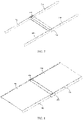
FIG. 1 is a schematic structural diagram of a support structure in an unfolded state according to an embodiment of the present invention; -
FIG. 2 is a schematic structural diagram of a support structure in a folded state according to an embodiment of the present invention; -
FIG. 3 is a schematic structural diagram of a first supporting rod in a support structure according to an embodiment of the present invention; -
FIG. 4 is an enlarged view of part I inFIG. 3 ; -
FIG. 5 is a schematic structural diagram of a support structure in an assembly process according to an embodiment of the present invention; -
FIG. 6 is an enlarged view of part II inFIG. 5 ; -
FIG. 7 is another schematic structural diagram of a support structure in an assembly process according to an embodiment of the present invention; -
FIG. 8 is still another schematic structural diagram of a support structure in an assembly process according to an embodiment of the present invention; -
FIG. 9 is a schematic diagram of part of a support structure in an unfolded state according to an embodiment of the present invention; -
FIG. 10 is an enlarged view of part III inFIG. 9 ; -
FIG. 11 is a schematic diagram of a support structure in an unfolded state according to an embodiment of the present invention; -
FIG. 12 is an enlarged view of part IV inFIG. 11 ; -
FIG. 13 is a schematic diagram of a display assembly in a folded state according to an embodiment of the present invention; and -
FIG. 14 is an enlarged view of part V inFIG. 13 . - Reference signs:
- 100: first support, 110: first connecting portion, 120: first gear teeth, 130: first supporting rod, 140: second supporting rod, 150: first supporting plate, 160: first housing, 170: first supporting portion, 180: first limiting groove;
- 200: second support, 210: second connecting portion, 220: second gear teeth, 230: third supporting rod, 240: fourth supporting rod, 250: second supporting plate, 260: second housing, 270: second supporting portion, 280: second limiting groove;
- 300: third support, 310: first slot for moving, 320: second slot for moving;
- 400: end cover, 410: first rotating shaft, 420: second rotating shaft;
- 500: base, 510: main body portion, 520: first limiting portion, 530: second limiting portion, 540: third limiting portion; and
- 600: flexible display.
- To make the objectives, technical solutions, and advantages of the present invention clearer, the following clearly and completely describes the technical solutions of the present invention with reference to the specific embodiments of the present invention and the corresponding accompanying drawings. Apparently, the described embodiments are merely some rather than all of the embodiments of the present invention. All other embodiments obtained by persons of ordinary skill in the art based on the embodiments of the present invention without creative efforts shall fall within the scope of protection of the present invention.
- The technical solutions disclosed in the embodiments of the present invention are described in detail below with reference to the accompanying drawings.
- As shown in
FIG. 1 to FIG. 14 , an embodiment of the present invention discloses a support structure, which can be applied to an electronic device to support aflexible display 600. As shown inFIG. 1 , the support structure includes afirst support 100, asecond support 200, and athird support 300. - The
first support 100 has a first supporting surface, and thefirst support 100 is provided with a first connectingportion 110. Thesecond support 200 and thefirst support 100 are rotatable relative to each other about an axis of rotation. Thesecond support 200 has a second supporting surface and is provided with a second connectingportion 210. The first connectingportion 110 and the second connectingportion 210 are both spaced apart from the axis of rotation. It should be noted that the axis of rotation is a virtual rotating shaft, which may be located on thefirst support 100 and/or thesecond support 200, or may be located outside thefirst support 100 and thesecond support 200. - Specifically, the
first support 100 and thesecond support 200 may be spaced apart from each other, and both thefirst support 100 and thesecond support 200 can be mounted onto a mounting base such as a housing, so that thefirst support 100 and thesecond support 200 are both rotatable relative to the housing. Alternatively, thefirst support 100 and thesecond support 200 may be connected to each other, and thefirst support 100 is rotatable relative to thesecond support 200 about the axis of rotation. - It should be noted that structures of the
first support 100 and thesecond support 200 may be the same or different. In the present invention, the structures of thefirst support 100 and thesecond support 200 being the same is used as an example. The structures of the first support and the second support being the same facilitates processing and assembling of the support structure. The first connectingportion 110 and thefirst support 100 may be formed integrally, and the second connectingportion 210 and thesecond support 200 may also be formed integrally. - The
third support 300 has a third supporting surface, and thethird support 300 is rotatably mounted onto the first connectingportion 110 and the second connectingportion 210. To ensure that the support structure has relatively high structural strength, thefirst support 100, the first connectingportion 110, thesecond support 200, the second connectingportion 210, and thethird support 300 can all be made of hard materials such as metal. - During use of the support structure, a display screen including the
flexible display 600 can be supported on the first supporting surface, the second supporting surface, and the third supporting surface. Specifically, the display screen may be an integralflexible display 600, and in this case, theflexible display 600 may be supported on the first supporting surface, the second supporting surface, and the third supporting surface at the same time. In some other embodiments of the present invention, alternatively, the display screen may include theflexible display 600, a first rigid display, and a second rigid display, and the first rigid display and the second rigid display may be connected to two opposite sides of theflexible display 600 respectively to form the entire display screen. In this case, the first rigid display may be supported on the first supporting surface, the second rigid display may be supported on the second supporting surface, and theflexible display 600 may be supported on the third supporting surface. - The support structure has an unfolded state and a folded state. In a case that the support structure is in an unfolded state, as described above, the display screen including the
flexible display 600 can be supported on the first supporting surface, the second supporting surface, and the third supporting surface, so that the support structure can provide reliable support for the flexible display. - In a case that the support structure is in a folded state, the first supporting surface and the second supporting surface each form a specific included angle with the third supporting surface to ensure that the support structure is in a folded state and improve portability of the support structure and the electronic device. In addition, in a case that the support structure is in a folded state, the
third support 300 is located between thefirst support 100 and thesecond support 200, and the first supporting surface and the second supporting surface are both spaced apart from the third supporting surface, that is, there are preset distances between the first supporting surface and the third supporting surface, and between the second supporting surface and the third supporting surface. In this way, in the process of folding thefirst support 100 and thesecond support 200 toward each other, a space between the first supporting surface and the third supporting surface and a space between the second supporting surface and the third supporting surface can both be used as an accommodating space to provide accommodation for a component such as the flexible display located on the inner side of the electronic device, preventing the flexible display from being creased in the process of being folded. - Specifically, in the process of folding the
flexible display 600 along with the support structure, part of theflexible display 600 corresponding to the space between the first supporting surface and the third supporting surface can extend into the space between the first supporting surface and the third supporting surface through deformation. The foregoing space can accommodate part of the structure of theflexible display 600, thereby preventing theflexible display 600 from being creased in the process of being folded. Similarly, the space between the second supporting surface and the third supporting surface can also provide accommodation for theflexible display 600, and the spaces on two opposite sides of the third supporting surface each are used as an accommodating space for theflexible display 600 to disperse a bending stress in a region where theflexible display 600 is bent, so as to prevent theflexible display 600 from being easily damaged due to a large folding angle in the process of being folded. - In addition, in a case that the support structure is in a folded state, the first supporting surface and the second supporting surface are arranged facing each other. In other words, when the first supporting surface and the second supporting surface are located between the first support and the second support, the flexible display of the electronic device is located between the first support and the second support, so that the first support and the second support can provide protection for the flexible display, preventing damage to the flexible display when the electronic device is bumped or dropped.
- Optionally, in a case that the support structure is in an unfolded state, the first supporting surface, the second supporting surface, and the third supporting surface can be coplanar. In this way, the
first support 100, thethird support 300, and thesecond support 200 can provide better support for the display screen. In addition, with the foregoing solution, in a case that the support structure is in an unfolded state, theflexible display 600 supported on thethird support 300 can be flatter, which can improve a display effect to some extent. - Specifically, the
first support 100, thethird support 300, and thesecond support 200 may be plate-like structural members, or all the three may include plate-like structural members. The plate-like structural members each have at least one flat surface as the first supporting surface, the third supporting surface, or the second supporting surface. When thefirst support 100 and thesecond support 200 are rotated 180° relative to each other, that is, when the first support and the second support are rotated until the support structure is in an unfolded state, the first supporting surface, the third supporting surface, and the second supporting surface can be coplanar. - As described above, both the
first support 100 and thesecond support 200 may be mounted onto a mounting base such as a housing, and in this case, thefirst support 100 and thesecond support 200 may be spaced apart from each other. Then, the first connectingportion 110 may be disposed at an end of thefirst support 100 close to thesecond support 200, and correspondingly, the second connectingportion 210 may be disposed at an end of thesecond support 200 close to thefirst support 100. In this case, thethird support 300 may be located between thefirst support 100 and thesecond support 200. - In another embodiment of the present invention, the
first support 100 and thesecond support 200 may be connected to each other. In this case, thethird support 300 may be disposed in a region enclosed by thefirst support 100 and thesecond support 200. In other words, in the direction of the axis of rotation, thethird support 300 is located inside thefirst support 100. - Optionally, an outer edge of the
first support 100 is provided with a plurality offirst gear teeth 120, an outer edge of thesecond support 200 is provided with a plurality ofsecond gear teeth 220, and thefirst support 100 rotatably fits with thesecond support 200 via engagement of thefirst gear teeth 120 and thesecond gear teeth 220. Therefore, when thefirst support 100 is rotated alone, thesecond support 200 can be rotated accordingly via the engagement of thefirst gear teeth 120 and thesecond gear teeth 220. In this way, a user can fold or unfold the support structure only with a small angle of rotation during use of the support structure, which can also improve a response speed of the support structure. - Specifically, parameters such as respective tooth widths of the
first gear teeth 120 and thesecond gear teeth 220 may be determined depending on actual conditions, and it is ensured that thefirst gear teeth 120 and thesecond gear teeth 220 can engage with each other. To reduce the difficulty of processing, thefirst gear teeth 120 may be provided only on part of the outer edge of thefirst support 100, and correspondingly, thesecond gear teeth 220 may be provided only on part of the outer edge of thesecond support 200 corresponding to thefirst gear teeth 120. - With the foregoing technical solution, the
first support 100 can fit with thesecond support 200 without using another component for mounting. After thefirst support 100 and thesecond support 200 are connected to each other via theflexible display 600, the engagement relationship between thefirst gear teeth 120 and thesecond gear teeth 220 can ensure that thefirst support 100 and thesecond support 200 can rotate relative to each other to complete the folding and unfolding actions of the support structure. - Optionally, as shown in
FIG. 5 to FIG. 8 , thefirst support 100 includes a first supportingrod 130, a second supportingrod 140, and a first supportingplate 150. The first supportingrod 130 is spaced apart from the second supportingrod 140. The first supportingrod 130 and the second supportingrod 140 are both provided with the first connectingportion 110. The first supportingrod 130 and the second supportingrod 140 are both connected to the first supportingplate 150. The first supportingplate 150 has the first supporting surface. - The
first support 100 having the foregoing structure can provide stable support for the display screen, and the overall structure is simple and easy to assemble. In addition, a mounting space can be formed between the first supportingrod 130 and the second supportingrod 140 to provide an accommodating space for the mounting of other components in the electronic device. - As described above, a structure of the
second support 200 may be the same as that of thefirst support 100. Specifically, thesecond support 200 includes a third supportingrod 230, a fourth supportingrod 240, and a second supportingplate 250. The third supportingrod 230 is spaced apart from the fourth supportingrod 240. The third supportingrod 230 and the fourth supportingrod 240 are both provided with the second connectingportion 210. The third supportingrod 230 and the fourth supportingrod 240 are both connected to the second supportingplate 250. The second supportingplate 250 has the second supporting surface. - In addition, the
first support 100 and thesecond support 200 may also be a plate-like structure as a whole, which can also ensure that thefirst support 100 and thesecond support 200 can provide support for the display screen and can both be connected to thethird support 300. Certainly, thefirst support 100 and thesecond support 200 may also be other structures, which, for brevity, are not listed one by one herein. - Optionally, a side wall of at least one of the first supporting
rod 130 and the second supportingrod 140 is provided with a first supportingportion 170, and the first supportingplate 150 is supported on the first supportingportion 170. The side walls of the first support and the second support refer to surfaces of the first supportingrod 130 and the second supportingrod 140 facing the other. - In a case that the side walls of the first supporting
rod 130 and the second supportingrod 140 each are provided with the first supportingportion 170, at least two first supportingportions 170 can provide support for the first supportingplate 150 to ensure that the first supportingplate 150 can provide reliable support for the display screen. In addition, when the side walls of the first supportingrod 130 and the second supportingrod 140 each are provided with the first supportingportion 170, the display screen can be located between the first supportingrod 130 and the second supportingrod 140, so that the first supportingrod 130 and the second supportingrod 140 can provide some coating effect for the display screen, preventing the display screen from being damaged when the support structure mounted with the display screen is bumped. In addition, the display screen being located between the first supportingrod 130 and the second supportingrod 140 can also prevent the display screen from being exposed to cause leakage of electricity or scratch the user. The first supporting plate may be placed on the at least two first supporting portions, or the at least two first supporting portions may be inserted into corresponding grooves of the first supporting plate. The first supporting plate may be connected to the at least two first supporting portions by means of welding, bonding, or the like. - In other embodiments of the present invention, the first supporting
portion 170 may be provided only on one of the first supportingrod 130 and the second supportingrod 140. In this case, stable and reliable support can be provided for the first supportingplate 150 by increasing a length of the first supportingportion 170. In this case, the first supporting plate may be disposed on the first supporting portion, and the first supporting plate is connected to the other supporting rod by means of bonding or welding. Alternatively, the first supporting portion may be embedded in a corresponding groove of the first supporting plate, and the first supporting plate overlaps with the other supporting rod, thereby ensuring stability of the first supporting plate. - Specifically, the disposition of the first supporting
portion 170 may be determined based on a thickness of the display screen that needs to be mounted. In a case that a side surface of the display screen is a curved surface, a distance between the first supportingportion 170 and the top surface of the first supportingrod 130 can be slightly less than the thickness of the display screen, so that a side of the display screen is exposed, preventing the first supportingrod 130 and the second supportingrod 140 from covering display content on the display screen, which can also improve overall aesthetics to some extent. In a case that the side surface of the display screen is a flat surface, the distance between the first supportingportion 170 and the top surface of the first supportingrod 130 can be equal to the thickness of the display screen, thereby ensuring that the display screen can be completely wrapped, and providing good protection for the display screen. - Correspondingly, a side wall of at least one of the third supporting
rod 230 and the fourth supportingrod 240 of thesecond support 200 may be provided with a second supportingportion 270, and the second supportingplate 250 may be supported on the second supportingportion 270. A structure and a connection manner of the second supportingportion 270 in thesecond support 200 are similar to those of the first supportingportion 170 in thefirst support 100 and, for brevity, are not described in detail herein. - In a case that the
first support 100 includes the first supportingrod 130 and the second supportingrod 140, the first supportingrod 130 and the second supportingrod 140 each may be provided with the first connectingportion 110, so that two opposite ends of the third supportingrod 300 can be connected to the two first connectingportions 110 respectively to improve movement stability of thethird support 300. - Optionally, the first connecting
portion 110 is disposed on a side of the first supportingrod 130 facing the second supportingrod 140. In this case, thethird support 300 can be located between the first supportingrod 130 and the second supportingrod 140, so that the number of exposed structural members in the support structure can be reduced, which reduces a probability of damage to the support structure; and the number of gaps between the support structure and the outside can be reduced, which further prevents external impurities from entering the support structure. - In a case that the first supporting
rod 130 and the second supportingrod 140 are both provided with the first connectingportion 110, one first connectingportion 110 may be located on a surface of the first supportingrod 130 facing the second supportingrod 140, and the other first connectingportion 110 may be located on a surface of the second supportingrod 140 facing the first supportingrod 130. - Correspondingly, the
second support 200 may also be provided with two second connectingportions 210, which may be provided on a side of the third supportingrod 230 facing the fourth supportingrod 240 and a side of the fourth supportingrod 240 facing the third supportingrod 230 respectively, so that two opposite ends of thethird support 300 can be connected to the two second connectingportions 210 respectively. - Based on the foregoing embodiment, in a case that the first connecting
portion 110 is located on the side of the first supportingrod 130 facing the second supportingrod 140, the first connectingportion 110 may also be located at an end of the first supportingrod 130 close to thesecond support 200. In this way, an overall size of thethird support 300 is reduced, and in the process of folding and unfolding the support structure, no gap of a large size appears between thefirst support 100 and thesecond support 200, so that an overall size of the support structure in a folded state is relatively small, which further improves portability of the support structure and the electronic device. - Correspondingly, in a case that the second connecting
portion 210 is located on the side of the third supportingrod 230 facing the fourth supportingrod 240, the second connectingportion 210 may also be located at an end of the third supportingrod 230 close to thefirst support 100. - Optionally, the
third support 300 is a plate-like structure, and thethird support 300 may be supported on the first connectingportion 110 and the second connectingportion 210. In this way, during the rotation of the first connectingportion 110 and the second connectingportion 210 relative to each other about the axis of rotation, even if the first connectingportion 110 and the second connectingportion 210 move relative to each other, it can be ensured that thethird support 300 can move relative to the first connectingportion 110 and the second connectingportion 210, so that thethird support 300 can be stably supported on the first connectingportion 110 and the second connectingportion 210. - In another embodiment of the present invention, as shown in
FIG. 12 , thethird support 300 is provided with a first slot for moving 310, and the first connectingportion 110 is inserted into the first slot for moving 310. In a direction perpendicular to the axis of rotation, the first connectingportion 110 may movably fit with the first slot for moving 310, so that thethird support 300 can move relative to the first connectingportion 110. - In addition, in a case that the first supporting
rod 130 and the second supportingrod 140 are both provided with the first connectingportion 110, and the two opposite ends of thethird support 300 are inserted into the two first connectingportions 110 respectively, the first supportingrod 130 and the second supportingrod 140 can provide a limiting effect for thethird support 300 in the direction of the axis of rotation, and the two first connectingportions 110 can provide a limiting effect for thethird support 300 in the direction perpendicular to the axis of rotation, so that movement stability of thethird support 300 is relatively high. - Specifically, a size of the first slot for moving 310 may be determined based on parameters such as a size and a movement range of the first connecting
portion 110. Since the first connectingportion 110 rotates relative to the first slot for moving 310 during the rotation about the axis of rotation. Optionally, the first connectingportion 110 may be a cylindrical structure. When such a structure is used, the first slot for moving 310 may be provided as a waist-shaped hole. In addition, a radius of the waist-shaped hole only needs to be slightly greater than that of the first connectingportion 110 to ensure that the first connectingportion 110 can rotate relative to the first slot for moving 310. The overall structural strength of thethird support 300 is relatively high with the size of the waist-shaped hole being relatively small. - In addition, because the second connecting
portion 210 is also connected to thethird support 300, in a case that the first slot for moving 310 is provided at an end of thethird support 300, a second slot for moving 320 needs to be further provided so that the second connectingportion 210 can movably fit with the second slot for moving 320. - Specifically, in a case that the first slot for moving 310 is a waist-shaped hole, the second slot for moving 320 may be a circular hole. In this case, the second connecting
portion 210 may also be a circular structural member, and the second connectingportion 210 is inserted into the circular hole, so that during the relative movement of the first connectingportion 110 and the second connectingportion 210, thethird support 300 moves along with the movement of the second connectingportion 210. A change of a distance between the first connectingportion 110 and the second connectingportion 210 can be compensated only by the first slot for moving 310 fitting with the first connectingportion 110 to ensure that the first connectingportion 110 and the second connectingportion 210 can normally drive thethird support 300 to move. - In another embodiment of the present invention, the first slot for moving 310 and the second slot for moving 320 are both waist-shaped holes. In this case, because the
third support 300 can move relative to the first connectingportion 110 and can also move relative to the second connectingportion 210, during the relative movement of the first connectingportion 110 and the second connectingportion 210, a position of thethird support 300 can be kept unchanged in a direction of a connecting line between the first connectingportion 110 and the second connectingportion 210. This prevents a gap between thethird support 300 and thefirst support 100 or thesecond support 200 from being too large to adversely affects air tightness of the support structure and other performance. In addition, this can also prevent thethird support 300 from moving toward thefirst support 100 or thesecond support 200 in the above-mentioned direction for an excessively large distance to cause thethird support 300 to collide with thefirst support 100 or thesecond support 200 and damage the support structure. - Further, the support structure disclosed in this embodiment of the present invention may further include an
end cover 400 provided with a firstrotating shaft 410 and a secondrotating shaft 420. The firstrotating shaft 410 and the secondrotating shaft 420 both extend in the direction of the axis of rotation. Thefirst support 100 is hinged to the firstrotating shaft 410, and thesecond support 200 is hinged to the secondrotating shaft 420. With connection of theend cover 400, stability and reliability during the relative rotation between thefirst support 100 and thesecond support 200 can be further improved. In addition, two end covers 400 may be provided, which are disposed on two opposite sides of thefirst support 100 respectively, that is, the two end covers 400 are located outside the first supportingrod 130 and the second supportingrod 140 respectively. The two end covers 400 may be connected to the mounting base such as a housing, so as to ensure high connection reliability between the end covers 400 and thefirst support 100 and thesecond support 200. - Specifically, the
first support 100 and thesecond support 200 each may be provided with a fitting hole. Thefirst support 100 can be hinged onto theend cover 400 by inserting the firstrotating shaft 410 into the fitting hole of thefirst support 100. Thesecond support 200 can be hinged onto theend cover 400 by inserting the secondrotating shaft 420 into the fitting hole of thesecond support 200. - Correspondingly, the
end cover 400 may further be provided with the secondrotating shaft 420, and thesecond support 200 is hinged to the secondrotating shaft 420, so as to further improve fitting stability between thefirst support 100 and thesecond support 200. - In a case that the two end covers 400 are disposed on the two opposite sides of the first support 100 (and/or the second support 200) respectively, optionally, the support structure disclosed in this embodiment of the present invention may further include a
base 500. The two end covers 400 are connected to each other by means of thebase 500, so that fitting relationship between the two end covers 400 and thefirst support 100 and thesecond support 200 is more stable. - In addition, the
base 500 is disposed on a side of thefirst support 100 away from the first supporting surface. Thebase 500 is connected to thefirst support 100 and thesecond support 200 and can provide a more comprehensive coating effect for the display screen disposed on a side of the first supporting surface and the second supporting surface. In addition, the base 500 can provide some protection for thethird support 300, so that movable components of the entire support structure are not exposed as much as possible, thereby prolonging service life of the support structure. - Further, the
base 500 includes amain body portion 510, a first limitingportion 520, and a second limitingportion 530. The first limitingportion 520 is connected to one side of themain body portion 510, and the second limitingportion 530 is connected to the other side of themain body portion 510. The first limitingportion 520 and the second limitingportion 530 are both arc-shaped structural members. A side of thefirst support 100 away from the first supporting surface is provided with a first limitinggroove 180, and a side of thesecond support 200 away from the second supporting surface is provided with a second limitinggroove 280. In a case that the support structure is in an unfolded state, the first limitingportion 520 extends into the first limitinggroove 180 and fits with thefirst support 100 at a limited position, and the second limitingportion 530 extends into the second limitinggroove 280 and fits with thesecond support 200 at a limited position. - After the foregoing structure is used, when the support structure is in an unfolded state, the base 500 can be mutually limited with the
first support 100 and thesecond support 200. In addition, the first limitingportion 520 extends in a direction approaching the first supporting surface, and the first limitingportion 520 is an arc-shaped structural member; and the second limitingportion 530 extends in a direction approaching the second supporting surface, and the second limitingportion 530 is an arc-shaped structural member. Therefore, when the support structure is in a folded state, the first limitingportion 520 can coat thefirst support 100, and the second limitingportion 520 can coat thesecond support 200. Further, thefirst support 100, the first limitingportion 520, themain body portion 510, the second limitingportion 530, and thesecond support 200 can coat the display screen and thethird support 300 to prevent the display screen and thethird support 300 from being damaged due to an exposed part when a bump occurs. - In a case that the
base 500 is provided, optionally, thebase 500 may also include themain body portion 510 and a third limitingportion 540. The third limitingportion 540 is connected to themain body portion 510 and is disposed on a side of themain body portion 510 away from the first supporting surface. When the support structure is in an unfolded state, the third limitingportion 540 is sandwiched between thefirst support 100 and thesecond support 200. - When the foregoing structure is used, in the process of switching the support structure from the folded state to the unfolded state, endpoint positions of the
first support 100 and thesecond support 200 during the rotation can be limited by the third limitingportion 540 to prevent thefirst support 100 and thesecond support 200 from an excessive rotation that damages the display screen connected to the support structure. Specifically, the third limitingportion 540 and themain body portion 510 may be formed integrally, the third limitingportion 540 is located on an outer periphery of themain body portion 510, and an angle spanned by the third limitingportion 540 may be determined depending on actual needs. - In addition, the
base 500 may include themain body portion 510, the first limitingportion 520, the second limitingportion 530, and the third limitingportion 540. The first limitingportion 520, the second limitingportion 530, and the third limitingportion 540 are all connected onto themain body portion 510, and the first limitingportion 520 and the second limitingportion 530 are located on two opposite sides of the third limitingportion 540 respectively. The respective shapes and position relationships of the first limitingportion 520, the second limitingportion 530, and the third limitingportion 540 have been clearly described above, and details are not repeated here. - Optionally, the support structure may further include a
first housing 160 and asecond housing 260. Thefirst housing 160 is mounted on a side of thefirst support 100 away from the first supporting surface, and thefirst housing 160 can provide protection for other components mounted in thefirst support 100. Thesecond housing 260 is mounted on a side of thesecond support 200 away from the second supporting surface, and thesecond housing 260 can provide protection for other components mounted in thesecond support 200. Specifically, thefirst housing 160 and thesecond housing 260 both may be made of hard materials such as metal, and their sizes and specific shapes may be determined according to corresponding sizes of thefirst support 100 and thesecond support 200. - Based on the support structure disclosed in the foregoing embodiment, an embodiment of the present invention further discloses a display assembly. The display assembly includes a display screen and the support structure disclosed in any one of the foregoing embodiments, and the display screen is mounted onto the support structure. As described above, the display screen may be an integral
flexible display 600. In this case, part of theflexible display 600 is fixedly connected to thethird support 300, so that theflexible display 600 can deform along with the movement of thethird support 300 in the process of folding and unfolding the display assembly. In addition, part of the structure of theflexible display 600 can extend into between the first supporting surface and the third supporting surface and between the second supporting surface and the third supporting surface through deformation, preventing theflexible screen 600 from being creased in the process of being folded. - Alternatively, the display screen may include the
flexible display 600, a first rigid display, and a second rigid display, and the first rigid display and the second rigid display may be connected to two opposite sides of theflexible display 600 respectively to form the entire display screen. In this case, the first rigid display may be supported on the first supporting surface, the second rigid display may be supported on the second supporting surface, theflexible display 600 may be supported on the third supporting surface, and part of theflexible display 600 may be connected to the third supporting surface. Similarly, theflexible display 600 can also deform along with the movement of thethird support 300, and part of the structure of theflexible display 600 can extend into between the first supporting surface and the third supporting surface and between the second supporting surface and the third supporting surface through deformation, preventing theflexible screen 600 from being creased in the process of being folded. - Based on the display assembly disclosed in the foregoing embodiment, an embodiment of the present invention further discloses an electronic device. The electronic device includes the display assembly disclosed in the foregoing embodiment. Certainly, the electronic device may further include a battery and other components, and the display assembly may be connected to the battery. The structure composition and connection relationship of the display assembly including the support structure and the display screen have been described in detail based on the foregoing description, and for brevity, details are not repeated here.
- The electronic device disclosed in this embodiment of the present invention may be a smart phone, a tablet computer, an e-book reader, or a wearable device. Certainly, the electronic device may alternatively be other devices, which is not limited in the embodiments of the present invention.
- The foregoing embodiments of the present invention focus on the differences between the embodiments. As long as the different features of improvement in the embodiments are not contradictory, they can be combined to form a more preferred embodiment. For brevity, details are not repeated here.
- The foregoing descriptions are merely embodiments of the present invention and are not intended to limit the present invention. For a person skilled in the art, the present invention may have various changes and variations. Any modification, equivalent replacement, improvement, or the like made without departing from the spirit and principle of the present invention shall fall within the scope of claims of the present invention.
Claims (15)
- A support structure, comprising:a first support having a first supporting surface and provided with a first connecting portion;a second support rotatably fitting with the first support about an axis of rotation, wherein the second support has a second supporting surface and is provided with a second connecting portion, and the first connecting portion and the second connecting portion are both spaced apart from the axis of rotation; anda third support having a third supporting surface and rotatably connected to both the first connecting portion and the second connecting portion, wherein when the support structure is in a folded state, the first supporting surface and the second supporting surface are spaced apart from the third supporting surface, and the first supporting surface and the second supporting surface each form a specific included angle with the third supporting surface.
- The support structure according to claim 1, wherein an outer edge of the first support is provided with a plurality of first gear teeth, an outer edge of the second support is provided with a plurality of second gear teeth, and the first support rotatably fits with the second support via engagement of the first gear teeth and the second gear teeth.
- The support structure according to claim 1, wherein the first support comprises a first supporting rod, a second supporting rod, and a first supporting plate, the first supporting rod is spaced apart from the second supporting rod, the first supporting rod and the second supporting rod are both provided with the first connecting portion, each of the first connecting portions rotatably connected to the third support, the first supporting rod and the second supporting rod are both connected to the first supporting plate, and the first supporting plate has the first supporting surface; and
the second support comprises a third supporting rod, a fourth supporting rod, and a second supporting plate, the third supporting rod is spaced apart from the fourth supporting rod, the third supporting rod and the fourth supporting rod are both provided with the second connecting portion, each of the second connecting portions rotatably connected to the third support, the third supporting rod and the fourth supporting rod are both connected to the second supporting plate, and the second supporting plate has the second supporting surface. - The support structure according to claim 3, wherein a side wall of at least one of the first supporting rod and the second supporting rod is provided with a first supporting portion, and the first supporting plate is supported by the first supporting portion; and
a side wall of at least one of the third supporting rod and the fourth supporting rod is provided with a second supporting portion, and the second supporting plate is supported by the second supporting portion. - The support structure according to claim 3, wherein the first connecting portion is located on a side of the first supporting rod facing the second supporting rod; and the second connecting portion is located on a side of the third supporting rod facing the fourth supporting rod.
- The support structure according to claim 5, wherein the first connecting portion is located at an end of the first supporting rod close to the second support, and the second connecting portion is located at an end of the third supporting rod close to the first support.
- The support structure according to claim 1, wherein the third support is provided with a first slot for moving and a second slot for moving; the first connecting portion is inserted into the first slot for moving, and the first connecting portion is movable relative to the first slot for moving; and the second connecting portion is inserted into the second slot for moving, and the second connecting portion is movable relative to the second slot for moving.
- The support structure according to claim 1, wherein the support structure further comprises an end cover provided with a first rotating shaft and a second rotating shaft, the first rotating shaft and the second rotating shaft both extend along the axis of rotation, the first rotating shaft is hinged to the first support, and the second rotating shaft is hinged to the second support.
- The support structure according to claim 8, wherein the support structure further comprises a base, there are two end covers disposed on two opposite sides of the first support respectively and connected by means of the base, and the base is disposed on a side of the first support away from the first supporting surface.
- The support structure according to claim 9, wherein the base comprises a main body portion, a first limiting portion, and a second limiting portion, the first limiting portion and the second limiting portion are both connected to the main body portion and are located on two opposite sides of the main body portion respectively, the first limiting portion and the second limiting portion are both arc-shaped structural members, a side of the first support away from the first supporting surface is provided with a first limiting groove, a side of the second support away from the second supporting surface is provided with a second limiting groove, and when the support structure is in an unfolded state, the first limiting portion extends into the first limiting groove and fits with the first support at a limited position, and the second limiting portion extends into the second limiting groove and fits with the second support at a limited position.
- The support structure according to claim 9, wherein the base comprises a main body portion and a third limiting portion, the third limiting portion is connected to the main body portion, the third limiting portion is disposed on a side of the main body portion away from the first supporting surface, and when the support structure is in an unfolded state, the third limiting portion is sandwiched between the first support and the second support.
- The support structure according to claim 1, wherein the support structure further comprises a first housing and a second housing, the first housing is mounted on a side of the first support away from the first supporting surface, and the second housing is mounted on a side of the second support away from the second supporting surface.
- The support structure according to claim 1, wherein when the support structure is in an unfolded state, the first supporting surface, the second supporting surface, and the third supporting surface are coplanar.
- A display assembly, comprising a flexible display and the support structure according to any one of claims 1 to 13, wherein the flexible display is mounted onto the support structure, and part of the flexible display is fixedly connected to the third support.
- An electronic device, comprising the display assembly according to claim 14.
Applications Claiming Priority (2)
| Application Number | Priority Date | Filing Date | Title |
|---|---|---|---|
| CN202010328293.1A CN113551105B (en) | 2020-04-23 | 2020-04-23 | Support structure, screen assembly and electronic equipment |
| PCT/CN2021/089380 WO2021213509A1 (en) | 2020-04-23 | 2021-04-23 | Support structure, screen assembly and electronic device |
Publications (3)
| Publication Number | Publication Date |
|---|---|
| EP4142267A1 true EP4142267A1 (en) | 2023-03-01 |
| EP4142267A4 EP4142267A4 (en) | 2023-10-18 |
| EP4142267B1 EP4142267B1 (en) | 2025-12-03 |
Family
ID=78101090
Family Applications (1)
| Application Number | Title | Priority Date | Filing Date |
|---|---|---|---|
| EP21791591.7A Active EP4142267B1 (en) | 2020-04-23 | 2021-04-23 | Support structure, screen assembly and electronic device |
Country Status (7)
| Country | Link |
|---|---|
| US (1) | US12160965B2 (en) |
| EP (1) | EP4142267B1 (en) |
| JP (1) | JP7479505B2 (en) |
| KR (1) | KR102752724B1 (en) |
| CN (1) | CN113551105B (en) |
| ES (1) | ES3058399T3 (en) |
| WO (1) | WO2021213509A1 (en) |
Families Citing this family (10)
| Publication number | Priority date | Publication date | Assignee | Title |
|---|---|---|---|---|
| CN112145542B (en) * | 2019-06-27 | 2022-01-11 | 华为技术有限公司 | Folding module and folding electronic equipment |
| CN114079679B (en) * | 2020-08-17 | 2023-02-03 | 华为技术有限公司 | Foldable electronic device |
| CN214063552U (en) * | 2020-12-15 | 2021-08-27 | 合肥维信诺科技有限公司 | A bending unit, hinge and flexible module bending device |
| CN114245625B (en) * | 2021-12-15 | 2024-09-27 | 维沃移动通信有限公司 | Electronic devices |
| CN116557406A (en) * | 2022-01-30 | 2023-08-08 | 华为技术有限公司 | Rotating shaft mechanism and electronic equipment |
| US12092151B2 (en) * | 2022-06-17 | 2024-09-17 | Microsoft Technology Licensing, Llc | Multi-pivot timing chain with link flexures |
| CN117685286A (en) * | 2022-09-02 | 2024-03-12 | 荣耀终端有限公司 | Folding components, folding devices and terminal equipment |
| CN115862471B (en) * | 2022-11-24 | 2025-05-06 | 合肥维信诺科技有限公司 | Foldable support device and foldable display device |
| CN117156026B (en) * | 2023-01-04 | 2024-10-01 | 荣耀终端有限公司 | Screen assembly structure and assembly method thereof, and electronic device |
| CN220749658U (en) * | 2023-08-22 | 2024-04-09 | 深圳市立点科技有限公司 | A fully foldable computer stand |
Family Cites Families (20)
| Publication number | Priority date | Publication date | Assignee | Title |
|---|---|---|---|---|
| KR102034585B1 (en) * | 2013-07-09 | 2019-10-21 | 엘지전자 주식회사 | Display Device |
| KR102202228B1 (en) * | 2014-06-11 | 2021-01-13 | 삼성전자 주식회사 | Electronic device comprising a flexible display |
| KR102233119B1 (en) * | 2014-09-23 | 2021-03-30 | 삼성디스플레이 주식회사 | Display device |
| KR102322377B1 (en) * | 2014-12-31 | 2021-11-05 | 엘지디스플레이 주식회사 | Foldable display apparatus |
| KR101752708B1 (en) * | 2015-04-09 | 2017-07-04 | 삼성전자주식회사 | Foldable device |
| CN206619066U (en) * | 2017-04-13 | 2017-11-07 | 上海天马微电子有限公司 | Folding terminal |
| KR102324508B1 (en) * | 2017-06-28 | 2021-11-09 | 엘지디스플레이 주식회사 | Foldable display apparatus |
| US10863641B2 (en) * | 2017-12-04 | 2020-12-08 | Lg Display Co., Ltd. | Foldable display apparatus |
| KR102645561B1 (en) * | 2017-12-04 | 2024-03-08 | 엘지디스플레이 주식회사 | Display apparatus |
| CN207777905U (en) * | 2017-12-06 | 2018-08-28 | 杭州安费诺飞凤通信部品有限公司 | A kind of hinge and infolding flexible screen mobile terminal of infolding flexible screen mobile terminal |
| CN108055371A (en) * | 2018-01-26 | 2018-05-18 | 努比亚技术有限公司 | A kind of fold mechanism and Foldable mobile terminal |
| US10491725B1 (en) * | 2018-09-14 | 2019-11-26 | Motorola Mobility Llc | Hinged electronic device with moving support plates for a flexible display and corresponding systems |
| CN209710124U (en) * | 2018-11-06 | 2019-11-29 | Oppo广东移动通信有限公司 | Electronic equipment |
| CN109669513B (en) * | 2018-11-06 | 2022-05-17 | Oppo广东移动通信有限公司 | Electronic device |
| CN109780403B (en) * | 2019-01-29 | 2020-08-18 | 维沃移动通信有限公司 | Rotary connecting assembly and folding terminal equipment |
| CN109637377B (en) * | 2019-01-31 | 2021-03-16 | 武汉华星光电半导体显示技术有限公司 | Foldable display device |
| CN210201872U (en) * | 2019-05-28 | 2020-03-27 | 珠海格力电器股份有限公司 | Screen folding structure and mobile terminal with same |
| CN210041894U (en) | 2019-08-02 | 2020-02-07 | 东莞市环力智能科技有限公司 | Folding pivot in flexible screen |
| CN110599907A (en) * | 2019-09-05 | 2019-12-20 | 武汉华星光电半导体显示技术有限公司 | Foldable display device |
| CN111009192A (en) | 2019-12-31 | 2020-04-14 | 武汉华星光电半导体显示技术有限公司 | Display panel support frame and display device |
-
2020
- 2020-04-23 CN CN202010328293.1A patent/CN113551105B/en active Active
-
2021
- 2021-04-23 JP JP2022563893A patent/JP7479505B2/en active Active
- 2021-04-23 EP EP21791591.7A patent/EP4142267B1/en active Active
- 2021-04-23 WO PCT/CN2021/089380 patent/WO2021213509A1/en not_active Ceased
- 2021-04-23 ES ES21791591T patent/ES3058399T3/en active Active
- 2021-04-23 KR KR1020227038667A patent/KR102752724B1/en active Active
-
2022
- 2022-10-14 US US17/966,290 patent/US12160965B2/en active Active
Also Published As
| Publication number | Publication date |
|---|---|
| US20230032983A1 (en) | 2023-02-02 |
| KR102752724B1 (en) | 2025-01-10 |
| CN113551105A (en) | 2021-10-26 |
| CN113551105B (en) | 2022-11-25 |
| JP7479505B2 (en) | 2024-05-08 |
| US12160965B2 (en) | 2024-12-03 |
| WO2021213509A1 (en) | 2021-10-28 |
| KR20220162791A (en) | 2022-12-08 |
| JP2023522373A (en) | 2023-05-30 |
| EP4142267B1 (en) | 2025-12-03 |
| EP4142267A4 (en) | 2023-10-18 |
| ES3058399T3 (en) | 2026-03-10 |
Similar Documents
| Publication | Publication Date | Title |
|---|---|---|
| US12160965B2 (en) | Support structure, display assembly, and electronic device | |
| JP7203991B2 (en) | Pivoting connection assemblies and folding terminals | |
| EP4311209A1 (en) | Folding mechanism and electronic device | |
| US20240040723A1 (en) | Foldable display device | |
| CN107408362B (en) | Bendable Mobile Terminal | |
| US20230021638A1 (en) | Foldable display device | |
| US12608051B2 (en) | Folding mechanism and terminal device | |
| EP4477898A1 (en) | Hinge mechanism and electronic device | |
| US20240028084A1 (en) | Foldable hinge and foldable display device | |
| US20240098164A1 (en) | Rotation Mechanism and Foldable Terminal | |
| US20220248550A1 (en) | Electronic device | |
| US20120033353A1 (en) | Foldable electronic device | |
| CN107358874A (en) | A flexible display device | |
| US20230131590A1 (en) | Foldable mobile terminal, and heat dissipation system and housing thereof | |
| US20250275073A1 (en) | Hinge Mechanism and Electronic Device | |
| EP3817344A1 (en) | Rotating shaft body and electronic device | |
| US11283911B2 (en) | Hinge, folding mechanism, and terminal device | |
| US20240402758A1 (en) | Hinge and foldable display device | |
| US20240341047A1 (en) | Display apparatus | |
| CN222125594U (en) | Light blocking structure and spotlight | |
| JP6223510B1 (en) | Case of portable terminal | |
| CN120604503A (en) | A rotating shaft mechanism and a folding screen terminal |
Legal Events
| Date | Code | Title | Description |
|---|---|---|---|
| STAA | Information on the status of an ep patent application or granted ep patent |
Free format text: STATUS: THE INTERNATIONAL PUBLICATION HAS BEEN MADE |
|
| PUAI | Public reference made under article 153(3) epc to a published international application that has entered the european phase |
Free format text: ORIGINAL CODE: 0009012 |
|
| STAA | Information on the status of an ep patent application or granted ep patent |
Free format text: STATUS: REQUEST FOR EXAMINATION WAS MADE |
|
| 17P | Request for examination filed |
Effective date: 20221117 |
|
| AK | Designated contracting states |
Kind code of ref document: A1 Designated state(s): AL AT BE BG CH CY CZ DE DK EE ES FI FR GB GR HR HU IE IS IT LI LT LU LV MC MK MT NL NO PL PT RO RS SE SI SK SM TR |
|
| DAV | Request for validation of the european patent (deleted) | ||
| DAX | Request for extension of the european patent (deleted) | ||
| A4 | Supplementary search report drawn up and despatched |
Effective date: 20230920 |
|
| RIC1 | Information provided on ipc code assigned before grant |
Ipc: F16C 11/04 20060101ALI20230914BHEP Ipc: G06F 1/16 20060101ALI20230914BHEP Ipc: G09F 9/30 20060101ALI20230914BHEP Ipc: H04M 1/02 20060101AFI20230914BHEP |
|
| GRAP | Despatch of communication of intention to grant a patent |
Free format text: ORIGINAL CODE: EPIDOSNIGR1 |
|
| STAA | Information on the status of an ep patent application or granted ep patent |
Free format text: STATUS: GRANT OF PATENT IS INTENDED |
|
| GRAS | Grant fee paid |
Free format text: ORIGINAL CODE: EPIDOSNIGR3 |
|
| INTG | Intention to grant announced |
Effective date: 20250930 |
|
| GRAA | (expected) grant |
Free format text: ORIGINAL CODE: 0009210 |
|
| STAA | Information on the status of an ep patent application or granted ep patent |
Free format text: STATUS: THE PATENT HAS BEEN GRANTED |
|
| AK | Designated contracting states |
Kind code of ref document: B1 Designated state(s): AL AT BE BG CH CY CZ DE DK EE ES FI FR GB GR HR HU IE IS IT LI LT LU LV MC MK MT NL NO PL PT RO RS SE SI SK SM TR |
|
| REG | Reference to a national code |
Ref country code: CH Ref legal event code: F10 Free format text: ST27 STATUS EVENT CODE: U-0-0-F10-F00 (AS PROVIDED BY THE NATIONAL OFFICE) Effective date: 20251203 Ref country code: GB Ref legal event code: FG4D |
|
| REG | Reference to a national code |
Ref country code: DE Ref legal event code: R096 Ref document number: 602021043701 Country of ref document: DE |
|
| REG | Reference to a national code |
Ref country code: IE Ref legal event code: FG4D |
|
| REG | Reference to a national code |
Ref country code: NL Ref legal event code: FP |
|
| REG | Reference to a national code |
Ref country code: ES Ref legal event code: FG2A Ref document number: 3058399 Country of ref document: ES Kind code of ref document: T3 Effective date: 20260310 |
|
| PGFP | Annual fee paid to national office [announced via postgrant information from national office to epo] |
Ref country code: GB Payment date: 20260312 Year of fee payment: 6 |
|
| REG | Reference to a national code |
Ref country code: LT Ref legal event code: MG9D |
|
| PG25 | Lapsed in a contracting state [announced via postgrant information from national office to epo] |
Ref country code: NO Free format text: LAPSE BECAUSE OF FAILURE TO SUBMIT A TRANSLATION OF THE DESCRIPTION OR TO PAY THE FEE WITHIN THE PRESCRIBED TIME-LIMIT Effective date: 20260303 |
|
| PG25 | Lapsed in a contracting state [announced via postgrant information from national office to epo] |
Ref country code: HR Free format text: LAPSE BECAUSE OF FAILURE TO SUBMIT A TRANSLATION OF THE DESCRIPTION OR TO PAY THE FEE WITHIN THE PRESCRIBED TIME-LIMIT Effective date: 20251203 Ref country code: FI Free format text: LAPSE BECAUSE OF FAILURE TO SUBMIT A TRANSLATION OF THE DESCRIPTION OR TO PAY THE FEE WITHIN THE PRESCRIBED TIME-LIMIT Effective date: 20251203 |
|
| PGFP | Annual fee paid to national office [announced via postgrant information from national office to epo] |
Ref country code: IT Payment date: 20260320 Year of fee payment: 6 |
|
| PGFP | Annual fee paid to national office [announced via postgrant information from national office to epo] |
Ref country code: NL Payment date: 20260317 Year of fee payment: 6 |
|
| PG25 | Lapsed in a contracting state [announced via postgrant information from national office to epo] |
Ref country code: RS Free format text: LAPSE BECAUSE OF FAILURE TO SUBMIT A TRANSLATION OF THE DESCRIPTION OR TO PAY THE FEE WITHIN THE PRESCRIBED TIME-LIMIT Effective date: 20260303 |
|
| PGFP | Annual fee paid to national office [announced via postgrant information from national office to epo] |
Ref country code: FR Payment date: 20260309 Year of fee payment: 6 |
|
| PG25 | Lapsed in a contracting state [announced via postgrant information from national office to epo] |
Ref country code: PL Free format text: LAPSE BECAUSE OF FAILURE TO SUBMIT A TRANSLATION OF THE DESCRIPTION OR TO PAY THE FEE WITHIN THE PRESCRIBED TIME-LIMIT Effective date: 20251203 |
|
| PG25 | Lapsed in a contracting state [announced via postgrant information from national office to epo] |
Ref country code: LV Free format text: LAPSE BECAUSE OF FAILURE TO SUBMIT A TRANSLATION OF THE DESCRIPTION OR TO PAY THE FEE WITHIN THE PRESCRIBED TIME-LIMIT Effective date: 20251203 |
|
| PG25 | Lapsed in a contracting state [announced via postgrant information from national office to epo] |
Ref country code: BG Free format text: LAPSE BECAUSE OF FAILURE TO SUBMIT A TRANSLATION OF THE DESCRIPTION OR TO PAY THE FEE WITHIN THE PRESCRIBED TIME-LIMIT Effective date: 20251203 |