EP4142160A1 - Data compression device, data restoration device, data compression system, control circuit, memory medium, data compression method, and data restoration method - Google Patents
Data compression device, data restoration device, data compression system, control circuit, memory medium, data compression method, and data restoration method Download PDFInfo
- Publication number
- EP4142160A1 EP4142160A1 EP20939240.6A EP20939240A EP4142160A1 EP 4142160 A1 EP4142160 A1 EP 4142160A1 EP 20939240 A EP20939240 A EP 20939240A EP 4142160 A1 EP4142160 A1 EP 4142160A1
- Authority
- EP
- European Patent Office
- Prior art keywords
- data
- data compression
- sub
- compression apparatus
- sampling
- Prior art date
- Legal status (The legal status is an assumption and is not a legal conclusion. Google has not performed a legal analysis and makes no representation as to the accuracy of the status listed.)
- Granted
Links
Images








Classifications
-
- H—ELECTRICITY
- H03—ELECTRONIC CIRCUITRY
- H03M—CODING; DECODING; CODE CONVERSION IN GENERAL
- H03M7/00—Conversion of a code where information is represented by a given sequence or number of digits to a code where the same, similar or subset of information is represented by a different sequence or number of digits
- H03M7/30—Compression; Expansion; Suppression of unnecessary data, e.g. redundancy reduction
- H03M7/3068—Precoding preceding compression, e.g. Burrows-Wheeler transformation
-
- H—ELECTRICITY
- H04—ELECTRIC COMMUNICATION TECHNIQUE
- H04B—TRANSMISSION
- H04B17/00—Monitoring; Testing
- H04B17/20—Monitoring; Testing of receivers
- H04B17/21—Monitoring; Testing of receivers for calibration; for correcting measurements
-
- G—PHYSICS
- G01—MEASURING; TESTING
- G01S—RADIO DIRECTION-FINDING; RADIO NAVIGATION; DETERMINING DISTANCE OR VELOCITY BY USE OF RADIO WAVES; LOCATING OR PRESENCE-DETECTING BY USE OF THE REFLECTION OR RERADIATION OF RADIO WAVES; ANALOGOUS ARRANGEMENTS USING OTHER WAVES
- G01S7/00—Details of systems according to groups G01S13/00, G01S15/00, G01S17/00
- G01S7/02—Details of systems according to groups G01S13/00, G01S15/00, G01S17/00 of systems according to group G01S13/00
- G01S7/28—Details of pulse systems
- G01S7/285—Receivers
- G01S7/292—Extracting wanted echo-signals
- G01S7/2923—Extracting wanted echo-signals based on data belonging to a number of consecutive radar periods
-
- G—PHYSICS
- G01—MEASURING; TESTING
- G01S—RADIO DIRECTION-FINDING; RADIO NAVIGATION; DETERMINING DISTANCE OR VELOCITY BY USE OF RADIO WAVES; LOCATING OR PRESENCE-DETECTING BY USE OF THE REFLECTION OR RERADIATION OF RADIO WAVES; ANALOGOUS ARRANGEMENTS USING OTHER WAVES
- G01S7/00—Details of systems according to groups G01S13/00, G01S15/00, G01S17/00
- G01S7/02—Details of systems according to groups G01S13/00, G01S15/00, G01S17/00 of systems according to group G01S13/00
- G01S7/35—Details of non-pulse systems
- G01S7/352—Receivers
- G01S7/356—Receivers involving particularities of FFT processing
-
- H—ELECTRICITY
- H03—ELECTRONIC CIRCUITRY
- H03M—CODING; DECODING; CODE CONVERSION IN GENERAL
- H03M7/00—Conversion of a code where information is represented by a given sequence or number of digits to a code where the same, similar or subset of information is represented by a different sequence or number of digits
- H03M7/30—Compression; Expansion; Suppression of unnecessary data, e.g. redundancy reduction
- H03M7/3059—Digital compression and data reduction techniques where the original information is represented by a subset or similar information, e.g. lossy compression
- H03M7/3062—Compressive sampling or sensing
-
- H—ELECTRICITY
- H04—ELECTRIC COMMUNICATION TECHNIQUE
- H04B—TRANSMISSION
- H04B1/00—Details of transmission systems, not covered by a single one of groups H04B3/00 - H04B13/00; Details of transmission systems not characterised by the medium used for transmission
- H04B1/66—Details of transmission systems, not covered by a single one of groups H04B3/00 - H04B13/00; Details of transmission systems not characterised by the medium used for transmission for reducing bandwidth of signals; for improving efficiency of transmission
- H04B1/662—Details of transmission systems, not covered by a single one of groups H04B3/00 - H04B13/00; Details of transmission systems not characterised by the medium used for transmission for reducing bandwidth of signals; for improving efficiency of transmission using a time/frequency relationship, e.g. time compression or expansion
-
- H—ELECTRICITY
- H04—ELECTRIC COMMUNICATION TECHNIQUE
- H04B—TRANSMISSION
- H04B1/00—Details of transmission systems, not covered by a single one of groups H04B3/00 - H04B13/00; Details of transmission systems not characterised by the medium used for transmission
- H04B1/66—Details of transmission systems, not covered by a single one of groups H04B3/00 - H04B13/00; Details of transmission systems not characterised by the medium used for transmission for reducing bandwidth of signals; for improving efficiency of transmission
- H04B1/667—Details of transmission systems, not covered by a single one of groups H04B3/00 - H04B13/00; Details of transmission systems not characterised by the medium used for transmission for reducing bandwidth of signals; for improving efficiency of transmission using a division in frequency subbands
-
- H—ELECTRICITY
- H04—ELECTRIC COMMUNICATION TECHNIQUE
- H04B—TRANSMISSION
- H04B17/00—Monitoring; Testing
- H04B17/10—Monitoring; Testing of transmitters
- H04B17/11—Monitoring; Testing of transmitters for calibration
- H04B17/12—Monitoring; Testing of transmitters for calibration of transmit antennas, e.g. of the amplitude or phase
-
- H—ELECTRICITY
- H04—ELECTRIC COMMUNICATION TECHNIQUE
- H04B—TRANSMISSION
- H04B17/00—Monitoring; Testing
- H04B17/30—Monitoring; Testing of propagation channels
- H04B17/309—Measuring or estimating channel quality parameters
- H04B17/318—Received signal strength
-
- H—ELECTRICITY
- H04—ELECTRIC COMMUNICATION TECHNIQUE
- H04B—TRANSMISSION
- H04B17/00—Monitoring; Testing
- H04B17/30—Monitoring; Testing of propagation channels
- H04B17/309—Measuring or estimating channel quality parameters
- H04B17/364—Delay profiles
Definitions
- the present disclosure relates to a data compression apparatus that compresses data, a data decompression apparatus, a data compression system, a control circuit, a storage medium, a data compression method, and a data decompression method.
- a sparse signal with many component values whose magnitudes can be represented by zero or values small enough to be regarded as zero by selecting a proper basis can be efficiently represented by the values of a small number of components that are not regarded as zero under the selected basis.
- a technique using compressed sensing is considered as a method using this characteristic to convert sampling sequence data obtained by sampling a sparse signal with an analog-to-digital converter (ADC) into a compressed data format based on the values of a small number of components that are not regarded as zero.
- ADC analog-to-digital converter
- Patent Literature 1 discloses a technique called sparse reconstruction to represent a sparse signal with fewer variables by iteratively optimizing the fidelity and sparsity of compressed representation.
- Patent Literature 1 Japanese Patent No. 6038981
- the above conventional technique has a very large computational load in optimization processing to search for a combination of a proper basis and its component values in compressed sensing. For example, there is a problem that processing of a broadband signal with 1 GS/s or more is impractical.
- the present disclosure has been made in view of the above, and an object thereof is to provide a data compression apparatus capable of improving the compression ratio of a sparse signal while reducing an increase in computational load.
- a data compression apparatus includes a receiver to output sampling sequences corresponding to signals obtained by adding different delay times to different signals obtained by branching a target signal into a plurality of lines, and sampling the signals at a sampling rate less than a Nyquist rate, and an encoder to convert the sampling sequences into compressed data and output the compressed data.
- the encoder includes a time-frequency transform unit to convert the sampling sequences in the lines from time-domain signals into frequency-domain signals, a signal processing unit to perform, at one time, phase compensation processing for sub-Nyquist zones of the sampling sequences converted into the frequency-domain signals, and processing to cancel phase rotation due to delay time differences between the sampling sequences, a target frequency estimator to determine into which sub-Nyquist zone the target signal has been folded and estimate a frequency of the target signal, and an encoding unit to convert a value representing the sub-Nyquist zone and a corresponding amplitude value into the compressed data in a specified data format and output the compressed data.
- the data compression apparatus has the effect of being able to improve the compression ratio of a sparse signal while reducing an increase in computational load.
- FIG. 1 is a diagram illustrating a configuration example of a data compression system 1 according to a first embodiment.
- the data compression system 1 includes a data compression apparatus 100 and a data decompression apparatus 200.
- the data compression apparatus 100 includes an MCS receiver 120 and an MCS encoder 130.
- an antenna 110 receives an electromagnetic wave signal.
- An amplifier 121 amplifies a target signal that is an electromagnetic wave signal received by the antenna 110.
- the MCS receiver 120 is a receiver that converts a target signal that is an electromagnetic wave signal received by the antenna 110 and amplified by the amplifier 121 into a plurality of sampling sequences.
- the MCS receiver 120 outputs sampling sequences corresponding to signals obtained by adding different delay times to different signals obtained by branching a target signal into a plurality of lines and sampling the signals at a sampling rate less than the Nyquist rate.
- the MCS encoder 130 is an encoder that converts sampling sequences converted by the MCS receiver 120 into compressed data and outputs the compressed data to the data decompression apparatus 200.
- the data decompression apparatus 200 includes an MCS decoder 210.
- the MCS decoder 210 decodes compressed data acquired from the data compression apparatus 100 into an amplitude value corresponding to a frequency before a target signal is folded by the data compression apparatus 100.
- a target signal is folded means that when the target signal is a sparse signal, the target signal is represented by a small number of components that are not regarded as zero under a selected basis.
- FIG. 2 is a diagram illustrating a configuration example of the data compression apparatus 100 according to the first embodiment.
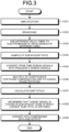
- FIG. 3 is a flowchart illustrating the operation of the data compression apparatus 100 according to the first embodiment.
- the antenna 110 and the amplifier 121 in the preceding stage are also illustrated.
- the operation of the amplifier 121 in the preceding stage of the data compression apparatus 100 is included.
- the data compression apparatus 100 includes the MCS receiver 120 and the MCS encoder 130.
- the MCS receiver 120 includes delay time addition units 122-2 to 122-4 and sub-ADCs 123-1 to 123-4.
- the MCS encoder 130 includes sub-fast Fourier transforms (FFTs) 131-1 to 131-4, signal processing units 132-1 to 132-4, a target frequency estimator 133, and an encoding unit 134.
- FFTs sub-fast Fourier transforms
- the amplifier 121 amplifies a target signal that is an electromagnetic wave signal received by the antenna 110 (step S101).
- the MCS receiver 120 branches the target signal amplified by the amplifier 121 into four lines, that is, four signals (step S102).
- the delay time addition units 122-2 to 122-4 add different delay times to the signals, based on the signal in the line output from the amplifier 121 to the sub-ADC 123-1 (step S103).
- the delay time addition units 122-2 to 122-4 may each add a different delay time using a delay element, or may each add a different delay time using a track-and-hold circuit.
- the delay time addition units 122-2 to 122-4 are collectively referred to as a delay time addition unit 122.
- the delay time addition unit 122 adds different delay times to different signals obtained by branching a target signal into a plurality of lines.
- the delay time addition unit 122 may be configured to be able to add a delay time also to a signal in the line output from the amplifier 121 to the sub-ADC 123-1. In this case, the delay time addition unit 122 adds a delay time of zero to the signal in the line output from the amplifier 121 to the sub-ADC 123-1.
- Each of the sub-ADCs 123-1 to 123-4 independently performs sampling at a sampling rate that is a sub-Nyquist rate of 1/20 of the Nyquist rate.
- the sub-ADC 123-1 samples the signal output from the amplifier 121.
- the sub-ADC 123-2 samples the target signal in the line output from the delay time addition unit 122-2.
- the sub-ADC 123-3 samples the target signal in the line output from the delay time addition unit 122-3.
- the sub-ADC 123-4 samples the target signal in the line output from the delay time addition unit 122-4 (step S104).
- the sub-ADCs 123-1 to 123-4 are collectively referred to as a sub-ADC 123.
- the sub-ADC 123 is a sub-sampling unit that samples signals at a sampling rate less than the Nyquist rate and outputs sampling sequences.
- the sub-FFTs 131-1 to 131-4 perform processing to convert the sampling sequences sub-Nyquist sampled by the corresponding sub-ADCs 123-1 to 123-4 into signals folded in the frequency domain.
- the sub-FFT 131-1 converts the sampling sequence from the sub-ADC 123-1 from a time-domain signal into a frequency-domain signal.
- the sub-FFT 131-2 converts the sampling sequence from the sub-ADC 123-2 from a time-domain signal into a frequency-domain signal.
- the sub-FFT 131-3 converts the sampling sequence from the sub-ADC 123-3 from a time-domain signal into a frequency-domain signal.
- the sub-FFT 131-4 converts the sampling sequence from the sub-ADC 123-4 from a time-domain signal into a frequency-domain signal (step S105).
- the sub-FFTs 131-1 to 131-4 are collectively referred to as a sub-FFT 131.
- the sub-FFT 131 is a time-frequency transform unit that converts sampling sequences in different lines from time-domain signals into frequency-domain signals.
- the signal processing units 132-1 to 132-4 multiply the frequency-domain signals converted by the corresponding sub-FFTs 131-1 to 131-4 by coefficients for phase compensation for individual sub-Nyquist zones of the number of sub-Nyquist folds K corresponding to twenty, the ratio between the sub-Nyquist rate and the Nyquist rate, and to cancel phase rotation due to the delay time differences (step S106). As illustrated in FIG.
- the coefficients are C 1, k by which the signal processing unit 132-1 multiplies the frequency-domain signal from the sub-FFT 131-1, C 2, k by which the signal processing unit 132-2 multiplies the frequency-domain signal from the sub-FFT 131-2, C 3, k by which the signal processing unit 132-3 multiplies the frequency-domain signal from the sub-FFT 131-3, and C 4, k by which the signal processing unit 132-4 multiplies the frequency-domain signal from the sub-FFT 131-4.
- k 1, 2,..., K.
- the signal processing units 132-1 to 132-4 are collectively referred to as a signal processing unit 132.
- the signal processing unit 132 performs, at one time, phase compensation processing for the sub-Nyquist zones of sampling sequences converted into frequency-domain signals, and processing to cancel phase rotation due to delay time differences between the sampling sequences.
- the target frequency estimator 133 calculates the sum total of values obtained by the multiplication by the coefficients C 1, k , C 2, k , C 3, k , and C 4, k for each sub-Nyquist zone, that is, for each identical sub-Nyquist zone number k in the signal processing units 132-1 to 132-4 (step S107).
- the target frequency estimator 133 determines a sub-Nyquist zone in which the target signal is present, that is, folded. Specifically, the target frequency estimator 133 determines that the target signal is folded in the sub-Nyquist zone in which the largest sum total is obtained (step S108). Thus, the target frequency estimator 133 determines into which sub-Nyquist zone the target signal has been folded, and estimates the frequency of the target signal.
- the encoding unit 134 converts a value representing the sub-Nyquist zone and the corresponding amplitude value into compressed data in a specified data format, and outputs the compressed data (step S109).
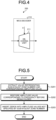
- FIG. 4 is a diagram illustrating a configuration example of the MCS decoder 210 included in the data decompression apparatus 200 according to the first embodiment.
- FIG. 5 is a flowchart illustrating the operation of the data decompression apparatus 200 according to the first embodiment.
- the MCS decoder 210 includes a decoding unit 211.
- the decoding unit 211 acquires the compressed data output from the encoding unit 134 of the data compression apparatus 100, and extracts the value representing the sub-Nyquist zone number k and the corresponding amplitude value from the compressed data (step S201).
- the decoding unit 211 restores an amplitude value corresponding to a frequency before being folded in the data compression apparatus 100, using the value representing the sub-Nyquist zone number k and the corresponding amplitude value extracted (step S202).
- the decoding unit 211 inserts zeros as component values into amplitude values corresponding to frequencies not specified by the sub-Nyquist zone number k (step S203).
- the MCS decoder 210 extracts the value representing the sub-Nyquist zone and the corresponding amplitude value from the compressed data acquired from the data compression apparatus 100, and restores the amplitude value corresponding to the frequency before the target signal is folded in the data compression apparatus 100.
- the MCS receiver 120 and the MCS encoder 130 are implemented by processing circuitry.
- the processing circuitry may be a processor that executes a program stored in memory and the memory, or may be dedicated hardware.
- the processing circuitry is also referred to as a control circuit.
- FIG. 6 is a diagram illustrating a configuration example of processing circuitry 90 when the processing circuitry included in the data compression apparatus 100 according to the first embodiment is implemented by a processor and memory.
- the processing circuitry 90 illustrated in FIG. 6 is a control circuit and includes a processor 91 and memory 92.
- the functions of the processing circuitry 90 are implemented by software, firmware, or a combination of software and firmware.
- the software or firmware is described as a program and stored in the memory 92.
- the processor 91 reads and executes the program stored in the memory 92, thereby implementing the functions.
- the processing circuitry 90 includes the memory 92 for storing the program that results in the execution of the processing in the data compression apparatus 100.
- This program can be said to be a program for causing the data compression apparatus 100 to execute the functions implemented by the processing circuitry 90.
- This program may be provided by a storage medium in which the program is stored, or may be provided by other means such as a communication medium.
- the program can be said to be a program that includes a first step of outputting, by the MCS receiver 120, sampling sequences corresponding to signals obtained by adding different delay times to different signals obtained by branching a target signal into a plurality of lines, and sampling the signals at a sampling rate less than the Nyquist rate, and a second step of converting, by the MCS encoder 130, the sampling sequences into compressed data and outputting the compressed data, and causes the data compression apparatus 100 to perform, as the second step, a third step of converting, by the sub-FFTs 131-1 to 131-4, the sampling sequences in the lines from time-domain signals into frequency-domain signals, a fourth step of performing, by the signal processing units 132-1 to 132-4, at one time, phase compensation processing for the sub-Nyquist zones of the sampling sequences converted into the frequency-domain signals, and processing to cancel phase rotation due to delay time differences between the sampling sequences, a fifth step of determining, by the target frequency estimator 133, into which sub-Nyquist
- the processor 91 is, for example, a central processing unit (CPU), a processing unit, an arithmetic unit, a microprocessor, a microcomputer, a digital signal processor (DSP), or the like.
- the memory 92 corresponds, for example, to nonvolatile or volatile semiconductor memory such as random-access memory (RAM), read-only memory (ROM), flash memory, an erasable programmable ROM (EPROM), or an electrically EPROM (EEPROM) (registered trademark), or a magnetic disk, a flexible disk, an optical disk, a compact disk, a mini disk, a digital versatile disc (DVD), or the like.
- RAM random-access memory
- ROM read-only memory
- EPROM erasable programmable ROM
- EEPROM electrically EPROM
- DVD digital versatile disc
- FIG. 7 is a diagram illustrating an example of processing circuitry 93 when dedicated hardware constitutes the processing circuitry included in the data compression apparatus 100 according to the first embodiment.
- the processing circuitry 93 illustrated in FIG. 7 corresponds, for example, to a single circuit, a combined circuit, a programmed processor, a parallel-programmed processor, an application-specific integrated circuit (ASIC), a fieldprogrammable gate array (FPGA), or a combination of them.
- the processing circuitry may be implemented partly by dedicated hardware and partly by software or firmware.
- the processing circuitry can implement the above-described functions by dedicated hardware, software, firmware, or a combination of them.
- the hardware configuration of the data compression apparatus 100 has been described.
- the hardware configuration of the data decompression apparatus 200 is the same as the hardware configuration of the data compression apparatus 100.
- the MCS receiver 120 adds different delay times to different signals obtained by branching a target signal into a plurality of lines, and outputs sampling sequences obtained by sampling the signals at a sampling rate less than the Nyquist rate.
- the MCS encoder 130 converts the sampling sequences in the lines from time-domain signals into frequency-domain signals, and performs, at one time, phase compensation processing for the sub-Nyquist zones of the sampling sequences converted into the frequency-domain signals, and processing to cancel phase rotation due to delay time differences between the sampling sequences.
- the MCS encoder 130 determines into which sub-Nyquist zone the target signal has been folded, estimates the frequency of the target signal, converts a value representing the sub-Nyquist zone and the corresponding amplitude value into compressed data in a specified data format, and outputs the compressed data. Consequently, when outputting a target signal to the data decompression apparatus 200, the data compression apparatus 100 can improve the compression ratio of a sparse signal while reducing an increase in computational load.
- a second embodiment describes a case where a data compression apparatus applies Hann windows to time-series data, that is, output signals sub-Nyquist sampled by the sub-ADCs 123-1 to 123-4.
- FIG. 8 is a diagram illustrating a configuration example of a data compression apparatus 100a according to the second embodiment.
- FIG. 9 is a flowchart illustrating the operation of the data compression apparatus 100a according to the second embodiment.
- the data compression apparatus 100a includes the MCS receiver 120 and an MCS encoder 130a.
- the MCS encoder 130a is obtained by adding window processing units 135-1 to 135-4 to the MCS encoder 130 of the first embodiment illustrated in FIG. 2 .
- step S104 the operation up to step S104 is the same as the operation of the data compression apparatus 100 in the first embodiment.
- the window processing units 135-1 to 135-4 multiply the sampling sequences sub-Nyquist sampled by the corresponding sub-ADCs 123-1 to 123-4 by coefficients corresponding to the Hann windows (step S111). As illustrated in FIG.
- the coefficients are W 1, 1 by which the window processing unit 135-1 multiplies the sampling sequence from the sub-ADC 123-1, W 2, 1 by which the window processing unit 135-2 multiplies the sampling sequence from the sub-ADC 123-2, W 3, 1 by which the window processing unit 135-3 multiplies the sampling sequence from the sub-ADC 123-3, and W 4, 1 by which the window processing unit 135-4 multiplies the sampling sequence from the sub-ADC 123-4.
- l 1, 2,..., K.
- the window processing units 135-1 to 135-4 are collectively referred to as a window processing unit 135.
- the window processing unit 135 multiplies sampling sequences in the lines output from the MCS receiver 120 by coefficients corresponding to the Hann windows.
- the window processing unit 135 outputs the sampling sequences in the lines multiplied by the coefficients corresponding to the Hann windows to the sub-FFT 131.
- the sub-FFTs 131-1 to 131-4 convert the sampling sequences multiplied by the coefficients corresponding to the Hann windows by the corresponding window processing units 135-1 to 135-4, that is, the sampling sequences in the lines output from the window processing unit 135 from time-domain signals into frequency-domain signals (step S105). That is, the sub-FFTs 131-1 to 131-4 perform processing to convert the sampling sequences output from the corresponding window processing units 135-1 to 135-4 into signals folded in the frequency domain.
- the operation in after step S106 is the same as the operation of the data compression apparatus 100 in the first embodiment.
- FIG. 10 is a diagram illustrating an example of a spectrogram as a comparative example.
- the horizontal axis represents time
- the vertical axis represents frequency
- differences in shades of color in the graph represent amplitude absolute values.
- the spectrogram illustrated in FIG. 10 is obtained when a data compression apparatus of the comparative example receives a signal on which a continuous wave (CW) signal, a pulse signal, and a chirp signal are superimposed, performs sampling at a sampling rate equal to the Nyquist rate, and performs signal processing by an FFT.
- CW continuous wave
- FIG. 11 is a diagram illustrating an example of a spectrogram obtained through encoding and decoding by a data compression system consisting of the data compression apparatus 100a illustrated in FIG. 8 and the data decompression apparatus 200 illustrated in FIG. 4 .
- the horizontal axis represents time
- the vertical axis represents frequency
- differences in shades of color in the graph represent amplitude absolute values.
- a comparison between FIG. 10 and FIG. 11 shows that the spectrogram obtained by the data compression system consisting of the data compression apparatus 100a illustrated in FIG. 8 and the data decompression apparatus 200 illustrated in FIG. 4 has a high degree of coincidence with the spectrogram of the comparative example obtained when sampling is performed at the sampling rate equal to the Nyquist rate and signal processing is performed by the FFT.
- the MCS receiver 120 and the MCS encoder 130a are implemented by processing circuitry.
- the processing circuitry may be a processor that executes a program stored in memory and the memory, or may be dedicated hardware.
- the MCS encoder 130a performs window processing on sampling sequences. Consequently, compared with the first embodiment, the data compression apparatus 100a reduces side lobes in a spectrogram to be compressed and increases sparsity, and thus can compress data more effectively.
- the MCS encoder 130 of the data compression apparatus 100 in the first embodiment performs processing only on sub-Nyquist zones in which a valid signal can be present.
- the data compression apparatus 100 uses a target signal that is an electromagnetic wave signal received by the antenna 110 and amplified by the amplifier 121.
- the fractional bandwidth of the antenna 110 is, for example, only about 0.5, and a valid signal can be present in limited sub-Nyquist zones of the K sub-Nyquist zones. Therefore, the MCS encoder 130 can perform the signal processing on limited sub-Nyquist zones, according to the characteristics of the antenna 110.
- the MCS encoder 130 performs the signal processing only on sub-Nyquist zones of the K sub-Nyquist zones in which a valid signal can be present. Consequently, the data compression apparatus 100 can reduce the processing load of the signal processing.
- the MCS encoder 130a of the data compression apparatus 100a in the second embodiment performs the signal processing only on sub-Nyquist zones in which a valid signal can be present.
- the data compression apparatus 100a uses a target signal that is an electromagnetic wave signal received by the antenna 110 and amplified by the amplifier 121.
- the fractional bandwidth of the antenna 110 is, for example, only about 0.5, and a valid signal can be present in limited sub-Nyquist zones of the K sub-Nyquist zones. Therefore, the MCS encoder 130a can perform the signal processing on limited sub-Nyquist zones, according to the characteristics of the antenna 110.
- the MCS encoder 130a performs the signal processing only on sub-Nyquist zones of the K sub-Nyquist zones in which a valid signal can be present. Consequently, the data compression apparatus 100a can reduce the processing load of the signal processing.
- the MCS receiver 120 samples a target signal branched with the sub-ADCs 123-1 to 123-4.
- an MCS receiver samples a target signal by one ADC before branching the target signal.
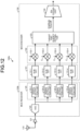
- FIG. 12 is a diagram illustrating a configuration example of a data compression apparatus 100b according to the fifth embodiment.
- FIG. 13 is a flowchart illustrating the operation of the data compression apparatus 100b according to the fifth embodiment.
- the data compression apparatus 100b includes an MCS receiver 120b and the MCS encoder 130.
- the MCS receiver 120b is a receiver that converts a target signal that is an electromagnetic wave signal received by the antenna 110 and amplified by the amplifier 121 into a plurality of sampling sequences.
- the MCS receiver 120b includes the amplifier 121, an ADC 124 as a sampling unit, and signal extraction units 125-1 to 125-4.
- the amplifier 121 amplifies a target signal that is an electromagnetic wave signal received by the antenna 110 (step S101).
- the ADC 124 of the MCS receiver 120b samples the target signal amplified by the amplifier 121 at a sampling rate of the Nyquist rate (step S121).
- the signal extraction units 125-1 to 125-4 each extract a signal corresponding to a specified delay time difference from the signal sampled by the ADC 124 to give the delay time difference to the sampling timing of the ADC 124 (step S122).
- the signal extraction units 125-1 to 125-4 are collectively referred to as a signal extraction unit 125.
- the operation of the MCS encoder 130 after that is the same as the operation of the MCS encoder 130 in the first embodiment.
- the data compression apparatus 100b may replace the MCS encoder 130 with the MCS encoder 130a of the second embodiment.
- the MCS receiver 120b and the MCS encoder 130 are implemented by processing circuitry.
- the processing circuitry may be a processor that executes a program stored in memory and the memory, or may be dedicated hardware.
- the MCS receiver 120b extracts signals corresponding to the specified delay time differences after sampling a target signal. Also in this case, the data compression apparatus 100b can obtain the same effects as the data compression apparatus 100 in the first embodiment.
- the target frequency estimator 133 takes the sum totals of values obtained by multiplication by the corresponding coefficients in the signal processing units 132-1 to 132-4, and determines that the signal is folded in a sub-Nyquist zone in which the largest sum total is obtained.
- a sixth embodiment describes a method by which the target frequency estimator 133 determines a sub-Nyquist zone in which a signal is folded by another method. The description uses the first embodiment as an example, but the method is also applicable to the second to fifth embodiments.
- FIG. 14 is a flowchart illustrating the operation of the data compression apparatus 100 according to the sixth embodiment.
- the operation from step S101 to step S106 and the operation in step S109 are the same as the operation from step S101 to step S106 and the operation in step S109 in the flowchart in the first embodiment illustrated in FIG. 3 .
- the target frequency estimator 133 checks variations in values obtained by multiplication by the coefficients C 1, k , C 2, k , C 3, k , and C 4, k for each sub-Nyquist zone, that is, for each identical sub-Nyquist zone number k in the signal processing units 132-1 to 132-4 (step S131).
- the target frequency estimator 133 determines a sub-Nyquist zone in which the target signal is folded. Specifically, the target frequency estimator 133 determines that the target signal is folded in a sub-Nyquist zone having the smallest variations (step S132).
- the MCS encoder 130 determines that a target signal is folded in a sub-Nyquist zone having the smallest variations in values obtained by multiplication by the coefficients for each sub-Nyquist zone. Also in this case, the data compression apparatus 100 can obtain the same effects as the data compression apparatus 100 of the first embodiment.
- a seventh embodiment describes a case where a data compression apparatus performs encoding processing in two stages in a data compression system.
- the description uses the first embodiment as an example, but the case is also applicable to the second to sixth embodiments.
- FIG. 15 is a diagram illustrating a configuration example of a data compression system 1c according to the seventh embodiment.
- the data compression system 1c includes a data compression apparatus 100c and a data decompression apparatus 200c.
- the data compression apparatus 100c is obtained by adding an encoder 140 to the data compression apparatus 100.
- the data decompression apparatus 200c is obtained by adding a decoder 220 to the data decompression apparatus 200.
- the encoder 140 further compresses compressed data output from the encoding unit 134 and outputs the further compressed data to the data decompression apparatus 200c.
- the encoder 140 may use, for example, entropy coding such as a Huffman code or an arithmetic code, or may use logarithmic transformation, floating-point return, or the like, or may use a combination of them.
- entropy coding such as a Huffman code or an arithmetic code
- logarithmic transformation, floating-point return, or the like or may use a combination of them.
- the MCS encoder 130 is sometimes referred to as a first encoder
- the encoder 140 is sometimes referred to as a second encoder.
- the decoder 220 decodes the compressed data acquired from the data compression apparatus 100c using a decoding scheme corresponding to an encoding scheme of the encoder 140, and outputs the decoded data to the MCS decoder 210.
- the MCS decoder 210 is sometimes referred to as a first decoder
- the decoder 220 is sometimes referred to as a second decoder.
- the MCS receiver 120, the MCS encoder 130, and the encoder 140 are implemented by processing circuitry.
- the processing circuitry may be a processor that executes a program stored in memory and the memory, or may be dedicated hardware.
- the MCS decoder 210 and the decoder 220 are implemented by processing circuitry.
- the processing circuitry may be a processor that executes a program stored in memory and the memory, or may be dedicated hardware.
- the data compression apparatus 100c includes the encoder 140 to further compress compressed data, and the data decompression apparatus 200c includes the decoder 220 to decode the compressed data compressed, that is, encoded by the encoder 140. Consequently, the data compression apparatus 100c can output compressed data compressed further than in the data compression apparatus 100 of the first embodiment.
- An eighth embodiment describes a case where a data decompression apparatus includes a storage in a data compression system.
- the description uses the first embodiment as an example, but the case is also applicable to the second to sixth embodiments.
- FIG. 16 is a diagram illustrating a configuration example of a data compression system 1d according to the eighth embodiment.
- the data compression system 1d includes the data compression apparatus 100 and a data decompression apparatus 200d.
- the data decompression apparatus 200d is obtained by adding a storage 230 to the data decompression apparatus 200.
- the storage 230 stores compressed data acquired from the data compression apparatus 100. Using the compressed data stored in the storage 230, the MCS decoder 210 restores an amplitude value corresponding to a frequency before being folded in the data compression apparatus 100.
- the data decompression apparatus 200d includes the storage 230 has been described, but the data compression apparatus 100 may also include a storage in the subsequent stage of the MCS encoder 130.
- the MCS decoder 210 and the storage 230 are implemented by processing circuitry.
- the processing circuitry may be a processor that executes a program stored in memory and the memory, or may be dedicated hardware.
- the data decompression apparatus 200d stores compressed data acquired from the data compression apparatus 100 in the storage 230 and then performs decoding. For example, if the state of communication between the data compression apparatus 100 and the data decompression apparatus 200d deteriorates, and it takes time to acquire compressed data from the data compression apparatus 100, the data decompression apparatus 200d can store compressed data in the storage 230 to store a required amount of compressed data, and then perform decoding.
- a ninth embodiment describes a case where the storage 230 is added to the data decompression apparatus 200c of the data compression system 1c in the seventh embodiment.
- FIG. 17 is a diagram illustrating a configuration example of a data compression system 1e according to the ninth embodiment.
- the data compression system 1e includes the data compression apparatus 100c and a data decompression apparatus 200e.
- the data decompression apparatus 200e is obtained by adding the storage 230 to the data decompression apparatus 200c.
- the storage 230 stores compressed data acquired from the data compression apparatus 100c.
- the decoder 220 decodes the compressed data stored in the storage 230 using a decoding scheme corresponding to an encoding scheme of the encoder 140, and outputs the decoded data to the MCS decoder 210.
- the data compression apparatus 100c may also include a storage in the subsequent stage of the encoder 140.
- the MCS decoder 210, the decoder 220, and the storage 230 are implemented by processing circuitry.
- the processing circuitry may be a processor that executes a program stored in memory and the memory, or may be dedicated hardware.
- the data decompression apparatus 200e stores compressed data acquired from the data compression apparatus 100c in the storage 230 and then performs decoding. Also in this case, the data decompression apparatus 200e can obtain the same effects as the data decompression apparatus 200d of the eighth embodiment.
- a tenth embodiment describes a case where a data decoding apparatus includes an inverse discrete Fourier transform (IDFT).
- IDFT inverse discrete Fourier transform
- FIG. 18 is a diagram illustrating a configuration example of a data compression system 1f according to the tenth embodiment.
- the data compression system 1f includes the data compression apparatus 100 and a data decompression apparatus 200f.
- the data decompression apparatus 200f is obtained by adding an IDFT 240 to the data decompression apparatus 200.
- the IDFT 240 is a frequency-time transform unit that converts a value restored by the MCS decoder 210, that is, a frequency amplitude value from a frequency-domain signal into a time-domain signal and outputs the time-domain signal.
- the MCS decoder 210 and the IDFT 240 are implemented by processing circuitry.
- the processing circuitry may be a processor that executes a program stored in memory and the memory, or may be dedicated hardware.
- the data decompression apparatus 200f converts a restored frequency amplitude value from a frequency-domain signal into a time-domain signal and outputs the time-domain signal. Consequently, the data decompression apparatus 200f can output, to an apparatus in the subsequent stage (not illustrated), decoded information in a time-domain signal form similar to that of the target signal acquired by the data compression apparatus 100.
- An eleventh embodiment describes a case where a data compression apparatus includes a plurality of antennas.
- the description uses the first embodiment as an example, but the case is also applicable to the second to tenth embodiments.
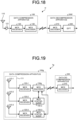
- FIG. 19 is a diagram illustrating a configuration example of a data compression system 1g according to the eleventh embodiment.
- the data compression system 1g includes a data compression apparatus 100g and the data decompression apparatus 200.
- the data compression apparatus 100g includes an array antenna element group 111 consisting of a primary antenna 110-1 and one or more secondary antennas 110-2 and 110-3, a primary MCS receiver 120-1, one or more secondary MCS receivers 120-2 and 120-3, an MCS encoder 130g, and one or more MCS synthesizers 150-2 and 150-3.
- the primary MCS receiver 120-1 is connected to the primary antenna 110-1
- the secondary MCS receiver 120-2 is connected to the secondary antenna 110-2
- the secondary MCS receiver 120-3 is connected to the secondary antenna 110-3.
- the antennas 110-1 to 110-3 have the same configuration as the above-described antenna 110.
- the MCS receivers 120-1 to 120-3 have the same configuration as the above-described MCS receiver 120.
- the antennas 110-1 to 110-3 are sometimes referred to as antennas 110 when not distinguished, and the MCS receivers 120-1 to 120-3 are sometimes referred to as MCS receivers 120 when not distinguished.
- the data compression apparatus 100g includes a plurality of MCS receivers 120, and each of the plurality of MCS receivers 120 is connected to a different antenna 110.
- the MCS receiver 120-1 is sometimes referred to as a first receiver, and the MCS receivers 120-2 and 120-3 are sometimes referred to as second receivers.
- the MCS receiver 120-1, a first receiver of the plurality of MCS receivers 120 outputs sampling sequences of a target signal received by the primary antenna 110-1.
- FIG. 20 is a diagram illustrating a configuration example of the data compression apparatus 100g according to the eleventh embodiment.
- the data compression apparatus 100g includes one secondary antenna 110-2, one secondary MCS receiver 120-2, and one MCS synthesizer 150-2 will be described.
- the MCS receiver 120-1 performs sub-Nyquist sampling on an electromagnetic wave signal received by the antenna 110-1 in a plurality of sequences in parallel.
- the MCS encoder 130g includes the sub-FFT 131, the signal processing unit 132, a target frequency estimator 133g, and an encoding unit 134g.
- the sub-FFT 131 converts the sub-Nyquist-sampled sampling sequences into signals folded in the frequency domain, and the signal processing unit 132 performs phase compensation for each sub-Nyquist zone.
- the target frequency estimator 133g calculates the sum totals of amplitude components each phase-compensated by the signal processing unit 132, and searches for a sub-Nyquist zone corresponding to one of the sum totals whose absolute value is the largest value.
- the target frequency estimator 133g outputs, to the encoding unit 134g, the value of the sum total of the amplitude components corresponding to the one whose absolute value is the largest value, and sub-Nyquist zone information that is the value of the sub-Nyquist zone corresponding to the one whose absolute value is the largest value.
- the target frequency estimator 133g outputs the sub-Nyquist zone information to the MCS synthesizer 150-2.
- the MCS receiver 120-2 performs sub-Nyquist sampling on an electromagnetic wave signal received by the antenna 110-2 in a plurality of sequences in parallel.
- the MCS synthesizer 150-2 includes the sub-FFT 131, a signal processing unit 132g, and an amplitude synthesis unit 136.
- the sub-FFT 131 converts the sub-Nyquist-sampled sampling sequences into signals folded in the frequency domain.
- the signal processing unit 132g performs phase compensation for a sub-Nyquist zone according to the sub-Nyquist zone information on a primary element line that is a line of the primary antenna 110-1 acquired from the target frequency estimator 133g of the MCS encoder 130g.
- the amplitude synthesis unit 136 calculates the sum total of amplitude components phase-compensated by the signal processing unit 132g, according to the sub-Nyquist zone information on the primary element line acquired from the target frequency estimator 133g of the MCS encoder 130g, and outputs the value of the sum total of the amplitude components to the MCS encoder 130g.
- the MCS synthesizer 150-2 is a synthesizer that is connected to a different second receiver, calculates the sum total of amplitude components corresponding to a sub-Nyquist zone, using the sub-Nyquist zone information acquired from the MCS encoder 130g, and outputs the sum total to the MCS encoder 130g.
- the MCS synthesizer 150-2 which uses the sub-Nyquist zone information acquired from the target frequency estimator 133g of the MCS encoder 130g, thus only needs to perform phase compensation for a single sub-Nyquist zone, allowing a reduction in the amount of computation to determine the sum total of amplitude components after that, and the elimination of computation to search for the largest value of absolute values. Consequently, the MCS synthesizer 150-2 allows a signal processing circuit to be reduced in size, power consumption, and cost and increased in speed, for example, as compared with the MCS encoder 130g.
- the encoding unit 134g of the MCS encoder 130g can share sub-Nyquist zone information on a secondary element line that is a line of the secondary antenna 110-2, the value of the exponent portion of a floating point, etc. with the primary element line, and thus can improve code compression efficiency.
- the encoding unit 134g which shares values between the primary element line and the secondary element line, thus has processing details different from those of the above-described encoding unit 134.
- the MCS encoder 130g is connected to the MCS receiver 120-1, and outputs the sub-Nyquist zone information on the sampling sequences of the target signal received by the primary antenna 110-1. Using the sum total of the amplitude components acquired from the MCS synthesizer 150-2, the MCS encoder 130g outputs compressed data obtained by compressing the sampling sequences of the target signal received by the primary antenna 110-1 and the secondary antenna 110-2.
- the data compression apparatus 100g can obtain the same effects.
- the distance between the primary antenna 110-1 and the secondary antennas 110-2 and 110-3 is about 1000 m or less, the data compression apparatus 100g can obtain favorable characteristics.
- a track-and-hold circuit may be used as described above, or sampling data may be thinned out at a sub-Nyquist rate from an ADC at the Nyquist rate. It is only required that sub-Nyquist sampling can be performed in different phases in parallel.
- the MCS receivers 120-2 and 120-3 of the secondary element lines and the MCS receiver 120-1 of the primary element line may be equal or different in phase difference or delay time difference in sub-Nyquist sampling, and may be equal or unequal in the number of parallel sub-Nyquist sampling sequences.
- the MCS synthesizers 150-2 and 150-3 of the secondary element lines can perform phase compensation for the sub-Nyquist zone in the primary element line and the respective phase differences or delay time differences of the parallel sub-Nyquist sampling sequences in the secondary element lines.
- the data compression apparatus 100g can obtain the same effects by the same processing.
- the MCS encoder 130g may output, in addition to the value of a sub-Nyquist zone corresponding to a one whose absolute value takes the largest value, the values of a relatively small number of sub-Nyquist zones corresponding to a one whose absolute value is the largest next to the largest value and a one the largest next to that, that is, ones whose absolute values are the second largest and below. From the MCS encoder 130g, the MCS synthesizers 150-2 and 150-3 of the secondary element lines acquire the values of the relatively small number of sub-Nyquist zones corresponding to the ones whose absolute values are the second largest and below, thereby performing phase compensation for the relatively small number of sub-Nyquist zones.
- the MCS synthesizers 150-2 and 150-3 of the secondary element lines may calculate the sum totals of amplitude components each phase-compensated, search for a sub-Nyquist zone corresponding to one of the sum totals whose absolute value takes the largest value, and output the value of the sum total of the amplitude components corresponding to the one whose absolute value takes the largest value. Consequently, the data compression apparatus 100g can also balance the amounts of computation, compression accuracy, etc. between the MCS encoder 130g and the MCS synthesizers 150-2 and 150-3.
- FIG. 21 is a flowchart illustrating the operation of the data compression apparatus 100g according to the eleventh embodiment.
- the operation from step S101 to step S108 is the same as the operation of the data compression apparatus 100 in the first embodiment.
- the target frequency estimator 133g outputs sub-Nyquist zone information to the MCS synthesizer 150-2 (step S141).
- the amplitude synthesis unit 136 calculates the sum total of amplitude components in the secondary element line phase-compensated by the signal processing unit 132g, according to the sub-Nyquist zone information on the primary element line acquired from the target frequency estimator 133g (step S142).
- the amplitude synthesis unit 136 outputs the value of the sum total of the amplitude components to the encoding unit 134g. Based on the information acquired from the target frequency estimator 133g and the amplitude synthesis unit 136, the encoding unit 134g converts a value representing the sub-Nyquist zone and the corresponding amplitude values into compressed data in a specified data format and outputs the compressed data (step S143).
- FIG. 22 is a flowchart illustrating the operation of the data decompression apparatus 200 according to the eleventh embodiment.
- the decoding unit 211 acquires the compressed data output from the encoding unit 134g of the data compression apparatus 100g, and extracts, from the compressed data, the value representing the sub-Nyquist zone number k and the same number of the corresponding amplitude values as the number of the antennas 110 (step S211). Using the value representing the sub-Nyquist zone number k and the same number of the corresponding amplitude values as the number of the antennas 110 extracted, the decoding unit 211 restores the same number of amplitude values as the number of the antennas 110 corresponding to frequencies before being folded in the data compression apparatus 100 (step S212).
- the decoding unit 211 inserts zeros as component values into amplitude values corresponding to frequencies not specified by the sub-Nyquist zone number k (step S203). Thus, the decoding unit 211 is different in processing details from the above-described decoding unit 211.
- the eighth embodiment has described the case where the data decompression apparatus 200d includes the storage 230
- the ninth embodiment has described the case where the data decompression apparatus 200e includes the storage 230.
- a data compression apparatus may include a storage as described above.
- FIG. 23 is a first diagram illustrating a configuration example of a data compression system 1h according to a twelfth embodiment.
- the data compression system 1h includes a data compression apparatus 100h and the data decompression apparatus 200.
- the data compression apparatus 100h is obtained by adding a storage 160 to the data compression apparatus 100.
- the storage 160 stores compressed data output from the MCS encoder 130.
- the data compression apparatus 100h can also store compressed data converted by the MCS encoder 130 in the storage 160 and then output the compressed data to the data decompression apparatus 200.
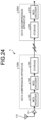
- FIG. 24 is a second diagram illustrating a configuration example of a data compression system 1i according to the twelfth embodiment.
- the data compression system 1i includes the data compression apparatus 100h and the data decompression apparatus 200d.
- the data compression system 1i may have the configuration in which the data compression apparatus 100h includes the storage 160, and the data decompression apparatus 200d includes the storage 230.
- 1, 1c, 1d, 1e, 1f, 1g, 1h, 1i data compression system 100, 100a, 100b, 100c, 100g, 100h data compression apparatus; 110, 110-1 to 110-3 antenna; 111 array antenna element group; 120, 120b, 120-1 to 120-3 MCS receiver; 121 amplifier; 122, 122-2 to 122-4 delay time addition unit; 123, 123-1 to 123-4 sub-ADC; 124 ADC; 125, 125-1 to 125-4 signal extraction unit; 130, 130a, 130g MCS encoder; 131, 131-1 to 131-4 sub-FFT; 132, 132-1 to 132-4, 132g signal processing unit; 133, 133g target frequency estimator; 134, 134g encoding unit; 135, 135-1 to 135-4 window processing unit; 136 amplitude synthesis unit; 140 encoder; 150-2, 150-3 MCS synthesizer; 200, 200c, 200d, 200e, 200f data decompression apparatus; 210 MCS decoder;
Landscapes
- Engineering & Computer Science (AREA)
- Computer Networks & Wireless Communication (AREA)
- Physics & Mathematics (AREA)
- Signal Processing (AREA)
- Electromagnetism (AREA)
- Quality & Reliability (AREA)
- Radar, Positioning & Navigation (AREA)
- Remote Sensing (AREA)
- General Physics & Mathematics (AREA)
- Theoretical Computer Science (AREA)
- Compression, Expansion, Code Conversion, And Decoders (AREA)
Abstract
Description
- The present disclosure relates to a data compression apparatus that compresses data, a data decompression apparatus, a data compression system, a control circuit, a storage medium, a data compression method, and a data decompression method.
- In general, a sparse signal with many component values whose magnitudes can be represented by zero or values small enough to be regarded as zero by selecting a proper basis can be efficiently represented by the values of a small number of components that are not regarded as zero under the selected basis. A technique using compressed sensing is considered as a method using this characteristic to convert sampling sequence data obtained by sampling a sparse signal with an analog-to-digital converter (ADC) into a compressed data format based on the values of a small number of components that are not regarded as zero.
- For example, Patent Literature 1 discloses a technique called sparse reconstruction to represent a sparse signal with fewer variables by iteratively optimizing the fidelity and sparsity of compressed representation.
- Patent Literature 1:
Japanese Patent No. 6038981 - However, the above conventional technique has a very large computational load in optimization processing to search for a combination of a proper basis and its component values in compressed sensing. For example, there is a problem that processing of a broadband signal with 1 GS/s or more is impractical.
- The present disclosure has been made in view of the above, and an object thereof is to provide a data compression apparatus capable of improving the compression ratio of a sparse signal while reducing an increase in computational load.
- To solve the problem and achieve the object described above, a data compression apparatus according to the present disclosure includes a receiver to output sampling sequences corresponding to signals obtained by adding different delay times to different signals obtained by branching a target signal into a plurality of lines, and sampling the signals at a sampling rate less than a Nyquist rate, and an encoder to convert the sampling sequences into compressed data and output the compressed data. The encoder includes a time-frequency transform unit to convert the sampling sequences in the lines from time-domain signals into frequency-domain signals, a signal processing unit to perform, at one time, phase compensation processing for sub-Nyquist zones of the sampling sequences converted into the frequency-domain signals, and processing to cancel phase rotation due to delay time differences between the sampling sequences, a target frequency estimator to determine into which sub-Nyquist zone the target signal has been folded and estimate a frequency of the target signal, and an encoding unit to convert a value representing the sub-Nyquist zone and a corresponding amplitude value into the compressed data in a specified data format and output the compressed data.
- The data compression apparatus according to the present disclosure has the effect of being able to improve the compression ratio of a sparse signal while reducing an increase in computational load.
-
-
FIG. 1 is a diagram illustrating a configuration example of a data compression system according to a first embodiment. -
FIG. 2 is a diagram illustrating a configuration example of a data compression apparatus according to the first embodiment. -
FIG. 3 is a flowchart illustrating the operation of the data compression apparatus according to the first embodiment. -
FIG. 4 is a diagram illustrating a configuration example of a multi-coset sampling (MCS) decoder included in a data decompression apparatus according to the first embodiment. -
FIG. 5 is a flowchart illustrating the operation of the data decompression apparatus according to the first embodiment. -
FIG. 6 is a diagram illustrating a configuration example of processing circuitry when processing circuitry included in the data compression apparatus according to the first embodiment is implemented by a processor and memory. -
FIG. 7 is a diagram illustrating an example of processing circuitry when the processing circuitry included in the data compression apparatus according to the first embodiment is constituted by dedicated hardware. -
FIG. 8 is a diagram illustrating a configuration example of a data compression apparatus according to a second embodiment. -
FIG. 9 is a flowchart illustrating the operation of the data compression apparatus according to the second embodiment. -
FIG. 10 is a diagram illustrating an example of a spectrogram as a comparative example. -
FIG. 11 is a diagram illustrating an example of a spectrogram obtained through encoding and decoding by a data compression system consisting of the data compression apparatus illustrated inFIG. 8 and the data decompression apparatus illustrated inFIG. 4 . -
FIG. 12 is a diagram illustrating a configuration example of a data compression apparatus according to a fifth embodiment. -
FIG. 13 is a flowchart illustrating the operation of the data compression apparatus according to the fifth embodiment. -
FIG. 14 is a flowchart illustrating the operation of a data compression apparatus according to a sixth embodiment. -
FIG. 15 is a diagram illustrating a configuration example of a data compression system according to a seventh embodiment. -
FIG. 16 is a diagram illustrating a configuration example of a data compression system according to an eighth embodiment. -
FIG. 17 is a diagram illustrating a configuration example of a data compression system according to a ninth embodiment. -
FIG. 18 is a diagram illustrating a configuration example of a data compression system according to a tenth embodiment. -
FIG. 19 is a diagram illustrating a configuration example of a data compression system according to an eleventh embodiment. -
FIG. 20 is a diagram illustrating a configuration example of a data compression apparatus according to the eleventh embodiment. -
FIG. 21 is a flowchart illustrating the operation of the data compression apparatus according to the eleventh embodiment. -
FIG. 22 is a flowchart illustrating the operation of a data decompression apparatus according to the eleventh embodiment. -
FIG. 23 is a first diagram illustrating a configuration example of a data compression system according to a twelfth embodiment. -
FIG. 24 is a second diagram illustrating a configuration example of a data compression system according to the twelfth embodiment. - Hereinafter, a data compression apparatus, a data decompression apparatus, a data compression system, a control circuit, a storage medium, a data compression method, and a data decompression method according to embodiments of the present disclosure will be described in detail with reference to the drawings.
-
FIG. 1 is a diagram illustrating a configuration example of a data compression system 1 according to a first embodiment. The data compression system 1 includes adata compression apparatus 100 and adata decompression apparatus 200. - The
data compression apparatus 100 includes anMCS receiver 120 and anMCS encoder 130. In the preceding stage of thedata compression apparatus 100, anantenna 110 receives an electromagnetic wave signal. Anamplifier 121 amplifies a target signal that is an electromagnetic wave signal received by theantenna 110. In thedata compression apparatus 100, theMCS receiver 120 is a receiver that converts a target signal that is an electromagnetic wave signal received by theantenna 110 and amplified by theamplifier 121 into a plurality of sampling sequences. Specifically, theMCS receiver 120 outputs sampling sequences corresponding to signals obtained by adding different delay times to different signals obtained by branching a target signal into a plurality of lines and sampling the signals at a sampling rate less than the Nyquist rate. TheMCS encoder 130 is an encoder that converts sampling sequences converted by theMCS receiver 120 into compressed data and outputs the compressed data to thedata decompression apparatus 200. - The
data decompression apparatus 200 includes anMCS decoder 210. In thedata decompression apparatus 200, theMCS decoder 210 decodes compressed data acquired from thedata compression apparatus 100 into an amplitude value corresponding to a frequency before a target signal is folded by thedata compression apparatus 100. Here, the expression "a target signal is folded" means that when the target signal is a sparse signal, the target signal is represented by a small number of components that are not regarded as zero under a selected basis. - First, the configuration and operation of the
data compression apparatus 100 will be described.FIG. 2 is a diagram illustrating a configuration example of thedata compression apparatus 100 according to the first embodiment.FIG. 3 is a flowchart illustrating the operation of thedata compression apparatus 100 according to the first embodiment. InFIG. 2 , theantenna 110 and theamplifier 121 in the preceding stage are also illustrated. The same applies to the drawings of configuration examples of the data compression apparatus in the following embodiments. InFIG. 3 , for convenience of explanation, the operation of theamplifier 121 in the preceding stage of thedata compression apparatus 100 is included. The same applies to the flowcharts of the data compression apparatus in the following embodiments. As described above, thedata compression apparatus 100 includes theMCS receiver 120 and theMCS encoder 130. TheMCS receiver 120 includes delay time addition units 122-2 to 122-4 and sub-ADCs 123-1 to 123-4. TheMCS encoder 130 includes sub-fast Fourier transforms (FFTs) 131-1 to 131-4, signal processing units 132-1 to 132-4, atarget frequency estimator 133, and an encoding unit 134. - In the preceding stage of the
data compression apparatus 100, theamplifier 121 amplifies a target signal that is an electromagnetic wave signal received by the antenna 110 (step S101). In thedata compression apparatus 100, theMCS receiver 120 branches the target signal amplified by theamplifier 121 into four lines, that is, four signals (step S102). - The delay time addition units 122-2 to 122-4 add different delay times to the signals, based on the signal in the line output from the
amplifier 121 to the sub-ADC 123-1 (step S103). For example, the delay time addition units 122-2 to 122-4 may each add a different delay time using a delay element, or may each add a different delay time using a track-and-hold circuit. The delay time addition units 122-2 to 122-4 are collectively referred to as a delaytime addition unit 122. The delaytime addition unit 122 adds different delay times to different signals obtained by branching a target signal into a plurality of lines. The delaytime addition unit 122 may be configured to be able to add a delay time also to a signal in the line output from theamplifier 121 to the sub-ADC 123-1. In this case, the delaytime addition unit 122 adds a delay time of zero to the signal in the line output from theamplifier 121 to the sub-ADC 123-1. - Each of the sub-ADCs 123-1 to 123-4 independently performs sampling at a sampling rate that is a sub-Nyquist rate of 1/20 of the Nyquist rate. Specifically, the sub-ADC 123-1 samples the signal output from the
amplifier 121. The sub-ADC 123-2 samples the target signal in the line output from the delay time addition unit 122-2. The sub-ADC 123-3 samples the target signal in the line output from the delay time addition unit 122-3. The sub-ADC 123-4 samples the target signal in the line output from the delay time addition unit 122-4 (step S104). The sub-ADCs 123-1 to 123-4 are collectively referred to as asub-ADC 123. Thesub-ADC 123 is a sub-sampling unit that samples signals at a sampling rate less than the Nyquist rate and outputs sampling sequences. - In the
MCS encoder 130, the sub-FFTs 131-1 to 131-4 perform processing to convert the sampling sequences sub-Nyquist sampled by the corresponding sub-ADCs 123-1 to 123-4 into signals folded in the frequency domain. Specifically, the sub-FFT 131-1 converts the sampling sequence from the sub-ADC 123-1 from a time-domain signal into a frequency-domain signal. The sub-FFT 131-2 converts the sampling sequence from the sub-ADC 123-2 from a time-domain signal into a frequency-domain signal. The sub-FFT 131-3 converts the sampling sequence from the sub-ADC 123-3 from a time-domain signal into a frequency-domain signal. The sub-FFT 131-4 converts the sampling sequence from the sub-ADC 123-4 from a time-domain signal into a frequency-domain signal (step S105). The sub-FFTs 131-1 to 131-4 are collectively referred to as asub-FFT 131. Thesub-FFT 131 is a time-frequency transform unit that converts sampling sequences in different lines from time-domain signals into frequency-domain signals. - The signal processing units 132-1 to 132-4 multiply the frequency-domain signals converted by the corresponding sub-FFTs 131-1 to 131-4 by coefficients for phase compensation for individual sub-Nyquist zones of the number of sub-Nyquist folds K corresponding to twenty, the ratio between the sub-Nyquist rate and the Nyquist rate, and to cancel phase rotation due to the delay time differences (step S106). As illustrated in
FIG. 2 , the coefficients are C1, k by which the signal processing unit 132-1 multiplies the frequency-domain signal from the sub-FFT 131-1, C2, k by which the signal processing unit 132-2 multiplies the frequency-domain signal from the sub-FFT 131-2, C3, k by which the signal processing unit 132-3 multiplies the frequency-domain signal from the sub-FFT 131-3, and C4, k by which the signal processing unit 132-4 multiplies the frequency-domain signal from the sub-FFT 131-4. Here, k=1, 2,..., K. The signal processing units 132-1 to 132-4 are collectively referred to as asignal processing unit 132. Thesignal processing unit 132 performs, at one time, phase compensation processing for the sub-Nyquist zones of sampling sequences converted into frequency-domain signals, and processing to cancel phase rotation due to delay time differences between the sampling sequences. - The
target frequency estimator 133 calculates the sum total of values obtained by the multiplication by the coefficients C1, k, C2, k, C3, k, and C4, k for each sub-Nyquist zone, that is, for each identical sub-Nyquist zone number k in the signal processing units 132-1 to 132-4 (step S107). Thetarget frequency estimator 133 determines a sub-Nyquist zone in which the target signal is present, that is, folded. Specifically, thetarget frequency estimator 133 determines that the target signal is folded in the sub-Nyquist zone in which the largest sum total is obtained (step S108). Thus, thetarget frequency estimator 133 determines into which sub-Nyquist zone the target signal has been folded, and estimates the frequency of the target signal. - The encoding unit 134 converts a value representing the sub-Nyquist zone and the corresponding amplitude value into compressed data in a specified data format, and outputs the compressed data (step S109).
- Next, the configuration and operation of the
data decompression apparatus 200 will be described.FIG. 4 is a diagram illustrating a configuration example of theMCS decoder 210 included in thedata decompression apparatus 200 according to the first embodiment.FIG. 5 is a flowchart illustrating the operation of thedata decompression apparatus 200 according to the first embodiment. In thedata decompression apparatus 200, theMCS decoder 210 includes adecoding unit 211. Thedecoding unit 211 acquires the compressed data output from the encoding unit 134 of thedata compression apparatus 100, and extracts the value representing the sub-Nyquist zone number k and the corresponding amplitude value from the compressed data (step S201). Thedecoding unit 211 restores an amplitude value corresponding to a frequency before being folded in thedata compression apparatus 100, using the value representing the sub-Nyquist zone number k and the corresponding amplitude value extracted (step S202). Thedecoding unit 211 inserts zeros as component values into amplitude values corresponding to frequencies not specified by the sub-Nyquist zone number k (step S203). - Thus, the
MCS decoder 210 extracts the value representing the sub-Nyquist zone and the corresponding amplitude value from the compressed data acquired from thedata compression apparatus 100, and restores the amplitude value corresponding to the frequency before the target signal is folded in thedata compression apparatus 100. - Next, a hardware configuration of the
data compression apparatus 100 will be described. In thedata compression apparatus 100, theMCS receiver 120 and theMCS encoder 130 are implemented by processing circuitry. The processing circuitry may be a processor that executes a program stored in memory and the memory, or may be dedicated hardware. The processing circuitry is also referred to as a control circuit. -
FIG. 6 is a diagram illustrating a configuration example of processingcircuitry 90 when the processing circuitry included in thedata compression apparatus 100 according to the first embodiment is implemented by a processor and memory. Theprocessing circuitry 90 illustrated inFIG. 6 is a control circuit and includes a processor 91 andmemory 92. When the processor 91 and thememory 92 constitute theprocessing circuitry 90, the functions of theprocessing circuitry 90 are implemented by software, firmware, or a combination of software and firmware. The software or firmware is described as a program and stored in thememory 92. In theprocessing circuitry 90, the processor 91 reads and executes the program stored in thememory 92, thereby implementing the functions. That is, theprocessing circuitry 90 includes thememory 92 for storing the program that results in the execution of the processing in thedata compression apparatus 100. This program can be said to be a program for causing thedata compression apparatus 100 to execute the functions implemented by theprocessing circuitry 90. This program may be provided by a storage medium in which the program is stored, or may be provided by other means such as a communication medium. - The program can be said to be a program that includes a first step of outputting, by the MCS receiver 120, sampling sequences corresponding to signals obtained by adding different delay times to different signals obtained by branching a target signal into a plurality of lines, and sampling the signals at a sampling rate less than the Nyquist rate, and a second step of converting, by the MCS encoder 130, the sampling sequences into compressed data and outputting the compressed data, and causes the data compression apparatus 100 to perform, as the second step, a third step of converting, by the sub-FFTs 131-1 to 131-4, the sampling sequences in the lines from time-domain signals into frequency-domain signals, a fourth step of performing, by the signal processing units 132-1 to 132-4, at one time, phase compensation processing for the sub-Nyquist zones of the sampling sequences converted into the frequency-domain signals, and processing to cancel phase rotation due to delay time differences between the sampling sequences, a fifth step of determining, by the target frequency estimator 133, into which sub-Nyquist zone the target signal has been folded and estimating, by the target frequency estimator 133, the frequency of the target signal, and a sixth step of converting, by the encoding unit 134, a value representing the sub-Nyquist zone and the corresponding amplitude value into compressed data in a specified data format and outputting, by the encoding unit 134, the compressed data.
- Here, the processor 91 is, for example, a central processing unit (CPU), a processing unit, an arithmetic unit, a microprocessor, a microcomputer, a digital signal processor (DSP), or the like. The
memory 92 corresponds, for example, to nonvolatile or volatile semiconductor memory such as random-access memory (RAM), read-only memory (ROM), flash memory, an erasable programmable ROM (EPROM), or an electrically EPROM (EEPROM) (registered trademark), or a magnetic disk, a flexible disk, an optical disk, a compact disk, a mini disk, a digital versatile disc (DVD), or the like. -
FIG. 7 is a diagram illustrating an example of processingcircuitry 93 when dedicated hardware constitutes the processing circuitry included in thedata compression apparatus 100 according to the first embodiment. Theprocessing circuitry 93 illustrated inFIG. 7 corresponds, for example, to a single circuit, a combined circuit, a programmed processor, a parallel-programmed processor, an application-specific integrated circuit (ASIC), a fieldprogrammable gate array (FPGA), or a combination of them. The processing circuitry may be implemented partly by dedicated hardware and partly by software or firmware. Thus, the processing circuitry can implement the above-described functions by dedicated hardware, software, firmware, or a combination of them. - The hardware configuration of the
data compression apparatus 100 has been described. The hardware configuration of thedata decompression apparatus 200 is the same as the hardware configuration of thedata compression apparatus 100. - As described above, according to the present embodiment, in the
data compression apparatus 100, theMCS receiver 120 adds different delay times to different signals obtained by branching a target signal into a plurality of lines, and outputs sampling sequences obtained by sampling the signals at a sampling rate less than the Nyquist rate. TheMCS encoder 130 converts the sampling sequences in the lines from time-domain signals into frequency-domain signals, and performs, at one time, phase compensation processing for the sub-Nyquist zones of the sampling sequences converted into the frequency-domain signals, and processing to cancel phase rotation due to delay time differences between the sampling sequences. TheMCS encoder 130 determines into which sub-Nyquist zone the target signal has been folded, estimates the frequency of the target signal, converts a value representing the sub-Nyquist zone and the corresponding amplitude value into compressed data in a specified data format, and outputs the compressed data. Consequently, when outputting a target signal to thedata decompression apparatus 200, thedata compression apparatus 100 can improve the compression ratio of a sparse signal while reducing an increase in computational load. - A second embodiment describes a case where a data compression apparatus applies Hann windows to time-series data, that is, output signals sub-Nyquist sampled by the sub-ADCs 123-1 to 123-4.
-
FIG. 8 is a diagram illustrating a configuration example of adata compression apparatus 100a according to the second embodiment.FIG. 9 is a flowchart illustrating the operation of thedata compression apparatus 100a according to the second embodiment. Thedata compression apparatus 100a includes theMCS receiver 120 and anMCS encoder 130a. TheMCS encoder 130a is obtained by adding window processing units 135-1 to 135-4 to theMCS encoder 130 of the first embodiment illustrated inFIG. 2 . - In the
data compression apparatus 100a, the operation up to step S104 is the same as the operation of thedata compression apparatus 100 in the first embodiment. After the operation in step S104, in theMCS encoder 130a, the window processing units 135-1 to 135-4 multiply the sampling sequences sub-Nyquist sampled by the corresponding sub-ADCs 123-1 to 123-4 by coefficients corresponding to the Hann windows (step S111). As illustrated inFIG. 8 , the coefficients are W1, 1 by which the window processing unit 135-1 multiplies the sampling sequence from the sub-ADC 123-1, W2, 1 by which the window processing unit 135-2 multiplies the sampling sequence from the sub-ADC 123-2, W3, 1 by which the window processing unit 135-3 multiplies the sampling sequence from the sub-ADC 123-3, and W4, 1 by which the window processing unit 135-4 multiplies the sampling sequence from the sub-ADC 123-4. Let l=1, 2,..., K. - The window processing units 135-1 to 135-4 are collectively referred to as a
window processing unit 135. Thewindow processing unit 135 multiplies sampling sequences in the lines output from theMCS receiver 120 by coefficients corresponding to the Hann windows. Thewindow processing unit 135 outputs the sampling sequences in the lines multiplied by the coefficients corresponding to the Hann windows to thesub-FFT 131. - The sub-FFTs 131-1 to 131-4 convert the sampling sequences multiplied by the coefficients corresponding to the Hann windows by the corresponding window processing units 135-1 to 135-4, that is, the sampling sequences in the lines output from the
window processing unit 135 from time-domain signals into frequency-domain signals (step S105). That is, the sub-FFTs 131-1 to 131-4 perform processing to convert the sampling sequences output from the corresponding window processing units 135-1 to 135-4 into signals folded in the frequency domain. In thedata compression apparatus 100a, the operation in after step S106 is the same as the operation of thedata compression apparatus 100 in the first embodiment. -
FIG. 10 is a diagram illustrating an example of a spectrogram as a comparative example. InFIG. 10 , the horizontal axis represents time, the vertical axis represents frequency, and differences in shades of color in the graph represent amplitude absolute values. The spectrogram illustrated inFIG. 10 is obtained when a data compression apparatus of the comparative example receives a signal on which a continuous wave (CW) signal, a pulse signal, and a chirp signal are superimposed, performs sampling at a sampling rate equal to the Nyquist rate, and performs signal processing by an FFT. -
FIG. 11 is a diagram illustrating an example of a spectrogram obtained through encoding and decoding by a data compression system consisting of thedata compression apparatus 100a illustrated inFIG. 8 and thedata decompression apparatus 200 illustrated inFIG. 4 . InFIG. 11 , the horizontal axis represents time, the vertical axis represents frequency, and differences in shades of color in the graph represent amplitude absolute values. A comparison betweenFIG. 10 andFIG. 11 shows that the spectrogram obtained by the data compression system consisting of thedata compression apparatus 100a illustrated inFIG. 8 and thedata decompression apparatus 200 illustrated inFIG. 4 has a high degree of coincidence with the spectrogram of the comparative example obtained when sampling is performed at the sampling rate equal to the Nyquist rate and signal processing is performed by the FFT. - As for the hardware configuration of the
data compression apparatus 100a, theMCS receiver 120 and theMCS encoder 130a are implemented by processing circuitry. The processing circuitry may be a processor that executes a program stored in memory and the memory, or may be dedicated hardware. - As described above, according to the present embodiment, in the
data compression apparatus 100a, theMCS encoder 130a performs window processing on sampling sequences. Consequently, compared with the first embodiment, thedata compression apparatus 100a reduces side lobes in a spectrogram to be compressed and increases sparsity, and thus can compress data more effectively. - In a third embodiment, the
MCS encoder 130 of thedata compression apparatus 100 in the first embodiment performs processing only on sub-Nyquist zones in which a valid signal can be present. - The
data compression apparatus 100 uses a target signal that is an electromagnetic wave signal received by theantenna 110 and amplified by theamplifier 121. However, the fractional bandwidth of theantenna 110 is, for example, only about 0.5, and a valid signal can be present in limited sub-Nyquist zones of the K sub-Nyquist zones. Therefore, theMCS encoder 130 can perform the signal processing on limited sub-Nyquist zones, according to the characteristics of theantenna 110. - As described above, according to the present embodiment, in the
data compression apparatus 100, theMCS encoder 130 performs the signal processing only on sub-Nyquist zones of the K sub-Nyquist zones in which a valid signal can be present. Consequently, thedata compression apparatus 100 can reduce the processing load of the signal processing. - In a fourth embodiment, the
MCS encoder 130a of thedata compression apparatus 100a in the second embodiment performs the signal processing only on sub-Nyquist zones in which a valid signal can be present. - The
data compression apparatus 100a uses a target signal that is an electromagnetic wave signal received by theantenna 110 and amplified by theamplifier 121. However, the fractional bandwidth of theantenna 110 is, for example, only about 0.5, and a valid signal can be present in limited sub-Nyquist zones of the K sub-Nyquist zones. Therefore, the MCS encoder 130a can perform the signal processing on limited sub-Nyquist zones, according to the characteristics of theantenna 110. - As described above, according to the present embodiment, in the
data compression apparatus 100a, theMCS encoder 130a performs the signal processing only on sub-Nyquist zones of the K sub-Nyquist zones in which a valid signal can be present. Consequently, thedata compression apparatus 100a can reduce the processing load of the signal processing. - In the first to fourth embodiments, the
MCS receiver 120 samples a target signal branched with the sub-ADCs 123-1 to 123-4. In a fifth embodiment, an MCS receiver samples a target signal by one ADC before branching the target signal. -
FIG. 12 is a diagram illustrating a configuration example of adata compression apparatus 100b according to the fifth embodiment.FIG. 13 is a flowchart illustrating the operation of thedata compression apparatus 100b according to the fifth embodiment. Thedata compression apparatus 100b includes anMCS receiver 120b and theMCS encoder 130. TheMCS receiver 120b is a receiver that converts a target signal that is an electromagnetic wave signal received by theantenna 110 and amplified by theamplifier 121 into a plurality of sampling sequences. TheMCS receiver 120b includes theamplifier 121, anADC 124 as a sampling unit, and signal extraction units 125-1 to 125-4. - In the preceding stage of the
data compression apparatus 100b, theamplifier 121 amplifies a target signal that is an electromagnetic wave signal received by the antenna 110 (step S101). In thedata compression apparatus 100b, theADC 124 of theMCS receiver 120b samples the target signal amplified by theamplifier 121 at a sampling rate of the Nyquist rate (step S121). The signal extraction units 125-1 to 125-4 each extract a signal corresponding to a specified delay time difference from the signal sampled by theADC 124 to give the delay time difference to the sampling timing of the ADC 124 (step S122). The signal extraction units 125-1 to 125-4 are collectively referred to as asignal extraction unit 125. The operation of theMCS encoder 130 after that is the same as the operation of theMCS encoder 130 in the first embodiment. Thedata compression apparatus 100b may replace theMCS encoder 130 with theMCS encoder 130a of the second embodiment. - As for the hardware configuration of the
data compression apparatus 100b, theMCS receiver 120b and theMCS encoder 130 are implemented by processing circuitry. The processing circuitry may be a processor that executes a program stored in memory and the memory, or may be dedicated hardware. - As described above, according to the present embodiment, in the
data compression apparatus 100b, theMCS receiver 120b extracts signals corresponding to the specified delay time differences after sampling a target signal. Also in this case, thedata compression apparatus 100b can obtain the same effects as thedata compression apparatus 100 in the first embodiment. - In the first to fifth embodiments, the
target frequency estimator 133 takes the sum totals of values obtained by multiplication by the corresponding coefficients in the signal processing units 132-1 to 132-4, and determines that the signal is folded in a sub-Nyquist zone in which the largest sum total is obtained. A sixth embodiment describes a method by which thetarget frequency estimator 133 determines a sub-Nyquist zone in which a signal is folded by another method. The description uses the first embodiment as an example, but the method is also applicable to the second to fifth embodiments. -
FIG. 14 is a flowchart illustrating the operation of thedata compression apparatus 100 according to the sixth embodiment. In the flowchart illustrated inFIG. 14 , the operation from step S101 to step S106 and the operation in step S109 are the same as the operation from step S101 to step S106 and the operation in step S109 in the flowchart in the first embodiment illustrated inFIG. 3 . Thetarget frequency estimator 133 checks variations in values obtained by multiplication by the coefficients C1, k, C2, k, C3, k, and C4, k for each sub-Nyquist zone, that is, for each identical sub-Nyquist zone number k in the signal processing units 132-1 to 132-4 (step S131). Thetarget frequency estimator 133 determines a sub-Nyquist zone in which the target signal is folded. Specifically, thetarget frequency estimator 133 determines that the target signal is folded in a sub-Nyquist zone having the smallest variations (step S132). - As described above, according to the present embodiment, in the
data compression apparatus 100, theMCS encoder 130 determines that a target signal is folded in a sub-Nyquist zone having the smallest variations in values obtained by multiplication by the coefficients for each sub-Nyquist zone. Also in this case, thedata compression apparatus 100 can obtain the same effects as thedata compression apparatus 100 of the first embodiment. - A seventh embodiment describes a case where a data compression apparatus performs encoding processing in two stages in a data compression system. The description uses the first embodiment as an example, but the case is also applicable to the second to sixth embodiments.
-
FIG. 15 is a diagram illustrating a configuration example of adata compression system 1c according to the seventh embodiment. Thedata compression system 1c includes adata compression apparatus 100c and adata decompression apparatus 200c. Thedata compression apparatus 100c is obtained by adding an encoder 140 to thedata compression apparatus 100. Thedata decompression apparatus 200c is obtained by adding adecoder 220 to thedata decompression apparatus 200. - In the
data compression apparatus 100c, the encoder 140 further compresses compressed data output from the encoding unit 134 and outputs the further compressed data to thedata decompression apparatus 200c. The encoder 140 may use, for example, entropy coding such as a Huffman code or an arithmetic code, or may use logarithmic transformation, floating-point return, or the like, or may use a combination of them. In the following description, theMCS encoder 130 is sometimes referred to as a first encoder, and the encoder 140 is sometimes referred to as a second encoder. - In the
data decompression apparatus 200c, thedecoder 220 decodes the compressed data acquired from thedata compression apparatus 100c using a decoding scheme corresponding to an encoding scheme of the encoder 140, and outputs the decoded data to theMCS decoder 210. In the following description, theMCS decoder 210 is sometimes referred to as a first decoder, and thedecoder 220 is sometimes referred to as a second decoder. - As for the hardware configuration of the
data compression apparatus 100c, theMCS receiver 120, theMCS encoder 130, and the encoder 140 are implemented by processing circuitry. The processing circuitry may be a processor that executes a program stored in memory and the memory, or may be dedicated hardware. Likewise, as for the hardware configuration of thedata decompression apparatus 200c, theMCS decoder 210 and thedecoder 220 are implemented by processing circuitry. The processing circuitry may be a processor that executes a program stored in memory and the memory, or may be dedicated hardware. - As described above, according to the present embodiment, the
data compression apparatus 100c includes the encoder 140 to further compress compressed data, and thedata decompression apparatus 200c includes thedecoder 220 to decode the compressed data compressed, that is, encoded by the encoder 140. Consequently, thedata compression apparatus 100c can output compressed data compressed further than in thedata compression apparatus 100 of the first embodiment. - An eighth embodiment describes a case where a data decompression apparatus includes a storage in a data compression system. The description uses the first embodiment as an example, but the case is also applicable to the second to sixth embodiments.
-
FIG. 16 is a diagram illustrating a configuration example of adata compression system 1d according to the eighth embodiment. Thedata compression system 1d includes thedata compression apparatus 100 and adata decompression apparatus 200d. Thedata decompression apparatus 200d is obtained by adding astorage 230 to thedata decompression apparatus 200. - In the
data decompression apparatus 200d, thestorage 230 stores compressed data acquired from thedata compression apparatus 100. Using the compressed data stored in thestorage 230, theMCS decoder 210 restores an amplitude value corresponding to a frequency before being folded in thedata compression apparatus 100. In the example ofFIG. 16 , an example in which thedata decompression apparatus 200d includes thestorage 230 has been described, but thedata compression apparatus 100 may also include a storage in the subsequent stage of theMCS encoder 130. - As for the hardware configuration of the
data decompression apparatus 200d, theMCS decoder 210 and thestorage 230 are implemented by processing circuitry. The processing circuitry may be a processor that executes a program stored in memory and the memory, or may be dedicated hardware. - As described above, according to the present embodiment, the
data decompression apparatus 200d stores compressed data acquired from thedata compression apparatus 100 in thestorage 230 and then performs decoding. For example, if the state of communication between thedata compression apparatus 100 and thedata decompression apparatus 200d deteriorates, and it takes time to acquire compressed data from thedata compression apparatus 100, thedata decompression apparatus 200d can store compressed data in thestorage 230 to store a required amount of compressed data, and then perform decoding. - A ninth embodiment describes a case where the
storage 230 is added to thedata decompression apparatus 200c of thedata compression system 1c in the seventh embodiment. -
FIG. 17 is a diagram illustrating a configuration example of adata compression system 1e according to the ninth embodiment. Thedata compression system 1e includes thedata compression apparatus 100c and adata decompression apparatus 200e. Thedata decompression apparatus 200e is obtained by adding thestorage 230 to thedata decompression apparatus 200c. - In the
data decompression apparatus 200e, thestorage 230 stores compressed data acquired from thedata compression apparatus 100c. Thedecoder 220 decodes the compressed data stored in thestorage 230 using a decoding scheme corresponding to an encoding scheme of the encoder 140, and outputs the decoded data to theMCS decoder 210. In the example ofFIG. 17 , an example in which thedata decompression apparatus 200e includes thestorage 230 has been described, but thedata compression apparatus 100c may also include a storage in the subsequent stage of the encoder 140. - As for the hardware configuration of the
data decompression apparatus 200e, theMCS decoder 210, thedecoder 220, and thestorage 230 are implemented by processing circuitry. The processing circuitry may be a processor that executes a program stored in memory and the memory, or may be dedicated hardware. - As described above, according to the present embodiment, the
data decompression apparatus 200e stores compressed data acquired from thedata compression apparatus 100c in thestorage 230 and then performs decoding. Also in this case, thedata decompression apparatus 200e can obtain the same effects as thedata decompression apparatus 200d of the eighth embodiment. - A tenth embodiment describes a case where a data decoding apparatus includes an inverse discrete Fourier transform (IDFT). The description uses the first embodiment as an example, but the case is also applicable to the second to ninth embodiments.
-
FIG. 18 is a diagram illustrating a configuration example of adata compression system 1f according to the tenth embodiment. Thedata compression system 1f includes thedata compression apparatus 100 and adata decompression apparatus 200f. Thedata decompression apparatus 200f is obtained by adding an IDFT 240 to thedata decompression apparatus 200. - In the
data decompression apparatus 200f, the IDFT 240 is a frequency-time transform unit that converts a value restored by theMCS decoder 210, that is, a frequency amplitude value from a frequency-domain signal into a time-domain signal and outputs the time-domain signal. - As for the hardware configuration of the
data decompression apparatus 200f, theMCS decoder 210 and the IDFT 240 are implemented by processing circuitry. The processing circuitry may be a processor that executes a program stored in memory and the memory, or may be dedicated hardware. - As described above, according to the present embodiment, the
data decompression apparatus 200f converts a restored frequency amplitude value from a frequency-domain signal into a time-domain signal and outputs the time-domain signal. Consequently, thedata decompression apparatus 200f can output, to an apparatus in the subsequent stage (not illustrated), decoded information in a time-domain signal form similar to that of the target signal acquired by thedata compression apparatus 100. - An eleventh embodiment describes a case where a data compression apparatus includes a plurality of antennas. The description uses the first embodiment as an example, but the case is also applicable to the second to tenth embodiments.
-
FIG. 19 is a diagram illustrating a configuration example of adata compression system 1g according to the eleventh embodiment. Thedata compression system 1g includes adata compression apparatus 100g and thedata decompression apparatus 200. Thedata compression apparatus 100g includes an arrayantenna element group 111 consisting of a primary antenna 110-1 and one or more secondary antennas 110-2 and 110-3, a primary MCS receiver 120-1, one or more secondary MCS receivers 120-2 and 120-3, anMCS encoder 130g, and one or more MCS synthesizers 150-2 and 150-3. The primary MCS receiver 120-1 is connected to the primary antenna 110-1, the secondary MCS receiver 120-2 is connected to the secondary antenna 110-2, and the secondary MCS receiver 120-3 is connected to the secondary antenna 110-3. The antennas 110-1 to 110-3 have the same configuration as the above-describedantenna 110. The MCS receivers 120-1 to 120-3 have the same configuration as the above-describedMCS receiver 120. - In the following description, the antennas 110-1 to 110-3 are sometimes referred to as
antennas 110 when not distinguished, and the MCS receivers 120-1 to 120-3 are sometimes referred to asMCS receivers 120 when not distinguished. Thedata compression apparatus 100g includes a plurality ofMCS receivers 120, and each of the plurality ofMCS receivers 120 is connected to adifferent antenna 110. The MCS receiver 120-1 is sometimes referred to as a first receiver, and the MCS receivers 120-2 and 120-3 are sometimes referred to as second receivers. In the present embodiment, the MCS receiver 120-1, a first receiver of the plurality ofMCS receivers 120, outputs sampling sequences of a target signal received by the primary antenna 110-1. The MCS receivers 120-2 and 120-3, one or more second receivers of the plurality ofMCS receivers 120, output sampling sequences of the target signal received by the secondary antennas 110-2 and 110-3. -
FIG. 20 is a diagram illustrating a configuration example of thedata compression apparatus 100g according to the eleventh embodiment. Here, for ease of explanation, a case where thedata compression apparatus 100g includes one secondary antenna 110-2, one secondary MCS receiver 120-2, and one MCS synthesizer 150-2 will be described. - Like the
MCS receiver 120 of the first embodiment etc., the MCS receiver 120-1 performs sub-Nyquist sampling on an electromagnetic wave signal received by the antenna 110-1 in a plurality of sequences in parallel. TheMCS encoder 130g includes thesub-FFT 131, thesignal processing unit 132, atarget frequency estimator 133g, and anencoding unit 134g. As in theMCS encoder 130 of the first embodiment, in theMCS encoder 130g, thesub-FFT 131 converts the sub-Nyquist-sampled sampling sequences into signals folded in the frequency domain, and thesignal processing unit 132 performs phase compensation for each sub-Nyquist zone. In the present embodiment, thetarget frequency estimator 133g calculates the sum totals of amplitude components each phase-compensated by thesignal processing unit 132, and searches for a sub-Nyquist zone corresponding to one of the sum totals whose absolute value is the largest value. Thetarget frequency estimator 133g outputs, to theencoding unit 134g, the value of the sum total of the amplitude components corresponding to the one whose absolute value is the largest value, and sub-Nyquist zone information that is the value of the sub-Nyquist zone corresponding to the one whose absolute value is the largest value. Thetarget frequency estimator 133g outputs the sub-Nyquist zone information to the MCS synthesizer 150-2. - Like the
MCS receiver 120 of the first embodiment etc., the MCS receiver 120-2 performs sub-Nyquist sampling on an electromagnetic wave signal received by the antenna 110-2 in a plurality of sequences in parallel. The MCS synthesizer 150-2 includes thesub-FFT 131, asignal processing unit 132g, and anamplitude synthesis unit 136. As in theMCS encoder 130 of the first embodiment etc., in the MCS synthesizer 150-2, thesub-FFT 131 converts the sub-Nyquist-sampled sampling sequences into signals folded in the frequency domain. In the present embodiment, thesignal processing unit 132g performs phase compensation for a sub-Nyquist zone according to the sub-Nyquist zone information on a primary element line that is a line of the primary antenna 110-1 acquired from thetarget frequency estimator 133g of theMCS encoder 130g. Theamplitude synthesis unit 136 calculates the sum total of amplitude components phase-compensated by thesignal processing unit 132g, according to the sub-Nyquist zone information on the primary element line acquired from thetarget frequency estimator 133g of theMCS encoder 130g, and outputs the value of the sum total of the amplitude components to theMCS encoder 130g. - Thus, the MCS synthesizer 150-2 is a synthesizer that is connected to a different second receiver, calculates the sum total of amplitude components corresponding to a sub-Nyquist zone, using the sub-Nyquist zone information acquired from the
MCS encoder 130g, and outputs the sum total to theMCS encoder 130g. For the secondary antenna 110-2, the MCS synthesizer 150-2, which uses the sub-Nyquist zone information acquired from thetarget frequency estimator 133g of theMCS encoder 130g, thus only needs to perform phase compensation for a single sub-Nyquist zone, allowing a reduction in the amount of computation to determine the sum total of amplitude components after that, and the elimination of computation to search for the largest value of absolute values. Consequently, the MCS synthesizer 150-2 allows a signal processing circuit to be reduced in size, power consumption, and cost and increased in speed, for example, as compared with theMCS encoder 130g. - Furthermore, the
encoding unit 134g of theMCS encoder 130g can share sub-Nyquist zone information on a secondary element line that is a line of the secondary antenna 110-2, the value of the exponent portion of a floating point, etc. with the primary element line, and thus can improve code compression efficiency. Theencoding unit 134g, which shares values between the primary element line and the secondary element line, thus has processing details different from those of the above-described encoding unit 134. As described above, theMCS encoder 130g is connected to the MCS receiver 120-1, and outputs the sub-Nyquist zone information on the sampling sequences of the target signal received by the primary antenna 110-1. Using the sum total of the amplitude components acquired from the MCS synthesizer 150-2, theMCS encoder 130g outputs compressed data obtained by compressing the sampling sequences of the target signal received by the primary antenna 110-1 and the secondary antenna 110-2. - Even when there is a plurality of secondary antennas 110-2 and 110-3, the
data compression apparatus 100g can obtain the same effects. The shorter the distance between the primary antenna 110-1 and the secondary antennas 110-2 and 110-3, the stronger the correlation between a signal in the primary element line and signals in the secondary element lines, and the better the compression accuracy becomes. For example, if the distance between the primary antenna 110-1 and the secondary antennas 110-2 and 110-3 is about 1000 m or less, thedata compression apparatus 100g can obtain favorable characteristics. - For the circuit configuration of the MCS receivers 120-1 to 120-3 that perform sub-Nyquist sampling, for example, a track-and-hold circuit may be used as described above, or sampling data may be thinned out at a sub-Nyquist rate from an ADC at the Nyquist rate. It is only required that sub-Nyquist sampling can be performed in different phases in parallel.
- The MCS receivers 120-2 and 120-3 of the secondary element lines and the MCS receiver 120-1 of the primary element line may be equal or different in phase difference or delay time difference in sub-Nyquist sampling, and may be equal or unequal in the number of parallel sub-Nyquist sampling sequences. In either case, the MCS synthesizers 150-2 and 150-3 of the secondary element lines can perform phase compensation for the sub-Nyquist zone in the primary element line and the respective phase differences or delay time differences of the parallel sub-Nyquist sampling sequences in the secondary element lines.
- Even when the number of secondary antennas 110-2 and 110-3 is two or more, the
data compression apparatus 100g can obtain the same effects by the same processing. - The
MCS encoder 130g may output, in addition to the value of a sub-Nyquist zone corresponding to a one whose absolute value takes the largest value, the values of a relatively small number of sub-Nyquist zones corresponding to a one whose absolute value is the largest next to the largest value and a one the largest next to that, that is, ones whose absolute values are the second largest and below. From theMCS encoder 130g, the MCS synthesizers 150-2 and 150-3 of the secondary element lines acquire the values of the relatively small number of sub-Nyquist zones corresponding to the ones whose absolute values are the second largest and below, thereby performing phase compensation for the relatively small number of sub-Nyquist zones. The MCS synthesizers 150-2 and 150-3 of the secondary element lines may calculate the sum totals of amplitude components each phase-compensated, search for a sub-Nyquist zone corresponding to one of the sum totals whose absolute value takes the largest value, and output the value of the sum total of the amplitude components corresponding to the one whose absolute value takes the largest value. Consequently, thedata compression apparatus 100g can also balance the amounts of computation, compression accuracy, etc. between theMCS encoder 130g and the MCS synthesizers 150-2 and 150-3. -
FIG. 21 is a flowchart illustrating the operation of thedata compression apparatus 100g according to the eleventh embodiment. InFIG. 21 , the operation from step S101 to step S108 is the same as the operation of thedata compression apparatus 100 in the first embodiment. Thetarget frequency estimator 133g outputs sub-Nyquist zone information to the MCS synthesizer 150-2 (step S141). Theamplitude synthesis unit 136 calculates the sum total of amplitude components in the secondary element line phase-compensated by thesignal processing unit 132g, according to the sub-Nyquist zone information on the primary element line acquired from thetarget frequency estimator 133g (step S142). Theamplitude synthesis unit 136 outputs the value of the sum total of the amplitude components to theencoding unit 134g. Based on the information acquired from thetarget frequency estimator 133g and theamplitude synthesis unit 136, theencoding unit 134g converts a value representing the sub-Nyquist zone and the corresponding amplitude values into compressed data in a specified data format and outputs the compressed data (step S143). -
FIG. 22 is a flowchart illustrating the operation of thedata decompression apparatus 200 according to the eleventh embodiment. Thedecoding unit 211 acquires the compressed data output from theencoding unit 134g of thedata compression apparatus 100g, and extracts, from the compressed data, the value representing the sub-Nyquist zone number k and the same number of the corresponding amplitude values as the number of the antennas 110 (step S211). Using the value representing the sub-Nyquist zone number k and the same number of the corresponding amplitude values as the number of theantennas 110 extracted, thedecoding unit 211 restores the same number of amplitude values as the number of theantennas 110 corresponding to frequencies before being folded in the data compression apparatus 100 (step S212). Thedecoding unit 211 inserts zeros as component values into amplitude values corresponding to frequencies not specified by the sub-Nyquist zone number k (step S203). Thus, thedecoding unit 211 is different in processing details from the above-describeddecoding unit 211. - The eighth embodiment has described the case where the
data decompression apparatus 200d includes thestorage 230, and the ninth embodiment has described the case where thedata decompression apparatus 200e includes thestorage 230. A data compression apparatus may include a storage as described above. -
FIG. 23 is a first diagram illustrating a configuration example of adata compression system 1h according to a twelfth embodiment. Thedata compression system 1h includes adata compression apparatus 100h and thedata decompression apparatus 200. Thedata compression apparatus 100h is obtained by adding astorage 160 to thedata compression apparatus 100. Thestorage 160 stores compressed data output from theMCS encoder 130. Thus, thedata compression apparatus 100h can also store compressed data converted by theMCS encoder 130 in thestorage 160 and then output the compressed data to thedata decompression apparatus 200. -
FIG. 24 is a second diagram illustrating a configuration example of adata compression system 1i according to the twelfth embodiment. Thedata compression system 1i includes thedata compression apparatus 100h and thedata decompression apparatus 200d. Thedata compression system 1i may have the configuration in which thedata compression apparatus 100h includes thestorage 160, and thedata decompression apparatus 200d includes thestorage 230. - The configurations described in the above embodiments illustrate an example and can be combined with another known art. The embodiments can be combined with each other. The configurations can be partly omitted or changed without departing from the gist.
- 1, 1c, 1d, 1e, 1f, 1g, 1h, 1i data compression system; 100, 100a, 100b, 100c, 100g, 100h data compression apparatus; 110, 110-1 to 110-3 antenna; 111 array antenna element group; 120, 120b, 120-1 to 120-3 MCS receiver; 121 amplifier; 122, 122-2 to 122-4 delay time addition unit; 123, 123-1 to 123-4 sub-ADC; 124 ADC; 125, 125-1 to 125-4 signal extraction unit; 130, 130a, 130g MCS encoder; 131, 131-1 to 131-4 sub-FFT; 132, 132-1 to 132-4, 132g signal processing unit; 133, 133g target frequency estimator; 134, 134g encoding unit; 135, 135-1 to 135-4 window processing unit; 136 amplitude synthesis unit; 140 encoder; 150-2, 150-3 MCS synthesizer; 200, 200c, 200d, 200e, 200f data decompression apparatus; 210 MCS decoder; 211 decoding unit; 220 decoder; 160, 230 storage; 240 IDFT.
Claims (21)
- A data compression apparatus comprising:a receiver to output sampling sequences corresponding to signals obtained by adding different delay times to different signals obtained by branching a target signal into a plurality of lines, and sampling the signals at a sampling rate less than a Nyquist rate; andan encoder to convert the sampling sequences into compressed data and output the compressed data,the encoder includinga time-frequency transform unit to convert the sampling sequences in the lines from time-domain signals into frequency-domain signals,a signal processing unit to perform, at one time, phase compensation processing for sub-Nyquist zones of the sampling sequences converted into the frequency-domain signals, and processing to cancel phase rotation due to delay time differences between the sampling sequences,a target frequency estimator to determine into which sub-Nyquist zone the target signal has been folded and estimate a frequency of the target signal, andan encoding unit to convert a value representing the sub-Nyquist zone and a corresponding amplitude value into the compressed data in a specified data format and output the compressed data.
- The data compression apparatus according to claim 1, whereinthe receiver includesa delay time addition unit to add the different delay times to the different signals obtained by branching the target signal into the plurality of lines, anda sub-sampling unit to sample the signals at the sampling rate less than the Nyquist rate and output the sampling sequences.
- The data compression apparatus according to claim 2, wherein
the delay time addition unit adds the delay times using a delay element or a track-and-hold circuit. - The data compression apparatus according to claim 1, whereinthe receiver includesa sampling unit to sample the target signal at a sampling rate of the Nyquist rate, anda signal extraction unit to extract signals corresponding to specified delay time differences from a signal sampled by the sampling unit.
- The data compression apparatus according to any one of claims 1 to 4, whereinthe encoder further includesa window processing unit to multiply the sampling sequences in the lines output from the receiver by coefficients corresponding to Hann windows, andthe time-frequency transform unit converts the sampling sequences in the lines output from the window processing unit from time-domain signals into frequency-domain signals.
- The data compression apparatus according to any one of claims 1 to 5, wherein
the encoder performs processing only on sub-Nyquist zones in which a valid signal can be present. - The data compression apparatus according to any one of claims 1 to 6, wherein
the target frequency estimator calculates a sum total of values obtained by multiplication by coefficients for each sub-Nyquist zone in the signal processing unit, and determines that the target signal is folded in a sub-Nyquist zone in which the largest sum total is obtained. - The data compression apparatus according to any one of claims 1 to 6, wherein
the target frequency estimator determines that the target signal is folded in a sub-Nyquist zone having the smallest variations in values obtained by multiplication by coefficients for each sub-Nyquist zone in the signal processing unit. - The data compression apparatus according to any one of claims 1 to 8, whereinthe encoder is a first encoder, andthe data compression apparatus further comprises a second encoder to compress the compressed data output from the first encoder.
- The data compression apparatus according to any one of claims 1 to 9, whereinthe data compression apparatus comprises a plurality of the receivers, each of the plurality of receivers being connected to a different antenna,a first receiver of the plurality of receivers outputs the sampling sequences of the target signal received by a primary antenna,one or more second receivers of the plurality of receivers output the sampling sequences of the target signal received by secondary antennas,the data compression apparatus further comprises one or more synthesizers connected to the corresponding second receivers, to calculate a sum total of amplitude components corresponding to a sub-Nyquist zone, using information on the sub-Nyquist zone acquired from the encoder, and output the sum total of the amplitude components to the encoder, andthe encoder is connected to the first receiver, outputs the information on the sub-Nyquist zone of the sampling sequences of the target signal received by the primary antenna, and outputs the compressed data obtained by compressing the sampling sequences of the target signal received by the primary antenna and the secondary antennas, using the sum totals of the amplitude components acquired from the synthesizers.
- A data decompression apparatus comprising
a decoder to extract the value representing the sub-Nyquist zone and the corresponding amplitude value from the compressed data acquired from the data compression apparatus according to any one of claims 1 to 8 and 10, and restore an amplitude value corresponding to a frequency before the target signal is folded in the data compression apparatus. - The data decompression apparatus according to claim 11, whereinthe decoder is a first decoder, andthe data decompression apparatus further comprises a second decoder to decode the compressed data acquired from the data compression apparatus according to claim 9.
- The data decompression apparatus according to claim 11 or 12, further comprising
a storage to store the compressed data acquired from the data compression apparatus. - The data decompression apparatus according to any one of claims 11 to 13, further comprising
a frequency-time transform unit to convert the value restored by the decoder from a frequency-domain signal into a time-domain signal. - A data compression system comprising:the data compression apparatus according to any one of claims 1 to 8 and 10; andthe data decompression apparatus according to claim 11.
- A control circuit to control a data compression apparatus, the control circuit causing the data compression apparatus to perform:outputting sampling sequences corresponding to signals obtained by adding different delay times to different signals obtained by branching a target signal into a plurality of lines, and sampling the signals at a sampling rate less than a Nyquist rate; andconverting the sampling sequences into compressed data and outputting the compressed data, andcausing the data compression apparatus to perform:as converting the sampling sequences into compressed data and outputting the compressed data,converting the sampling sequences in the signals from time-domain signals into frequency-domain signals;performing, at one time, phase compensation processing for sub-Nyquist zones of the sampling sequences converted into the frequency-domain signals, and processing to cancel phase rotation due to delay time differences between the sampling sequences;determining into which sub-Nyquist zone the target signal has been folded and estimating a frequency of the target signal; andconverting a value representing the sub-Nyquist zone and a corresponding amplitude value into the compressed data in a specified data format and outputting the compressed data.
- A control circuit to control a data decompression apparatus, the control circuit causing the data decompression apparatus to perform
extracting the value representing the sub-Nyquist zone and the corresponding amplitude value from the compressed data acquired from the data compression apparatus according to any one of claims 1 to 8 and 10, and restoring an amplitude value corresponding to a frequency before the target signal is folded in the data compression apparatus. - A storage medium storing a program to control a data compression apparatus,
the program causing the data compression apparatus to perform:outputting sampling sequences corresponding to signals obtained by adding different delay times to different signals obtained by branching a target signal into a plurality of lines, and sampling the signals at a sampling rate less than a Nyquist rate; andconverting the sampling sequences into compressed data and outputting the compressed data, andcausing the data compression apparatus to perform:as converting the sampling sequences into compressed data and outputting the compressed data,converting the sampling sequences in the lines from time-domain signals into frequency-domain signals;performing, at one time, phase compensation processing for sub-Nyquist zones of the sampling sequences converted into the frequency-domain signals, and processing to cancel phase rotation due to delay time differences between the sampling sequences;determining into which sub-Nyquist zone the target signal has been folded and estimating a frequency of the target signal; andconverting a value representing the sub-Nyquist zone and a corresponding amplitude value into the compressed data in a specified data format and outputting the compressed data. - A storage medium storing a program to control a data decompression apparatus,the program causing the data decompression apparatus to performextracting the value representing the sub-Nyquist zone and the corresponding amplitude value from the compressed data acquired from the data compression apparatus according to any one of claims 1 to 8 and 10, and restoring an amplitude value corresponding to a frequency before the target signal is folded in the data compression apparatus.
- A data compression method in a data compression apparatus, the data compression method comprising:a first step of outputting, by a receiver, sampling sequences corresponding to signals obtained by adding different delay times to different signals obtained by branching a target signal into a plurality of lines, and sampling the signals at a sampling rate less than a Nyquist rate; anda second step of converting, by an encoder, the sampling sequences into compressed data and outputting, by the encoder, the compressed data,the second step includinga third step of converting, by a time-frequency transform unit, the sampling sequences in the lines from time-domain signals into frequency-domain signals,a fourth step of performing, by a signal processing unit, at one time, phase compensation processing for sub-Nyquist zones of the sampling sequences converted into the frequency-domain signals, and processing to cancel phase rotation due to delay time differences between the sampling sequences,a fifth step of determining, by a target frequency estimator, into which sub-Nyquist zone the target signal has been folded and estimating, by the target frequency estimator, a frequency of the target signal, anda sixth step of converting, by an encoding unit, a value representing the sub-Nyquist zone and a corresponding amplitude value into the compressed data in a specified data format and outputting, by the encoding unit, the compressed data.
- A data decompression method in a data decompression apparatus, the data decompression method comprising
a decoding step of extracting, by a decoder, the value representing the sub-Nyquist zone and the corresponding amplitude value from the compressed data acquired from the data compression apparatus to perform the data compression method according to claim 20, and restoring, by the decoder, an amplitude value corresponding to a frequency before the target signal is folded in the data compression apparatus.
Applications Claiming Priority (2)
| Application Number | Priority Date | Filing Date | Title |
|---|---|---|---|
| PCT/JP2020/021623 WO2021245753A1 (en) | 2020-06-01 | 2020-06-01 | Data compression device, data recovery device, data compression system, control circuit, storage medium, data compression method, and data recovery method |
| PCT/JP2020/042964 WO2021245959A1 (en) | 2020-06-01 | 2020-11-18 | Data compression device, data restoration device, data compression system, control circuit, memory medium, data compression method, and data restoration method |
Publications (3)
| Publication Number | Publication Date |
|---|---|
| EP4142160A1 true EP4142160A1 (en) | 2023-03-01 |
| EP4142160A4 EP4142160A4 (en) | 2024-06-05 |
| EP4142160B1 EP4142160B1 (en) | 2025-09-03 |
Family
ID=78830762
Family Applications (1)
| Application Number | Title | Priority Date | Filing Date |
|---|---|---|---|
| EP20939240.6A Active EP4142160B1 (en) | 2020-06-01 | 2020-11-18 | Data compression device, data restoration device, data compression system, memory medium, data compression method, and data restoration method |
Country Status (4)
| Country | Link |
|---|---|
| US (1) | US12375192B2 (en) |
| EP (1) | EP4142160B1 (en) |
| JP (1) | JP7118321B2 (en) |
| WO (2) | WO2021245753A1 (en) |
Families Citing this family (2)
| Publication number | Priority date | Publication date | Assignee | Title |
|---|---|---|---|---|
| WO2021245753A1 (en) | 2020-06-01 | 2021-12-09 | 三菱電機株式会社 | Data compression device, data recovery device, data compression system, control circuit, storage medium, data compression method, and data recovery method |
| EP4439092A4 (en) | 2021-12-10 | 2025-01-22 | Mitsubishi Electric Corporation | SIGNAL ANALYSIS DEVICE, CONTROL CIRCUIT, STORAGE MEDIUM, AND SIGNAL ANALYSIS METHOD |
Family Cites Families (12)
| Publication number | Priority date | Publication date | Assignee | Title |
|---|---|---|---|---|
| KR100318952B1 (en) * | 1999-12-29 | 2002-01-04 | 윤종용 | Channel estimation apparatus in wireless telecommunication system and method thereof |
| EP1396085B1 (en) * | 2001-03-26 | 2006-11-02 | Ecole Polytechnique Fédérale de Lausanne (EPFL) | Sampling method, reconstruction method, and device for sampling and/or reconstructing signals |
| JP4760904B2 (en) * | 2006-02-17 | 2011-08-31 | 日本電気株式会社 | Band limiting method and wireless communication system |
| DE102007003187A1 (en) * | 2007-01-22 | 2008-10-02 | Fraunhofer-Gesellschaft zur Förderung der angewandten Forschung e.V. | Apparatus and method for generating a signal or a signal to be transmitted |
| US9075446B2 (en) | 2010-03-15 | 2015-07-07 | Qualcomm Incorporated | Method and apparatus for processing and reconstructing data |
| GB201309783D0 (en) * | 2013-05-31 | 2013-07-17 | Univ Edinburgh | A method of analysing radio-frequceny signals using sub-Nyquist sampling |
| WO2015086136A1 (en) * | 2013-12-09 | 2015-06-18 | Telefonaktiebolaget L M Ericsson (Publ) | Pre-coding in a faster-than-nyquist transmission system |
| WO2016186998A1 (en) * | 2015-05-15 | 2016-11-24 | Massachusetts Institute Of Technology | Methods and apparatus for array-based compressed sensing |
| MY185466A (en) * | 2018-02-27 | 2021-05-19 | Mitsubishi Electric Corp | Wireless transmitter, wireless receiver, wireless communication system, control circuit, and storage medium |
| WO2021117168A1 (en) | 2019-12-11 | 2021-06-17 | 三菱電機株式会社 | Signal analysis device, control circuit, and storage medium |
| WO2021245753A1 (en) | 2020-06-01 | 2021-12-09 | 三菱電機株式会社 | Data compression device, data recovery device, data compression system, control circuit, storage medium, data compression method, and data recovery method |
| EP4439092A4 (en) | 2021-12-10 | 2025-01-22 | Mitsubishi Electric Corporation | SIGNAL ANALYSIS DEVICE, CONTROL CIRCUIT, STORAGE MEDIUM, AND SIGNAL ANALYSIS METHOD |
-
2020
- 2020-06-01 WO PCT/JP2020/021623 patent/WO2021245753A1/en not_active Ceased
- 2020-11-18 JP JP2022528414A patent/JP7118321B2/en active Active
- 2020-11-18 EP EP20939240.6A patent/EP4142160B1/en active Active
- 2020-11-18 WO PCT/JP2020/042964 patent/WO2021245959A1/en not_active Ceased
-
2022
- 2022-11-10 US US17/984,368 patent/US12375192B2/en active Active
Also Published As
| Publication number | Publication date |
|---|---|
| WO2021245753A1 (en) | 2021-12-09 |
| WO2021245959A1 (en) | 2021-12-09 |
| JP7118321B2 (en) | 2022-08-15 |
| US12375192B2 (en) | 2025-07-29 |
| US20230062385A1 (en) | 2023-03-02 |
| JPWO2021245959A1 (en) | 2021-12-09 |
| EP4142160A4 (en) | 2024-06-05 |
| EP4142160B1 (en) | 2025-09-03 |
Similar Documents
| Publication | Publication Date | Title |
|---|---|---|
| Klimesh | Low-complexity lossless compression of hyperspectral imagery via adaptive filtering | |
| US12375192B2 (en) | Data compression apparatus, data decompression apparatus, data compression system, control circuit, storage medium, data compression method, and data decompression method | |
| JP7443307B2 (en) | Apparatus and method for encoding or decoding multichannel signals using side gains and residual gains | |
| KR101437127B1 (en) | Low-delay transform coding, using weighting windows | |
| US20110010400A1 (en) | Lidar point cloud compression | |
| CN103814406B (en) | Adaptation of analysis or synthesis weighting windows for transform encoding or decoding | |
| KR20160075790A (en) | Audio frame loss concealment | |
| JPH11510274A (en) | Method and apparatus for generating and encoding line spectral square root | |
| US20220224365A1 (en) | Signal analysis device, control circuit, and storage medium | |
| US6750789B2 (en) | Device and method for determining a coding block raster of a decoded signal | |
| EP4439092A1 (en) | Signal analyzing device, control circuit, storage medium, and signal analysis method | |
| US20240177724A1 (en) | Coding and decoding of pulse and residual parts of an audio signal | |
| EP4099573B1 (en) | Encoder, decoder, encoding method, decoding method and program | |
| Pickering et al. | Compression of hyperspectral data using vector quantisation and the discrete cosine transform | |
| US11982569B2 (en) | Spectrographic system that compresses fourier transform spectral data and associated methods | |
| Algra et al. | Advanced on-board SAR data compressor | |
| US20250356865A1 (en) | Audio Processing Systems and Methods Incorporating Adaptive Extended Time Domain Aliasing Cancellation | |
| KR102252359B1 (en) | Method and apparatus for restoring signal by using compressive sensing | |
| Tetzlaff | Low-complexity prediction of complex-valued sequences using a novel" residual-as-prediction" method | |
| Xin-Zhe | Analysis of the quantization and saturation error for Space-borne SAR raw data compression algorithm in data domain | |
| Friedrich et al. | Subband conversion for feature extraction from compressed audio | |
| Labeau | Lattice decomposition of oversampled linear-phase perfect reconstruction filterbanks | |
| Pinson et al. | Adaptive Correlation Concepts for Non-Compatible Imagery. | |
| Wang | An Efficient Dimension Reduction Quantization Scheme for Speech Vocal Parameters | |
| HK40013611B (en) | Apparatus and method for encoding or decoding a multichannel signal using a side gain and a residual gain |
Legal Events
| Date | Code | Title | Description |
|---|---|---|---|
| STAA | Information on the status of an ep patent application or granted ep patent |
Free format text: STATUS: THE INTERNATIONAL PUBLICATION HAS BEEN MADE |
|
| PUAI | Public reference made under article 153(3) epc to a published international application that has entered the european phase |
Free format text: ORIGINAL CODE: 0009012 |
|
| STAA | Information on the status of an ep patent application or granted ep patent |
Free format text: STATUS: REQUEST FOR EXAMINATION WAS MADE |
|
| 17P | Request for examination filed |
Effective date: 20221121 |
|
| AK | Designated contracting states |
Kind code of ref document: A1 Designated state(s): AL AT BE BG CH CY CZ DE DK EE ES FI FR GB GR HR HU IE IS IT LI LT LU LV MC MK MT NL NO PL PT RO RS SE SI SK SM TR |
|
| DAV | Request for validation of the european patent (deleted) | ||
| DAX | Request for extension of the european patent (deleted) | ||
| A4 | Supplementary search report drawn up and despatched |
Effective date: 20240506 |
|
| RIC1 | Information provided on ipc code assigned before grant |
Ipc: G01S 7/35 20060101ALI20240429BHEP Ipc: H03M 7/30 20060101AFI20240429BHEP |
|
| GRAP | Despatch of communication of intention to grant a patent |
Free format text: ORIGINAL CODE: EPIDOSNIGR1 |
|
| STAA | Information on the status of an ep patent application or granted ep patent |
Free format text: STATUS: GRANT OF PATENT IS INTENDED |
|
| RIC1 | Information provided on ipc code assigned before grant |
Ipc: H04B 1/66 20060101ALI20250320BHEP Ipc: H04B 17/12 20150101ALI20250320BHEP Ipc: G01S 7/35 20060101ALI20250320BHEP Ipc: H03M 7/30 20060101AFI20250320BHEP |
|
| INTG | Intention to grant announced |
Effective date: 20250401 |
|
| RIC1 | Information provided on ipc code assigned before grant |
Ipc: H04B 1/66 20060101ALI20250321BHEP Ipc: H04B 17/12 20150101ALI20250321BHEP Ipc: G01S 7/35 20060101ALI20250321BHEP Ipc: H03M 7/30 20060101AFI20250321BHEP |
|
| GRAS | Grant fee paid |
Free format text: ORIGINAL CODE: EPIDOSNIGR3 |
|
| GRAA | (expected) grant |
Free format text: ORIGINAL CODE: 0009210 |
|
| STAA | Information on the status of an ep patent application or granted ep patent |
Free format text: STATUS: THE PATENT HAS BEEN GRANTED |
|
| AK | Designated contracting states |
Kind code of ref document: B1 Designated state(s): AL AT BE BG CH CY CZ DE DK EE ES FI FR GB GR HR HU IE IS IT LI LT LU LV MC MK MT NL NO PL PT RO RS SE SI SK SM TR |
|
| REG | Reference to a national code |
Ref country code: CH Ref legal event code: EP |
|
| REG | Reference to a national code |
Ref country code: DE Ref legal event code: R096 Ref document number: 602020058309 Country of ref document: DE |
|
| REG | Reference to a national code |
Ref country code: IE Ref legal event code: FG4D |
|
| REG | Reference to a national code |
Ref country code: NL Ref legal event code: MP Effective date: 20250903 |
|
| PGFP | Annual fee paid to national office [announced via postgrant information from national office to epo] |
Ref country code: DE Payment date: 20251014 Year of fee payment: 6 |
|
| PGFP | Annual fee paid to national office [announced via postgrant information from national office to epo] |
Ref country code: GB Payment date: 20251016 Year of fee payment: 6 |
|
| PG25 | Lapsed in a contracting state [announced via postgrant information from national office to epo] |
Ref country code: NO Free format text: LAPSE BECAUSE OF FAILURE TO SUBMIT A TRANSLATION OF THE DESCRIPTION OR TO PAY THE FEE WITHIN THE PRESCRIBED TIME-LIMIT Effective date: 20251203 |
|
| REG | Reference to a national code |
Ref country code: LT Ref legal event code: MG9D |
|
| PG25 | Lapsed in a contracting state [announced via postgrant information from national office to epo] |
Ref country code: FI Free format text: LAPSE BECAUSE OF FAILURE TO SUBMIT A TRANSLATION OF THE DESCRIPTION OR TO PAY THE FEE WITHIN THE PRESCRIBED TIME-LIMIT Effective date: 20250903 |
|
| PG25 | Lapsed in a contracting state [announced via postgrant information from national office to epo] |
Ref country code: HR Free format text: LAPSE BECAUSE OF FAILURE TO SUBMIT A TRANSLATION OF THE DESCRIPTION OR TO PAY THE FEE WITHIN THE PRESCRIBED TIME-LIMIT Effective date: 20250903 |
|
| PGFP | Annual fee paid to national office [announced via postgrant information from national office to epo] |
Ref country code: FR Payment date: 20251023 Year of fee payment: 6 |
|
| PG25 | Lapsed in a contracting state [announced via postgrant information from national office to epo] |
Ref country code: GR Free format text: LAPSE BECAUSE OF FAILURE TO SUBMIT A TRANSLATION OF THE DESCRIPTION OR TO PAY THE FEE WITHIN THE PRESCRIBED TIME-LIMIT Effective date: 20251204 |
|
| PG25 | Lapsed in a contracting state [announced via postgrant information from national office to epo] |
Ref country code: SE Free format text: LAPSE BECAUSE OF FAILURE TO SUBMIT A TRANSLATION OF THE DESCRIPTION OR TO PAY THE FEE WITHIN THE PRESCRIBED TIME-LIMIT Effective date: 20250903 |
|
| PG25 | Lapsed in a contracting state [announced via postgrant information from national office to epo] |
Ref country code: LV Free format text: LAPSE BECAUSE OF FAILURE TO SUBMIT A TRANSLATION OF THE DESCRIPTION OR TO PAY THE FEE WITHIN THE PRESCRIBED TIME-LIMIT Effective date: 20250903 |
|
| PG25 | Lapsed in a contracting state [announced via postgrant information from national office to epo] |
Ref country code: BG Free format text: LAPSE BECAUSE OF FAILURE TO SUBMIT A TRANSLATION OF THE DESCRIPTION OR TO PAY THE FEE WITHIN THE PRESCRIBED TIME-LIMIT Effective date: 20250903 Ref country code: PL Free format text: LAPSE BECAUSE OF FAILURE TO SUBMIT A TRANSLATION OF THE DESCRIPTION OR TO PAY THE FEE WITHIN THE PRESCRIBED TIME-LIMIT Effective date: 20250903 |
|
| PG25 | Lapsed in a contracting state [announced via postgrant information from national office to epo] |
Ref country code: RS Free format text: LAPSE BECAUSE OF FAILURE TO SUBMIT A TRANSLATION OF THE DESCRIPTION OR TO PAY THE FEE WITHIN THE PRESCRIBED TIME-LIMIT Effective date: 20251203 |
|
| PG25 | Lapsed in a contracting state [announced via postgrant information from national office to epo] |
Ref country code: ES Free format text: LAPSE BECAUSE OF FAILURE TO SUBMIT A TRANSLATION OF THE DESCRIPTION OR TO PAY THE FEE WITHIN THE PRESCRIBED TIME-LIMIT Effective date: 20250903 |
|
| REG | Reference to a national code |
Ref country code: AT Ref legal event code: MK05 Ref document number: 1834411 Country of ref document: AT Kind code of ref document: T Effective date: 20250903 |
|
| PG25 | Lapsed in a contracting state [announced via postgrant information from national office to epo] |
Ref country code: NL Free format text: LAPSE BECAUSE OF FAILURE TO SUBMIT A TRANSLATION OF THE DESCRIPTION OR TO PAY THE FEE WITHIN THE PRESCRIBED TIME-LIMIT Effective date: 20250903 |
|
| PG25 | Lapsed in a contracting state [announced via postgrant information from national office to epo] |
Ref country code: SM Free format text: LAPSE BECAUSE OF FAILURE TO SUBMIT A TRANSLATION OF THE DESCRIPTION OR TO PAY THE FEE WITHIN THE PRESCRIBED TIME-LIMIT Effective date: 20250903 |
|
| PG25 | Lapsed in a contracting state [announced via postgrant information from national office to epo] |
Ref country code: AT Free format text: LAPSE BECAUSE OF FAILURE TO SUBMIT A TRANSLATION OF THE DESCRIPTION OR TO PAY THE FEE WITHIN THE PRESCRIBED TIME-LIMIT Effective date: 20250903 |
|
| PG25 | Lapsed in a contracting state [announced via postgrant information from national office to epo] |
Ref country code: IT Free format text: LAPSE BECAUSE OF FAILURE TO SUBMIT A TRANSLATION OF THE DESCRIPTION OR TO PAY THE FEE WITHIN THE PRESCRIBED TIME-LIMIT Effective date: 20250903 Ref country code: RO Free format text: LAPSE BECAUSE OF FAILURE TO SUBMIT A TRANSLATION OF THE DESCRIPTION OR TO PAY THE FEE WITHIN THE PRESCRIBED TIME-LIMIT Effective date: 20250903 |
|
| PG25 | Lapsed in a contracting state [announced via postgrant information from national office to epo] |
Ref country code: IS Free format text: LAPSE BECAUSE OF FAILURE TO SUBMIT A TRANSLATION OF THE DESCRIPTION OR TO PAY THE FEE WITHIN THE PRESCRIBED TIME-LIMIT Effective date: 20260103 |
|
| PG25 | Lapsed in a contracting state [announced via postgrant information from national office to epo] |
Ref country code: PT Free format text: LAPSE BECAUSE OF FAILURE TO SUBMIT A TRANSLATION OF THE DESCRIPTION OR TO PAY THE FEE WITHIN THE PRESCRIBED TIME-LIMIT Effective date: 20260105 Ref country code: CZ Free format text: LAPSE BECAUSE OF FAILURE TO SUBMIT A TRANSLATION OF THE DESCRIPTION OR TO PAY THE FEE WITHIN THE PRESCRIBED TIME-LIMIT Effective date: 20250903 |
|
| PG25 | Lapsed in a contracting state [announced via postgrant information from national office to epo] |
Ref country code: SK Free format text: LAPSE BECAUSE OF FAILURE TO SUBMIT A TRANSLATION OF THE DESCRIPTION OR TO PAY THE FEE WITHIN THE PRESCRIBED TIME-LIMIT Effective date: 20250903 Ref country code: EE Free format text: LAPSE BECAUSE OF FAILURE TO SUBMIT A TRANSLATION OF THE DESCRIPTION OR TO PAY THE FEE WITHIN THE PRESCRIBED TIME-LIMIT Effective date: 20250903 |