EP4142068B1 - Connector device - Google Patents
Connector device Download PDFInfo
- Publication number
- EP4142068B1 EP4142068B1 EP22191839.4A EP22191839A EP4142068B1 EP 4142068 B1 EP4142068 B1 EP 4142068B1 EP 22191839 A EP22191839 A EP 22191839A EP 4142068 B1 EP4142068 B1 EP 4142068B1
- Authority
- EP
- European Patent Office
- Prior art keywords
- connector
- mating
- lever
- housing
- interlock
- Prior art date
- Legal status (The legal status is an assumption and is not a legal conclusion. Google has not performed a legal analysis and makes no representation as to the accuracy of the status listed.)
- Active
Links
Images


Classifications
-
- H—ELECTRICITY
- H01—ELECTRIC ELEMENTS
- H01R—ELECTRICALLY-CONDUCTIVE CONNECTIONS; STRUCTURAL ASSOCIATIONS OF A PLURALITY OF MUTUALLY-INSULATED ELECTRICAL CONNECTING ELEMENTS; COUPLING DEVICES; CURRENT COLLECTORS
- H01R13/00—Details of coupling devices of the kinds covered by groups H01R12/70 or H01R24/00 - H01R33/00
- H01R13/62—Means for facilitating engagement or disengagement of coupling parts or for holding them in engagement
- H01R13/629—Additional means for facilitating engagement or disengagement of coupling parts, e.g. aligning or guiding means, levers, gas pressure electrical locking indicators, manufacturing tolerances
- H01R13/62905—Additional means for facilitating engagement or disengagement of coupling parts, e.g. aligning or guiding means, levers, gas pressure electrical locking indicators, manufacturing tolerances comprising a camming member
- H01R13/62927—Comprising supplementary or additional locking means
-
- H—ELECTRICITY
- H01—ELECTRIC ELEMENTS
- H01R—ELECTRICALLY-CONDUCTIVE CONNECTIONS; STRUCTURAL ASSOCIATIONS OF A PLURALITY OF MUTUALLY-INSULATED ELECTRICAL CONNECTING ELEMENTS; COUPLING DEVICES; CURRENT COLLECTORS
- H01R13/00—Details of coupling devices of the kinds covered by groups H01R12/70 or H01R24/00 - H01R33/00
- H01R13/62—Means for facilitating engagement or disengagement of coupling parts or for holding them in engagement
- H01R13/629—Additional means for facilitating engagement or disengagement of coupling parts, e.g. aligning or guiding means, levers, gas pressure electrical locking indicators, manufacturing tolerances
- H01R13/62933—Comprising exclusively pivoting lever
- H01R13/62938—Pivoting lever comprising own camming means
-
- H—ELECTRICITY
- H01—ELECTRIC ELEMENTS
- H01R—ELECTRICALLY-CONDUCTIVE CONNECTIONS; STRUCTURAL ASSOCIATIONS OF A PLURALITY OF MUTUALLY-INSULATED ELECTRICAL CONNECTING ELEMENTS; COUPLING DEVICES; CURRENT COLLECTORS
- H01R13/00—Details of coupling devices of the kinds covered by groups H01R12/70 or H01R24/00 - H01R33/00
- H01R13/62—Means for facilitating engagement or disengagement of coupling parts or for holding them in engagement
- H01R13/629—Additional means for facilitating engagement or disengagement of coupling parts, e.g. aligning or guiding means, levers, gas pressure electrical locking indicators, manufacturing tolerances
- H01R13/62905—Additional means for facilitating engagement or disengagement of coupling parts, e.g. aligning or guiding means, levers, gas pressure electrical locking indicators, manufacturing tolerances comprising a camming member
- H01R13/62911—U-shaped sliding element
-
- B—PERFORMING OPERATIONS; TRANSPORTING
- B60—VEHICLES IN GENERAL
- B60R—VEHICLES, VEHICLE FITTINGS, OR VEHICLE PARTS, NOT OTHERWISE PROVIDED FOR
- B60R16/00—Electric or fluid circuits specially adapted for vehicles and not otherwise provided for; Arrangement of elements of electric or fluid circuits specially adapted for vehicles and not otherwise provided for
- B60R16/02—Electric or fluid circuits specially adapted for vehicles and not otherwise provided for; Arrangement of elements of electric or fluid circuits specially adapted for vehicles and not otherwise provided for electric constitutive elements
-
- H—ELECTRICITY
- H01—ELECTRIC ELEMENTS
- H01R—ELECTRICALLY-CONDUCTIVE CONNECTIONS; STRUCTURAL ASSOCIATIONS OF A PLURALITY OF MUTUALLY-INSULATED ELECTRICAL CONNECTING ELEMENTS; COUPLING DEVICES; CURRENT COLLECTORS
- H01R13/00—Details of coupling devices of the kinds covered by groups H01R12/70 or H01R24/00 - H01R33/00
- H01R13/62—Means for facilitating engagement or disengagement of coupling parts or for holding them in engagement
- H01R13/629—Additional means for facilitating engagement or disengagement of coupling parts, e.g. aligning or guiding means, levers, gas pressure electrical locking indicators, manufacturing tolerances
- H01R13/62933—Comprising exclusively pivoting lever
- H01R13/6295—Pivoting lever comprising means indicating incorrect coupling of mating connectors
-
- H—ELECTRICITY
- H01—ELECTRIC ELEMENTS
- H01R—ELECTRICALLY-CONDUCTIVE CONNECTIONS; STRUCTURAL ASSOCIATIONS OF A PLURALITY OF MUTUALLY-INSULATED ELECTRICAL CONNECTING ELEMENTS; COUPLING DEVICES; CURRENT COLLECTORS
- H01R13/00—Details of coupling devices of the kinds covered by groups H01R12/70 or H01R24/00 - H01R33/00
- H01R13/62—Means for facilitating engagement or disengagement of coupling parts or for holding them in engagement
- H01R13/629—Additional means for facilitating engagement or disengagement of coupling parts, e.g. aligning or guiding means, levers, gas pressure electrical locking indicators, manufacturing tolerances
- H01R13/62933—Comprising exclusively pivoting lever
- H01R13/62955—Pivoting lever comprising supplementary/additional locking means
-
- H—ELECTRICITY
- H01—ELECTRIC ELEMENTS
- H01R—ELECTRICALLY-CONDUCTIVE CONNECTIONS; STRUCTURAL ASSOCIATIONS OF A PLURALITY OF MUTUALLY-INSULATED ELECTRICAL CONNECTING ELEMENTS; COUPLING DEVICES; CURRENT COLLECTORS
- H01R13/00—Details of coupling devices of the kinds covered by groups H01R12/70 or H01R24/00 - H01R33/00
- H01R13/66—Structural association with built-in electrical component
- H01R13/70—Structural association with built-in electrical component with built-in switch
- H01R13/707—Structural association with built-in electrical component with built-in switch interlocked with contact members or counterpart
-
- H—ELECTRICITY
- H01—ELECTRIC ELEMENTS
- H01R—ELECTRICALLY-CONDUCTIVE CONNECTIONS; STRUCTURAL ASSOCIATIONS OF A PLURALITY OF MUTUALLY-INSULATED ELECTRICAL CONNECTING ELEMENTS; COUPLING DEVICES; CURRENT COLLECTORS
- H01R2201/00—Connectors or connections adapted for particular applications
- H01R2201/26—Connectors or connections adapted for particular applications for vehicles
Definitions
- the present invention relates to a connector device in which fitting and separation between a connector and a mating connector are performed through a rotation operation and sliding operation of a lever.
- FIG. 1 illustrates the configuration described in Japanese Patent Application Laid Open No. 2003-100382 as a conventional example of this kind of connector device, in which one connector housing 11 is mounted on the other connector housing 21 by operating a lever 12 attached to the one connector housing 11.
- a terminal hood portion 11a is provided on the lower portion of the connector housing 11, and a pair of terminals (male terminals) 13 is provided in the terminal hood portion 11a.
- a pair of guide pins 11b is provided on the outer wall of the connector housing 11, in a protruding manner. The guide pins 11b are engaged with respective guide grooves 14 of the lever 12 which will be described later.
- the lever 12 includes a pair of arm plate portions 12a and 12b and an operation portion 12c that couples the arm plate portions 12a and 12b provided in a pair.
- the guide grooves 14 that horizontally extend are formed on the respective arm plate portions 12a and 12b provided in a pair.
- the guide pins 11b, which are provided in a pair, of the connector housing 11 are inserted into the respective guide grooves 14.
- the lever 12 is provided in a manner to be able to rotationally and linearly move with respect to the connector housing 11.
- respective cam grooves 15 are formed in a pair.
- respective cam pins 21a, described later, of the other connector housing 21 are inserted when the one connector housing 11 is mounted on the other connector housing 21.
- the arm plate portion 12b is formed wider than the arm plate portion 12a.
- the arm plate portion 12b having the wider width is provided with a connector portion 12d and the connector portion 12d is provided with a fitting detection male terminal 16.
- the other connector housing 21 has a substantially rectangular parallelepiped shape whose top surface is opened and whose inner space serves as a mounting space 21b of the connector housing 11.
- a terminal hood accommodating portion 21c is provided on a bottom surface portion, which is the bottom surface of the mounting space 21b, and a pair of terminals (female terminals) 22 is accommodated in the terminal hood accommodating portion 21c.
- the respective cam pins 21a are provided in a pair in a protruding manner on symmetrical positions on an inner circumferential wall of the connector housing 21, and a connector portion 21d is further provided in the mounting space 21b.
- the connector portion 21d is provided with a pair of fitting detection female terminals 23 (see FIGs. 4A and 4B described later).
- FIGs. 3A to 3C illustrate states of the lever 12 together with the cam pin 21a of the other connector housing 21 in a process of mounting the one connector housing 11 on the other connector housing 21 by inserting the one connector housing 11 into the mounting space 21b of the other connector housing 21 from a state before the one connector housing 11 is mounted on the other connector housing 21, illustrated in Fig. 1 .
- FIG. 3A illustrates a state in which the lever 12 is rotated from a rotation starting position illustrated in FIG. 1 to an arrow a direction to be positioned between the rotation starting position and a rotation completion position.
- FIG. 3B illustrates a state in which the lever 12 is on the rotation completion position.
- FIG. 3C illustrates a state in which the lever 12 is slid to an arrow b direction and is on a fitting completion position.
- the cam pins 21a of the other connector housing 21 that are inserted into the cam grooves 15 of the lever 12 move along the cam grooves 15 along with the rotation of the lever 12. Accordingly, the one connector housing 11 gradually approaches and moves into the other connector housing 21 and this approach brings the terminals 13 and 22 of both connector housings 11 and 21 into contact with each other by the time when the lever 12 comes to be positioned on the rotation completion position.
- FIGs. 4A and 4B illustrate a state in which the lever 12 is positioned on the fitting completion position and the mounting of the one connector housing 11 onto the other connector housing 21 is completed.
- the operation of the lever 12 is thus composed of two actions which are the rotation operation and the sliding operation.
- the fitting detection male terminal 16 comes into contact with the fitting detection female terminals 23 and the fitting is detected.
- This detection of the fitting allows a power source circuit to be in a conductive state and supply current between the terminals 13 and 22.
- the operation of the lever 12 for shifting the power source circuit from the conductive state to a non-conductive state is composed of reverse two actions, where the power source circuit is turned off by the sliding operation performed first and the terminals 13 and the terminals 22 separate from each other through the rotation operation subsequently performed.
- the connector device operating as described above can prevent a power source circuit from becoming into a conductive state before the operation of a lever thereof is completed and can prevent an occurrence of arc discharge.
- the connector device is designed in consideration of safety as a connector device for high voltage and large current.
- Such a connector device for high voltage and large current is used for, for example, connection between a battery and a cable harness in an electric vehicle and the like and is designed for securing safety of an operator in maintenance of an electrical system and the like.
- WO2014/041096A1 which discloses the preamble of claim 1, discloses a plug connector arrangement with a first and a second plug connector housing.
- the first plug connector housing is equipped with a rotary slide lever with two parallel, interconnected lateral surfaces which have multiple guide tracks.
- a first guide pin molded on the first plug connector housing is inserted into a first guide track of the rotary slide lever, whereby the rotary slide lever can be rotated and moved relative to the first plug connector housing when the plug connector housings are disconnected.
- the rotary slide lever has a second guide track into which a second guide pin molded on the second plug connector housing can be inserted in a first rotary position of the rotary slide lever, and the second guide pin can be moved in the second guide track by rotating the rotary slide lever, whereby the two plug connector housings are moved towards each other and contact elements arranged on the plug connector housings are connected to one another.
- the rotary slide lever In the rotary end position, the rotary slide lever can be moved perpendicularly to the connecting direction of the two plug connector housings, and the plug connector housings are pressed against each other at the end of the movement path, wherein an electric short-circuit bridge is arranged on a rotary slide lever portion which connects the two lateral surfaces, said short-circuit bridge connecting two electric contact elements on the second plug connector housing when the plug connector housings are connected to each other at the end of the movement path of the rotary slide lever.
- the short-circuit bridge is designed as part of a locking element which is movably arranged on the portion and which can be connected to the second plug connector housing in a formfitting manner at the end of the movement path of the rotary slide lever.
- US2019/393649A1 discloses an electrical connector that comprises a first housing, a second housing, a lever adapted to couple the first housing and the second housing with each other, a first interlock member, a second interlock member, a first cam mechanism adapted to mate the first housing and the second housing with each other with movement of the lever in a first direction, and a second cam mechanism.
- the second interlock member is configured to be mated with the first interlock member to energize an electric circuit.
- the first cam mechanism limits a moving direction of the lever to a second direction after moving in the first direction.
- the second cam mechanism is adapted to convert the movement of the lever in the second direction into movement in a mating direction of the first housing and the second housing to mate the first interlock member with the second interlock member.
- US10044138B2 discloses a connector.
- an operating member is displaceable to an assembled position, an initial position and a connection position with respect to a housing and proceeds with a connecting operation of the housing and a mating housing by cam engagement with the mating housing when being displaced from the initial position to the connection position.
- the housing includes resilient locks configured to restrict a displacement of the operating member in a direction opposite to that from the assembled position toward the initial position by resiliently locking the operating member at the assembled position and restrict a displacement of the operating member in a return direction from the initial position to the assembled position by resiliently locking the operating member at the initial position.
- An object of the present invention is to provide a connector device whose quality and connection performance can be prevented from degrading even when the connector device is used in a vibration environment.
- a connector device includes a first connector and a second connector.
- the first connector includes a housing and a lever.
- the housing of the first connector includes a first lug (also referred to as a "flange portion" in this specification).
- the first lug has a flat surface.
- the lever of the first connector has a groove.
- the second connector includes a housing.
- the housing of the second connector includes a second lug (also referred to as a "mating flange portion" in this specification).
- the second lug has a flat surface.
- the first connector is fitted to the second connector through a rotation operation of the lever from a first position to a second position.
- the flat surface of the first lug and the flat surface of the second lug are in close contact with each other.
- the first lug and the second lug are housed in the groove of the lever in a manner in which the first lug and the second lug are in close contact with each other.
- Backlash between the set of first and second lugs, being in close contact with each other, and the groove of the lever is preferably as small as possible in a direction in which the first connector is fitted to the second connector.
- This configuration can prevent relative movement between the first connector and the second connector, especially relative movement between the first connector and the second connector in a direction in which the first connector is fitted to the second connector.
- the connector device may include, but not limited to, a locking mechanism for blocking the sliding operation of the lever.
- a locking mechanism for blocking the sliding operation of the lever.
- the set of first and second lugs which are in close contact with each other is securely held in the groove of the lever because the locking mechanism blocks the sliding operation of the lever.
- the configuration is also permitted that the lever has a pair of arms, where one arm has two different groove portions on respective portions in a longitudinal direction of the one arm, the other arm has two different groove portions on respective portions in a longitudinal direction of the other arm, and these four groove portions house respective four sets of the first and second lugs that are each in close contact with each other.
- This configuration can stably and robustly prevent relative movement between the first connector and the second connector.
- housing is not limited to an object that is narrowly interpreted according to its dictionary definition. That is, “housing” is not limited to an object that has only a function based on the dictionary definition of the term (however, this object may be a single element or may be composed of two or more elements), or is not limited to a portion of a single object that has a function based on the dictionary definition of the term.
- a "housing" may be an object that has only a function based on the dictionary definition of the term, or it may be an object that has a function not based on the dictionary definition of the term, or it may be an object that has other functions in addition to the function based on the dictionary definition of the term, or it may be a single object that includes portions having the function based on the dictionary definition of the term and portions not having the function based on the dictionary definition of the term.
- the connector device of the present invention According to the connector device of the present invention, relative movement (rattling) between a housing of a connector and a mating housing of a mating connector can be prevented.
- a connector device whose quality and connection performance do not degrade even when used in a vibration environment and that exhibits superior vibration resistance can be obtained.
- FIGs. 5A and 5B and FIGs. 6A to 6C respectively illustrate a connector 100 and a mating connector 200 that constitute a connector device according to a first embodiment of the present invention
- the connector device composed of the connector 100 and the mating connector 200 is a connector device for high voltage and large current, including high-voltage interlocks (HVILs) and being used in-vehicle.
- HVILs high-voltage interlocks
- 30 denotes a housing and 40 denotes a lever.
- 300 denotes a cable
- the connector 100 is attached to terminals of two cables 300 in this example.
- main terminals 50 that are respectively connected with the two cables 300 are accommodated and an interlock terminal 60 is further accommodated.
- a locking component 70 for connector position assurance (CPA) is attached to the lever 40.
- 80 denotes a cable cover that is attached to the housing 30.
- the housing 30 is roughly composed of a fitting portion 31 and a cable accommodating portion 32 that adjoins the rear portion of the fitting portion 31, as illustrated in FIGs. 7A , 7B , 7C , and 7D .
- the fitting portion 31 has two accommodating portions 33 that are largely opened on bottom surfaces thereof, and the main terminals 50 are to be accommodated and disposed in respective accommodating portions 33.
- Another accommodating portion 34 that is opened on the bottom surface thereof is further provided in addition to the accommodating portions 33 and the interlock terminal 60 is to be accommodated and disposed in the accommodating portion 34.
- Guide shafts 35 are formed in a pair substantially on the centers of both lateral surfaces in the front-rear direction of the fitting portion 31 in a manner to protrude mutually outward.
- flange portions 36 are formed in a pair on front sides (opposite side to a side on which the cable accommodating portion 32 is positioned) of both lateral surfaces of the fitting portion 31 in a manner to protrude mutually outward.
- flange portions 37 are formed in a pair connecting both to the fitting portion 31 and to the cable accommodating portion 32 in a manner to protrude mutually outward.
- a groove 38 is formed on the upper surface of the housing 30.
- the groove 38 is extended from a rear end of the cable accommodating portion 32 to the fitting portion 31 in the front-rear direction.
- a protrusion 38a is formed in the groove 38 in a protruding manner on a front end portion of the groove 38.
- the lever 40 is composed of a pair of arm portions 41 that have a plate shape and a coupling portion 42 that couples upper ends (in FIGs. 8C , 8D , 8E , and 8F ) of the proximal sides of the pair of arm portions 41.
- guide grooves 43 are formed and cam grooves 44 are further formed.
- the guide grooves 43 extend in the longitudinal direction of the arm portions 41.
- the cam groove 44 has a curved shape and the distal end of the cam groove 44 is positioned on the distal end of the arm portion 41, as illustrated in FIGs. 8A , 8B , 8C , 8D , 8E , and 8F .
- Groove portions 45 are formed on respective inner surfaces of the distal ends of the arm portions 41, and groove portions 46 are further formed on the respective inner surfaces of their proximal portions. These four groove portions 45 and 46 have a substantially concave groove shape extending in the longitudinal direction of the arm portion 41.
- an attaching portion 47 for attaching the locking component 70 is formed on an upper surface (in FIGs. 8C and 8E ) of the coupling portion 42 at the center of its longitudinal direction.
- the locking component 70 is attached to the lever 40 having the above-described configuration.
- the lever 40 to which the locking component 70 is attached, is attached to the housing 30 in a manner such that the guide shafts 35, provided in a pair, of the housing 30 are inserted in and positioned on respective guide grooves 43 of the pair of arm portions 41 and the arm portions 41 sandwich the housing 30.
- the lever 40 can, in reference to the housing 30, rotate between a first position and a second position for the lever 40 to take and can slide between the second position and a third position for it also to take, as described later.
- FIGs. 5A and 5B illustrate a state in which the lever 40 is on the first position.
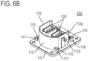
- FIGs. 6A , 6B , and 6C illustrating the mating connector 200 110 denotes a mating housing and 120 denotes a mating main terminal. Further, 130 denotes a mating interlock terminal.
- the mating connector 200 is to be mounted on a substrate.
- the mating housing 110 includes a plate portion 111 and an opposite fitting portion 112.
- the opposite fitting portion 112 is shaped like a frame opening upward and is located on the plate portion 111 in a protruding manner.
- the opposite fitting portion 112 has a circumferential wall 112a, which has a frame like shape.
- a pair of driven bosses 113 are formed on outer side surfaces of the left and right portions (in FIG. 6A ) of the circumferential wall 112a.
- the pair of driven bosses 113 protrude mutually outward.
- a rearward facing portion (in a direction correspondent to the front-rear direction of the housing 30) of the circumferential wall 112a is largely cut with a cutout 114.
- a pair of mating main terminals 120 is accommodated and positioned in the inside of the opposite fitting portion 112, and the mating interlock terminal 130 is accommodated and positioned in the inside of the opposite fitting portion 112 on the closer side to the cutout 114.
- a pair of mating flange portions 115 and a pair of mating flange portions 116 are further provided on the plate portion 111 of the mating housing 110. These four mating flange portions 115 and 116 are formed on respective upper ends of upright portions 117 and upright portions 118 that vertically rise from the plate portion 111.
- the mating flange portions 115, provided in a pair, are positioned on the left and right of the opposite fitting portion 112 (in FIG. 6A ) on the front side of the opposite fitting portion 112, and the mating flange portions 116, provided in a pair, are positioned on the left and right of the opposite fitting portion 112 on the rear side of the opposite fitting portion 112.
- the mating flange portions 115, provided in a pair, are configured to protrude mutually outward in the left-right direction, and the mating flange portions 116, provided in a pair, are also configured to protrude mutually outward in the left-right direction.
- FIGs. 9 , 10 , 11 , and 12 illustrate appearances in the states 1 and 3 to 5 respectively
- FIGs. 13A to 13C , FIGs. 14A to 14C , and FIGs. 15A to 15C illustrate details of principal portions in the states 1 to 3 respectively.
- FIGs. 16A to 16C , FIGs. 17A to 17C , and FIGs. 18A and 18B illustrate details of principal portions in the states 3 to 5 respectively.
- the state 1 is a state in which the fitting portion 31 of the housing 30 in the connector 100 whose lever 40 is on the first position is fitted to the opposite fitting portion 112 of the mating housing 110 in the mating connector 200 and the connector 100 is on a fitting preparation position with respect to the mating connector 200.
- the driven bosses 113, provided in a pair, of the mating connector 200 are inserted in respective cam grooves 44 of the lever 40 in the connector 100.
- the main terminals 50 and the mating main terminals 120 are not connected with each other yet and the interlock terminal 60 and the mating interlock terminal 130 are not connected with each other yet either.
- the state 2 is a state in which the lever 40 is rotated to an intermediate position between the first position and the second position.
- the connector 100 is drawn toward the mating connector 200 by a cam mechanism and moves to a main-terminal contact starting position between the fitting preparation position and a fitting position.
- the cam mechanism is composed of the cam grooves 44 of the lever 40 and the driven bosses 113, which enter the cam grooves 44, of the mating connector 200. Accordingly, the main terminals 50 and the mating main terminals 120 are connected with each other as illustrated in FIG. 14C , that is, the main terminals 50 and the mating main terminals 120 are connected with each other by the time when the lever 40 reaches the second position.
- the state 3 is a state in which the lever 40 is rotated to the second position that is a rotation completion position.
- the connector 100 is further drawn toward the mating connector 200 by the cam mechanism and moves to the fitting position which is closer to the mating connector 200.
- the connection between the main terminals 50 and the mating main terminals 120 is still maintained and the interlock terminal 60 and the mating interlock terminal 130 are connected with each other in this state 3 as illustrated in FIG. 15C . Consequently, the fitting is detected.
- FIG. 16C illustrates this state.
- the state 4 is a state in which the lever 40 is slid from the second position to the third position.
- the flange portions 36 and 37 of the housing 30 in the connector 100 and the mating flange portions 115 and 116 of the mating housing 110 in the mating connector 200 are accommodated in the groove portions 45 and 46, which are formed on the pair of arm portions 41 of the lever 40 in a manner to extend in a sliding direction (the longitudinal direction of the arm portions 41), in a manner to be in close contact with each other as illustrated in FIG. 17C .
- the flange portions 36 and 37 and the mating flange portions 115 and 116 are held by the lever 40 in a manner in which the flange portions 36 and the mating flange portions 115 are in close contact with each other and the flange portions 37 and the mating flange portions 116 are in close contact with each other.
- the state 5 is a state in which the locking component 70 is pushed in the arrow a direction.
- the end of the locking piece 71 of the locking component 70 is positioned beyond the locking portion 48 of the lever 40 as illustrated in FIG. 18B . Accordingly, the lever 40 is locked and cannot be slid. That is, CPA is achieved.
- the lock of the lever 40 can be released by pulling the locking component 70 in an opposite direction to the arrow a direction.
- the connector device is equipped with electronics outside of it that, when the main terminals 50 and the mating main terminals 120 for large current are connected with each other and the interlock terminal 60 and the mating interlock terminal 130 for HVILs are connected with each other to close an HVIL circuit, then allow large current to flow between the main terminals 50 and the mating main terminals 120.
- the lever 40 performs a rotation operation and a sliding operation.
- the rotation from the first position to the second position fits the connector 100 to the mating connector 200 and the subsequent sliding from the second position to the third position blocks the rotation of the lever 40, namely, locks the fitting.
- the flange portions 36 and the mating flange portions 115 are accommodated as being sandwiched in the groove portions 45 provided to the lever 40 in a manner in which the flange portions 36 and the mating flange portions 115 are in close contact with each other, and the flange portions 37 and the mating flange portions 116 are accommodated as being sandwiched in the groove portions 46 provided to the lever 40 in a manner in which the flange portions 37 and the mating flange portions 116 are in close contact with each other. Consequently, the housing 30 of the connector 100 and the mating housing 110 of the mating connector 200 are firmly held by the lever 40.
- a cross section orthogonal to the sliding direction of the lever 40 of each of the flange portions 36 and 37, mating flange portions 115 and 116, and groove portions 45 and 46 of the lever 40, in the state in which the connector 100 is positioned on the fitting position with respect to the mating connector 200 preferably has a thickness which increases toward a direction away from the housing 30 and the mating housing 110, that is, the protruding direction of the flange portions 36 and 37 and the mating flange portions 115 and 116.
- This configuration realizes securer holding of the flange portions 36 and 37 and the mating flange portions 115 and 116 by the groove portions 45 and 46 and can prevent cancellation of the holding caused by movement of the lever 40 in the lateral direction (the left-right direction (in FIG. 19A ) orthogonal to the sliding direction), for example.
- FIG. 19A illustrates the above-described cross-sectional shape of a portion in which the flange portion 36 and the mating flange portion 115 are held in the groove portion 45.
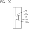
- the shape for securing the holding of the flange portions 36 and 37 and the mating flange portions 115 and 116 by the groove portions 45 and 46 is not limited to the cross-sectional shape illustrated in FIG. 19A but cross-sectional shapes as those illustrated in FIGs. 19B and 19C may further be employed.
- FIG. 19B illustrates a configuration in which projections 36a and 115a are formed on respective outer side surfaces of protruding-direction ends of the flange portion 36 and mating flange portion 115, and projections 45a are formed on respective inner side surfaces, which are opposed to each other, of an opening portion of the groove portion 45.
- FIG. 19C illustrates a configuration obtained by combining the groove portion 45 illustrated in FIG. 19A with the flange portion 36 and the mating flange portion 115 illustrated in FIG. 19B .
- the cross-sectional shapes of the projections 36a, 115a, and 45a are not limited to the shapes illustrated in FIGs. 19B and 19C but may be a square, a trapezoid, or a triangle.
- the lever 40 is provided with four groove portions 45 and 46, and the housing 30 of the connector 100 and the mating housing 110 of the mating connector 200 are held at four points around the fitting portion 31 of the housing 30.
- the number of groove portions that is, the numbers of flange portions and mating flange portions respectively provided to the housing 30 and the mating housing 110 are not limited to four.
- FIGs. 20A and 20B and FIGs. 21A to 21C respectively illustrate a connector 400 and a mating connector 500 that constitute a connector device according to a second embodiment.
- portions corresponding to those of the first embodiment will be provided with the same reference characters and detailed description thereof will be omitted.
- the lever 40 of the connector 400 rotates in a reverse direction to that of the first embodiment, that is, the lever 40 rotates in a direction away from the cables 300. Further, the interlock terminal 60 of the connector 400 is accommodated in an interlock housing 90 attached to the housing 30 in this example.
- the housing 30 of the connector 400 is composed of the fitting portion 31, the cable accommodating portion 32, and an attaching portion 39 that is positioned on the front surface of the fitting portion 31.
- the guide shafts 35 are formed in a pair on respective lateral surfaces of the fitting portion 31.
- the flange portions 36 are formed in a pair on the front sides of respective lateral surfaces of the fitting portion 31 and the flange portions 37 are formed in a pair on the rear sides of the respective lateral surfaces of the fitting portion 31.
- the attaching portion 39 is a portion to which the interlock housing 90 is attached and has a substantially cylindrical shape that is opened in the vertical direction.
- slits 39a are formed in a pair on mutually opposed positions. The slit 39a extends rearward from the front end of the attaching portion 39.
- the lever 40 includes the pair of arm portions 41, the coupling portion 42, and an operation portion 49, as illustrated in FIGs. 22A , 22B , 22C , 22D , and 22E .
- the coupling portion 42 couples proximal ends of the arm portions 41 provided in a pair.
- the operation portion 49 is positioned on a side opposite to the arm portions 41 with respect to the coupling portion 42 that is interposed therebetween.
- the operation portion 49 is positioned on the lower end side (in FIG. 22C ) of the coupling portion 42, and reinforcing walls 49a, which are provided in a pair and extend in the vertical direction (in FIG. 22C ), are positioned on both ends in the width direction of the operation portion 49 in a manner to be continuously formed between the coupling portion 42 and the operation portion 49.
- the guide groove 43 and the cam groove 44 are formed on each of the pair of arm portions 41. Further, the groove portions 46 are formed on the respective inner surfaces of the distal ends of the arm portions 41, and the groove portions 45 are further formed on the respective inner surfaces of their proximal portions.
- the groove portion 45 in this example is formed as a slit that opens on the outer surface of the arm portion 41.
- An opening 42a is formed on the lower portion of the coupling portion 42 and an opening 49b communicating with the opening 42a is also formed on the operation portion 49.
- wall portions 49c extending in the vertical direction (in FIG. 22C ) are respectively formed.
- slide insertion portions 49d are formed in a protruding manner.
- the slide insertion portion 49d is a projection that extends in the longitudinal direction of the arm portion 41 and has a cutout 49e on the middle in the longitudinal direction thereof.
- the interlock housing 90 includes a cylindrical portion 91 and an operation portion 92.
- the operation portion 92 is positioned on an upper end of the cylindrical portion 91 and has a shape to lid the cylindrical portion 91.
- the detailed configuration of the interlock housing 90 and its attachment to the attaching portion 39 of the housing 30 will be described later.
- the lever 40 is attached to the housing 30 similarly to the first embodiment and is to be positioned on the first position, the second position, or the third position with respect to the housing 30 as is the case with the first embodiment.
- FIGs. 20A and 20B illustrate a state in which the lever 40 is on the first position.
- the mating connector 500 is to be mounted on a substrate, and the mating housing 110 of the mating connector 500 includes the plate portion 111 and the opposite fitting portion 112 that is positioned on the plate portion 111, as illustrated in FIGs. 21A , 21B , and 21C .
- the pair of driven bosses 113 is formed on the circumferential wall 112a of the opposite fitting portion 112.
- the pair of mating flange portions 115 and the pair of mating flange portions 116 are formed in a manner to protrude from the circumferential wall 112a in this example.
- the pair of mating main terminals 120 is accommodated and positioned in the inside of the opposite fitting portion 112.
- an attaching portion 119 is formed on the plate portion 111 in a protruding manner.
- the attaching portion 119 has a cylindrical shape that opens upward and the mating interlock terminal 130 is attached and fixed to the attaching portion 119.
- FIG. 23 illustrates an appearance of the connector 400 and the mating connector 500 in a state before there fitting (immediately before the state A), and FIG. 24 illustrates an appearance of them in the state D in which the fitting is completed.
- FIGs. 25A and 25B and FIGs. 26A and 26B illustrate details of principal portions in the states B and C respectively, and FIGs. 27A and 27B and FIGs. 28A and 28B illustrate the interlock housing 90 in the states A to D.
- the state A is a state in which the fitting portion 31 of the housing 30 in the connector 400 whose lever 40 is on the first position is fitted to the fitted portion 112 of the mating housing 110 in the mating connector 500 and the connector 400 is on a fitting preparation position with respect to the mating connector 500.
- the driven bosses 113, provided in a pair, of the mating connector 500 are inserted in respective cam grooves 44 of the lever 40 in the connector 400.
- the main terminals 50 and the mating main terminals 120 are not connected with each other yet.
- protrusion portions 93a on ends (lower ends) of a pair of spring pieces 93 are positioned on natural positions in a manner to be in the respective slits 39a of the attaching portion 39 as illustrated in FIG. 27A .
- the spring piece 93 is formed by cutting the cylindrical portion 91, and the protrusion portion 93a protrudes outward.
- the interlock housing 90 cannot be pushed down even by pushing the operation portion 92 thereof because the protrusion portions 93a are abutted on abutting surfaces 39b, which are lower inner surfaces of the slits 39a, that is, the interlock housing 90 is blocked from sliding to a closing position, on which the interlock terminal 60 of the connector 400 and the mating interlock terminal 130 of the mating connector 500 are mutually connected.
- the state B is a state in which the lever 40 is rotated from the first position to the second position.
- the connector 400 is drawn to the fitting position with respect to the mating connector 500 by the cam mechanism, and the main terminals 50 of the connector 400 and the mating main terminals 120 of the mating connector 500 are connected with each other by the time when the lever 40 reaches the second position.
- the interlock housing 90 is on the opening position as in the state A. Even though the connector 400 is brought closer to the mating connector 500, the interlock terminal 60 and the mating interlock terminal 130 are not connected with each other yet and are still disconnected from each other, as illustrated in FIG. 27B .
- FIG. 25B illustrates this state.
- the state C is a state in which the lever 40 is slid from the second position to the third position and the slide insertion portions 49d, provided in a pair, of the lever 40 enter the slits 39a of the attaching portion 39 of the housing 30. Accordingly, the protrusion portions 93a of the pair of spring pieces 93 in the interlock housing 90 are pressed by respective pressing portions 49f (see FIGs. 22A , 22B , 22C , 22D , and 22E ) on the ends of the slide insertion portions 49d, being displaced from the natural positions to retracted positions, as illustrated in FIG. 28A .
- This enables the interlock housing 90, which is attached to the attaching portion 39 of the housing 30 in a manner to be able to slide between the opening position and the closing position for the interlock housing 90 to take, to slide to the closing position.
- the sliding of the lever 40 allows the flange portions 36 and 37 of the housing 30 in the connector 400 and the mating flange portions 115 and 116 of the mating housing 110 in the mating connector 500 to be accommodated in the groove portions 45 and 46 of the lever 40 in a manner in which the flange portions 36 and the mating flange portions 115 are in close contact with each other and the flange portions 37 and the mating flange portions 116 are in close contact with each other, whereby the flange portions 36 and 37 and the mating flange portions 115 and 116 are held by the lever 40, as illustrated in FIG. 26B .
- the state D is a state in which the interlock housing 90, which is positioned on the opening position in the state C, is pushed along with pushing of the operation portion 92 and slid to be positioned on the closing position.
- the interlock terminal 60 and the mating interlock terminal 130 are mutually connected as illustrated in FIG. 28B . Consequently, fitting is detected.
- the connector device of the second embodiment has been described above.
- the connector device of the second embodiment can provide the same advantageous effects as those of the connector device of the first embodiment described above.
- connection and disconnection of the HVILs are performed by pushing down and pulling up the interlock housing 90 that is provided separately from the lever 40. That is, the connection of the HVILs is performed in a manner such that after the main terminals 50 and the mating main terminals 120 are connected with each other through the rotation operation of the lever 40, the sliding operation of the lever 40 is performed and further, the interlock housing 90 is pushed down. On the other hand, the disconnection between the main terminals 50 and the mating main terminals 120 is performed in a manner such that after the HVILs are disconnected from each other by pulling up the interlock housing 90, the sliding operation of the lever 40 is performed and further, the rotation operation of the lever 40 is performed.
Landscapes
- Details Of Connecting Devices For Male And Female Coupling (AREA)
Description
- The present invention relates to a connector device in which fitting and separation between a connector and a mating connector are performed through a rotation operation and sliding operation of a lever.
-
FIG. 1 illustrates the configuration described inJapanese Patent Application Laid Open No. 2003-100382 connector housing 11 is mounted on theother connector housing 21 by operating alever 12 attached to the oneconnector housing 11. - A
terminal hood portion 11a is provided on the lower portion of theconnector housing 11, and a pair of terminals (male terminals) 13 is provided in theterminal hood portion 11a. On the outer wall of theconnector housing 11, a pair ofguide pins 11b is provided in a protruding manner. Theguide pins 11b are engaged withrespective guide grooves 14 of thelever 12 which will be described later. - As illustrated in
FIGs. 2A and2B , thelever 12 includes a pair ofarm plate portions operation portion 12c that couples thearm plate portions arm plate portions guide pins 11b, which are provided in a pair, of theconnector housing 11 are inserted into therespective guide grooves 14. Thus, thelever 12 is provided in a manner to be able to rotationally and linearly move with respect to theconnector housing 11. - On the
arm plate portions respective cam grooves 15 are formed in a pair. To thecam grooves 15,respective cam pins 21a, described later, of theother connector housing 21 are inserted when the oneconnector housing 11 is mounted on theother connector housing 21. - In this example, the
arm plate portion 12b is formed wider than thearm plate portion 12a. Thearm plate portion 12b having the wider width is provided with aconnector portion 12d and theconnector portion 12d is provided with a fitting detectionmale terminal 16. - The
other connector housing 21 has a substantially rectangular parallelepiped shape whose top surface is opened and whose inner space serves as amounting space 21b of theconnector housing 11. A terminalhood accommodating portion 21c is provided on a bottom surface portion, which is the bottom surface of themounting space 21b, and a pair of terminals (female terminals) 22 is accommodated in the terminalhood accommodating portion 21c. - The
respective cam pins 21a are provided in a pair in a protruding manner on symmetrical positions on an inner circumferential wall of theconnector housing 21, and aconnector portion 21d is further provided in themounting space 21b. Theconnector portion 21d is provided with a pair of fitting detection female terminals 23 (seeFIGs. 4A and4B described later). -
FIGs. 3A to 3C illustrate states of thelever 12 together with thecam pin 21a of theother connector housing 21 in a process of mounting the oneconnector housing 11 on theother connector housing 21 by inserting the oneconnector housing 11 into themounting space 21b of theother connector housing 21 from a state before the oneconnector housing 11 is mounted on theother connector housing 21, illustrated inFig. 1 .FIG. 3A illustrates a state in which thelever 12 is rotated from a rotation starting position illustrated inFIG. 1 to an arrow a direction to be positioned between the rotation starting position and a rotation completion position.FIG. 3B illustrates a state in which thelever 12 is on the rotation completion position. Further,FIG. 3C illustrates a state in which thelever 12 is slid to an arrow b direction and is on a fitting completion position. - The
cam pins 21a of theother connector housing 21 that are inserted into thecam grooves 15 of thelever 12 move along thecam grooves 15 along with the rotation of thelever 12. Accordingly, the oneconnector housing 11 gradually approaches and moves into theother connector housing 21 and this approach brings theterminals connector housings lever 12 comes to be positioned on the rotation completion position. - Then, when the
lever 12 is slidingly moved in the arrow b direction from the rotation completion position to the fitting completion position, the fitting detectionmale terminal 16 of thelever 12 comes into contact with the pair of fitting detectionfemale terminals 23 of the other connector housing 21 by the time when thelever 12 comes to be positioned on the fitting completion position.FIGs. 4A and4B illustrate a state in which thelever 12 is positioned on the fitting completion position and the mounting of the oneconnector housing 11 onto theother connector housing 21 is completed. - The operation of the
lever 12 is thus composed of two actions which are the rotation operation and the sliding operation. By the sliding operation after the rotation operation, the fitting detectionmale terminal 16 comes into contact with the fitting detectionfemale terminals 23 and the fitting is detected. This detection of the fitting allows a power source circuit to be in a conductive state and supply current between theterminals - The operation of the
lever 12 for shifting the power source circuit from the conductive state to a non-conductive state is composed of reverse two actions, where the power source circuit is turned off by the sliding operation performed first and theterminals 13 and theterminals 22 separate from each other through the rotation operation subsequently performed. - The connector device operating as described above can prevent a power source circuit from becoming into a conductive state before the operation of a lever thereof is completed and can prevent an occurrence of arc discharge. Thus, the connector device is designed in consideration of safety as a connector device for high voltage and large current.
- Such a connector device for high voltage and large current is used for, for example, connection between a battery and a cable harness in an electric vehicle and the like and is designed for securing safety of an operator in maintenance of an electrical system and the like.
- However, in-vehicle application of such a connector device may generate a problem in that components of a connector and a mating connector rub against each other when the connector and the mating connector relatively move due to vibration, which causes degradation in quality and connection performance.
- Prior art relating to or similar to those described as background art is known from, for example,
WO2014/041096A1 ,US2019/393649A1 , andUS10044138B2 -
WO2014/041096A1 , which discloses the preamble of claim 1, discloses a plug connector arrangement with a first and a second plug connector housing. The first plug connector housing is equipped with a rotary slide lever with two parallel, interconnected lateral surfaces which have multiple guide tracks. A first guide pin molded on the first plug connector housing is inserted into a first guide track of the rotary slide lever, whereby the rotary slide lever can be rotated and moved relative to the first plug connector housing when the plug connector housings are disconnected. The rotary slide lever has a second guide track into which a second guide pin molded on the second plug connector housing can be inserted in a first rotary position of the rotary slide lever, and the second guide pin can be moved in the second guide track by rotating the rotary slide lever, whereby the two plug connector housings are moved towards each other and contact elements arranged on the plug connector housings are connected to one another. In the rotary end position, the rotary slide lever can be moved perpendicularly to the connecting direction of the two plug connector housings, and the plug connector housings are pressed against each other at the end of the movement path, wherein an electric short-circuit bridge is arranged on a rotary slide lever portion which connects the two lateral surfaces, said short-circuit bridge connecting two electric contact elements on the second plug connector housing when the plug connector housings are connected to each other at the end of the movement path of the rotary slide lever. The short-circuit bridge is designed as part of a locking element which is movably arranged on the portion and which can be connected to the second plug connector housing in a formfitting manner at the end of the movement path of the rotary slide lever. -
US2019/393649A1 discloses an electrical connector that comprises a first housing, a second housing, a lever adapted to couple the first housing and the second housing with each other, a first interlock member, a second interlock member, a first cam mechanism adapted to mate the first housing and the second housing with each other with movement of the lever in a first direction, and a second cam mechanism. The second interlock member is configured to be mated with the first interlock member to energize an electric circuit. The first cam mechanism limits a moving direction of the lever to a second direction after moving in the first direction. The second cam mechanism is adapted to convert the movement of the lever in the second direction into movement in a mating direction of the first housing and the second housing to mate the first interlock member with the second interlock member. -
US10044138B2 - An object of the present invention is to provide a connector device whose quality and connection performance can be prevented from degrading even when the connector device is used in a vibration environment.
- The technical matters described herein are not intended to expressly or implicitly limit the invention described in the claims, or, moreover, are not a statement of the possibility of accepting such limitation imposed by persons other than those who benefit from the present invention (for example, the applicant and the right holder), but are merely described to facilitate an understanding of the gist of the present invention.
- A connector device according to the present invention includes a first connector and a second connector.
- The first connector includes a housing and a lever. The housing of the first connector includes a first lug (also referred to as a "flange portion" in this specification). The first lug has a flat surface.
- The lever of the first connector has a groove.
- The second connector includes a housing. The housing of the second connector includes a second lug (also referred to as a "mating flange portion" in this specification). The second lug has a flat surface.
- The first connector is fitted to the second connector through a rotation operation of the lever from a first position to a second position. In this fitted state, the flat surface of the first lug and the flat surface of the second lug are in close contact with each other.
- Through a sliding operation of the lever from the second position to a third position, the first lug and the second lug are housed in the groove of the lever in a manner in which the first lug and the second lug are in close contact with each other. Backlash between the set of first and second lugs, being in close contact with each other, and the groove of the lever is preferably as small as possible in a direction in which the first connector is fitted to the second connector.
- This configuration can prevent relative movement between the first connector and the second connector, especially relative movement between the first connector and the second connector in a direction in which the first connector is fitted to the second connector.
- Preferably, the connector device may include, but not limited to, a locking mechanism for blocking the sliding operation of the lever. The set of first and second lugs which are in close contact with each other is securely held in the groove of the lever because the locking mechanism blocks the sliding operation of the lever.
- Preferably, the configuration, but not limited to such configuration, is also permitted that the lever has a pair of arms, where one arm has two different groove portions on respective portions in a longitudinal direction of the one arm, the other arm has two different groove portions on respective portions in a longitudinal direction of the other arm, and these four groove portions house respective four sets of the first and second lugs that are each in close contact with each other. This configuration can stably and robustly prevent relative movement between the first connector and the second connector.
- The "housing" is not limited to an object that is narrowly interpreted according to its dictionary definition. That is, "housing" is not limited to an object that has only a function based on the dictionary definition of the term (however, this object may be a single element or may be composed of two or more elements), or is not limited to a portion of a single object that has a function based on the dictionary definition of the term. A "housing" may be an object that has only a function based on the dictionary definition of the term, or it may be an object that has a function not based on the dictionary definition of the term, or it may be an object that has other functions in addition to the function based on the dictionary definition of the term, or it may be a single object that includes portions having the function based on the dictionary definition of the term and portions not having the function based on the dictionary definition of the term.
- According to the connector device of the present invention, relative movement (rattling) between a housing of a connector and a mating housing of a mating connector can be prevented. Thus, a connector device whose quality and connection performance do not degrade even when used in a vibration environment and that exhibits superior vibration resistance can be obtained.
-
-
FIG. 1 is a perspective view illustrating a conventional example of a connector device. -
FIG. 2A is a perspective view of a lever ofFIG. 1 . -
FIG. 2B is a lateral view of the lever ofFIG. 1 . -
FIG. 3A is an elevational view illustrating a state in which the lever is positioned between a rotation starting position and a rotation completion position. -
FIG. 3B is an elevational view illustrating a state in which the lever is positioned on the rotation completion position. -
FIG. 3C is an elevational view illustrating a state in which the lever is positioned on a fitting completion position. -
FIG. 4A is a partial sectional view illustrating a mounting completion state of the connector device illustrated inFIG. 1 . -
FIG. 4B is an enlarged view illustrating principal portions ofFIG. 4A . -
FIG. 5A is an upper perspective view illustrating a connector of a connector device according to a first embodiment of the present invention. -
FIG. 5B is a lower perspective view of the connector illustrated inFIG. 5A . -
FIG. 6A is an elevational view illustrating a mating connector of the connector device according to the first embodiment of the present invention. -
FIG. 6B is a front side perspective view of the mating connector illustrated inFIG. 6A . -
FIG. 6C is a rear side perspective view of the mating connector illustrated inFIG. 6A . -
FIG. 7A is an elevational view of a housing ofFIG. 5A . -
FIG. 7B is a right side view of the housing ofFIG. 5A . -
FIG. 7C is a perspective view of the housing ofFIG. 5A viewed from above the housing. -
FIG. 7D is a perspective view of the housing ofFIG. 5A viewed from below the housing. -
FIG. 8A is a plan view of a lever ofFIG. 5A . -
FIG. 8B is an elevational view of the lever ofFIG. 5A . -
FIG. 8C is a perspective view of the lever ofFIG. 5A viewed from an upper front side. -
FIG. 8D is a perspective view of the lever ofFIG. 5A viewed from a lower front side. -
FIG. 8E is a perspective view of the lever ofFIG. 5A viewed from an upper rear side. -
FIG. 8F is a perspective view of the lever ofFIG. 5A viewed from a lower rear side. -
FIG. 9 is a perspective view illustrating a state in which the connector of the connector device according to the first embodiment of the present invention is on a fitting preparation position. -
FIG. 10 is a perspective view illustrating a state in which the lever is rotated to a second position from the state illustrated inFIG. 9 . -
FIG. 11 is a perspective view illustrating a state in which the lever is slid to a third position from the state illustrated inFIG. 10 . -
FIG. 12 is a perspective view illustrating a state in which a locking component is pushed from the state illustrated inFIG. 11 . -
FIG. 13A is a plan view of the state illustrated inFIG. 9 . -
FIG. 13B is a right side view ofFIG. 13A . -
FIG. 13C is an enlarged view of a section taken along the D-D line ofFIG. 13A . -
FIG. 14A is a plan view illustrating a state in which the lever is rotated to an intermediate position between a first position and the second position from the state illustrated inFIG. 9 . -
FIG. 14B is a right side view ofFIG. 14A . -
FIG. 14C is an enlarged view of a section taken along the D-D line ofFIG. 14A . -
FIG. 15A is a plan view of the state illustrated inFIG. 10 . -
FIG. 15B is a right side view ofFIG. 15A . -
FIG. 15C is an enlarged view of a section taken along the D-D line ofFIG. 15A . -
FIG. 16A is a plan view of the state illustrated inFIG. 10 . -
FIG. 16B is a sectional view taken along the D-D line ofFIG. 16A . -
FIG. 16C is a sectional view taken along the E-E line ofFIG. 16A . -
FIG. 17A is a plan view of the state illustrated inFIG. 11 . -
FIG. 17B is a sectional view taken along the D-D line ofFIG. 17A . -
FIG. 17C is a sectional view taken along the E-E line ofFIG. 17A . -
FIG. 18A is a plan view of the state illustrated inFIG. 12 . -
FIG. 18B is a sectional view taken along the C-C line ofFIG. 18A . -
FIG. 19A illustrates a first shape example of a flange portion, a mating flange portion, and a groove portion. -
FIG. 19B illustrates a second shape example of the flange portion, the mating flange portion, and the groove portion. -
FIG. 19C illustrates a third shape example of the flange portion, the mating flange portion, and the groove portion. -
FIG. 20A is an upper perspective view illustrating a connector of a connector device according to a second embodiment of the present invention. -
FIG. 20B is a lower perspective view of the connector illustrated inFIG. 20A . -
FIG. 21A is an elevational view illustrating a mating connector of the connector device according to the second embodiment of the present invention. -
FIG. 21B is a front side perspective view of the mating connector illustrated inFIG. 21A . -
FIG. 21C is a rear side perspective view of the mating connector illustrated inFIG. 21A . -
FIG. 22A is a lateral view of a lever ofFIG. 20A . -
FIG. 22B is a rear view of the lever ofFIG. 20A . -
FIG. 22C is a perspective view of the lever ofFIG. 20A viewed from an upper front side. -
FIG. 22D is a perspective view of the lever ofFIG. 20A viewed from a lower rear side. -
FIG. 22E is a sectional view taken along the F-F line ofFIG. 22A . -
FIG. 23 is a perspective view illustrating a state before fitting the connector illustrated inFIG. 20A to the mating connector illustrated inFIG. 21A . -
FIG. 24 is a perspective view illustrating a connection completion state between the connector illustrated inFIG. 20A and the mating connector illustrated inFIG. 21A . -
FIG. 25A is a plan view illustrating a state in which the connector illustrated inFIG. 20A and the mating connector illustrated inFIG. 21A are fitted to each other and the lever is rotated to a second position. -
FIG. 25B is a sectional view taken along the C-C line ofFIG. 25A . -
FIG. 26A is a plan view illustrating a state in which the lever is slid to a third position from the state illustrated inFIG. 25A . -
FIG. 26B is a sectional view taken along the C-C line ofFIG. 26A . -
FIG. 27A is a partially enlarged sectional view illustrating a state of an interlock housing in a state in which the connector of the connector device according to the second embodiment of the present invention is on a fitting preparation position. -
FIG. 27B is a partially enlarged sectional view illustrating a state in which the lever is rotated to the second position from the state illustrated inFIG. 27A . -
FIG. 28A is a partially enlarged sectional view illustrating a state in which the lever is slid to the third position from the state illustrated inFIG. 27B . -
FIG. 28B is a partially enlarged sectional view illustrating a state in which the interlock housing is slid to a closing position from the state illustrated inFIG. 28A . -
- 11: connector housing
- 11a: terminal hood portion
- 11b: guide pin
- 12: lever
- 12a: arm plate portion
- 12b: arm plate portion
- 12c: operation portion
- 12d: connector portion
- 13: terminal
- 14: guide groove
- 15: cam groove
- 16: fitting detection male terminal
- 21: connector housing
- 21a: cam pin
- 21b: mounting space
- 21c: terminal hood accommodating portion
- 21d: connector portion
- 22: terminal
- 23: fitting detection female terminal
- 30: housing
- 31: fitting portion
- 32: cable accommodating portion
- 33: accommodating portion
- 34: accommodating portion
- 35: guide shaft
- 36: flange portion
- 37: flange portion
- 36a: projection
- 38: groove
- 38a: protrusion
- 39: attaching portion
- 39a: slit
- 39b: abutting surface
- 40: lever
- 41: arm portion
- 42: coupling portion
- 42a: opening
- 43: guide groove
- 44: cam groove
- 45: groove portion
- 46: groove portion
- 45a: projection
- 47: attaching portion
- 48: locking portion
- 49: operation portion
- 49a: reinforcing wall
- 49b: opening
- 49c: wall portion
- 49d: slide insertion portion
- 49e: cutout
- 49f: pressing portion
- 50: main terminal
- 60: interlock terminal
- 70: locking component
- 71: locking piece
- 80: cable cover
- 90: interlock housing
- 91: cylindrical portion
- 92: operation portion
- 93: spring piece
- 93a: protrusion portion
- 100: connector
- 110: mating housing
- 111: plate portion
- 112: opposite fitting portion
- 112a: circumferential wall
- 113: driven boss
- 114: cutout
- 115: mating flange portion
- 116: mating flange portion
- 115a: projection
- 117: upright portion
- 118: upright portion
- 119: attaching portion
- 120: mating main terminal
- 130: mating interlock terminal
- 200: mating connector
- 300: cable
- 400: connector
- 500: mating connector
- Embodiments of the present invention will be described based on examples with reference to the accompanying drawings.
-
FIGs. 5A and5B andFIGs. 6A to 6C respectively illustrate aconnector 100 and amating connector 200 that constitute a connector device according to a first embodiment of the present invention, and the connector device composed of theconnector 100 and themating connector 200 is a connector device for high voltage and large current, including high-voltage interlocks (HVILs) and being used in-vehicle. - In
FIGs. 5A and5B , 30 denotes a housing and 40 denotes a lever. 300 denotes a cable, and theconnector 100 is attached to terminals of twocables 300 in this example. In thehousing 30,main terminals 50 that are respectively connected with the twocables 300 are accommodated and aninterlock terminal 60 is further accommodated. Further, alocking component 70 for connector position assurance (CPA) is attached to thelever 40. InFIG. 5A , 80 denotes a cable cover that is attached to thehousing 30. - The configurations of the
housing 30 and thelever 40 of theconnector 100 will be first described. - The
housing 30 is roughly composed of afitting portion 31 and acable accommodating portion 32 that adjoins the rear portion of thefitting portion 31, as illustrated inFIGs. 7A ,7B ,7C , and7D . Thefitting portion 31 has twoaccommodating portions 33 that are largely opened on bottom surfaces thereof, and themain terminals 50 are to be accommodated and disposed in respectiveaccommodating portions 33. Anotheraccommodating portion 34 that is opened on the bottom surface thereof is further provided in addition to theaccommodating portions 33 and theinterlock terminal 60 is to be accommodated and disposed in theaccommodating portion 34. -
Guide shafts 35 are formed in a pair substantially on the centers of both lateral surfaces in the front-rear direction of thefitting portion 31 in a manner to protrude mutually outward. Further,flange portions 36 are formed in a pair on front sides (opposite side to a side on which thecable accommodating portion 32 is positioned) of both lateral surfaces of thefitting portion 31 in a manner to protrude mutually outward. Furthermore, on both lateral surfaces of thehousing 30,flange portions 37 are formed in a pair connecting both to thefitting portion 31 and to thecable accommodating portion 32 in a manner to protrude mutually outward. These fourflange portions housing 30. - A
groove 38 is formed on the upper surface of thehousing 30. Thegroove 38 is extended from a rear end of thecable accommodating portion 32 to thefitting portion 31 in the front-rear direction. Aprotrusion 38a is formed in thegroove 38 in a protruding manner on a front end portion of thegroove 38. - As illustrated in
FIGs. 8A ,8B ,8C ,8D ,8E , and8F , thelever 40 is composed of a pair ofarm portions 41 that have a plate shape and acoupling portion 42 that couples upper ends (inFIGs. 8C ,8D ,8E , and8F ) of the proximal sides of the pair ofarm portions 41. On therespective arm portions 41, guidegrooves 43 are formed andcam grooves 44 are further formed. Theguide grooves 43 extend in the longitudinal direction of thearm portions 41. Thecam groove 44 has a curved shape and the distal end of thecam groove 44 is positioned on the distal end of thearm portion 41, as illustrated inFIGs. 8A ,8B ,8C ,8D ,8E , and8F . -
Groove portions 45 are formed on respective inner surfaces of the distal ends of thearm portions 41, andgroove portions 46 are further formed on the respective inner surfaces of their proximal portions. These fourgroove portions arm portion 41. On the other hand, an attachingportion 47 for attaching thelocking component 70 is formed on an upper surface (inFIGs. 8C and8E ) of thecoupling portion 42 at the center of its longitudinal direction. - The
locking component 70 is attached to thelever 40 having the above-described configuration. Thelever 40, to which thelocking component 70 is attached, is attached to thehousing 30 in a manner such that theguide shafts 35, provided in a pair, of thehousing 30 are inserted in and positioned onrespective guide grooves 43 of the pair ofarm portions 41 and thearm portions 41 sandwich thehousing 30. Thelever 40 can, in reference to thehousing 30, rotate between a first position and a second position for thelever 40 to take and can slide between the second position and a third position for it also to take, as described later.FIGs. 5A and5B illustrate a state in which thelever 40 is on the first position. - On the other hand, in
FIGs. 6A ,6B , and6C illustrating themating connector mating connector 200 is to be mounted on a substrate. - The
mating housing 110 includes aplate portion 111 and an oppositefitting portion 112. The oppositefitting portion 112 is shaped like a frame opening upward and is located on theplate portion 111 in a protruding manner. The oppositefitting portion 112 has acircumferential wall 112a, which has a frame like shape. A pair of drivenbosses 113 are formed on outer side surfaces of the left and right portions (inFIG. 6A ) of thecircumferential wall 112a. The pair of drivenbosses 113 protrude mutually outward. Further, a rearward facing portion (in a direction correspondent to the front-rear direction of the housing 30) of thecircumferential wall 112a is largely cut with acutout 114. A pair of matingmain terminals 120 is accommodated and positioned in the inside of the oppositefitting portion 112, and themating interlock terminal 130 is accommodated and positioned in the inside of the oppositefitting portion 112 on the closer side to thecutout 114. - On the
plate portion 111 of themating housing 110, a pair ofmating flange portions 115 and a pair ofmating flange portions 116 are further provided. These fourmating flange portions upright portions 117 andupright portions 118 that vertically rise from theplate portion 111. Themating flange portions 115, provided in a pair, are positioned on the left and right of the opposite fitting portion 112 (inFIG. 6A ) on the front side of the oppositefitting portion 112, and themating flange portions 116, provided in a pair, are positioned on the left and right of the oppositefitting portion 112 on the rear side of the oppositefitting portion 112. Themating flange portions 115, provided in a pair, are configured to protrude mutually outward in the left-right direction, and themating flange portions 116, provided in a pair, are also configured to protrude mutually outward in the left-right direction. - A fitting operation between the
connector 100 and themating connector 200 which are described above will now be described. - The fitting between the
connector 100 and themating connector 200 is completed through a fitting process including states 1 to 5.FIGs. 9 ,10 ,11 , and12 illustrate appearances in the states 1 and 3 to 5 respectively, andFIGs. 13A to 13C ,FIGs. 14A to 14C , andFIGs. 15A to 15C illustrate details of principal portions in the states 1 to 3 respectively. Further,FIGs. 16A to 16C ,FIGs. 17A to 17C , andFIGs. 18A and18B illustrate details of principal portions in the states 3 to 5 respectively. - The state 1 is a state in which the
fitting portion 31 of thehousing 30 in theconnector 100 whoselever 40 is on the first position is fitted to the oppositefitting portion 112 of themating housing 110 in themating connector 200 and theconnector 100 is on a fitting preparation position with respect to themating connector 200. The drivenbosses 113, provided in a pair, of themating connector 200 are inserted inrespective cam grooves 44 of thelever 40 in theconnector 100. In the state 1, themain terminals 50 and the matingmain terminals 120 are not connected with each other yet and theinterlock terminal 60 and themating interlock terminal 130 are not connected with each other yet either. - The state 2 is a state in which the
lever 40 is rotated to an intermediate position between the first position and the second position. In the state 2, theconnector 100 is drawn toward themating connector 200 by a cam mechanism and moves to a main-terminal contact starting position between the fitting preparation position and a fitting position. The cam mechanism is composed of thecam grooves 44 of thelever 40 and the drivenbosses 113, which enter thecam grooves 44, of themating connector 200. Accordingly, themain terminals 50 and the matingmain terminals 120 are connected with each other as illustrated inFIG. 14C , that is, themain terminals 50 and the matingmain terminals 120 are connected with each other by the time when thelever 40 reaches the second position. - When the
connector 100 whoselever 40 is on the intermediate position is on the main-terminal contact starting position of the state 2 with respect to themating connector 200, a rotation of thelever 40 to the first position causes theconnector 100 to be pushed back by the cam mechanism apart from the main-terminal contact starting position and to move to the fitting preparation position. When theconnector 100 leaves the main-terminal contact starting position, the connection between themain terminals 50 and the matingmain terminals 120 is released. - The state 3 is a state in which the
lever 40 is rotated to the second position that is a rotation completion position. In the state 3, theconnector 100 is further drawn toward themating connector 200 by the cam mechanism and moves to the fitting position which is closer to themating connector 200. The connection between themain terminals 50 and the matingmain terminals 120 is still maintained and theinterlock terminal 60 and themating interlock terminal 130 are connected with each other in this state 3 as illustrated inFIG. 15C . Consequently, the fitting is detected. - When the
connector 100 whoselever 40 is on the second position is on the fitting position of the state 3 with respect to themating connector 200, a rotation of thelever 40 to the intermediate position causes theconnector 100 to leave the fitting position and to move to the main-terminal contact starting position. When theconnector 100 leaves the fitting position, the connection between theinterlock terminal 60 and themating interlock terminal 130 is released in a state in which the connection between themain terminals 50 and the matingmain terminals 120 is maintained. - An end of a
locking piece 71 provided to thelocking component 70, which is provided to thelever 40 for CPA, is abutted on a lockingportion 48, provided to thelever 40, in the state 3 as illustrated inFIGs. 15C and16B . Thus, the lockingcomponent 70 cannot be pushed in the arrow a direction. - The four
flange portions housing 30 of theconnector 100 and the four correspondingmating flange portions mating housing 110 of themating connector 200 are in close contact with each other in this state 3.FIG. 16C illustrates this state. - The state 4 is a state in which the
lever 40 is slid from the second position to the third position. In the state 4, theflange portions housing 30 in theconnector 100 and themating flange portions mating housing 110 in themating connector 200 are accommodated in thegroove portions arm portions 41 of thelever 40 in a manner to extend in a sliding direction (the longitudinal direction of the arm portions 41), in a manner to be in close contact with each other as illustrated inFIG. 17C . That is, theflange portions mating flange portions lever 40 in a manner in which theflange portions 36 and themating flange portions 115 are in close contact with each other and theflange portions 37 and themating flange portions 116 are in close contact with each other. - When the
lever 40 of theconnector 100 which is on the fitting position with respect to themating connector 200 is slid from the third position to the second position, the holding of theflange portions mating flange portions lever 40 is released. - Meanwhile, when the
lever 40 is slid from the second position to the third position, the end of the lockingpiece 71 of thelocking component 70 rides on theprotrusion 38a, provided to thehousing 30, as illustrated inFIG. 17B . Thus, the abutment on the lockingportion 48 is released, allowing thelocking component 70 to be pushed in the arrow a direction. - The state 5 is a state in which the
locking component 70 is pushed in the arrow a direction. In the state 5, the end of the lockingpiece 71 of thelocking component 70 is positioned beyond the lockingportion 48 of thelever 40 as illustrated inFIG. 18B . Accordingly, thelever 40 is locked and cannot be slid. That is, CPA is achieved. - The lock of the
lever 40 can be released by pulling thelocking component 70 in an opposite direction to the arrow a direction. - The configuration and the fitting operation of the connector device according to the first embodiment of the present invention that is composed of the
connector 100 and themating connector 200 have been described above. The connector device is equipped with electronics outside of it that, when themain terminals 50 and the matingmain terminals 120 for large current are connected with each other and theinterlock terminal 60 and themating interlock terminal 130 for HVILs are connected with each other to close an HVIL circuit, then allow large current to flow between themain terminals 50 and the matingmain terminals 120. - According to the connector device of the first embodiment described above, the following advantageous effects can be obtained.
- The
lever 40 performs a rotation operation and a sliding operation. The rotation from the first position to the second position fits theconnector 100 to themating connector 200 and the subsequent sliding from the second position to the third position blocks the rotation of thelever 40, namely, locks the fitting. In this example, in the sliding of thelever 40 from the second position to the third position, theflange portions 36 and themating flange portions 115 are accommodated as being sandwiched in thegroove portions 45 provided to thelever 40 in a manner in which theflange portions 36 and themating flange portions 115 are in close contact with each other, and theflange portions 37 and themating flange portions 116 are accommodated as being sandwiched in thegroove portions 46 provided to thelever 40 in a manner in which theflange portions 37 and themating flange portions 116 are in close contact with each other. Consequently, thehousing 30 of theconnector 100 and themating housing 110 of themating connector 200 are firmly held by thelever 40. - Accordingly, relative movement (rattling) between the
connector 100 and themating connector 200 can be prevented, being able to prevent an occurrence of failures such as rubbing and scraping between housings, rubbing and scraping between terminals, and peeling of plating due to rattling. Thus, superior vibration resistance can be obtained. That is, a connector device can be realized whose quality and connection performance do not degrade even when used in a vibration environment. - Here, a cross section orthogonal to the sliding direction of the
lever 40 of each of theflange portions mating flange portions groove portions lever 40, in the state in which theconnector 100 is positioned on the fitting position with respect to themating connector 200, preferably has a thickness which increases toward a direction away from thehousing 30 and themating housing 110, that is, the protruding direction of theflange portions mating flange portions flange portions mating flange portions groove portions lever 40 in the lateral direction (the left-right direction (inFIG. 19A ) orthogonal to the sliding direction), for example. -
FIG. 19A illustrates the above-described cross-sectional shape of a portion in which theflange portion 36 and themating flange portion 115 are held in thegroove portion 45. - The shape for securing the holding of the
flange portions mating flange portions groove portions FIG. 19A but cross-sectional shapes as those illustrated inFIGs. 19B and19C may further be employed. -
FIG. 19B illustrates a configuration in whichprojections flange portion 36 andmating flange portion 115, andprojections 45a are formed on respective inner side surfaces, which are opposed to each other, of an opening portion of thegroove portion 45. Further,FIG. 19C illustrates a configuration obtained by combining thegroove portion 45 illustrated inFIG. 19A with theflange portion 36 and themating flange portion 115 illustrated inFIG. 19B . The cross-sectional shapes of theprojections FIGs. 19B and19C but may be a square, a trapezoid, or a triangle. - In this example, the
lever 40 is provided with fourgroove portions housing 30 of theconnector 100 and themating housing 110 of themating connector 200 are held at four points around thefitting portion 31 of thehousing 30. However, the number of groove portions, that is, the numbers of flange portions and mating flange portions respectively provided to thehousing 30 and themating housing 110 are not limited to four. -
FIGs. 20A and20B andFIGs. 21A to 21C respectively illustrate aconnector 400 and amating connector 500 that constitute a connector device according to a second embodiment. In respective components of theconnector 400 and themating connector 500, portions corresponding to those of the first embodiment will be provided with the same reference characters and detailed description thereof will be omitted. - In this example, the
lever 40 of theconnector 400 rotates in a reverse direction to that of the first embodiment, that is, thelever 40 rotates in a direction away from thecables 300. Further, theinterlock terminal 60 of theconnector 400 is accommodated in aninterlock housing 90 attached to thehousing 30 in this example. - The
housing 30 of theconnector 400 is composed of thefitting portion 31, thecable accommodating portion 32, and an attachingportion 39 that is positioned on the front surface of thefitting portion 31. Theguide shafts 35 are formed in a pair on respective lateral surfaces of thefitting portion 31. Further, theflange portions 36 are formed in a pair on the front sides of respective lateral surfaces of thefitting portion 31 and theflange portions 37 are formed in a pair on the rear sides of the respective lateral surfaces of thefitting portion 31. The attachingportion 39 is a portion to which theinterlock housing 90 is attached and has a substantially cylindrical shape that is opened in the vertical direction. On an intermediate portion of the attachingportion 39 in the vertical direction, slits 39a are formed in a pair on mutually opposed positions. Theslit 39a extends rearward from the front end of the attachingportion 39. - The
lever 40 includes the pair ofarm portions 41, thecoupling portion 42, and anoperation portion 49, as illustrated inFIGs. 22A ,22B ,22C ,22D , and22E . Thecoupling portion 42 couples proximal ends of thearm portions 41 provided in a pair. Theoperation portion 49 is positioned on a side opposite to thearm portions 41 with respect to thecoupling portion 42 that is interposed therebetween. Theoperation portion 49 is positioned on the lower end side (inFIG. 22C ) of thecoupling portion 42, and reinforcingwalls 49a, which are provided in a pair and extend in the vertical direction (inFIG. 22C ), are positioned on both ends in the width direction of theoperation portion 49 in a manner to be continuously formed between thecoupling portion 42 and theoperation portion 49. - On each of the pair of
arm portions 41, theguide groove 43 and thecam groove 44 are formed. Further, thegroove portions 46 are formed on the respective inner surfaces of the distal ends of thearm portions 41, and thegroove portions 45 are further formed on the respective inner surfaces of their proximal portions. Here, thegroove portion 45 in this example is formed as a slit that opens on the outer surface of thearm portion 41. - An
opening 42a is formed on the lower portion of thecoupling portion 42 and anopening 49b communicating with theopening 42a is also formed on theoperation portion 49. On both sides in the width direction of theopening 49b of theoperation portion 49,wall portions 49c extending in the vertical direction (inFIG. 22C ) are respectively formed. On respective inner side surfaces of thewall portions 49c,slide insertion portions 49d are formed in a protruding manner. Theslide insertion portion 49d is a projection that extends in the longitudinal direction of thearm portion 41 and has acutout 49e on the middle in the longitudinal direction thereof. - The
interlock housing 90 includes acylindrical portion 91 and anoperation portion 92. Theoperation portion 92 is positioned on an upper end of thecylindrical portion 91 and has a shape to lid thecylindrical portion 91. The detailed configuration of theinterlock housing 90 and its attachment to the attachingportion 39 of thehousing 30 will be described later. - The
lever 40 is attached to thehousing 30 similarly to the first embodiment and is to be positioned on the first position, the second position, or the third position with respect to thehousing 30 as is the case with the first embodiment.FIGs. 20A and20B illustrate a state in which thelever 40 is on the first position. - The
mating connector 500 is to be mounted on a substrate, and themating housing 110 of themating connector 500 includes theplate portion 111 and the oppositefitting portion 112 that is positioned on theplate portion 111, as illustrated inFIGs. 21A ,21B , and21C . On thecircumferential wall 112a of the oppositefitting portion 112, the pair of drivenbosses 113 is formed. The pair ofmating flange portions 115 and the pair ofmating flange portions 116 are formed in a manner to protrude from thecircumferential wall 112a in this example. The pair of matingmain terminals 120 is accommodated and positioned in the inside of the oppositefitting portion 112. - At the front of the opposite
fitting portion 112, that is, at an opposite side to a side on which thecutout 114 formed on thecircumferential wall 112a is positioned, an attachingportion 119 is formed on theplate portion 111 in a protruding manner. The attachingportion 119 has a cylindrical shape that opens upward and themating interlock terminal 130 is attached and fixed to the attachingportion 119. - A fitting operation between the
connector 400 and themating connector 500 which are described above will now be described. - The fitting process between the
connector 400 and themating connector 500 can be described based on four states that are states A to D.FIG. 23 illustrates an appearance of theconnector 400 and themating connector 500 in a state before there fitting (immediately before the state A), andFIG. 24 illustrates an appearance of them in the state D in which the fitting is completed. Further,FIGs. 25A and25B andFIGs. 26A and26B illustrate details of principal portions in the states B and C respectively, andFIGs. 27A and27B andFIGs. 28A and28B illustrate theinterlock housing 90 in the states A to D. - The state A is a state in which the
fitting portion 31 of thehousing 30 in theconnector 400 whoselever 40 is on the first position is fitted to the fittedportion 112 of themating housing 110 in themating connector 500 and theconnector 400 is on a fitting preparation position with respect to themating connector 500. The drivenbosses 113, provided in a pair, of themating connector 500 are inserted inrespective cam grooves 44 of thelever 40 in theconnector 400. In the state A, themain terminals 50 and the matingmain terminals 120 are not connected with each other yet. - In the
interlock housing 90 that is attached to the attachingportion 39 of thehousing 30 in theconnector 400 in a manner to be able to slide between an opening position and a closing position,protrusion portions 93a on ends (lower ends) of a pair ofspring pieces 93 are positioned on natural positions in a manner to be in therespective slits 39a of the attachingportion 39 as illustrated inFIG. 27A . Thespring piece 93 is formed by cutting thecylindrical portion 91, and theprotrusion portion 93a protrudes outward. Accordingly, theinterlock housing 90 cannot be pushed down even by pushing theoperation portion 92 thereof because theprotrusion portions 93a are abutted on abuttingsurfaces 39b, which are lower inner surfaces of theslits 39a, that is, theinterlock housing 90 is blocked from sliding to a closing position, on which theinterlock terminal 60 of theconnector 400 and themating interlock terminal 130 of themating connector 500 are mutually connected. - The state B is a state in which the
lever 40 is rotated from the first position to the second position. In the state B, theconnector 400 is drawn to the fitting position with respect to themating connector 500 by the cam mechanism, and themain terminals 50 of theconnector 400 and the matingmain terminals 120 of themating connector 500 are connected with each other by the time when thelever 40 reaches the second position. - The
interlock housing 90 is on the opening position as in the state A. Even though theconnector 400 is brought closer to themating connector 500, theinterlock terminal 60 and themating interlock terminal 130 are not connected with each other yet and are still disconnected from each other, as illustrated inFIG. 27B . - The four
flange portions housing 30 of theconnector 400 and the four correspondingmating flange portions mating housing 110 of themating connector 500 are in close contact with each other in this state.FIG. 25B illustrates this state. - The state C is a state in which the
lever 40 is slid from the second position to the third position and theslide insertion portions 49d, provided in a pair, of thelever 40 enter theslits 39a of the attachingportion 39 of thehousing 30. Accordingly, theprotrusion portions 93a of the pair ofspring pieces 93 in theinterlock housing 90 are pressed by respectivepressing portions 49f (seeFIGs. 22A ,22B ,22C ,22D , and22E ) on the ends of theslide insertion portions 49d, being displaced from the natural positions to retracted positions, as illustrated inFIG. 28A . This enables theinterlock housing 90, which is attached to the attachingportion 39 of thehousing 30 in a manner to be able to slide between the opening position and the closing position for theinterlock housing 90 to take, to slide to the closing position. - The sliding of the
lever 40 allows theflange portions housing 30 in theconnector 400 and themating flange portions mating housing 110 in themating connector 500 to be accommodated in thegroove portions lever 40 in a manner in which theflange portions 36 and themating flange portions 115 are in close contact with each other and theflange portions 37 and themating flange portions 116 are in close contact with each other, whereby theflange portions mating flange portions lever 40, as illustrated inFIG. 26B . - The state D is a state in which the
interlock housing 90, which is positioned on the opening position in the state C, is pushed along with pushing of theoperation portion 92 and slid to be positioned on the closing position. In the state D, theinterlock terminal 60 and themating interlock terminal 130 are mutually connected as illustrated inFIG. 28B . Consequently, fitting is detected. - In the state in which the
interlock housing 90 is pushed down to the closing position, although detailed illustrations are omitted, a pair of lever slide blocking portions, which is formed on thecylindrical portion 91 of theinterlock housing 90 in a manner to protrude outward, enter thecutouts 49e which are formed on theslide insertion portions 49d of thelever 40. Accordingly, thelever 40 is fixed on the third position and sliding back to the second position is blocked. - The connector device of the second embodiment has been described above. The connector device of the second embodiment can provide the same advantageous effects as those of the connector device of the first embodiment described above.
- In addition, in the second embodiment, the connection and disconnection of the HVILs are performed by pushing down and pulling up the
interlock housing 90 that is provided separately from thelever 40. That is, the connection of the HVILs is performed in a manner such that after themain terminals 50 and the matingmain terminals 120 are connected with each other through the rotation operation of thelever 40, the sliding operation of thelever 40 is performed and further, theinterlock housing 90 is pushed down. On the other hand, the disconnection between themain terminals 50 and the matingmain terminals 120 is performed in a manner such that after the HVILs are disconnected from each other by pulling up theinterlock housing 90, the sliding operation of thelever 40 is performed and further, the rotation operation of thelever 40 is performed. - Thus, sufficient time interval is provided between connection or disconnection of main terminals for large current and connection or disconnection of HVILs and accordingly, fitting and separation works of the connector device can be performed more safely.
- The foregoing description of the embodiments of the invention has been presented for the purpose of illustration and description. It is not intended to be exhaustive and to limit the invention to the precise form disclosed. Modifications or variations are possible in light of the above teaching. The embodiment was chosen and described to provide the best illustration of the principles of the invention and its practical application, and to enable one of ordinary skill in the art to utilize the invention in various embodiments and with various modifications as are suited to the particular use contemplated. All such modifications and variations are within the scope of the invention as determined by the appended claims when interpreted in accordance with the breadth to which they are fairly, legally, and equitably entitled.
Claims (5)
- A connector device comprising:a connector (100) that includes a housing (30), a lever (40), and a main terminal (50); anda mating connector (200) that includes a mating housing (110) and a mating main terminal (120), whereina guide groove (43) is formed on one of the lever (40) and the housing (30) and a guide shaft (35) is formed on the other,the lever (40) is attached to the housing (30) so that the guide shaft (35) is positioned on the guide groove (43) and the lever (40) is thereby capable of rotating between a first position and a second position and sliding between the second position and a third position, the first position, the second position and the third position being positions for the lever (40) to take with respect to the housing (30),one of a cam groove (44) and a driven boss (113), the cam groove (44) and the driven boss (113) constituting a cam mechanism, is formed on the lever (40) and the other is formed on the mating housing (110),when the connector (100) of which the lever (40) is on the first position is on a fitting preparation position with respect to the mating connector (200), a rotation of the lever (40) to the second position causes the connector (100) to be drawn to a fitting position by the cam mechanism, the fitting position being closer to the mating connector (200) than the fitting preparation position, connecting the main terminal (50) and the mating main terminal (120) with each other by time when the lever (40) reaches at least the second position, andwhen the connector (100) of which the lever (40) is on the second position is on the fitting position with respect to the mating connector (200), a rotation of the lever (40) to the first position causes the connector (100) to be pushed back to the fitting preparation position by the cam mechanism, releasing a connection between the main terminal (50) and the mating main terminal (120),whereinthe housing (30) includes a flange portion (36, 37),the mating housing (110) includes a mating flange portion (115, 116),the lever (40) includes a groove portion (45, 46) that extends in a direction of the sliding,characterized in thatwhen the lever (40) of the connector (100) that is on the fitting position with respect to the mating connector (200) is slid from the second position to the third position, the flange portion (36, 37) and the mating flange portion (115, 116) are both accommodated in the same groove portion (45, 46) in a manner to be appressed against each other and thereby are held by the lever (40), andwhen the lever (40) of the connector (100) that is on the fitting position with respect to the mating connector (200) is slid from the third position to the second position, holding of the flange portion (36, 37) and the mating flange portion (115, 116) by the lever (40) is released.
- The connector device according to Claim 1, whereinthe lever (40) includes a pair of arm portions (41) sandwiching the housing (30) and the pair of arm portions (41) is attached to the housing (30), the pair of arm portions (41) having their distal ends and proximal portions respectively,each of four pieces of the groove portions (45, 46) is provided respectively at each of the distal ends and each of the proximal portions of the pair of arm portions (41), andfour pieces of the flange portions (36, 37) are provided to the housing (30) and four pieces of the mating flange portions (115, 116) are provided to the mating housing (110), the four pieces of the flange portions (36, 37) and the four pieces of the mating flange portions (115, 116) being configured to be accommodated in the four pieces of the groove portions (45, 46), respectively.
- The connector device according to Claim 1 or 2, wherein
a cross section orthogonal to the direction of the sliding of each of the flange portion (36, 37), the mating flange portion (115, 116), and the groove portion (45, 46), in a state in which the connector (100) is positioned on the fitting position with respect to the mating connector (200), has a thickness which increases in a direction away from the housing (30) and the mating housing (110), the direction being a direction in which the flange portion (36, 37) and the mating flange portion (115, 116) protrude. - The connector device according to any one of Claims 1 to 3, whereinthe connector (100) includes an interlock terminal (60),the mating connector (200) includes a mating interlock terminal (130),when the connector (100) of which the lever (40) is on the first position is on the fitting preparation position with respect to the mating connector (200), a rotation of the lever (40) to an intermediate position between the first position and the second position causes the connector (100) to move to a main-terminal contact starting position between the fitting preparation position and the fitting position to connect the main terminal (50) and the mating main terminal (120) with each other,when the connector (100) of which the lever (40) is on the intermediate position is on the main-terminal contact starting position with respect to the mating connector (200), a rotation of the lever (40) to the second position causes the connector (100) to move to the fitting position, connecting the interlock terminal (60) and the mating interlock terminal (130) with each other in a state in which a connection between the main terminal (50) and the mating main terminal (120) is maintained,when the connector (100) of which the lever (40) is on the second position is on the fitting position with respect to the mating connector (200), a rotation of the lever (40) to the intermediate position causes the connector to move to the main-terminal contact starting position apart from the fitting position, wherein a departure of the connector (100) from the fitting position causes a release of a connection between the interlock terminal (60) and the mating interlock terminal (130) in a state in which the connection between the main terminal (50) and the mating main terminal (120) is maintained, andwhen the connector (100) of which the lever (40) is on the intermediate position is on the main-terminal contact starting position with respect to the mating connector (200), a rotation of the lever (40) to the first position causes the connector (100) to move to the fitting preparation position, wherein a departure of the connector (100) from the main-terminal contact starting position causes a release of the connection between the main terminal (50) and the mating main terminal (120).
- The connector device according to any one of Claims 1 to 3, whereinthe connector (100) includes an interlock housing (90) and an interlock terminal (60),the mating connector (200) includes a mating interlock terminal (130),the interlock terminal (60) is attached to the interlock housing (90),the interlock housing (90) is formed with a spring piece (93), the spring piece (93) having a protrusion portion (93a) on an end thereof, the protrusion portion (93a) protruding outward of the interlock housing (90), such that the protrusion portion (93a) is displaced from a natural position to a retracted position when the protrusion portion (93a) is pressed,the lever (40) is provided with a pressing portion (49f),the housing (30) is provided with an abutting surface (39b), andthe interlock housing (90) is attached to the housing (30) so that the interlock housing (90) is capable of sliding between an opening position and a closing position, the opening position and the closing position being positions for the interlock housing (90) to take, wherein the interlock housing (90) on the opening position is blocked from sliding to the closing position by an abutment of the protrusion portion (93a) with the abutting surface (39b) when the protrusion portion (93a) is on the natural position, and is permitted to slide to the closing position when the protrusion portion (93a) is on the retracted positionwhen the connector (100) is on the fitting position with respect to the mating connector (200) and the interlock housing (90) is on the opening position, the interlock terminal (60) and the mating interlock terminal (130) are mutually disconnected,when the connector (100) is on the fitting position with respect to the mating connector (200) and the interlock housing (90) is on the closing position, the interlock terminal (60) and the mating interlock terminal (130) are mutually connected,when the connector (100) is on the fitting position with respect to the mating connector (200) and the lever (40) is on the second position, the protrusion portion (93a) is on the natural position, andwhen the connector (100) is on the fitting position with respect to the mating connector (200) and the lever (40) is on the third position, the protrusion portion (93a) is pressed by the pressing portion (49f) of the lever (40) to be positioned on the retracted position.
Applications Claiming Priority (1)
| Application Number | Priority Date | Filing Date | Title |
|---|---|---|---|
| JP2021139913A JP7591996B2 (en) | 2021-08-30 | 2021-08-30 | Connector device |
Publications (2)
| Publication Number | Publication Date |
|---|---|
| EP4142068A1 EP4142068A1 (en) | 2023-03-01 |
| EP4142068B1 true EP4142068B1 (en) | 2024-03-13 |
Family
ID=83059367
Family Applications (1)
| Application Number | Title | Priority Date | Filing Date |
|---|---|---|---|
| EP22191839.4A Active EP4142068B1 (en) | 2021-08-30 | 2022-08-24 | Connector device |
Country Status (5)
| Country | Link |
|---|---|
| US (1) | US12176652B2 (en) |
| EP (1) | EP4142068B1 (en) |
| JP (1) | JP7591996B2 (en) |
| KR (1) | KR102749301B1 (en) |
| CN (1) | CN115733010A (en) |
Families Citing this family (5)
| Publication number | Priority date | Publication date | Assignee | Title |
|---|---|---|---|---|
| JP1708396S (en) * | 2021-07-28 | 2022-02-25 | connector | |
| JP7591996B2 (en) * | 2021-08-30 | 2024-11-29 | 日本航空電子工業株式会社 | Connector device |
| JP7509104B2 (en) * | 2021-09-17 | 2024-07-02 | 住友電装株式会社 | Covered connector, electronic unit, and connector unit |
| JP1730747S (en) * | 2022-05-20 | 2022-11-28 | connector | |
| CN121307578A (en) * | 2025-12-12 | 2026-01-09 | 宁波市海曙恒通车辆部件有限公司 | A wire harness plug-in mechanism |
Family Cites Families (20)
| Publication number | Priority date | Publication date | Assignee | Title |
|---|---|---|---|---|
| JP3820354B2 (en) | 2001-05-16 | 2006-09-13 | 矢崎総業株式会社 | Lever fitting type power circuit breaker |
| JP3938669B2 (en) * | 2001-05-31 | 2007-06-27 | 矢崎総業株式会社 | Lever type connector |
| JP2003100382A (en) | 2001-09-25 | 2003-04-04 | Yazaki Corp | Lever fitting type power supply circuit breaker |
| US6619970B2 (en) | 2001-09-25 | 2003-09-16 | Yazaki Corporation | Lever fitting-type manual disconnector |
| US6558176B1 (en) * | 2002-03-07 | 2003-05-06 | Tyco Electronics Corp. | Mate assist assembly for connecting electrical contacts |
| JP4272037B2 (en) * | 2003-11-10 | 2009-06-03 | 矢崎総業株式会社 | Lever fitting type power circuit breaker |
| JP2005276724A (en) * | 2004-03-26 | 2005-10-06 | Sumitomo Wiring Syst Ltd | Connector |
| JP2009259442A (en) * | 2008-04-14 | 2009-11-05 | Molex Inc | Connector |
| KR101632715B1 (en) | 2009-06-24 | 2016-06-23 | 엘에스전선 주식회사 | Apparatus for coupling electrical |
| JP5686577B2 (en) * | 2010-11-15 | 2015-03-18 | 矢崎総業株式会社 | Connector unit |
| DE102012018271B4 (en) | 2012-09-17 | 2016-09-29 | Kostal Kontakt Systeme Gmbh | Connector arrangement with displaceable shorting bridge |
| JP2016006726A (en) * | 2014-06-20 | 2016-01-14 | 住友電装株式会社 | Lever type connector |
| JP6377425B2 (en) | 2014-06-20 | 2018-08-22 | 矢崎総業株式会社 | Power circuit breaker |
| JP6673017B2 (en) * | 2016-05-30 | 2020-03-25 | 住友電装株式会社 | connector |
| JP6634347B2 (en) | 2016-06-20 | 2020-01-22 | 日本航空電子工業株式会社 | Power circuit breaker |
| JP6910899B2 (en) * | 2017-09-08 | 2021-07-28 | タイコエレクトロニクスジャパン合同会社 | Connector and connector assembly |
| JP6902209B2 (en) * | 2017-12-18 | 2021-07-14 | 株式会社オートネットワーク技術研究所 | Lever type connector |
| JP6927108B2 (en) * | 2018-03-23 | 2021-08-25 | 住友電装株式会社 | Lever type connector |
| JP6929821B2 (en) * | 2018-06-26 | 2021-09-01 | タイコエレクトロニクスジャパン合同会社 | Electrical connector |
| JP7591996B2 (en) * | 2021-08-30 | 2024-11-29 | 日本航空電子工業株式会社 | Connector device |
-
2021
- 2021-08-30 JP JP2021139913A patent/JP7591996B2/en active Active
-
2022
- 2022-08-08 KR KR1020220098572A patent/KR102749301B1/en active Active
- 2022-08-18 US US17/890,530 patent/US12176652B2/en active Active
- 2022-08-24 EP EP22191839.4A patent/EP4142068B1/en active Active
- 2022-08-25 CN CN202211025584.9A patent/CN115733010A/en active Pending
Also Published As
| Publication number | Publication date |
|---|---|
| US20230062271A1 (en) | 2023-03-02 |
| JP7591996B2 (en) | 2024-11-29 |
| KR20230032899A (en) | 2023-03-07 |
| CN115733010A (en) | 2023-03-03 |
| KR102749301B1 (en) | 2025-01-03 |
| EP4142068A1 (en) | 2023-03-01 |
| JP2023033933A (en) | 2023-03-13 |
| US12176652B2 (en) | 2024-12-24 |
Similar Documents
| Publication | Publication Date | Title |
|---|---|---|
| EP4142068B1 (en) | Connector device | |
| EP4106113B1 (en) | Connector device | |
| US5681175A (en) | Electrical connector assembly with improved camming system | |
| EP0626737B1 (en) | Electrical Connector | |
| JP3570614B2 (en) | Connector assembly and its mounting method | |
| JP4267935B2 (en) | Electrical connector assembly and electrical connector | |
| EP2369691B1 (en) | Lever type electrical connector | |
| EP3591769B1 (en) | Connector device | |
| EP4164071B1 (en) | Connector device | |
| US7938655B2 (en) | Lever-type connector | |
| CN111384642A (en) | Electrical connector with connector position assurance member | |
| CN116780273B (en) | Connectors and connector assemblies | |
| KR20210001980A (en) | Electrical connector with mate assist having feedback | |
| EP3872936B1 (en) | Connector | |
| EP4071939A1 (en) | Connector | |
| US20240039212A1 (en) | Connector Arrangement | |
| KR102308811B1 (en) | service plug | |
| CN112688105B (en) | Connector with a locking member | |
| KR101632704B1 (en) | Connector assembly | |
| US12567710B2 (en) | Secured high power connector assembly and process of assembly | |
| US20240396248A1 (en) | Sealed connector with self locking terminal position assurance device | |
| US5876254A (en) | Apparatus for securing contacts in a contact housing | |
| WO2023157894A1 (en) | Connector | |
| JPH0935586A (en) | Switch and connector | |
| JPH1116637A (en) | Lever type connector |
Legal Events
| Date | Code | Title | Description |
|---|---|---|---|
| PUAI | Public reference made under article 153(3) epc to a published international application that has entered the european phase |
Free format text: ORIGINAL CODE: 0009012 |
|
| STAA | Information on the status of an ep patent application or granted ep patent |
Free format text: STATUS: THE APPLICATION HAS BEEN PUBLISHED |
|
| AK | Designated contracting states |
Kind code of ref document: A1 Designated state(s): AL AT BE BG CH CY CZ DE DK EE ES FI FR GB GR HR HU IE IS IT LI LT LU LV MC MK MT NL NO PL PT RO RS SE SI SK SM TR |
|
| STAA | Information on the status of an ep patent application or granted ep patent |
Free format text: STATUS: REQUEST FOR EXAMINATION WAS MADE |
|
| 17P | Request for examination filed |
Effective date: 20230831 |
|
| RBV | Designated contracting states (corrected) |
Designated state(s): AL AT BE BG CH CY CZ DE DK EE ES FI FR GB GR HR HU IE IS IT LI LT LU LV MC MK MT NL NO PL PT RO RS SE SI SK SM TR |
|
| GRAP | Despatch of communication of intention to grant a patent |
Free format text: ORIGINAL CODE: EPIDOSNIGR1 |
|
| STAA | Information on the status of an ep patent application or granted ep patent |
Free format text: STATUS: GRANT OF PATENT IS INTENDED |
|
| RIC1 | Information provided on ipc code assigned before grant |
Ipc: H01R 13/707 20060101ALN20231018BHEP Ipc: H01R 13/629 20060101AFI20231018BHEP |
|
| INTG | Intention to grant announced |
Effective date: 20231031 |
|
| GRAS | Grant fee paid |
Free format text: ORIGINAL CODE: EPIDOSNIGR3 |
|
| GRAA | (expected) grant |
Free format text: ORIGINAL CODE: 0009210 |
|
| STAA | Information on the status of an ep patent application or granted ep patent |
Free format text: STATUS: THE PATENT HAS BEEN GRANTED |
|
| AK | Designated contracting states |
Kind code of ref document: B1 Designated state(s): AL AT BE BG CH CY CZ DE DK EE ES FI FR GB GR HR HU IE IS IT LI LT LU LV MC MK MT NL NO PL PT RO RS SE SI SK SM TR |
|
| REG | Reference to a national code |
Ref country code: GB Ref legal event code: FG4D |
|
| REG | Reference to a national code |
Ref country code: CH Ref legal event code: EP |
|
| REG | Reference to a national code |
Ref country code: DE Ref legal event code: R096 Ref document number: 602022002354 Country of ref document: DE |
|
| REG | Reference to a national code |
Ref country code: IE Ref legal event code: FG4D |
|
| REG | Reference to a national code |
Ref country code: SE Ref legal event code: TRGR |
|
| PG25 | Lapsed in a contracting state [announced via postgrant information from national office to epo] |
Ref country code: LT Free format text: LAPSE BECAUSE OF FAILURE TO SUBMIT A TRANSLATION OF THE DESCRIPTION OR TO PAY THE FEE WITHIN THE PRESCRIBED TIME-LIMIT Effective date: 20240313 |
|
| REG | Reference to a national code |
Ref country code: LT Ref legal event code: MG9D |
|
| PG25 | Lapsed in a contracting state [announced via postgrant information from national office to epo] |
Ref country code: GR Free format text: LAPSE BECAUSE OF FAILURE TO SUBMIT A TRANSLATION OF THE DESCRIPTION OR TO PAY THE FEE WITHIN THE PRESCRIBED TIME-LIMIT Effective date: 20240614 |
|
| REG | Reference to a national code |
Ref country code: NL Ref legal event code: MP Effective date: 20240313 |
|
| PG25 | Lapsed in a contracting state [announced via postgrant information from national office to epo] |
Ref country code: HR Free format text: LAPSE BECAUSE OF FAILURE TO SUBMIT A TRANSLATION OF THE DESCRIPTION OR TO PAY THE FEE WITHIN THE PRESCRIBED TIME-LIMIT Effective date: 20240313 Ref country code: RS Free format text: LAPSE BECAUSE OF FAILURE TO SUBMIT A TRANSLATION OF THE DESCRIPTION OR TO PAY THE FEE WITHIN THE PRESCRIBED TIME-LIMIT Effective date: 20240613 |
|
| PG25 | Lapsed in a contracting state [announced via postgrant information from national office to epo] |
Ref country code: ES Free format text: LAPSE BECAUSE OF FAILURE TO SUBMIT A TRANSLATION OF THE DESCRIPTION OR TO PAY THE FEE WITHIN THE PRESCRIBED TIME-LIMIT Effective date: 20240313 |
|
| PG25 | Lapsed in a contracting state [announced via postgrant information from national office to epo] |
Ref country code: RS Free format text: LAPSE BECAUSE OF FAILURE TO SUBMIT A TRANSLATION OF THE DESCRIPTION OR TO PAY THE FEE WITHIN THE PRESCRIBED TIME-LIMIT Effective date: 20240613 Ref country code: NO Free format text: LAPSE BECAUSE OF FAILURE TO SUBMIT A TRANSLATION OF THE DESCRIPTION OR TO PAY THE FEE WITHIN THE PRESCRIBED TIME-LIMIT Effective date: 20240613 Ref country code: LT Free format text: LAPSE BECAUSE OF FAILURE TO SUBMIT A TRANSLATION OF THE DESCRIPTION OR TO PAY THE FEE WITHIN THE PRESCRIBED TIME-LIMIT Effective date: 20240313 Ref country code: HR Free format text: LAPSE BECAUSE OF FAILURE TO SUBMIT A TRANSLATION OF THE DESCRIPTION OR TO PAY THE FEE WITHIN THE PRESCRIBED TIME-LIMIT Effective date: 20240313 Ref country code: GR Free format text: LAPSE BECAUSE OF FAILURE TO SUBMIT A TRANSLATION OF THE DESCRIPTION OR TO PAY THE FEE WITHIN THE PRESCRIBED TIME-LIMIT Effective date: 20240614 Ref country code: FI Free format text: LAPSE BECAUSE OF FAILURE TO SUBMIT A TRANSLATION OF THE DESCRIPTION OR TO PAY THE FEE WITHIN THE PRESCRIBED TIME-LIMIT Effective date: 20240313 Ref country code: ES Free format text: LAPSE BECAUSE OF FAILURE TO SUBMIT A TRANSLATION OF THE DESCRIPTION OR TO PAY THE FEE WITHIN THE PRESCRIBED TIME-LIMIT Effective date: 20240313 Ref country code: BG Free format text: LAPSE BECAUSE OF FAILURE TO SUBMIT A TRANSLATION OF THE DESCRIPTION OR TO PAY THE FEE WITHIN THE PRESCRIBED TIME-LIMIT Effective date: 20240313 |
|
| REG | Reference to a national code |
Ref country code: AT Ref legal event code: MK05 Ref document number: 1666650 Country of ref document: AT Kind code of ref document: T Effective date: 20240313 |
|
| PG25 | Lapsed in a contracting state [announced via postgrant information from national office to epo] |
Ref country code: LV Free format text: LAPSE BECAUSE OF FAILURE TO SUBMIT A TRANSLATION OF THE DESCRIPTION OR TO PAY THE FEE WITHIN THE PRESCRIBED TIME-LIMIT Effective date: 20240313 |
|
| PG25 | Lapsed in a contracting state [announced via postgrant information from national office to epo] |
Ref country code: NL Free format text: LAPSE BECAUSE OF FAILURE TO SUBMIT A TRANSLATION OF THE DESCRIPTION OR TO PAY THE FEE WITHIN THE PRESCRIBED TIME-LIMIT Effective date: 20240313 |
|
| PG25 | Lapsed in a contracting state [announced via postgrant information from national office to epo] |
Ref country code: NL Free format text: LAPSE BECAUSE OF FAILURE TO SUBMIT A TRANSLATION OF THE DESCRIPTION OR TO PAY THE FEE WITHIN THE PRESCRIBED TIME-LIMIT Effective date: 20240313 |
|
| PG25 | Lapsed in a contracting state [announced via postgrant information from national office to epo] |
Ref country code: IS Free format text: LAPSE BECAUSE OF FAILURE TO SUBMIT A TRANSLATION OF THE DESCRIPTION OR TO PAY THE FEE WITHIN THE PRESCRIBED TIME-LIMIT Effective date: 20240713 |
|
| PG25 | Lapsed in a contracting state [announced via postgrant information from national office to epo] |
Ref country code: PT Free format text: LAPSE BECAUSE OF FAILURE TO SUBMIT A TRANSLATION OF THE DESCRIPTION OR TO PAY THE FEE WITHIN THE PRESCRIBED TIME-LIMIT Effective date: 20240715 Ref country code: SM Free format text: LAPSE BECAUSE OF FAILURE TO SUBMIT A TRANSLATION OF THE DESCRIPTION OR TO PAY THE FEE WITHIN THE PRESCRIBED TIME-LIMIT Effective date: 20240313 |
|
| PG25 | Lapsed in a contracting state [announced via postgrant information from national office to epo] |
Ref country code: CZ Free format text: LAPSE BECAUSE OF FAILURE TO SUBMIT A TRANSLATION OF THE DESCRIPTION OR TO PAY THE FEE WITHIN THE PRESCRIBED TIME-LIMIT Effective date: 20240313 Ref country code: EE Free format text: LAPSE BECAUSE OF FAILURE TO SUBMIT A TRANSLATION OF THE DESCRIPTION OR TO PAY THE FEE WITHIN THE PRESCRIBED TIME-LIMIT Effective date: 20240313 |
|
| PG25 | Lapsed in a contracting state [announced via postgrant information from national office to epo] |
Ref country code: AT Free format text: LAPSE BECAUSE OF FAILURE TO SUBMIT A TRANSLATION OF THE DESCRIPTION OR TO PAY THE FEE WITHIN THE PRESCRIBED TIME-LIMIT Effective date: 20240313 |
|
| PG25 | Lapsed in a contracting state [announced via postgrant information from national office to epo] |
Ref country code: PL Free format text: LAPSE BECAUSE OF FAILURE TO SUBMIT A TRANSLATION OF THE DESCRIPTION OR TO PAY THE FEE WITHIN THE PRESCRIBED TIME-LIMIT Effective date: 20240313 |
|
| PG25 | Lapsed in a contracting state [announced via postgrant information from national office to epo] |
Ref country code: SK Free format text: LAPSE BECAUSE OF FAILURE TO SUBMIT A TRANSLATION OF THE DESCRIPTION OR TO PAY THE FEE WITHIN THE PRESCRIBED TIME-LIMIT Effective date: 20240313 |
|
| RAP4 | Party data changed (patent owner data changed or rights of a patent transferred) |
Owner name: JAPAN AVIATION ELECTRONICS INDUSTRY, LIMITED |
|
| PG25 | Lapsed in a contracting state [announced via postgrant information from national office to epo] |
Ref country code: SM Free format text: LAPSE BECAUSE OF FAILURE TO SUBMIT A TRANSLATION OF THE DESCRIPTION OR TO PAY THE FEE WITHIN THE PRESCRIBED TIME-LIMIT Effective date: 20240313 Ref country code: SK Free format text: LAPSE BECAUSE OF FAILURE TO SUBMIT A TRANSLATION OF THE DESCRIPTION OR TO PAY THE FEE WITHIN THE PRESCRIBED TIME-LIMIT Effective date: 20240313 Ref country code: RO Free format text: LAPSE BECAUSE OF FAILURE TO SUBMIT A TRANSLATION OF THE DESCRIPTION OR TO PAY THE FEE WITHIN THE PRESCRIBED TIME-LIMIT Effective date: 20240313 Ref country code: PT Free format text: LAPSE BECAUSE OF FAILURE TO SUBMIT A TRANSLATION OF THE DESCRIPTION OR TO PAY THE FEE WITHIN THE PRESCRIBED TIME-LIMIT Effective date: 20240715 Ref country code: PL Free format text: LAPSE BECAUSE OF FAILURE TO SUBMIT A TRANSLATION OF THE DESCRIPTION OR TO PAY THE FEE WITHIN THE PRESCRIBED TIME-LIMIT Effective date: 20240313 Ref country code: IS Free format text: LAPSE BECAUSE OF FAILURE TO SUBMIT A TRANSLATION OF THE DESCRIPTION OR TO PAY THE FEE WITHIN THE PRESCRIBED TIME-LIMIT Effective date: 20240713 Ref country code: EE Free format text: LAPSE BECAUSE OF FAILURE TO SUBMIT A TRANSLATION OF THE DESCRIPTION OR TO PAY THE FEE WITHIN THE PRESCRIBED TIME-LIMIT Effective date: 20240313 Ref country code: CZ Free format text: LAPSE BECAUSE OF FAILURE TO SUBMIT A TRANSLATION OF THE DESCRIPTION OR TO PAY THE FEE WITHIN THE PRESCRIBED TIME-LIMIT Effective date: 20240313 Ref country code: AT Free format text: LAPSE BECAUSE OF FAILURE TO SUBMIT A TRANSLATION OF THE DESCRIPTION OR TO PAY THE FEE WITHIN THE PRESCRIBED TIME-LIMIT Effective date: 20240313 |
|
| PG25 | Lapsed in a contracting state [announced via postgrant information from national office to epo] |
Ref country code: IT Free format text: LAPSE BECAUSE OF FAILURE TO SUBMIT A TRANSLATION OF THE DESCRIPTION OR TO PAY THE FEE WITHIN THE PRESCRIBED TIME-LIMIT Effective date: 20240313 |
|
| REG | Reference to a national code |
Ref country code: DE Ref legal event code: R097 Ref document number: 602022002354 Country of ref document: DE |
|
| PG25 | Lapsed in a contracting state [announced via postgrant information from national office to epo] |
Ref country code: IT Free format text: LAPSE BECAUSE OF FAILURE TO SUBMIT A TRANSLATION OF THE DESCRIPTION OR TO PAY THE FEE WITHIN THE PRESCRIBED TIME-LIMIT Effective date: 20240313 |
|
| PG25 | Lapsed in a contracting state [announced via postgrant information from national office to epo] |
Ref country code: DK Free format text: LAPSE BECAUSE OF FAILURE TO SUBMIT A TRANSLATION OF THE DESCRIPTION OR TO PAY THE FEE WITHIN THE PRESCRIBED TIME-LIMIT Effective date: 20240313 |
|
| PLBE | No opposition filed within time limit |
Free format text: ORIGINAL CODE: 0009261 |
|
| STAA | Information on the status of an ep patent application or granted ep patent |
Free format text: STATUS: NO OPPOSITION FILED WITHIN TIME LIMIT |
|
| PG25 | Lapsed in a contracting state [announced via postgrant information from national office to epo] |
Ref country code: DK Free format text: LAPSE BECAUSE OF FAILURE TO SUBMIT A TRANSLATION OF THE DESCRIPTION OR TO PAY THE FEE WITHIN THE PRESCRIBED TIME-LIMIT Effective date: 20240313 |
|
| 26N | No opposition filed |
Effective date: 20241216 |
|
| PG25 | Lapsed in a contracting state [announced via postgrant information from national office to epo] |
Ref country code: LU Free format text: LAPSE BECAUSE OF NON-PAYMENT OF DUE FEES Effective date: 20240824 |
|
| PG25 | Lapsed in a contracting state [announced via postgrant information from national office to epo] |
Ref country code: MC Free format text: LAPSE BECAUSE OF FAILURE TO SUBMIT A TRANSLATION OF THE DESCRIPTION OR TO PAY THE FEE WITHIN THE PRESCRIBED TIME-LIMIT Effective date: 20240313 Ref country code: SI Free format text: LAPSE BECAUSE OF FAILURE TO SUBMIT A TRANSLATION OF THE DESCRIPTION OR TO PAY THE FEE WITHIN THE PRESCRIBED TIME-LIMIT Effective date: 20240313 |
|
| REG | Reference to a national code |
Ref country code: BE Ref legal event code: MM Effective date: 20240831 |
|
| PG25 | Lapsed in a contracting state [announced via postgrant information from national office to epo] |
Ref country code: BE Free format text: LAPSE BECAUSE OF NON-PAYMENT OF DUE FEES Effective date: 20240831 |
|
| PG25 | Lapsed in a contracting state [announced via postgrant information from national office to epo] |
Ref country code: FR Free format text: LAPSE BECAUSE OF NON-PAYMENT OF DUE FEES Effective date: 20240831 |
|
| PG25 | Lapsed in a contracting state [announced via postgrant information from national office to epo] |
Ref country code: IE Free format text: LAPSE BECAUSE OF NON-PAYMENT OF DUE FEES Effective date: 20240824 |
|
| PGFP | Annual fee paid to national office [announced via postgrant information from national office to epo] |
Ref country code: DE Payment date: 20250702 Year of fee payment: 4 |
|
| PGFP | Annual fee paid to national office [announced via postgrant information from national office to epo] |
Ref country code: SE Payment date: 20250702 Year of fee payment: 4 |
|
| PG25 | Lapsed in a contracting state [announced via postgrant information from national office to epo] |
Ref country code: CY Free format text: LAPSE BECAUSE OF FAILURE TO SUBMIT A TRANSLATION OF THE DESCRIPTION OR TO PAY THE FEE WITHIN THE PRESCRIBED TIME-LIMIT; INVALID AB INITIO Effective date: 20220824 |
|
| PG25 | Lapsed in a contracting state [announced via postgrant information from national office to epo] |
Ref country code: HU Free format text: LAPSE BECAUSE OF FAILURE TO SUBMIT A TRANSLATION OF THE DESCRIPTION OR TO PAY THE FEE WITHIN THE PRESCRIBED TIME-LIMIT; INVALID AB INITIO Effective date: 20220824 |
|
| REG | Reference to a national code |
Ref country code: CH Ref legal event code: H13 Free format text: ST27 STATUS EVENT CODE: U-0-0-H10-H13 (AS PROVIDED BY THE NATIONAL OFFICE) Effective date: 20260324 |
|
| PG25 | Lapsed in a contracting state [announced via postgrant information from national office to epo] |
Ref country code: CH Free format text: LAPSE BECAUSE OF NON-PAYMENT OF DUE FEES Effective date: 20250831 |