EP4142023A1 - Electrochemical device and electronic device - Google Patents
Electrochemical device and electronic device Download PDFInfo
- Publication number
- EP4142023A1 EP4142023A1 EP20927304.4A EP20927304A EP4142023A1 EP 4142023 A1 EP4142023 A1 EP 4142023A1 EP 20927304 A EP20927304 A EP 20927304A EP 4142023 A1 EP4142023 A1 EP 4142023A1
- Authority
- EP
- European Patent Office
- Prior art keywords
- region
- sealing zone
- tab
- packaging film
- connecting portion
- Prior art date
- Legal status (The legal status is an assumption and is not a legal conclusion. Google has not performed a legal analysis and makes no representation as to the accuracy of the status listed.)
- Pending
Links
Images






Classifications
-
- H—ELECTRICITY
- H01—ELECTRIC ELEMENTS
- H01M—PROCESSES OR MEANS, e.g. BATTERIES, FOR THE DIRECT CONVERSION OF CHEMICAL ENERGY INTO ELECTRICAL ENERGY
- H01M50/00—Constructional details or processes of manufacture of the non-active parts of electrochemical cells other than fuel cells, e.g. hybrid cells
- H01M50/10—Primary casings; Jackets or wrappings
- H01M50/183—Sealing members
- H01M50/186—Sealing members characterised by the disposition of the sealing members
-
- H—ELECTRICITY
- H01—ELECTRIC ELEMENTS
- H01M—PROCESSES OR MEANS, e.g. BATTERIES, FOR THE DIRECT CONVERSION OF CHEMICAL ENERGY INTO ELECTRICAL ENERGY
- H01M50/00—Constructional details or processes of manufacture of the non-active parts of electrochemical cells other than fuel cells, e.g. hybrid cells
- H01M50/10—Primary casings; Jackets or wrappings
- H01M50/183—Sealing members
- H01M50/184—Sealing members characterised by their shape or structure
-
- H—ELECTRICITY
- H01—ELECTRIC ELEMENTS
- H01G—CAPACITORS; CAPACITORS, RECTIFIERS, DETECTORS, SWITCHING DEVICES, LIGHT-SENSITIVE OR TEMPERATURE-SENSITIVE DEVICES OF THE ELECTROLYTIC TYPE
- H01G11/00—Hybrid capacitors, i.e. capacitors having different positive and negative electrodes; Electric double-layer [EDL] capacitors; Processes for the manufacture thereof or of parts thereof
- H01G11/74—Terminals, e.g. extensions of current collectors
-
- H—ELECTRICITY
- H01—ELECTRIC ELEMENTS
- H01G—CAPACITORS; CAPACITORS, RECTIFIERS, DETECTORS, SWITCHING DEVICES, LIGHT-SENSITIVE OR TEMPERATURE-SENSITIVE DEVICES OF THE ELECTROLYTIC TYPE
- H01G11/00—Hybrid capacitors, i.e. capacitors having different positive and negative electrodes; Electric double-layer [EDL] capacitors; Processes for the manufacture thereof or of parts thereof
- H01G11/78—Cases; Housings; Encapsulations; Mountings
-
- H—ELECTRICITY
- H01—ELECTRIC ELEMENTS
- H01G—CAPACITORS; CAPACITORS, RECTIFIERS, DETECTORS, SWITCHING DEVICES, LIGHT-SENSITIVE OR TEMPERATURE-SENSITIVE DEVICES OF THE ELECTROLYTIC TYPE
- H01G11/00—Hybrid capacitors, i.e. capacitors having different positive and negative electrodes; Electric double-layer [EDL] capacitors; Processes for the manufacture thereof or of parts thereof
- H01G11/78—Cases; Housings; Encapsulations; Mountings
- H01G11/80—Gaskets; Sealings
-
- H—ELECTRICITY
- H01—ELECTRIC ELEMENTS
- H01M—PROCESSES OR MEANS, e.g. BATTERIES, FOR THE DIRECT CONVERSION OF CHEMICAL ENERGY INTO ELECTRICAL ENERGY
- H01M50/00—Constructional details or processes of manufacture of the non-active parts of electrochemical cells other than fuel cells, e.g. hybrid cells
- H01M50/10—Primary casings; Jackets or wrappings
- H01M50/102—Primary casings; Jackets or wrappings characterised by their shape or physical structure
- H01M50/105—Pouches or flexible bags
-
- H—ELECTRICITY
- H01—ELECTRIC ELEMENTS
- H01M—PROCESSES OR MEANS, e.g. BATTERIES, FOR THE DIRECT CONVERSION OF CHEMICAL ENERGY INTO ELECTRICAL ENERGY
- H01M50/00—Constructional details or processes of manufacture of the non-active parts of electrochemical cells other than fuel cells, e.g. hybrid cells
- H01M50/10—Primary casings; Jackets or wrappings
- H01M50/131—Primary casings; Jackets or wrappings characterised by physical properties, e.g. gas permeability, size or heat resistance
-
- H—ELECTRICITY
- H01—ELECTRIC ELEMENTS
- H01M—PROCESSES OR MEANS, e.g. BATTERIES, FOR THE DIRECT CONVERSION OF CHEMICAL ENERGY INTO ELECTRICAL ENERGY
- H01M50/00—Constructional details or processes of manufacture of the non-active parts of electrochemical cells other than fuel cells, e.g. hybrid cells
- H01M50/10—Primary casings; Jackets or wrappings
- H01M50/172—Arrangements of electric connectors penetrating the casing
- H01M50/174—Arrangements of electric connectors penetrating the casing adapted for the shape of the cells
- H01M50/178—Arrangements of electric connectors penetrating the casing adapted for the shape of the cells for pouch or flexible bag cells
-
- H—ELECTRICITY
- H01—ELECTRIC ELEMENTS
- H01M—PROCESSES OR MEANS, e.g. BATTERIES, FOR THE DIRECT CONVERSION OF CHEMICAL ENERGY INTO ELECTRICAL ENERGY
- H01M50/00—Constructional details or processes of manufacture of the non-active parts of electrochemical cells other than fuel cells, e.g. hybrid cells
- H01M50/10—Primary casings; Jackets or wrappings
- H01M50/183—Sealing members
- H01M50/186—Sealing members characterised by the disposition of the sealing members
- H01M50/188—Sealing members characterised by the disposition of the sealing members the sealing members being arranged between the lid and terminal
-
- H—ELECTRICITY
- H01—ELECTRIC ELEMENTS
- H01M—PROCESSES OR MEANS, e.g. BATTERIES, FOR THE DIRECT CONVERSION OF CHEMICAL ENERGY INTO ELECTRICAL ENERGY
- H01M50/00—Constructional details or processes of manufacture of the non-active parts of electrochemical cells other than fuel cells, e.g. hybrid cells
- H01M50/50—Current conducting connections for cells or batteries
- H01M50/531—Electrode connections inside a battery casing
-
- H—ELECTRICITY
- H01—ELECTRIC ELEMENTS
- H01M—PROCESSES OR MEANS, e.g. BATTERIES, FOR THE DIRECT CONVERSION OF CHEMICAL ENERGY INTO ELECTRICAL ENERGY
- H01M50/00—Constructional details or processes of manufacture of the non-active parts of electrochemical cells other than fuel cells, e.g. hybrid cells
- H01M50/50—Current conducting connections for cells or batteries
- H01M50/531—Electrode connections inside a battery casing
- H01M50/533—Electrode connections inside a battery casing characterised by the shape of the leads or tabs
-
- H—ELECTRICITY
- H01—ELECTRIC ELEMENTS
- H01M—PROCESSES OR MEANS, e.g. BATTERIES, FOR THE DIRECT CONVERSION OF CHEMICAL ENERGY INTO ELECTRICAL ENERGY
- H01M50/00—Constructional details or processes of manufacture of the non-active parts of electrochemical cells other than fuel cells, e.g. hybrid cells
- H01M50/50—Current conducting connections for cells or batteries
- H01M50/531—Electrode connections inside a battery casing
- H01M50/534—Electrode connections inside a battery casing characterised by the material of the leads or tabs
-
- H—ELECTRICITY
- H01—ELECTRIC ELEMENTS
- H01M—PROCESSES OR MEANS, e.g. BATTERIES, FOR THE DIRECT CONVERSION OF CHEMICAL ENERGY INTO ELECTRICAL ENERGY
- H01M50/00—Constructional details or processes of manufacture of the non-active parts of electrochemical cells other than fuel cells, e.g. hybrid cells
- H01M50/50—Current conducting connections for cells or batteries
- H01M50/543—Terminals
- H01M50/547—Terminals characterised by the disposition of the terminals on the cells
- H01M50/548—Terminals characterised by the disposition of the terminals on the cells on opposite sides of the cell
-
- H—ELECTRICITY
- H01—ELECTRIC ELEMENTS
- H01M—PROCESSES OR MEANS, e.g. BATTERIES, FOR THE DIRECT CONVERSION OF CHEMICAL ENERGY INTO ELECTRICAL ENERGY
- H01M50/00—Constructional details or processes of manufacture of the non-active parts of electrochemical cells other than fuel cells, e.g. hybrid cells
- H01M50/50—Current conducting connections for cells or batteries
- H01M50/543—Terminals
- H01M50/547—Terminals characterised by the disposition of the terminals on the cells
- H01M50/55—Terminals characterised by the disposition of the terminals on the cells on the same side of the cell
-
- H—ELECTRICITY
- H01—ELECTRIC ELEMENTS
- H01M—PROCESSES OR MEANS, e.g. BATTERIES, FOR THE DIRECT CONVERSION OF CHEMICAL ENERGY INTO ELECTRICAL ENERGY
- H01M2220/00—Batteries for particular applications
- H01M2220/30—Batteries in portable systems, e.g. mobile phone, laptop
-
- Y—GENERAL TAGGING OF NEW TECHNOLOGICAL DEVELOPMENTS; GENERAL TAGGING OF CROSS-SECTIONAL TECHNOLOGIES SPANNING OVER SEVERAL SECTIONS OF THE IPC; TECHNICAL SUBJECTS COVERED BY FORMER USPC CROSS-REFERENCE ART COLLECTIONS [XRACs] AND DIGESTS
- Y02—TECHNOLOGIES OR APPLICATIONS FOR MITIGATION OR ADAPTATION AGAINST CLIMATE CHANGE
- Y02E—REDUCTION OF GREENHOUSE GAS [GHG] EMISSIONS, RELATED TO ENERGY GENERATION, TRANSMISSION OR DISTRIBUTION
- Y02E60/00—Enabling technologies; Technologies with a potential or indirect contribution to GHG emissions mitigation
- Y02E60/10—Energy storage using batteries
Definitions
- This application relates to the field of energy storage technologies, and in particular, to an electrochemical apparatus and an electronic apparatus containing such electrochemical apparatus.
- Electrochemical apparatuses for example, pouch cells
- packaging bags for example, aluminum-plastic films or steel-plastic films.
- adhesive overflow adhesive on a packaging position is extruded to two sides so that superfluous adhesive flows out of the seal region (which is called adhesive overflow).
- the packaging film has relatively big adhesive lumps at the adhesive overflow locations and thus protrusions are produced. Therefore, the adhesive overflow locations will become stress concentration points, making the packaging film apt to have fatigue cracks when the electrochemical apparatus falls or vibrates, thereby impacting safety performance and service life of the electrochemical apparatus.
- Overflow adhesive at the packaging positions of tabs of the electrochemical apparatus has even greater impact on the safety performance and service life thereof.
- This application provides an electrochemical apparatus including an electrode assembly, a packaging film, and a first tab, where the first tab is electrically connected to the electrode assembly, the packaging film includes a first packaging film and a second packaging film which are located at two sides of the first tab, the first packaging film includes a first sealing zone, the second packaging film includes a second sealing zone, and the first sealing zone and the second sealing zone are bonded to seal the electrode assembly.
- the first sealing zone includes a first region and a second region, the first region covers a projection of the first tab on the first sealing zone, the second region connects to the first region, and a width of the second region is less than that of the first region.
- the width of the second region of the first sealing zone is set to be less than that of the first region of the first sealing zone, thus retaining the sealing width at the first tab while reducing the sealing width at one side of the first tab.
- the sealing strength at the first tab remains unchanged while a position of the second region where a width difference is formed with respect to the first region can be a space for accommodating the overflow adhesive, thereby alleviating the problem of adhesive overflow and reducing stress concentration points. Therefore, safety performance and service life of the electrochemical apparatus can be improved.
- the width of the second region is 40%-95% of that of the first region.
- the width ratio of the second region to the first region is less than 40%, the width W 2 of the second region is excessively small, which impacts the packaging strength, thereby impacting life of the package.
- the width ratio of the second region to the first region is greater than 95%, enough space is not available for accommodating the overflow adhesive, so that adhesive overflow is not desirably alleviated.
- the first packaging film further includes a first non-sealing zone, the first non-sealing zone includes a first connecting portion and a second connecting portion, where the first connecting portion connects the first sealing zone and the second connecting portion, in a thickness direction of the packaging film, an angle between the first connecting portion and the first sealing zone is greater than 0° and less than or equal to 90°.
- an overflow adhesive groove is formed between the first non-sealing zone and the second packaging film, where the overflow adhesive groove provides enough space for accommodating the overflow adhesive so that the overflow adhesive exhibits a morphology protruding towards the first sealing zone, thereby preventing the packaging film from having stress concentration points at adhesive overflow locations.
- the second packaging film further includes a second non-sealing zone, the second non-sealing zone includes a third connecting portion and a fourth connecting portion, where the third connecting portion connects the second sealing zone and the fourth connecting portion, in the thickness direction of the packaging film, an angle between the third connecting portion and the second sealing zone is greater than 0° and less than or equal to 90°.
- the overflow adhesive groove can have a greater space to accommodate more overflow adhesive.
- the second region and the second sealing zone together form a thickness T 2 (mm) and a distance between the second connecting portion and the fourth connecting portion is D (mm), where T 2 ⁇ D ⁇ 10T 2 .
- T 2 mm
- D mm
- the distance D being greater than 10T 2 means an excessive amount of overflow adhesive, an over-sealed sealing zone, and over-fused polymer film in the packaging film.
- the distance D being less than or equal to T 2 means that the overflow adhesive at the sealing zone is not completely fused, in which case, the sealing is not firm.
- the first region and the second sealing zone form a thickness T 1 (mm), where T 2 ⁇ T 1 ⁇ 4T 2 .
- the packaging strength at the first region is consistent with that at the second region, guaranteeing an overall packaging effect and avoiding local packaging weaknesses.
- a packaging tension between the first sealing zone and the second sealing zone is 1 N/mm-10 N/mm.
- the packaging tension being less than 1 N/mm means inadequate packaging strength, and the packaging tension being within 10 N/mm means a tension limit of the packaging film is not exceeded.
- the electrochemical apparatus further includes a second tab, where the second tab is electrically connected to the electrode assembly, the second tab is located on the same side of the electrode assembly as the first tab.
- the first sealing zone further includes a third region, where the third region covers a projection of the second tab on the first sealing zone, the second region connects to the third region, and a width of the third region is the same as that of the first region.
- the second tab is located on a different side of the electrode assembly than the first tab.
- the first packaging film further includes a third sealing zone, where the third sealing zone includes a fourth region and a fifth region, the fourth region covers a projection of the second tab on the third sealing zone, the fifth region connects to the fourth region, and a width of the fifth region is less than that of the fourth region.
- This application further provides an electronic apparatus including the above electrochemical apparatus.
- Electrode assembly 10 First tab 11 Second tab 12 Tab sealant 13
- Packaging film 20 First packaging film 20a Second packaging film 20b First sealing zone 21 Second sealing zone 22 First non-sealing zone 23 Second non-sealing zone 24 Overflow adhesive groove 25 Third sealing zone 26
- Electrochemical apparatus 100 Packaging seal head 200 First seal head 201 Second seal head 202 First region 211, 211' Second region 212, 212' Third region 213, 213' Fourth region 214 First connecting portion 231 Second connecting portion 232 Third connecting portion 241 Fourth connecting portion 242 Fifth region 261 Sixth region 262 Seventh region 263
- Electronic apparatus 300 First end face 2010 First end face area 2011 Second end face area 2012 Third end face area 2013
- Fourth end face area 2014 Chamfered face 2015
- an embodiment of this application provides an electrochemical apparatus 100 including an electrode assembly 10, a packaging film 20, and a first tab 11, where the first tab 11 is electrically connected to the electrode assembly 10.
- the packaging film 20 includes a first packaging film 20a and a second packaging film 20b (shown in FIG. 7A ) which are located at two sides of the first tab 11.
- the first packaging film 20a includes a first sealing zone 21 and the second packaging film 20b includes a second sealing zone 22, where the first sealing zone 21 and the second sealing zone 22 are bonded to seal the electrode assembly 10.
- the first sealing zone 21 includes a first region 211 and a second region 212, where the first region 211 covers a projection of the first tab 11 on the first sealing zone 21 and the second region 212 connects to the first region 211. Also referring to FIG. 2 , a width W 2 of the second region 212 is less than a width W 1 of the first region 211.
- the width W 1 is defined as a size of the first region 211 in an extension direction of the first sealing zone 21 and the width W 2 is defined as a size of the second region 212 in the extension direction of the first sealing zone 21.
- the electrochemical apparatus 100 in this application includes all apparatuses capable of electrochemical reactions.
- the electrochemical apparatus 100 includes all kinds of primary batteries, secondary batteries, fuel batteries, solar batteries, and capacitors (for example, super capacitors).
- the electrochemical apparatus 100 may be a secondary lithium battery, including a secondary lithium metal battery, a secondary lithium-ion battery, a secondary lithium polymer battery, or a secondary lithium-ion polymer battery.
- the bonding of the first sealing zone 21 and the second sealing zone 22 may be a press fit of the first packaging film 20a and the second packaging film 20b via a packaging seal head, so that polypropylene layers in the part of first packaging film 20a and the part of second packaging film 20b (that is, the first sealing zone 21 and the second sealing zone 22) located at a press fit position undergo a thermal fusion so as to bond the first sealing zone 21 and the second sealing zone 22 for sealing.
- the manner of bonding the first sealing zone 21 and the second zone 22 for sealing is not limited thereto, but may be thermal fusion of other materials or other forms of fusion.
- the second region 212 may be located on any side of the first region 211 and this application is not limited in this sense. As shown in FIG. 1 , the second region 212 is located on the left side of the first region 211. However, in other embodiments, the second region 212 may further be located on the right side of the first region 211.
- the width of the second region 212 is set to be less than that of the first region 211, thus retaining the sealing width at the first tab 11 while reducing the sealing width at one side of the first tab 11. In this way, the sealing strength at the first tab 11 remains unchanged while a position where the second region 212 has a width difference with respect to the first region 211 can be a space for accommodating the overflow adhesive, thereby alleviating the problem of adhesive overflow and reducing stress concentration points. Therefore, safety performance and service life of the electrochemical apparatus 100 can be improved.
- the width W 2 of the second region 212 is 40%-95% of the width W 1 of the first region 211 (that is, 40% W 1 ⁇ W 2 ⁇ 95% W 1 ).
- the inventor of this application has found that when the ratio of W 2 to W 1 is less than 40%, the width W 2 of the second region 212 is excessively small, which impacts the packaging strength, thereby impacting life of the package. On the contrary, when the ratio of W 2 to W 1 is greater than 95%, enough space is not available for accommodating the overflow adhesive, so that adhesive overflow is not desirably alleviated.
- the first sealing zone 21 further includes a third region 213, where the first region 211 connects the second region 212 and the third region 213.
- a width W 3 of the third region 213 is less than the width W 1 of the first region 211.
- the width W 3 is defined as a size of the third region 213 in the extension direction of the first sealing zone 21.
- space for accommodating overflow adhesive is formed on both sides of the first tab 11.
- the width of the second region 212 and the width of the third region 213 are both less than the width of the first region 211 and the width of the second region 212 is alternatively different from that of the third region 213.
- the width of the second region 212 may be greater than that of the third region 213 (that is W 3 ⁇ W 2 ⁇ W 1 ).
- the width W 3 of the third region 213 may also be 40%-95% of the width of the first region 211 (that is, 40% W 1 ⁇ W 3 ⁇ 95% W 1 ).
- the inventor of this application has found that when the ratio of W 3 to W 1 is less 40%, the width of the third region 213 is excessively small, which impacts the packaging strength, thereby impacting life of the package. On the contrary, when the ratio of W 3 to W 1 is greater than 95%, enough space is not available for accommodating the overflow adhesive, so that adhesive overflow is not desirably alleviated.
- the shape of the second sealing zone 22 matches that of the first sealing zone 21. That is, the second sealing zone 22 includes a first region 211', a second region 212', and a third region 213', where the first region 211' covers a projection of the first tab 11 on the second sealing zone 22 and the first region 211' connects the second region 212' and the third region 213'.
- a width W 2 ' of the second region 212' is less than the width W 1 ' of the first region 211'.
- a width W 3 ' of the third region 213' may also be less than the width W 1 ' of the first region 211'.
- the first packaging film 20a further includes a first non-sealing zone 23.
- the first non-sealing zone 23 includes the first connecting portion 231 and the second connecting portion 232, where the first connecting portion 231 connects the first sealing zone 21 and the second connecting portion 232.
- an angle between the first connecting portion 231 and the first sealing zone 21 is greater than 0° and less than or equal to 90°, which means the first connecting portion 231 is not parallel to the first sealing zone 21.
- the thickness direction of the packaging film 20 is defined as a direction perpendicular to a plane where the first packaging film 20a or the second packaging film 20b is located.
- an overflow adhesive groove 25 is formed between the first non-sealing zone 23 and the second packaging film 20b, where the overflow adhesive groove 25 can be used to accommodate the overflow adhesive.
- the overflow adhesive groove 25 accommodating overflow adhesive, if the overflow adhesive exhibits a morphology protruding towards the electrode assembly 10, the packaging film 20 will have stress concentration points at the adhesive overflow locations.
- the overflow adhesive groove 25 of this application provides enough space for accommodating the overflow adhesive so that the overflow adhesive protrudes towards the first sealing zone 21 (this is, recessed towards the electrode assembly 10), preventing the packaging film 20 from having stress concentration points at the adhesive overflow locations.
- the second packaging film 20b further includes a second non-sealing zone 24.
- the second non-sealing zone 24 includes a third connecting portion 241 and a fourth connecting portion 242, where the third connecting portion 241 connects the second sealing zone 22 and the fourth connecting portion 242.
- an angle between the third connecting portion 241 and the second sealing zone 22 is greater than 0° and less than or equal to 90°, which means the third connecting portion 241 is not parallel to the second sealing zone 22.
- the overflow adhesive groove 25 can have a greater space to accommodate more overflow adhesive.
- the angle between the first connecting portion 231 and the first sealing zone 21 is less than 90 degrees and the angle between the third connecting portion 241 and the second sealing zone 22 is less than 90 degrees.
- the first connecting portion 231 and the third connecting portion 241 are both planar.
- the angle between the first connecting portion 231 and the first sealing zone 21 and the angle between the third connecting portion 241 and the second sealing zone 22 may be changed based on actual needs. For example, as shown in FIG. 8 , the angle between the first connecting portion 231 and the first sealing zone 21 may be equal to 90 degrees and the angle between the third connecting portion 241 and the second sealing zone 22 may be equal to 90 degrees.
- the first connecting portion 231 and the third connecting portion 241 may alternatively be a curved surface, a stepped surface, or other shapes.
- the third connecting portion 241 and the fourth connecting portion 242 of the second non-sealing zone 24 are both located at the same plane as the second sealing zone 22.
- the second region 212 and the second sealing zone 22 together form a thickness T 2 (mm) and a distance between the second connecting portion 232 and the fourth connecting portion 242 is D (mm), where T 2 ⁇ D ⁇ 10T 2 .
- the distance D being greater than 10T 2 means an excessive amount of overflow adhesive, an over-sealed sealing zone, and over-fused polymer film in the packaging film 20.
- the distance D being less than or equal to T 2 means that the overflow adhesive at the sealing zone is not completely fused, in which case, the sealing is not firm.
- the third region 213 and the second sealing zone 22 together form a thickness T 3 (mm), where T 3 ⁇ D ⁇ 10T 3 .
- T 3 thickness
- the inventor of this application has found that this range can guarantee the packaging strength and sealing effect of the third region 213 and the second sealing zone 22.
- the distance D being greater than 10T 3 means an excessive amount of overflow adhesive, an over-sealed sealing zone, and over-fused polymer film in the packaging film 20.
- the distance D being less than or equal to T 3 means that the overflow adhesive at the sealing zone is not completely fused, in which case, the sealing is not firm.
- the first region 211 and the second sealing zone 22 form a thickness T 1 (mm), where T 2 ⁇ T 1 ⁇ 4T 2 . Therefore, the packaging strength at the first region 211 can be consistent with that at the second region 212, guaranteeing an overall packaging effect and avoiding local packaging weaknesses.
- the thickness T 1 formed by the first region 211 and the second sealing zone 22 should also include thickness of the first tab 11 and a tab sealant 13 on a surface of the first tab 11.
- a packaging tension between the first sealing zone 21 and the second sealing zone 22 is 1 N/mm-10 N/mm.
- the packaging tension may be used to characterize the packaging strength and effect.
- the packaging tension being less than 1 N/mm means inadequate packaging strength whereas 10 N/mm is the tension limit of conventional packaging films and the packaging tension being within 10 N/mm means the tension limit of the packaging film 20 is not exceeded.
- the electrochemical apparatus 100 further includes a second tab 12, where the second tab 12 is electrically connected to the electrode assembly 10 and the second tab 12 is located on the same side of the electrode assembly 10 as the first tab 11.
- the first sealing zone 21 further includes a fourth region 214, where the fourth region 214 covers a projection of the second tab 12 on the first sealing zone 21 and the second region 212 connects to the fourth region 214.
- the fourth region 214 and the first region 211 share the same width.
- the second tab 12 is located on a different side of the electrode assembly 10 than the first tab 11.
- the first tab 11 and the second tab 12 are respectively located on two opposite sides of the electrode assembly 10.
- the first packaging film 20a further includes a third sealing zone 26, where the third sealing zone 26 includes a fifth region 261, a sixth region 262, and a seventh region 263, the fifth region 261 covers a projection of the second tab 12 on the third sealing zone 26, and the fifth region 261 connects between the sixth region 262 and the seventh region 263.
- a width of the sixth region 262 is less than that of the fifth region 261.
- a width of the seventh region 263 may also be less than that of the fifth region 261.
- the width of the fifth region 261 is defined as W 5 , that of the sixth region 262 as W 6 , and that of the seventh region 263 as W 7 , where at least one of W 6 and W 7 is less than W 5 .
- the packaging seal head 200 includes a first seal head 201 and a second seal head 202 corresponding to the first seal head 201.
- the first seal head 201 includes a first end face 2010 facing the second seal head 202 and the second seal head 202 includes a second end face 2020 facing the first seal head 201.
- At least one of the first end face 2010 and the second end face 2020 includes a first end face area 2011 corresponding to the first region 211, a second end face area 2012 corresponding to the second region 212, and a third end face area 2013 corresponding to the third region 213, where the first end face area 2011 is recessed with respect to the second end face area 2012 and the third end face area 2013 (which means a slot is formed).
- a chamfered face 2015 is included at an edge of the second end face area 2012 facing the electrode assembly 10.
- a chamfered face 2015 may also be included in at an edge of the third end face area 2013 facing the electrode assembly 10
- the chamfered face 2015 enables the second region 212 of the first sealing zone 21 to have a width difference with respect to the first region 211, so that a space for accommodating the overflow adhesive is formed.
- the shape of the chamfered face 2015 determines an included angle between the first connecting portion 231 and the second connecting portion 232, an included angle between the third connecting portion 241 and the fourth connecting portion 242, shapes of the first connecting portion 231 and the third connecting portion 241, and the like.
- the first connecting portion 231 is also planar.
- the chamfered face 2015 of the second end face area 2012 being a curved surface
- the first connecting portion 231 is also a curved surface.
- the chamfered face 2015 may alternatively be in a stepped shape or in other shapes.
- the first end face 2010 matches the second end face 2020.
- the first end face 2010 and the second end face 2020 both include a first end face area 2011, a second end face area 2012, and a third end face area 2013.
- the second end face area 2012 and the third end face area 2013 of the first end face 2010 both include a chamfered face 2015 and the second end face area 2012 of the second end face 2020 includes a chamfered face 2015.
- the third end face area 2013 also includes a chamfered face 2015. After the packaging seal head 200 is applied to seal the electrochemical apparatus 100, both the width of the second region 212 and that of the third region 213 are less than that of the first region 211.
- the first end face 2010 and the second end face 2020 further both include a fourth end face area 2014 corresponding to the fourth region 214.
- the fourth end face area 2014 is also recessed with respect to the second end face area 2012 and the third end face area 2013. That is, the first end face 2010 and the second end face 2020 both include two slots, where two slots respectively correspond to the first tab 11 and the second tab 12 of the electrochemical apparatus 100.
- the packaging seal head 200 can be used to seal an electrochemical apparatus 100 with the first tab 11 and the second tab 12 located on the same side of the electrode assembly 10.
- the chamfered faces 2015 of the second end face area 2012 and the third end face area 2013 of the first end face 2010 have equal sizes.
- the chamfered faces 2015 of the second end face area 2012 and the third end face area 2013 of the first end face 2010 have different sizes.
- the width of the second region 212 is different from that of the third region 213.
- the width of the second region 212 is greater than that of the third region 213 (that is, W 3 ⁇ W 2 ).
- the first end face 2010 may not match the second end face 2020.
- the first end face 2010 is not provided with a slot and is not provided with the first end face are 2011, the second end face area 2012, or the third end face area 2013.
- the second sealing zone 22 does not have a width difference.
- the first end face 2010 and the second end face 2020 both include only one slot.
- the packaging seal head 200 can be used to seal an electrochemical apparatus 100 with the first tab 11 and the second tab 12 located on different sides of the electrode assembly 10.
- An embodiment of this application further provides an electronic apparatus 300, where the electronic apparatus 300 includes an electrochemical apparatus 100.
- the electronic apparatus 300 may be a consumer electronic product (such as a mobile communications apparatus, a tablet computer, or a laptop computer), an electric tool, an unmanned aerial vehicle, an energy storage apparatus, a traction apparatus, or the like. Referring to FIG. 16 , in an embodiment, the electronic apparatus 300 is a mobile communications apparatus.
Landscapes
- Chemical & Material Sciences (AREA)
- Chemical Kinetics & Catalysis (AREA)
- Electrochemistry (AREA)
- General Chemical & Material Sciences (AREA)
- Engineering & Computer Science (AREA)
- Power Engineering (AREA)
- Microelectronics & Electronic Packaging (AREA)
- Sealing Battery Cases Or Jackets (AREA)
Abstract
Description
- This application relates to the field of energy storage technologies, and in particular, to an electrochemical apparatus and an electronic apparatus containing such electrochemical apparatus.
- Electrochemical apparatuses (for example, pouch cells) are sealed by packaging bags (for example, aluminum-plastic films or steel-plastic films). To seal a packaging bag, adhesive on a packaging position is extruded to two sides so that superfluous adhesive flows out of the seal region (which is called adhesive overflow). As a result, the packaging film has relatively big adhesive lumps at the adhesive overflow locations and thus protrusions are produced. Therefore, the adhesive overflow locations will become stress concentration points, making the packaging film apt to have fatigue cracks when the electrochemical apparatus falls or vibrates, thereby impacting safety performance and service life of the electrochemical apparatus. Overflow adhesive at the packaging positions of tabs of the electrochemical apparatus has even greater impact on the safety performance and service life thereof.
- In view of the deficiencies of the prior art, it is necessary to propose an electrochemical apparatus which can solve the problem of adhesive overflow.
- It is also necessary to provide an electronic apparatus including such electrochemical apparatus.
- This application provides an electrochemical apparatus including an electrode assembly, a packaging film, and a first tab, where the first tab is electrically connected to the electrode assembly, the packaging film includes a first packaging film and a second packaging film which are located at two sides of the first tab, the first packaging film includes a first sealing zone, the second packaging film includes a second sealing zone, and the first sealing zone and the second sealing zone are bonded to seal the electrode assembly. The first sealing zone includes a first region and a second region, the first region covers a projection of the first tab on the first sealing zone, the second region connects to the first region, and a width of the second region is less than that of the first region.
- In the electrochemical apparatus according to this application, the width of the second region of the first sealing zone is set to be less than that of the first region of the first sealing zone, thus retaining the sealing width at the first tab while reducing the sealing width at one side of the first tab. In this way, the sealing strength at the first tab remains unchanged while a position of the second region where a width difference is formed with respect to the first region can be a space for accommodating the overflow adhesive, thereby alleviating the problem of adhesive overflow and reducing stress concentration points. Therefore, safety performance and service life of the electrochemical apparatus can be improved.
- In some embodiments of this application, the width of the second region is 40%-95% of that of the first region.
- When the width ratio of the second region to the first region is less than 40%, the width W2 of the second region is excessively small, which impacts the packaging strength, thereby impacting life of the package. On the contrary, when the width ratio of the second region to the first region is greater than 95%, enough space is not available for accommodating the overflow adhesive, so that adhesive overflow is not desirably alleviated.
- In some embodiments of this application, the first packaging film further includes a first non-sealing zone, the first non-sealing zone includes a first connecting portion and a second connecting portion, where the first connecting portion connects the first sealing zone and the second connecting portion, in a thickness direction of the packaging film, an angle between the first connecting portion and the first sealing zone is greater than 0° and less than or equal to 90°.
- In this way, an overflow adhesive groove is formed between the first non-sealing zone and the second packaging film, where the overflow adhesive groove provides enough space for accommodating the overflow adhesive so that the overflow adhesive exhibits a morphology protruding towards the first sealing zone, thereby preventing the packaging film from having stress concentration points at adhesive overflow locations.
- In some embodiments of this application, the second packaging film further includes a second non-sealing zone, the second non-sealing zone includes a third connecting portion and a fourth connecting portion, where the third connecting portion connects the second sealing zone and the fourth connecting portion, in the thickness direction of the packaging film, an angle between the third connecting portion and the second sealing zone is greater than 0° and less than or equal to 90°.
- In this way, the overflow adhesive groove can have a greater space to accommodate more overflow adhesive.
- In some embodiments of this application, the second region and the second sealing zone together form a thickness T2 (mm) and a distance between the second connecting portion and the fourth connecting portion is D (mm), where T2<D≤10T2. This range helps to guarantee the packaging strength and sealing effect.
- The distance D being greater than 10T2 means an excessive amount of overflow adhesive, an over-sealed sealing zone, and over-fused polymer film in the packaging film. On the contrary, the distance D being less than or equal to T2 means that the overflow adhesive at the sealing zone is not completely fused, in which case, the sealing is not firm.
- In some embodiments of this application, the first region and the second sealing zone form a thickness T1 (mm), where T2<T1≤4T2.
- Therefore, the packaging strength at the first region is consistent with that at the second region, guaranteeing an overall packaging effect and avoiding local packaging weaknesses.
- In some embodiments of this application, a packaging tension between the first sealing zone and the second sealing zone is 1 N/mm-10 N/mm.
- The packaging tension being less than 1 N/mm means inadequate packaging strength, and the packaging tension being within 10 N/mm means a tension limit of the packaging film is not exceeded.
- In some embodiments of this application, the electrochemical apparatus further includes a second tab, where the second tab is electrically connected to the electrode assembly, the second tab is located on the same side of the electrode assembly as the first tab. The first sealing zone further includes a third region, where the third region covers a projection of the second tab on the first sealing zone, the second region connects to the third region, and a width of the third region is the same as that of the first region.
- In some embodiments of this application, the second tab is located on a different side of the electrode assembly than the first tab. The first packaging film further includes a third sealing zone, where the third sealing zone includes a fourth region and a fifth region, the fourth region covers a projection of the second tab on the third sealing zone, the fifth region connects to the fourth region, and a width of the fifth region is less than that of the fourth region.
- This application further provides an electronic apparatus including the above electrochemical apparatus.
-
-
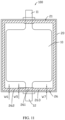
FIG. 1 is a schematic diagram of a cross section of an electrochemical device according to an embodiment of this application. -
FIG. 2 is a local enlarged view of the electrochemical apparatus inFIG. 1 at position II in an embodiment. -
FIG. 3 is a local enlarged view of the electrochemical apparatus inFIG. 1 at position II in another embodiment. -
FIG. 4 is a local enlarged view of the electrochemical apparatus inFIG. 1 at position II in still another embodiment. -
FIG. 5 is a local enlarged view of a second sealing zone of the electrochemical apparatus inFIG. 1 in an embodiment. -
FIG. 6 is a local enlarged view of a second sealing zone of the electrochemical apparatus inFIG. 1 in another embodiment. -
FIG. 7A is a schematic diagram of a cross section of the electrochemical apparatus shown inFIG. 2 along VIIA-VIIA. -
FIG. 7B is a schematic diagram of a cross section of the electrochemical apparatus shown inFIG. 2 along VIIB-VIIB in an embodiment. -
FIG. 8 is a schematic diagram of a cross section of the electrochemical apparatus shown inFIG. 2 along VIIB-VIIB in another embodiment. -
FIG. 9 is a schematic diagram of a cross section of the electrochemical apparatus shown inFIG. 2 along VIIB-VIIB in still another embodiment. -
FIG. 10 is a schematic diagram of a cross section of the electrochemical apparatus shown inFIG. 2 along X-X. -
FIG. 11 is a schematic diagram of a cross section of an electrochemical apparatus according to another embodiment of this application. -
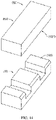
FIG. 12 is a schematic structural diagram of a packaging seal head for sealing an electrochemical apparatus according to an embodiment of this application. -
FIG. 13 is a schematic structural diagram of a packaging seal head for sealing an electrochemical apparatus according to another embodiment of this application. -
FIG. 14 is a schematic structural diagram of a packaging seal head for sealing an electrochemical apparatus according to still another embodiment of this application. -
FIG. 15 is a schematic structural diagram of a packaging seal head for sealing an electrochemical apparatus according to yet still another embodiment of this application. -
FIG. 16 is a schematic structural diagram of an electronic apparatus according to an embodiment of this application. - Reference signs of main components:
Electrode assembly 10 First tab 11 Second tab 12 Tab sealant 13 Packaging film 20 First packaging film 20a Second packaging film 20b First sealing zone 21 Second sealing zone 22 First non-sealing zone 23 Second non-sealing zone 24 Overflow adhesive groove 25 Third sealing zone 26 Electrochemical apparatus 100 Packaging seal head 200 First seal head 201 Second seal head 202 First region 211, 211' Second region 212, 212' Third region 213, 213' Fourth region 214 First connecting portion 231 Second connecting portion 232 Third connecting portion 241 Fourth connecting portion 242 Fifth region 261 Sixth region 262 Seventh region 263 Electronic apparatus 300 First end face 2010 First end face area 2011 Second end face area 2012 Third end face area 2013 Fourth end face area 2014 Chamfered face 2015 Second end face 2020 Width Wi, W1', W2, W2', W3, W3', W4, w5, W6, W7 Thickness T1, T2, T3 Distance D - This application will be further described with reference to the accompanying drawings in the following specific embodiments.
- The following clearly and completely describes the technical solutions in the embodiments of this application with reference to the accompanying drawings in the embodiments of this application. Apparently, the described embodiments are only some rather than all of the embodiments of this application. All other embodiments obtained by a person of ordinary skill in the art based on the examples of this application without creative efforts shall fall within the protection scope of this application.
- Unless otherwise defined, all technical and scientific terms used herein shall have the same meanings as commonly understood by those skilled in the art to which this application belongs. The terms used herein in the specification of this application are merely intended to describe specific embodiments but not intended to limit this application.
- The following describes in detail some embodiments of this application with reference to the accompanying drawings. In absence of conflicts, the following embodiments and features in the embodiments may be combined.
- Referring to
FIG. 1 , an embodiment of this application provides anelectrochemical apparatus 100 including anelectrode assembly 10, apackaging film 20, and afirst tab 11, where thefirst tab 11 is electrically connected to theelectrode assembly 10. Thepackaging film 20 includes afirst packaging film 20a and asecond packaging film 20b (shown inFIG. 7A ) which are located at two sides of thefirst tab 11. Thefirst packaging film 20a includes afirst sealing zone 21 and thesecond packaging film 20b includes asecond sealing zone 22, where thefirst sealing zone 21 and thesecond sealing zone 22 are bonded to seal theelectrode assembly 10. - The
first sealing zone 21 includes afirst region 211 and asecond region 212, where thefirst region 211 covers a projection of thefirst tab 11 on thefirst sealing zone 21 and thesecond region 212 connects to thefirst region 211. Also referring toFIG. 2 , a width W2 of thesecond region 212 is less than a width W1 of thefirst region 211. The width W1 is defined as a size of thefirst region 211 in an extension direction of thefirst sealing zone 21 and the width W2 is defined as a size of thesecond region 212 in the extension direction of thefirst sealing zone 21. - The
electrochemical apparatus 100 in this application includes all apparatuses capable of electrochemical reactions. Specifically, theelectrochemical apparatus 100 includes all kinds of primary batteries, secondary batteries, fuel batteries, solar batteries, and capacitors (for example, super capacitors). Optionally, theelectrochemical apparatus 100 may be a secondary lithium battery, including a secondary lithium metal battery, a secondary lithium-ion battery, a secondary lithium polymer battery, or a secondary lithium-ion polymer battery. - The bonding of the
first sealing zone 21 and thesecond sealing zone 22 may be a press fit of thefirst packaging film 20a and thesecond packaging film 20b via a packaging seal head, so that polypropylene layers in the part offirst packaging film 20a and the part ofsecond packaging film 20b (that is, thefirst sealing zone 21 and the second sealing zone 22) located at a press fit position undergo a thermal fusion so as to bond thefirst sealing zone 21 and thesecond sealing zone 22 for sealing. Optionally, the manner of bonding thefirst sealing zone 21 and thesecond zone 22 for sealing is not limited thereto, but may be thermal fusion of other materials or other forms of fusion. - The
second region 212 may be located on any side of thefirst region 211 and this application is not limited in this sense. As shown inFIG. 1 , thesecond region 212 is located on the left side of thefirst region 211. However, in other embodiments, thesecond region 212 may further be located on the right side of thefirst region 211. - The position where the
first tab 11 is located is often a packaging weakness point, and excessive overflow adhesive may cause fatigue cracks in thepackaging film 20 at the sealing position under abuse of external force, bringing about electrolyte leakage. According to this application, the width of thesecond region 212 is set to be less than that of thefirst region 211, thus retaining the sealing width at thefirst tab 11 while reducing the sealing width at one side of thefirst tab 11. In this way, the sealing strength at thefirst tab 11 remains unchanged while a position where thesecond region 212 has a width difference with respect to thefirst region 211 can be a space for accommodating the overflow adhesive, thereby alleviating the problem of adhesive overflow and reducing stress concentration points. Therefore, safety performance and service life of theelectrochemical apparatus 100 can be improved. - In an embodiment, the width W2 of the
second region 212 is 40%-95% of the width W1 of the first region 211 (that is, 40% W1≤W2≤95% W1). The inventor of this application has found that when the ratio of W2 to W1 is less than 40%, the width W2 of thesecond region 212 is excessively small, which impacts the packaging strength, thereby impacting life of the package. On the contrary, when the ratio of W2 to W1 is greater than 95%, enough space is not available for accommodating the overflow adhesive, so that adhesive overflow is not desirably alleviated. - In an embodiment, as shown in
FIG. 1 andFIG. 2 , thefirst sealing zone 21 further includes athird region 213, where thefirst region 211 connects thesecond region 212 and thethird region 213. A width W3 of thethird region 213 is less than the width W1 of thefirst region 211. The width W3 is defined as a size of thethird region 213 in the extension direction of thefirst sealing zone 21. - As shown in
FIG. 2 , in an embodiment, the width of thesecond region 212 and the width of thethird region 213 are both less than the width of thefirst region 211 and the width of thesecond region 212 is equal to that of the third region 213 (that is, W2=W3<W1). In this case, space for accommodating overflow adhesive is formed on both sides of thefirst tab 11. As shown inFIG. 3 , in another embodiment, the width of thesecond region 212 and the width of thethird region 213 are both less than the width of thefirst region 211 and the width of thesecond region 212 is alternatively different from that of thethird region 213. For example, the width of thesecond region 212 may be greater than that of the third region 213 (that is W3<W2<W1). - Furthermore, the width W3 of the
third region 213 may also be 40%-95% of the width of the first region 211 (that is, 40% W1≤W3≤95% W1). The inventor of this application has found that when the ratio of W3 to W1 is less 40%, the width of thethird region 213 is excessively small, which impacts the packaging strength, thereby impacting life of the package. On the contrary, when the ratio of W3 to W1 is greater than 95%, enough space is not available for accommodating the overflow adhesive, so that adhesive overflow is not desirably alleviated. - As shown in
FIG. 4 , in still another embodiment, the width of thethird region 213 may further be equal to that of the first region 211 (that is, W2<W1=W3). In this case, space for accommodating overflow adhesive is formed on only one side of thefirst tab 11. - Referring to
FIG. 1 andFIG. 5 together, in this embodiment, the shape of thesecond sealing zone 22 matches that of thefirst sealing zone 21. That is, thesecond sealing zone 22 includes a first region 211', a second region 212', and a third region 213', where the first region 211' covers a projection of thefirst tab 11 on thesecond sealing zone 22 and the first region 211' connects the second region 212' and the third region 213'. A width W2' of the second region 212' is less than the width W1' of the first region 211'. Furthermore, a width W3' of the third region 213' may also be less than the width W1' of the first region 211'. - As shown in
FIG. 6 , in other embodiments, thesecond sealing zone 22 may alternatively have no width difference. That is, the first region 211', the second region 212', and the third region 213' all have the same width (W1'=W2'=W3'). - As shown in
FIG. 7A and FIG. 7B , in this embodiment, thefirst packaging film 20a further includes a firstnon-sealing zone 23. The firstnon-sealing zone 23 includes the first connectingportion 231 and the second connectingportion 232, where the first connectingportion 231 connects thefirst sealing zone 21 and the second connectingportion 232. In a thickness direction of thepackaging film 20, an angle between the first connectingportion 231 and thefirst sealing zone 21 is greater than 0° and less than or equal to 90°, which means the first connectingportion 231 is not parallel to thefirst sealing zone 21. The thickness direction of thepackaging film 20 is defined as a direction perpendicular to a plane where thefirst packaging film 20a or thesecond packaging film 20b is located. - In this way, an overflow
adhesive groove 25 is formed between the firstnon-sealing zone 23 and thesecond packaging film 20b, where the overflowadhesive groove 25 can be used to accommodate the overflow adhesive. With the overflowadhesive groove 25 accommodating overflow adhesive, if the overflow adhesive exhibits a morphology protruding towards theelectrode assembly 10, thepackaging film 20 will have stress concentration points at the adhesive overflow locations. The overflowadhesive groove 25 of this application provides enough space for accommodating the overflow adhesive so that the overflow adhesive protrudes towards the first sealing zone 21 (this is, recessed towards the electrode assembly 10), preventing thepackaging film 20 from having stress concentration points at the adhesive overflow locations. - Furthermore, the
second packaging film 20b further includes a secondnon-sealing zone 24. The secondnon-sealing zone 24 includes a third connecting portion 241 and a fourth connecting portion 242, where the third connecting portion 241 connects thesecond sealing zone 22 and the fourth connecting portion 242. In the thickness direction of thepackaging film 20, an angle between the third connecting portion 241 and thesecond sealing zone 22 is greater than 0° and less than or equal to 90°, which means the third connecting portion 241 is not parallel to thesecond sealing zone 22. In this way, the overflowadhesive groove 25 can have a greater space to accommodate more overflow adhesive. - As shown in
FIG. 7A and FIG. 7B , the angle between the first connectingportion 231 and thefirst sealing zone 21 is less than 90 degrees and the angle between the third connecting portion 241 and thesecond sealing zone 22 is less than 90 degrees. In addition, the first connectingportion 231 and the third connecting portion 241 are both planar. In other embodiments, the angle between the first connectingportion 231 and thefirst sealing zone 21 and the angle between the third connecting portion 241 and thesecond sealing zone 22 may be changed based on actual needs. For example, as shown inFIG. 8 , the angle between the first connectingportion 231 and thefirst sealing zone 21 may be equal to 90 degrees and the angle between the third connecting portion 241 and thesecond sealing zone 22 may be equal to 90 degrees. Certainly, the first connectingportion 231 and the third connecting portion 241 may alternatively be a curved surface, a stepped surface, or other shapes. - As shown in
FIG. 9 , in other embodiments, when thesecond sealing zone 22 has no width difference, the third connecting portion 241 and the fourth connecting portion 242 of the secondnon-sealing zone 24 are both located at the same plane as thesecond sealing zone 22. - As shown in
FIG. 7A , in this embodiment, thesecond region 212 and thesecond sealing zone 22 together form a thickness T2 (mm) and a distance between the second connectingportion 232 and the fourth connecting portion 242 is D (mm), where T2<D≤10T2. The inventor of this application has found that this range helps to guarantee the packaging strength and sealing effect of thesecond region 212 and thesecond sealing zone 22. The distance D being greater than 10T2 means an excessive amount of overflow adhesive, an over-sealed sealing zone, and over-fused polymer film in thepackaging film 20. On the contrary, the distance D being less than or equal to T2 means that the overflow adhesive at the sealing zone is not completely fused, in which case, the sealing is not firm. - As shown in
FIG. 7B , further, thethird region 213 and thesecond sealing zone 22 together form a thickness T3 (mm), where T3<D≤10T3. The inventor of this application has found that this range can guarantee the packaging strength and sealing effect of thethird region 213 and thesecond sealing zone 22. The distance D being greater than 10T3 means an excessive amount of overflow adhesive, an over-sealed sealing zone, and over-fused polymer film in thepackaging film 20. On the contrary, the distance D being less than or equal to T3 means that the overflow adhesive at the sealing zone is not completely fused, in which case, the sealing is not firm. - As shown in
FIG. 7A andFIG. 10 , even further, thefirst region 211 and thesecond sealing zone 22 form a thickness T1 (mm), where T2<T1≤4T2. Therefore, the packaging strength at thefirst region 211 can be consistent with that at thesecond region 212, guaranteeing an overall packaging effect and avoiding local packaging weaknesses. The thickness T1 formed by thefirst region 211 and thesecond sealing zone 22 should also include thickness of thefirst tab 11 and atab sealant 13 on a surface of thefirst tab 11. - In this embodiment, a packaging tension between the
first sealing zone 21 and thesecond sealing zone 22 is 1 N/mm-10 N/mm. The packaging tension may be used to characterize the packaging strength and effect. The packaging tension being less than 1 N/mm means inadequate packaging strength whereas 10 N/mm is the tension limit of conventional packaging films and the packaging tension being within 10 N/mm means the tension limit of thepackaging film 20 is not exceeded. - As shown in
FIG. 1 , in this embodiment, theelectrochemical apparatus 100 further includes asecond tab 12, where thesecond tab 12 is electrically connected to theelectrode assembly 10 and thesecond tab 12 is located on the same side of theelectrode assembly 10 as thefirst tab 11. Thefirst sealing zone 21 further includes afourth region 214, where thefourth region 214 covers a projection of thesecond tab 12 on thefirst sealing zone 21 and thesecond region 212 connects to thefourth region 214. Thefourth region 214 and thefirst region 211 share the same width. A width of thefourth region 214 is defined as W4, where W4=W1. - As shown in
FIG. 11 , in another embodiment, thesecond tab 12 is located on a different side of theelectrode assembly 10 than thefirst tab 11. For example, thefirst tab 11 and thesecond tab 12 are respectively located on two opposite sides of theelectrode assembly 10. Thefirst packaging film 20a further includes athird sealing zone 26, where thethird sealing zone 26 includes afifth region 261, asixth region 262, and aseventh region 263, thefifth region 261 covers a projection of thesecond tab 12 on thethird sealing zone 26, and thefifth region 261 connects between thesixth region 262 and theseventh region 263. A width of thesixth region 262 is less than that of thefifth region 261. - Furthermore, a width of the
seventh region 263 may also be less than that of thefifth region 261. The width of thefifth region 261 is defined as W5, that of thesixth region 262 as W6, and that of theseventh region 263 as W7, where at least one of W6 and W7 is less than W5. - As shown in
FIG. 12 , apackaging seal head 200 for sealing theelectrochemical apparatus 100 according to an embodiment of this application is provided. Thepackaging seal head 200 includes afirst seal head 201 and asecond seal head 202 corresponding to thefirst seal head 201. Thefirst seal head 201 includes afirst end face 2010 facing thesecond seal head 202 and thesecond seal head 202 includes asecond end face 2020 facing thefirst seal head 201. - At least one of the
first end face 2010 and thesecond end face 2020 includes a firstend face area 2011 corresponding to thefirst region 211, a secondend face area 2012 corresponding to thesecond region 212, and a thirdend face area 2013 corresponding to thethird region 213, where the firstend face area 2011 is recessed with respect to the secondend face area 2012 and the third end face area 2013 (which means a slot is formed). A chamferedface 2015 is included at an edge of the secondend face area 2012 facing theelectrode assembly 10. - Furthermore, a chamfered
face 2015 may also be included in at an edge of the thirdend face area 2013 facing theelectrode assembly 10 - According to this application, with the second
end face area 2012 provided with the chamferedface 2015, after thepackaging seal head 200 is applied to seal theelectrochemical apparatus 100, the chamferedface 2015 enables thesecond region 212 of thefirst sealing zone 21 to have a width difference with respect to thefirst region 211, so that a space for accommodating the overflow adhesive is formed. - It can be understood that the shape of the chamfered
face 2015 determines an included angle between the first connectingportion 231 and the second connectingportion 232, an included angle between the third connecting portion 241 and the fourth connecting portion 242, shapes of the first connectingportion 231 and the third connecting portion 241, and the like. For example, with the chamferedface 2015 of the secondend face area 2012 being an inclined plane, the first connectingportion 231 is also planar. With the chamferedface 2015 of the secondend face area 2012 being a curved surface, the first connectingportion 231 is also a curved surface. Certainly, in other embodiments, the chamferedface 2015 may alternatively be in a stepped shape or in other shapes. - As shown in
FIG. 12 , in this embodiment, thefirst end face 2010 matches thesecond end face 2020. Thefirst end face 2010 and thesecond end face 2020 both include a firstend face area 2011, a secondend face area 2012, and a thirdend face area 2013. The secondend face area 2012 and the thirdend face area 2013 of thefirst end face 2010 both include a chamferedface 2015 and the secondend face area 2012 of thesecond end face 2020 includes a chamferedface 2015. - Furthermore, the third
end face area 2013 also includes a chamferedface 2015. After thepackaging seal head 200 is applied to seal theelectrochemical apparatus 100, both the width of thesecond region 212 and that of thethird region 213 are less than that of thefirst region 211. - More specifically, the
first end face 2010 and thesecond end face 2020 further both include a fourthend face area 2014 corresponding to thefourth region 214. The fourthend face area 2014 is also recessed with respect to the secondend face area 2012 and the thirdend face area 2013. That is, thefirst end face 2010 and thesecond end face 2020 both include two slots, where two slots respectively correspond to thefirst tab 11 and thesecond tab 12 of theelectrochemical apparatus 100. In this case, thepackaging seal head 200 can be used to seal anelectrochemical apparatus 100 with thefirst tab 11 and thesecond tab 12 located on the same side of theelectrode assembly 10. The chamfered faces 2015 of the secondend face area 2012 and the thirdend face area 2013 of thefirst end face 2010 have equal sizes. Correspondingly, in theelectrochemical apparatus 100, the width of thesecond region 212 is equal to that of the third region 213 (that is, W2=W3). - As shown in
FIG. 13 , in another embodiment, the chamfered faces 2015 of the secondend face area 2012 and the thirdend face area 2013 of thefirst end face 2010 have different sizes. Correspondingly, in theelectrochemical apparatus 100, the width of thesecond region 212 is different from that of thethird region 213. For example, the width of thesecond region 212 is greater than that of the third region 213 (that is, W3<W2). - As shown in
FIG. 14 , in still another embodiment, thefirst end face 2010 may not match thesecond end face 2020. For example, thefirst end face 2010 is not provided with a slot and is not provided with the first end face are 2011, the secondend face area 2012, or the thirdend face area 2013. Correspondingly, in theelectrochemical apparatus 100, thesecond sealing zone 22 does not have a width difference. - As shown in
FIG. 15 , in yet still another embodiment, thefirst end face 2010 and thesecond end face 2020 both include only one slot. Correspondingly, thepackaging seal head 200 can be used to seal anelectrochemical apparatus 100 with thefirst tab 11 and thesecond tab 12 located on different sides of theelectrode assembly 10. - An embodiment of this application further provides an
electronic apparatus 300, where theelectronic apparatus 300 includes anelectrochemical apparatus 100. Theelectronic apparatus 300 may be a consumer electronic product (such as a mobile communications apparatus, a tablet computer, or a laptop computer), an electric tool, an unmanned aerial vehicle, an energy storage apparatus, a traction apparatus, or the like. Referring toFIG. 16 , in an embodiment, theelectronic apparatus 300 is a mobile communications apparatus. - In conclusion, it should be noted that the foregoing embodiments are merely intended to describe the technical solutions of this application, but not intended to constitute any limitation. Although this application is described in detail with reference to preferred embodiments, persons of ordinary skill in the art should understand that modifications or equivalent replacements can be made to the technical solutions of this application without departing from the spirit and scope of the technical solutions of this application.
Claims (10)
- An electrochemical apparatus comprising an electrode assembly, a packaging film and a first tab, wherein the first tab is electrically connected to the electrode assembly, the packaging film comprises a first packaging film and a second packaging film which are located at two sides of the first tab, the first packaging film comprises a first sealing zone, the second packaging film comprises a second sealing zone, and the first sealing zone and the second sealing zone are bonded to seal the electrode assembly, wherein
the first sealing zone comprises a first region and a second region, the first region covers a projection of the first tab on the first sealing zone, the second region connects to the first region, and a width of the second region is less than that of the first region. - The electrochemical apparatus according to claim 1, wherein the width of the second region is 40%-95% of that of the first region.
- The electrochemical apparatus according to claim 1, wherein the first packaging film further comprises a first non-sealing zone, the first non-sealing zone comprises a first connecting portion and a second connecting portion, wherein the first connecting portion connects the first sealing zone and the second connecting portion, in a thickness direction of the packaging film, an angle between the first connecting portion and the first sealing zone is greater than 0° and less than or equal to 90°.
- The electrochemical apparatus according to claim 3, wherein the second packaging film further comprises a second non-sealing zone, the second non-sealing zone comprises a third connecting portion and a fourth connecting portion, wherein the third connecting portion connects the second sealing zone and the fourth connecting portion, in the thickness direction of the packaging film, an angle between the third connecting portion and the second sealing zone is greater than 0° and less than or equal to 90°.
- The electrochemical apparatus according to claim 4, wherein the second region and the second sealing zone together form a thickness T2 (mm) and a distance between the second connecting portion and the fourth connecting portion is D (mm), wherein T2<D≤10T2.
- The electrochemical apparatus according to claim 5, wherein the first region and the second sealing zone form a thickness T1 (mm), wherein T2<T1≤4T2.
- The electrochemical apparatus according to claim 1, wherein a packaging tension between the first sealing zone and the second sealing zone is 1 N/mm-10 N/mm.
- The electrochemical apparatus according to claim 1, wherein the electrochemical apparatus further comprises a second tab, wherein the second tab is electrically connected to the electrode assembly, the second tab is located on the same side of the electrode assembly as the first tab; and
the first sealing zone further comprises a third region, wherein the third region covers a projection of the second tab on the first sealing zone, the second region connects to the third region, and a width of the third region is the same as that of the first region. - The electrochemical apparatus according to claim 1, wherein the electrochemical apparatus further comprises a second tab, wherein the second tab is electrically connected to the electrode assembly, the second tab is located on a different side of the electrode assembly than the first tab; and
the first packaging film further comprises a third sealing zone, wherein the third sealing zone comprises a fourth region and a fifth region, the fourth region covers a projection of the second tab on the third sealing zone, the fifth region connects to the fourth region, and a width of the fifth region is less than that of the fourth region. - An electronic apparatus, comprising the electrochemical apparatus according to any one of claims 1 to 9.
Applications Claiming Priority (1)
| Application Number | Priority Date | Filing Date | Title |
|---|---|---|---|
| PCT/CN2020/080968 WO2021189264A1 (en) | 2020-03-24 | 2020-03-24 | Electrochemical device and electronic device |
Publications (2)
| Publication Number | Publication Date |
|---|---|
| EP4142023A1 true EP4142023A1 (en) | 2023-03-01 |
| EP4142023A4 EP4142023A4 (en) | 2023-10-25 |
Family
ID=77890878
Family Applications (1)
| Application Number | Title | Priority Date | Filing Date |
|---|---|---|---|
| EP20927304.4A Pending EP4142023A4 (en) | 2020-03-24 | 2020-03-24 | ELECTROCHEMICAL DEVICE AND ELECTRONIC DEVICE |
Country Status (5)
| Country | Link |
|---|---|
| US (1) | US20230013955A1 (en) |
| EP (1) | EP4142023A4 (en) |
| KR (1) | KR102913522B1 (en) |
| CN (1) | CN113597702B (en) |
| WO (1) | WO2021189264A1 (en) |
Cited By (1)
| Publication number | Priority date | Publication date | Assignee | Title |
|---|---|---|---|---|
| EP4307415A4 (en) * | 2021-04-09 | 2024-10-23 | Ningde Amperex Technology Ltd. | BATTERY CELL AND ELECTRICAL DEVICE |
Families Citing this family (4)
| Publication number | Priority date | Publication date | Assignee | Title |
|---|---|---|---|---|
| KR102921535B1 (en) * | 2022-02-08 | 2026-02-03 | 주식회사 엘지에너지솔루션 | Battery case, battery case forming apparatus and secondary battery manufacturing method |
| CN114614174A (en) * | 2022-03-29 | 2022-06-10 | 东莞新能安科技有限公司 | Battery case, battery and electronic device |
| WO2023197160A1 (en) * | 2022-04-12 | 2023-10-19 | 宁德新能源科技有限公司 | Electrochemical apparatus and electronic device |
| CN218548600U (en) * | 2022-10-31 | 2023-02-28 | 珠海冠宇电池股份有限公司 | Battery cell and battery |
Family Cites Families (14)
| Publication number | Priority date | Publication date | Assignee | Title |
|---|---|---|---|---|
| KR101572014B1 (en) * | 2007-11-30 | 2015-11-26 | 에이일이삼 시스템즈 인코포레이티드 | Battery cell design with asymmetrical terminals |
| KR101254691B1 (en) * | 2010-08-17 | 2013-04-15 | 주식회사 엘지화학 | Secondary electric cell with enhanced lead structure |
| KR101200469B1 (en) * | 2010-12-07 | 2012-11-12 | 주식회사 엘지화학 | Secondary battery having differential sealing width |
| JP5693327B2 (en) * | 2011-03-29 | 2015-04-01 | Fdk鳥取株式会社 | Method for producing electrochemical element |
| WO2014104728A1 (en) * | 2012-12-24 | 2014-07-03 | 주식회사 엘지화학 | Pouch-type secondary battery having sealing margin for improved durability |
| CN204614821U (en) * | 2015-04-02 | 2015-09-02 | 宁德新能源科技有限公司 | Electrochemical energy storage device encapsulating structure and packaging system thereof |
| KR101933655B1 (en) * | 2015-07-28 | 2018-12-28 | 주식회사 엘지화학 | Battery Cell Having Recess Portion Formed at Portion of Electrode Tab |
| CN108886126B (en) * | 2016-01-06 | 2021-11-26 | 宁德新能源科技有限公司 | Secondary battery |
| CN106252578B (en) * | 2016-10-31 | 2019-01-08 | 宁德时代新能源科技股份有限公司 | Utmost point ear packaging structure and laminate polymer battery |
| JP2019087336A (en) * | 2017-11-02 | 2019-06-06 | 積水化学工業株式会社 | Secondary battery |
| CN207852828U (en) * | 2018-02-10 | 2018-09-11 | 微宏动力系统(湖州)有限公司 | A kind of soft pack cell |
| CN208000939U (en) * | 2018-04-11 | 2018-10-23 | 宁德新能源科技有限公司 | Battery and equipment |
| JP2020053121A (en) * | 2018-09-21 | 2020-04-02 | 積水化学工業株式会社 | Lamination type battery and manufacturing method of lamination type battery |
| CN209496945U (en) * | 2019-01-15 | 2019-10-15 | 东莞新能源科技有限公司 | Battery cell and battery |
-
2020
- 2020-03-24 CN CN202080015556.1A patent/CN113597702B/en active Active
- 2020-03-24 KR KR1020227035182A patent/KR102913522B1/en active Active
- 2020-03-24 EP EP20927304.4A patent/EP4142023A4/en active Pending
- 2020-03-24 WO PCT/CN2020/080968 patent/WO2021189264A1/en not_active Ceased
-
2022
- 2022-09-23 US US17/951,159 patent/US20230013955A1/en active Pending
Cited By (1)
| Publication number | Priority date | Publication date | Assignee | Title |
|---|---|---|---|---|
| EP4307415A4 (en) * | 2021-04-09 | 2024-10-23 | Ningde Amperex Technology Ltd. | BATTERY CELL AND ELECTRICAL DEVICE |
Also Published As
| Publication number | Publication date |
|---|---|
| US20230013955A1 (en) | 2023-01-19 |
| CN113597702B (en) | 2023-01-24 |
| CN113597702A (en) | 2021-11-02 |
| KR20220145410A (en) | 2022-10-28 |
| KR102913522B1 (en) | 2026-01-16 |
| WO2021189264A1 (en) | 2021-09-30 |
| EP4142023A4 (en) | 2023-10-25 |
Similar Documents
| Publication | Publication Date | Title |
|---|---|---|
| US20230013955A1 (en) | Electrochemical apparatus and electronic apparatus | |
| US20230344019A1 (en) | Electrode assembly and electrochemical apparatus | |
| US7396613B2 (en) | Battery pack and method for producing same | |
| EP3800690B1 (en) | Secondary battery | |
| US20210143503A1 (en) | Pouch Case and the Method of Manufacturing the Pouch Type Secondary Battery Including the Same | |
| US20250323356A1 (en) | Battery cell, secondary battery, and electric device | |
| KR20140103402A (en) | Pouch for battery, and pouch type battery including the same | |
| JP7482248B2 (en) | Battery cell and electrochemical device using the same | |
| JP4304304B2 (en) | Film outer battery | |
| US20220399616A1 (en) | Electrochemical device and electronic device | |
| US20230207933A1 (en) | Secondary Battery and Method for Manufacturing the Same, and Battery Pack | |
| JP2001060452A (en) | Method of manufacturing film-covered battery | |
| KR20220043024A (en) | Pouch battery cell and battery module including the same | |
| CN212011123U (en) | Liquid leakage prevention tab of soft package lithium ion battery cell | |
| KR102252335B1 (en) | Pouch-typed Battery Cell Having Extended Protective Film | |
| KR102799380B1 (en) | Outer package and battery | |
| CN218039746U (en) | Anti-leakage battery tab | |
| KR20200109147A (en) | Pouch-type secondary battery and battery module having thereof | |
| KR100731436B1 (en) | Pouch Type Lithium Secondary Battery | |
| KR102082655B1 (en) | Method Preparing Electrode Assembly Having Corner Cutting Structure and Electrode Assembly Prepared Using the Same | |
| US12620658B2 (en) | Pouch battery cell and battery module including the same | |
| US20260135280A1 (en) | Secondary battery and method for manufacturing same | |
| CN214043756U (en) | Soft packet of lithium ion battery circular arc encapsulation head of button | |
| KR20240033463A (en) | Battery cell and battery module including the same | |
| US20240291093A1 (en) | Battery pack and method of manufacturing same |
Legal Events
| Date | Code | Title | Description |
|---|---|---|---|
| STAA | Information on the status of an ep patent application or granted ep patent |
Free format text: STATUS: THE INTERNATIONAL PUBLICATION HAS BEEN MADE |
|
| PUAI | Public reference made under article 153(3) epc to a published international application that has entered the european phase |
Free format text: ORIGINAL CODE: 0009012 |
|
| STAA | Information on the status of an ep patent application or granted ep patent |
Free format text: STATUS: REQUEST FOR EXAMINATION WAS MADE |
|
| 17P | Request for examination filed |
Effective date: 20220930 |
|
| AK | Designated contracting states |
Kind code of ref document: A1 Designated state(s): AL AT BE BG CH CY CZ DE DK EE ES FI FR GB GR HR HU IE IS IT LI LT LU LV MC MK MT NL NO PL PT RO RS SE SI SK SM TR |
|
| DAV | Request for validation of the european patent (deleted) | ||
| DAX | Request for extension of the european patent (deleted) | ||
| REG | Reference to a national code |
Ref country code: DE Ref legal event code: R079 Free format text: PREVIOUS MAIN CLASS: H01M0050100000 Ipc: H01M0050105000 |
|
| A4 | Supplementary search report drawn up and despatched |
Effective date: 20230921 |
|
| RIC1 | Information provided on ipc code assigned before grant |
Ipc: H01M 50/534 20210101ALI20230915BHEP Ipc: H01M 50/533 20210101ALI20230915BHEP Ipc: H01M 50/188 20210101ALI20230915BHEP Ipc: H01M 50/131 20210101ALI20230915BHEP Ipc: H01G 11/80 20130101ALI20230915BHEP Ipc: H01G 11/78 20130101ALI20230915BHEP Ipc: H01G 11/74 20130101ALI20230915BHEP Ipc: H01M 50/105 20210101AFI20230915BHEP |
|
| RAP1 | Party data changed (applicant data changed or rights of an application transferred) |
Owner name: NINGDE AMPEREX TECHNOLOGY LIMITED |
|
| RAP3 | Party data changed (applicant data changed or rights of an application transferred) |
Owner name: NINGDE AMPEREX TECHNOLOGY LIMITED |