EP4141853A1 - Safety triangle - Google Patents
Safety triangle Download PDFInfo
- Publication number
- EP4141853A1 EP4141853A1 EP22185109.0A EP22185109A EP4141853A1 EP 4141853 A1 EP4141853 A1 EP 4141853A1 EP 22185109 A EP22185109 A EP 22185109A EP 4141853 A1 EP4141853 A1 EP 4141853A1
- Authority
- EP
- European Patent Office
- Prior art keywords
- frame
- safety device
- illumination
- sockets
- rods
- Prior art date
- Legal status (The legal status is an assumption and is not a legal conclusion. Google has not performed a legal analysis and makes no representation as to the accuracy of the status listed.)
- Withdrawn
Links
Images







Classifications
-
- G—PHYSICS
- G09—EDUCATION; CRYPTOGRAPHY; DISPLAY; ADVERTISING; SEALS
- G09F—DISPLAYING; ADVERTISING; SIGNS; LABELS OR NAME-PLATES; SEALS
- G09F13/00—Illuminated signs; Luminous advertising
- G09F13/24—Illuminated signs; Luminous advertising using tubes or the like filled with liquid, e.g. bubbling liquid
-
- B—PERFORMING OPERATIONS; TRANSPORTING
- B60—VEHICLES IN GENERAL
- B60Q—ARRANGEMENT OF SIGNALLING OR LIGHTING DEVICES, THE MOUNTING OR SUPPORTING THEREOF OR CIRCUITS THEREFOR, FOR VEHICLES IN GENERAL
- B60Q7/00—Arrangement or adaptation of portable emergency signal devices on vehicles
-
- G—PHYSICS
- G09—EDUCATION; CRYPTOGRAPHY; DISPLAY; ADVERTISING; SEALS
- G09F—DISPLAYING; ADVERTISING; SIGNS; LABELS OR NAME-PLATES; SEALS
- G09F13/00—Illuminated signs; Luminous advertising
- G09F13/20—Illuminated signs; Luminous advertising with luminescent surfaces or parts
- G09F13/22—Illuminated signs; Luminous advertising with luminescent surfaces or parts electroluminescent
-
- G—PHYSICS
- G09—EDUCATION; CRYPTOGRAPHY; DISPLAY; ADVERTISING; SEALS
- G09F—DISPLAYING; ADVERTISING; SIGNS; LABELS OR NAME-PLATES; SEALS
- G09F13/00—Illuminated signs; Luminous advertising
- G09F13/20—Illuminated signs; Luminous advertising with luminescent surfaces or parts
- G09F13/22—Illuminated signs; Luminous advertising with luminescent surfaces or parts electroluminescent
- G09F2013/222—Illuminated signs; Luminous advertising with luminescent surfaces or parts electroluminescent with LEDs
-
- G—PHYSICS
- G09—EDUCATION; CRYPTOGRAPHY; DISPLAY; ADVERTISING; SEALS
- G09F—DISPLAYING; ADVERTISING; SIGNS; LABELS OR NAME-PLATES; SEALS
- G09F13/00—Illuminated signs; Luminous advertising
- G09F13/20—Illuminated signs; Luminous advertising with luminescent surfaces or parts
- G09F13/22—Illuminated signs; Luminous advertising with luminescent surfaces or parts electroluminescent
- G09F2013/227—Electroluminescent displays for vehicles
Definitions
- the invention relates to a safety triangle for use in automotive and other applications where improved visibility creates a safer environment.
- High visibility safety devices for automotive, construction and similar applications may include reflective triangles, flares, flashlights, strobes and similar devices. Such devices are often limited in their effectiveness by size, visibility, lack of fresh batteries, and other limitations.
- a high visibility safety device is provided, such as can be stored in a vehicle and displayed to indicate caution or emergencies.
- the safety device of embodiments includes one or more illumination rods.
- the one or more illumination rods form an illuminated beacon, such as a safety triangle.
- a single illumination rod can be used, but preferably two or three illumination rods are used to form a partial or full triangle or a pyramidal shape.
- the illumination rods can be battery powered LED or other light bars, but are preferably each a self-contained, short-term light-source such as a glow stick.
- Suitable glow sticks also known as light sticks, chem lights, light wands, or light rods, are generally formed of a translucent plastic tube containing isolated substances that, when combined, make light through chemiluminescence.
- the safety device includes a frame having one or more sockets each compatible with a first end of an illumination rod, such that when one or more illumination rod are engaged with the one or more sockets, a standable illuminated frame is enabled.
- the illumination rods can be vertical extensions from the frame, with free ends facing upwards from a frame base, or downwards as legs for a tripodic, or pyramidal device.
- a horizonal rod can be used to complete a three-sided illuminated triangle.
- a safety triangle as disclosed preferably includes a small and/or foldable frame having a plurality of sockets that assemble with standard size glow sticks of the kind that use a reactive fluorescing composition that glows once the glow stick is partially bent and/or otherwise activated.
- the safety device includes at least two sockets, each compatible with one end of an illumination rod.
- a second end of at least two of the illumination rods is a free end configured to extend upward or set upon a surface.
- the illumination rod can be held in the socket by friction, threads, or any other suitable means.
- the safety device includes a tripodic frame including the one or more sockets and any other leg(s) extending at an angle to each other.
- the device can include three legs in an assembled configuration, with one, two or all three of the legs being an illumination rod.
- the device includes non-illumination legs or extensions, either fixed or attachable to the socket frame.
- the frame can include one or more foldable hinges, such as between socket pairs or one for each moveable socket, for folding the device and reducing a storage footprint.
- the hinge may be particularly useful for non-illuminating frame legs, or for storing a preassembled safety device.
- the socket frame and the illumination rods are stored unconnected in a storage container. Extra illumination rods can be included for future uses before replenishment is possible.
- Embodiments further include a use of a glow stick for a high visibility safety device, such as according to any of the claims or described embodiments.
- Embodiments also include a high visibility safety device kit including the frame and a plurality of attachable glow sticks or other illumination rods as discussed and claimed herein.
- Embodiments further include methods of using a high visibility safety device as discussed and claimed herein.
- the methods may include steps of: inserting a first end of one or more glow sticks or other illumination rods into one or more sockets of a frame to form a standable illuminated frame; and setting the standable illuminated frame on a surface near an area of safety concern.
- the frame can be set on the surface on a second, free end, which is opposite the first end, of each illumination rod extending upwards, or the second, free end of each of the one or more illumination rods setting on the surface as support legs.
- the method includes removing the one or more illumination rods from the frame, such as for storage and/or disposal.
- the figures show various embodiments of a high visibility safety device, generally referred to as a safety triangle.
- the safety device preferably includes a base frame having one or more sockets that are each compatible with one end of a glow stick such that when one or more glow sticks are engaged with the one or more sockets, a standable illuminated frame is enabled.
- Fig. 1 shows one embodiment of a safety device 10 having a foldable frame 20 and a set of sockets.
- Two upwardly extending sockets 22 are each engaged with a separate glow stick 25 to create two sides of an upward extending triangle.
- a third glow stick 25 is then joined between two facing sockets 24 to create a hypotenuse of the triangle.
- the frame includes two side legs 30, 32, joined by hinge 34.
- Each of side legs 30, 32 includes one socket 22 and one socket 24, disposed at the suitable angle to each other to form the desired triangle.
- one horizontal glow stick 25 that is generally coplanar with the two foldable side legs 30, 32 of the frame 20 combine to create a lower end 28 upon which the safety device 10 may rest on a generally flat surface.
- the glow sticks 25 may be discarded and the frame 20 may be folded into a compact stowable form for later use.
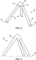
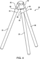
- Figs. 2 and 3 show another embodiment of a safety device 40, wherein a solid frame 42 includes two sockets 44.
- the sockets 44 are angled with respect to each other, to provide the desired angle between the glow sticks 25.
- a glow stick 25 is joined into each socket 44 to create two legs of a tripod, wherein the frame 42 includes the third leg 46.
- the tripod safety device 40 may then be placed on a generally flat surface 45, with the free ends of glow sticks 25 and leg 46 downward on the surface 45, for visibly warning others of the situation.
- the third leg 46 is desirably integral with the remainder of the frame 42, but can also be separate and attachable.
- three glow sticks may form the three legs of the tripodic, pyramidal safety device, resulting in more visibility and a more compact device for storage following use.
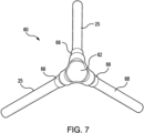
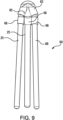
- Figs. 4-9 show hinged sockets allowing the user to move the safety device 60 between an expanded position shown in Figs. 4-8 and a collapsed storage position of Fig. 9 .
- the safety device 60 includes a frame 62 with three socket extensions 66 each including a socket opening 64 for receiving (e.g., by a friction fit) an end of a glow stick 25, other illumination rod, or a non-illuminating matching leg 68.
- Each socket extension 66 is secured to the remaining top portion of frame 62 by a hinge 65, allowing the socket extensions 66 to move between the storage and use positions.
- the sockets 64 are preferably equidistant about the bottom periphery of the frame 62, and extending or extendable at the same angle outward from a frame centerline, but variations in angles and position can be used, depending on need.
- the non-illuminating leg 68 allows for a partial triangle to be formed by the two glow sticks 25, thereby better matching the traditional caution triangle.
- Fig. 10 shows a safety device 70 similar to Figs. 4-8 , but without hinged sockets, and disassembled for storage, before use.
- the frame 72 and the unconnected glow sticks 25 are stored in a carrying bag or other container 80.
- each glow stick 25 (or non-illuminating leg 78) has two identical ends, where either end can be press-fit by the user into a correspondingly sized and shaped socket 74.
- each glow stick or leg has a connector (e.g., threads) at a first end that fits within the corresponding frame socket.
- the safety device, frame, and/or glow sticks described herein are available for the safety device, frame, and/or glow sticks described herein.
- the length, width, color, and/or end connection of the glow sticks can vary, depending on need.
- the number and orientation of the glow sticks can vary, such as described above.
- the tripodic safety devices shown in Figs. 2-8 can alternatively include one or two foldable, hinged connections between the sockets for the glow sticks, such that, for example, the non-illuminating leg does not fold.
- the safety device provides improved visibility during use, particularly in low light situations.
Landscapes
- Engineering & Computer Science (AREA)
- Physics & Mathematics (AREA)
- General Physics & Mathematics (AREA)
- Theoretical Computer Science (AREA)
- Mechanical Engineering (AREA)
- Road Signs Or Road Markings (AREA)
Abstract
Description
- The invention relates to a safety triangle for use in automotive and other applications where improved visibility creates a safer environment.
- High visibility safety devices for automotive, construction and similar applications may include reflective triangles, flares, flashlights, strobes and similar devices. Such devices are often limited in their effectiveness by size, visibility, lack of fresh batteries, and other limitations.
- A need therefore exists for a highly visible yet compact visible safety device, preferably one that does not use batteries yet remains available for use on short notice.
- A high visibility safety device is provided, such as can be stored in a vehicle and displayed to indicate caution or emergencies. The safety device of embodiments includes one or more illumination rods. The one or more illumination rods form an illuminated beacon, such as a safety triangle. A single illumination rod can be used, but preferably two or three illumination rods are used to form a partial or full triangle or a pyramidal shape.
- The illumination rods can be battery powered LED or other light bars, but are preferably each a self-contained, short-term light-source such as a glow stick. Suitable glow sticks, also known as light sticks, chem lights, light wands, or light rods, are generally formed of a translucent plastic tube containing isolated substances that, when combined, make light through chemiluminescence.
- In embodiments, the safety device includes a frame having one or more sockets each compatible with a first end of an illumination rod, such that when one or more illumination rod are engaged with the one or more sockets, a standable illuminated frame is enabled. The illumination rods can be vertical extensions from the frame, with free ends facing upwards from a frame base, or downwards as legs for a tripodic, or pyramidal device. A horizonal rod can be used to complete a three-sided illuminated triangle.
- A safety triangle as disclosed preferably includes a small and/or foldable frame having a plurality of sockets that assemble with standard size glow sticks of the kind that use a reactive fluorescing composition that glows once the glow stick is partially bent and/or otherwise activated.
- In embodiments, the safety device includes at least two sockets, each compatible with one end of an illumination rod. A second end of at least two of the illumination rods is a free end configured to extend upward or set upon a surface. In other embodiments, there are three, four, or more sockets, each for one end of an illumination rod. The illumination rod can be held in the socket by friction, threads, or any other suitable means.
- In embodiments, the safety device includes a tripodic frame including the one or more sockets and any other leg(s) extending at an angle to each other. The device can include three legs in an assembled configuration, with one, two or all three of the legs being an illumination rod. In embodiments, the device includes non-illumination legs or extensions, either fixed or attachable to the socket frame.
- The frame can include one or more foldable hinges, such as between socket pairs or one for each moveable socket, for folding the device and reducing a storage footprint. The hinge may be particularly useful for non-illuminating frame legs, or for storing a preassembled safety device. In other embodiments, the socket frame and the illumination rods are stored unconnected in a storage container. Extra illumination rods can be included for future uses before replenishment is possible.
- Embodiments further include a use of a glow stick for a high visibility safety device, such as according to any of the claims or described embodiments. Embodiments also include a high visibility safety device kit including the frame and a plurality of attachable glow sticks or other illumination rods as discussed and claimed herein.
- Embodiments further include methods of using a high visibility safety device as discussed and claimed herein. The methods may include steps of: inserting a first end of one or more glow sticks or other illumination rods into one or more sockets of a frame to form a standable illuminated frame; and setting the standable illuminated frame on a surface near an area of safety concern. The frame can be set on the surface on a second, free end, which is opposite the first end, of each illumination rod extending upwards, or the second, free end of each of the one or more illumination rods setting on the surface as support legs. When the safety device is no longer needed, the method includes removing the one or more illumination rods from the frame, such as for storage and/or disposal.
- The above-mentioned and other features and objects of this invention will be better understood from the following detailed description taken in conjunction with the drawings.
-
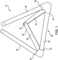
Fig. 1 is a perspective front view of a safety triangle in a fully assembled condition, according to one embodiment. -
Fig. 2 is a perspective front view of a safety triangle in a fully assembled condition, according to another embodiment. -
Fig. 3 is a side perspective view of the safety triangle shown inFig. 2 . -
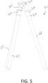
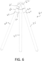
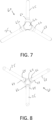
Figs. 4-8 shows different views of a safety triangle in a expanded use configuration, according to another embodiment. -
Fig. 9 shows a safety triangle ofFigs. 4-8 folded into a storge position. -
Fig. 10 shows a safety device disassembled in a storage container, according to another embodiment. - The figures show various embodiments of a high visibility safety device, generally referred to as a safety triangle. The safety device preferably includes a base frame having one or more sockets that are each compatible with one end of a glow stick such that when one or more glow sticks are engaged with the one or more sockets, a standable illuminated frame is enabled.
-
Fig. 1 shows one embodiment of asafety device 10 having afoldable frame 20 and a set of sockets. Two upwardly extendingsockets 22 are each engaged with aseparate glow stick 25 to create two sides of an upward extending triangle. Athird glow stick 25 is then joined between two facingsockets 24 to create a hypotenuse of the triangle. The frame includes twoside legs hinge 34. Each ofside legs socket 22 and onesocket 24, disposed at the suitable angle to each other to form the desired triangle. As a result, onehorizontal glow stick 25 that is generally coplanar with the twofoldable side legs frame 20 combine to create alower end 28 upon which thesafety device 10 may rest on a generally flat surface. Following use, theglow sticks 25 may be discarded and theframe 20 may be folded into a compact stowable form for later use. -
Figs. 2 and 3 show another embodiment of asafety device 40, wherein asolid frame 42 includes twosockets 44. Thesockets 44 are angled with respect to each other, to provide the desired angle between theglow sticks 25. Aglow stick 25 is joined into eachsocket 44 to create two legs of a tripod, wherein theframe 42 includes thethird leg 46. Thetripod safety device 40 may then be placed on a generallyflat surface 45, with the free ends ofglow sticks 25 andleg 46 downward on thesurface 45, for visibly warning others of the situation. Thethird leg 46 is desirably integral with the remainder of theframe 42, but can also be separate and attachable. - Alternatively to the embodiment shown in
Figs. 2 and 3 , three glow sticks may form the three legs of the tripodic, pyramidal safety device, resulting in more visibility and a more compact device for storage following use. -
Figs. 4-9 show hinged sockets allowing the user to move thesafety device 60 between an expanded position shown inFigs. 4-8 and a collapsed storage position ofFig. 9 . InFigs. 4-9 , thesafety device 60 includes aframe 62 with threesocket extensions 66 each including a socket opening 64 for receiving (e.g., by a friction fit) an end of aglow stick 25, other illumination rod, or anon-illuminating matching leg 68. Eachsocket extension 66 is secured to the remaining top portion offrame 62 by ahinge 65, allowing thesocket extensions 66 to move between the storage and use positions. Thesockets 64 are preferably equidistant about the bottom periphery of theframe 62, and extending or extendable at the same angle outward from a frame centerline, but variations in angles and position can be used, depending on need. Thenon-illuminating leg 68 allows for a partial triangle to be formed by the twoglow sticks 25, thereby better matching the traditional caution triangle. -
Fig. 10 shows asafety device 70 similar toFigs. 4-8 , but without hinged sockets, and disassembled for storage, before use. Theframe 72 and theunconnected glow sticks 25 are stored in a carrying bag orother container 80. In this embodiment, it is shown that each glow stick 25 (or non-illuminating leg 78) has two identical ends, where either end can be press-fit by the user into a correspondingly sized and shapedsocket 74. In an alternative embodiment each glow stick or leg has a connector (e.g., threads) at a first end that fits within the corresponding frame socket. - Various sizes, shapes, and configurations are available for the safety device, frame, and/or glow sticks described herein. For example, the length, width, color, and/or end connection of the glow sticks can vary, depending on need. The number and orientation of the glow sticks can vary, such as described above. The tripodic safety devices shown in
Figs. 2-8 can alternatively include one or two foldable, hinged connections between the sockets for the glow sticks, such that, for example, the non-illuminating leg does not fold. - Thus an easily storable and reusable safety device is provided. The safety device provides improved visibility during use, particularly in low light situations.
- While in the foregoing specification this invention has been described in relation to certain preferred embodiments thereof, and many details have been set forth for purpose of illustration, it will be apparent to those skilled in the art that the device and placard are susceptible to additional embodiments and that certain of the details described herein can be varied considerably without departing from the basic principles of the invention.
Claims (14)
a frame, the frame having one or more sockets that are each compatible with a first end of an illumination rod such that when one or more illumination rod are engaged with the one or more sockets, a standable illuminated frame is enabled.
Applications Claiming Priority (1)
| Application Number | Priority Date | Filing Date | Title |
|---|---|---|---|
| US202163225043P | 2021-07-23 | 2021-07-23 |
Publications (1)
| Publication Number | Publication Date |
|---|---|
| EP4141853A1 true EP4141853A1 (en) | 2023-03-01 |
Family
ID=82608460
Family Applications (1)
| Application Number | Title | Priority Date | Filing Date |
|---|---|---|---|
| EP22185109.0A Withdrawn EP4141853A1 (en) | 2021-07-23 | 2022-07-15 | Safety triangle |
Country Status (1)
| Country | Link |
|---|---|
| EP (1) | EP4141853A1 (en) |
Citations (3)
| Publication number | Priority date | Publication date | Assignee | Title |
|---|---|---|---|---|
| KR20170081843A (en) * | 2016-01-05 | 2017-07-13 | 금오공과대학교 산학협력단 | emergency triangle |
| US10386046B2 (en) * | 2014-05-20 | 2019-08-20 | Stickbulb Llc | Modular lighting system where the lighting elements are structurally integral to the support of the fixtures |
| CN110936890A (en) * | 2019-12-09 | 2020-03-31 | 宏图智能物流股份有限公司 | Traffic accident warning triangle tablet is deployed in remote control |
-
2022
- 2022-07-15 EP EP22185109.0A patent/EP4141853A1/en not_active Withdrawn
Patent Citations (3)
| Publication number | Priority date | Publication date | Assignee | Title |
|---|---|---|---|---|
| US10386046B2 (en) * | 2014-05-20 | 2019-08-20 | Stickbulb Llc | Modular lighting system where the lighting elements are structurally integral to the support of the fixtures |
| KR20170081843A (en) * | 2016-01-05 | 2017-07-13 | 금오공과대학교 산학협력단 | emergency triangle |
| CN110936890A (en) * | 2019-12-09 | 2020-03-31 | 宏图智能物流股份有限公司 | Traffic accident warning triangle tablet is deployed in remote control |
Similar Documents
| Publication | Publication Date | Title |
|---|---|---|
| US7782223B2 (en) | Flashing flare warning device | |
| US6265969B1 (en) | Telescoping warning device for motor vehicle | |
| AU2010246335B2 (en) | Collapsible light | |
| US5122781A (en) | Hazard warning light | |
| US4055840A (en) | Reusable safety warning device | |
| US6523778B2 (en) | Illuminated emergency signaling device and flying balloon | |
| US4989123A (en) | Collapsible light shade for a portable light | |
| US4145731A (en) | Simulated extendable and collapsible evergreen tree | |
| US5155667A (en) | Telescoping warning lamp device | |
| US5381325A (en) | Self-positioning lamp fixture with stabilizing base | |
| US3876970A (en) | Compact, battery-powered light | |
| US6729932B2 (en) | Toy with illuminated polyhedron | |
| KR101282241B1 (en) | Traffic safety signboard for portable | |
| US6769793B2 (en) | Expandable decoration | |
| JPS5923281Y2 (en) | fluorescent lantern | |
| US5613764A (en) | Internally illuminated decorative objects | |
| US20190225148A1 (en) | Foldable warning triangle assembly | |
| US20180187869A1 (en) | Lantern system and method | |
| US12018813B1 (en) | Lamp shade assembly and associated method for using the same | |
| JPH0588369U (en) | Mannequin construction, especially for clothing | |
| US3593016A (en) | Car battery operated camp and trouble light | |
| US20010009515A1 (en) | Scissors worklight | |
| CN221665888U (en) | An outdoor flashlight | |
| EP0656445A1 (en) | Foldable and transportable beacon for traffic signalling for emergency use on public roadways and other uses | |
| KR101531042B1 (en) | Lantern |
Legal Events
| Date | Code | Title | Description |
|---|---|---|---|
| PUAI | Public reference made under article 153(3) epc to a published international application that has entered the european phase |
Free format text: ORIGINAL CODE: 0009012 |
|
| STAA | Information on the status of an ep patent application or granted ep patent |
Free format text: STATUS: THE APPLICATION HAS BEEN PUBLISHED |
|
| AK | Designated contracting states |
Kind code of ref document: A1 Designated state(s): AL AT BE BG CH CY CZ DE DK EE ES FI FR GB GR HR HU IE IS IT LI LT LU LV MC MK MT NL NO PL PT RO RS SE SI SK SM TR |
|
| STAA | Information on the status of an ep patent application or granted ep patent |
Free format text: STATUS: REQUEST FOR EXAMINATION WAS MADE |
|
| 17P | Request for examination filed |
Effective date: 20230718 |
|
| RBV | Designated contracting states (corrected) |
Designated state(s): AL AT BE BG CH CY CZ DE DK EE ES FI FR GB GR HR HU IE IS IT LI LT LU LV MC MK MT NL NO PL PT RO RS SE SI SK SM TR |
|
| STAA | Information on the status of an ep patent application or granted ep patent |
Free format text: STATUS: THE APPLICATION IS DEEMED TO BE WITHDRAWN |
|
| 18D | Application deemed to be withdrawn |
Effective date: 20250201 |