EP4141779A1 - Management information display system and management information display method - Google Patents
Management information display system and management information display method Download PDFInfo
- Publication number
- EP4141779A1 EP4141779A1 EP21813468.2A EP21813468A EP4141779A1 EP 4141779 A1 EP4141779 A1 EP 4141779A1 EP 21813468 A EP21813468 A EP 21813468A EP 4141779 A1 EP4141779 A1 EP 4141779A1
- Authority
- EP
- European Patent Office
- Prior art keywords
- taken out
- information
- person
- detecting unit
- placement
- Prior art date
- Legal status (The legal status is an assumption and is not a legal conclusion. Google has not performed a legal analysis and makes no representation as to the accuracy of the status listed.)
- Granted
Links
Images



Classifications
-
- G—PHYSICS
- G06—COMPUTING OR CALCULATING; COUNTING
- G06F—ELECTRIC DIGITAL DATA PROCESSING
- G06F3/00—Input arrangements for transferring data to be processed into a form capable of being handled by the computer; Output arrangements for transferring data from processing unit to output unit, e.g. interface arrangements
- G06F3/01—Input arrangements or combined input and output arrangements for interaction between user and computer
- G06F3/048—Interaction techniques based on graphical user interfaces [GUI]
-
- H—ELECTRICITY
- H04—ELECTRIC COMMUNICATION TECHNIQUE
- H04N—PICTORIAL COMMUNICATION, e.g. TELEVISION
- H04N9/00—Details of colour television systems
- H04N9/12—Picture reproducers
- H04N9/31—Projection devices for colour picture display, e.g. using electronic spatial light modulators [ESLM]
- H04N9/3179—Video signal processing therefor
-
- G—PHYSICS
- G06—COMPUTING OR CALCULATING; COUNTING
- G06Q—INFORMATION AND COMMUNICATION TECHNOLOGY [ICT] SPECIALLY ADAPTED FOR ADMINISTRATIVE, COMMERCIAL, FINANCIAL, MANAGERIAL OR SUPERVISORY PURPOSES; SYSTEMS OR METHODS SPECIALLY ADAPTED FOR ADMINISTRATIVE, COMMERCIAL, FINANCIAL, MANAGERIAL OR SUPERVISORY PURPOSES, NOT OTHERWISE PROVIDED FOR
- G06Q10/00—Administration; Management
- G06Q10/08—Logistics, e.g. warehousing, loading or distribution; Inventory or stock management
-
- G—PHYSICS
- G06—COMPUTING OR CALCULATING; COUNTING
- G06Q—INFORMATION AND COMMUNICATION TECHNOLOGY [ICT] SPECIALLY ADAPTED FOR ADMINISTRATIVE, COMMERCIAL, FINANCIAL, MANAGERIAL OR SUPERVISORY PURPOSES; SYSTEMS OR METHODS SPECIALLY ADAPTED FOR ADMINISTRATIVE, COMMERCIAL, FINANCIAL, MANAGERIAL OR SUPERVISORY PURPOSES, NOT OTHERWISE PROVIDED FOR
- G06Q10/00—Administration; Management
- G06Q10/08—Logistics, e.g. warehousing, loading or distribution; Inventory or stock management
- G06Q10/087—Inventory or stock management, e.g. order filling, procurement or balancing against orders
-
- G—PHYSICS
- G06—COMPUTING OR CALCULATING; COUNTING
- G06Q—INFORMATION AND COMMUNICATION TECHNOLOGY [ICT] SPECIALLY ADAPTED FOR ADMINISTRATIVE, COMMERCIAL, FINANCIAL, MANAGERIAL OR SUPERVISORY PURPOSES; SYSTEMS OR METHODS SPECIALLY ADAPTED FOR ADMINISTRATIVE, COMMERCIAL, FINANCIAL, MANAGERIAL OR SUPERVISORY PURPOSES, NOT OTHERWISE PROVIDED FOR
- G06Q50/00—Information and communication technology [ICT] specially adapted for implementation of business processes of specific business sectors, e.g. utilities or tourism
- G06Q50/10—Services
-
- H—ELECTRICITY
- H04—ELECTRIC COMMUNICATION TECHNIQUE
- H04N—PICTORIAL COMMUNICATION, e.g. TELEVISION
- H04N5/00—Details of television systems
- H04N5/74—Projection arrangements for image reproduction, e.g. using eidophor
-
- H—ELECTRICITY
- H04—ELECTRIC COMMUNICATION TECHNIQUE
- H04N—PICTORIAL COMMUNICATION, e.g. TELEVISION
- H04N9/00—Details of colour television systems
- H04N9/12—Picture reproducers
- H04N9/31—Projection devices for colour picture display, e.g. using electronic spatial light modulators [ESLM]
- H04N9/3191—Testing thereof
- H04N9/3194—Testing thereof including sensor feedback
-
- G—PHYSICS
- G03—PHOTOGRAPHY; CINEMATOGRAPHY; ANALOGOUS TECHNIQUES USING WAVES OTHER THAN OPTICAL WAVES; ELECTROGRAPHY; HOLOGRAPHY
- G03B—APPARATUS OR ARRANGEMENTS FOR TAKING PHOTOGRAPHS OR FOR PROJECTING OR VIEWING THEM; APPARATUS OR ARRANGEMENTS EMPLOYING ANALOGOUS TECHNIQUES USING WAVES OTHER THAN OPTICAL WAVES; ACCESSORIES THEREFOR
- G03B29/00—Combinations of cameras, projectors or photographic printing apparatus with non-photographic non-optical apparatus, e.g. clocks or weapons; Cameras having the shape of other objects
Definitions
- the present disclosure relates to a management information display system and a management information display method.
- Storage states of objects such as tools, that are placed on predetermined storage locations, such as shelves and stands, may be managed, the storage states indicating, for example, whether or not the objects have been taken out and by whom the objects have been taken out.
- a known technique for such management enables storage states of objects to be known readily by, for example, storing the storage state in a storage and displaying the storage state on a display as needed (see, for example, Patent Literature 1).
- Patent Literature 1 Japanese Patent Application Publication No. 2009-070259
- the display is arranged at a position different from the positions where the objects are placed. Therefore, it is difficult for an operator returning one of the objects, to know information on a specific position to place the object instantly, for example.
- the present disclosure is made in view of the above, and an object thereof is to provide a management information display system and a management information display method that enable management states of objects to be readily known.
- a management information display system comprising: a management state detecting unit configured to detect a placement state of an object placed on a predetermined placement area such that the object is able to be taken out; a projecting device configured to be capable of projecting a projection image onto the predetermined placement area; and a control device configured to: determine, based on a detection result from the management state detecting unit, whether or not the object has been taken out from the predetermined placement area; set projection information including information on the object that has been taken out, when the control device determines that the object has been taken out; and control the projecting device such that the projection image representing the projection information is projected onto a position where the object had been placed on the predetermined placement area.
- a management information display method including: detecting a placement state of an object placed on a predetermined placement area such that the object is able to be taken out; determining, based on a result of the detecting of the placement state, whether or not the object has been taken out from the predetermined placement area; setting projection information including information on the object that has been taken out when it is determined that the object has been taken out; and projecting, by means of a projecting device, a projection image representing the projection information onto a position where the object had been placed on the predetermined placement area.
- the present disclosure provides a management information display system and a management information display method that enable management states of objects to be readily known.
- Embodiments of a management information display system and a management information display method according to the present disclose will hereinafter be described based on the drawings.
- the invention is not limited by these embodiments.
- elements in the following embodiments include those easily substitutable by persons skilled in the art or those that are substantially the same.
- FIG. 1 is a diagram schematically illustrating an example of a management information display system 100 according to an embodiment.
- the management information display system 100 includes a management state detecting unit 10, a projecting device 20, and a control device 30.
- the management information display system 100 detects a management state of an object T placed in a room, such as a storeroom, for example, and displays projection information according to the management state.
- the object T is placed on a placement surface (placement area) 40a of a placement stand 40, for example, in a state where the object T is able to be taken out.
- this object T include a tool to be used in an operation and an exhibit to be exhibited at an exhibition.
- the object T is not limited to these examples, and the object T may be any other type of an article that is placed on a predetermined placement area such that the object T is able to be picked up from the predetermined placement area.
- Tools T1 and T2 of different kinds will be described as examples of the object T with respect to the embodiment.
- FIG. 1 illustrates the tool T1 in a cylindrical shape and the tool T2 in a triangular prism shape.
- the tools are not limited to these shapes, and they may have any other shapes.
- the tools T1 and T2 may be shaped identically to each other.
- One or more placement stands 40 are provided in the storeroom, for example. With respect to this embodiment, a case in which one object T is placed on a single placement stand 40 will be described as an example. However, a case is not limited to this example, and plural objects T may be placed on a single placement stand.
- the placement surface 40a may be, for example, planar, but not limited to this example, and the placement surface 40a may be a non-flat surface, such as an area provided with projections and depressions.
- the management state detecting unit 10 detects a management state of the object T.
- the management state detecting unit 10 has an object detecting unit 11, an RFID detecting unit 12, and a person detecting unit 13.
- One object detecting unit 11, one RFID detecting unit 12, and one person detecting unit 13 may be provided for a detection of one placement stand 40 or one object T, for example, or one or more may be provided for a detection of the objects in the whole storeroom.
- the object detecting unit 11 detects a placement state of the object T on the placement surface 40a. Any of various sensors, such as a three-dimensional measurement sensor like an RGB-D camera, and an optical sensor, may be used as the object detecting unit 11, for example.
- the object detecting unit 11 is able to detect, as a placement state, a shape of the object T and a position and a posture of the object T on the placement surface 40a, for example.
- the object detecting unit 11 detects the placement surface 40a in a state in which the object T is not placed thereon.
- the object detecting unit 11 detects, as a placement state, the state in which the object T is not placed on the placement surface 40a.
- the object detecting unit 11 transmits the placement state information I1 that is a detection result to the control device 30.
- the RFID (radio frequency identifier) detecting unit 12 reads a predetermined RF tag 14 and obtains information that has been embedded in the RF tag 14.
- the RFID detecting unit 12 is capable of reading the RF tag 14 positioned within a predetermined distance from the RFID detecting unit 12, for example. This predetermined distance may be set as appropriate.
- the RFID detecting unit 12 is provided for each placement stand 40, for example.
- the RFID detecting unit 12 may be provided at another location, such as a doorway of the storeroom, for example.
- An RFID reader is used, for example, as the RFID detecting unit 12.
- the RF tag 14 is owned by a person, such as an operator P, who has been permitted to come in and out of the storeroom, for example.
- the RFID detecting unit 12 obtains the identification information of the operator P by reading the RF tag 14.
- the RFID detecting unit 12 transmits obtained identification information I2 to the control device 30.
- the person detecting unit 13 detects a person in the room, such as the storeroom.
- a device that may be used as the person detecting unit 13, for example, is capable of obtaining information on a person to enable an appearance of the person to be identified, the appearance being, for example, the face and figure of the person.
- this device include an imaging device, such as a camera, and a three-dimensional measurement sensor, such as an RGB-D camera.
- the appearance of the person and the identification information are stored in a storage (a storage 35 of the control device 30 or an external storage) in association with each other, and a person is able to be identified by comparison between a detection result and the stored appearance through image processing, for example.
- the identification of the person may be performed by the control device 30.
- the person detecting unit 13 transmits obtained person information I3 to the control device 30.
- the projecting device 20 is provided on a wall or a ceiling of the storeroom.
- the projecting device 20 is able to project a projection image onto the placement surface 40a of the placement stand 40.
- the projecting device 20 is able to project the projection image.
- the control device 30 Based on a detection result from the management state detecting unit 10, the control device 30 sets projection information according to a management state.
- the control device 30 controls the projecting device 20 such that the projection image indicating a set projection information is projected onto the placement surface 40a.
- the control device 30 has a management state acquiring unit 31, a determining unit 32, a person identifying unit 33, a display controller 34, and the storage 35.
- the management state acquiring unit 31 obtains the detection result transmitted from the management state detecting unit 10.
- the management state acquiring unit 31 obtains the placement state information I1 on the object T detected by the object detecting unit 11.
- the management state acquiring unit 31 obtains the identification information I2 on the person detected by the RFID detecting unit 12.
- the management state acquiring unit 31 obtains the person information I3 obtained by the person detecting unit 13.
- the determining unit 32 determines whether or not the object T has been taken out.
- the placement state information I1 indicates the shape of the object T and the position and the posture of the object T on the placement surface 40a, for example, the determining unit 32 is able to determine that the object T has not been taken out.
- the placement state information I1 indicates a state in which the object T is not placed on the placement surface 40a
- the determining unit 32 is able to determine that the object T has been taken out.
- the person identifying unit 33 described later identifies an object person who has taken out the object T.
- the determining unit 32 makes a determination for each of the plural objects T.
- the determining unit 32 determines whether or not the object person who has taken out the object T is present around the placement stand 40. First, based on a detection result from the RFID detecting unit 12 or the person detecting unit 13, the determining unit 32 determines whether or not a person is present around the placement stand 40. When a person is detected within a range of a predetermined distance or less from the placement stand 40, for example, the determining unit 32 is able to determine that a person is present around the placement stand 40. Next, based on an identification result from the person identifying unit 33 described later, the determining unit 32 determines whether or not the person detected around the placement stand 40 is the object person. When the person identified by the person identifying unit 33 is the object person, the determining unit 32 is able to determine that the object person who has taken out the object T is present around the placement stand 40.
- the determining unit 32 determines, based on a detection result from the object detecting unit 11, whether or not the object T has been returned onto the placement surface 40a.
- the placement state information I1 has been changed from a state indicating the placement surface 40a in which the object T is not placed thereon to a state including the shape of the object T and the position and the posture of the object T on the placement surface 40a
- the determining unit 32 determines that the object T has been returned. Furthermore, when the placement state information I1 indicates that the placement surface 40a is still in a state in which the object T is not placed thereon, the determining unit 32 determines that the object T has not been returned.
- the person identifying unit 33 identifies, based on the detection result from the RFID detecting unit 12 or the person detecting unit 13, the person who has taken out the object T as the object person.
- the person identifying unit 33 stores, into the storage 35, information on the object person and information on the object T taken out in association with each other.
- the person identifying unit 33 identifies, based on the detection result from the RFID detecting unit 12 or the person detecting unit 13, the person present around the placement stand 40.
- the person identifying unit 33 is able to identify an object person based on the identification information transmitted from the RFID detecting unit 12.
- the appearance of the person and the identification information are stored in association with each other in the storage 35 in advance, for example.
- the determining unit 32 is able to identify an object person.
- the display controller 34 sets projection information including information on the object T that has been taken out.
- the projection information includes, for example, the information on the object T taken out, and information indicating that an object person has taken out the object T.
- the information on the object T may include, for example, at least one of: textual information indicating a name of the object T; and image information indicating an appearance of the object T.
- the display controller 34 sets projection information for each of the objects T.
- the display controller 34 may set the projection information so that a moving image is displayed.
- the display controller 34 controls the projecting device 20 such that a projection image representing the set projection information is projected onto the placement surface 40a.
- the display controller 34 transmits a signal including, for example, the projection information and specification information specifying a projection range on the placement surface 40a, to the projecting device 20.
- the projecting device 20 projects, based on the projection information and the specification information, the projection image onto the placement surface 40a.
- the specification information may correspond to, for example, a range including a position on the placement surface 40a, the position being where the object T had been placed.
- the display controller 34 controls the projecting device 20 to cause the projection image to be highlight-displayed. That is, the display controller 34 controls the projecting device 20 such that the projection image projected onto the placement surface 40a where the object T taken out by the object person is to be placed is highlight-displayed. By this highlight-display, where to return the object T is able to be clearly notified to the object person.
- the display controller 34 controls the projecting device 20 such that the plural projection images corresponding to the objects T taken out by the object person are highlight-displayed.
- the display controller 34 controls the projecting device 20 such that any projection image corresponding to an object T taken out by a person different from the object person is not highlight-displayed.
- the display controller 34 controls the projecting device 20 to cause the projection image to be erased. That is, the display controller 34 controls the projecting device 20 such that the projection image projected on the placement surface 40a is erased.
- the storage 35 stores various kinds of information.
- the storage 35 has a management information storage 36 and an object information storage 37.
- the management information storage 36 stores information (hereinafter, referred to as management information) indicating a management state of an object T on each placement stand 40.
- Examples of the management information include, for example, identification information of each placement stand 40, various types of information on an object T placed on each placement stand 40, and information on whether or not the objects T have been taken out.
- Examples of the various types of information on the objects T include names and appearances of the objects T, information for identification of the objects T, maintenance frequencies of the objects T, and an increase or decrease in the number of objects T.
- the identification information of the object T may be stored in association with the identification information of the placement stand 40 where the object T is placed.
- the object information storage 37 stores information on whether or not an object T has been taken out, and information on an object person who has taken out the object T when the object T has been taken out in association with each other.
- Information on the object T and information on the placement stand 40 in the management information storage 36 may be stored in association with information on the object T and information on the object person in the object information storage 37.
- FIG. 2 to FIG. 8 are diagrams schematically illustrating an example of the operation of the management information display system 100 according to the embodiment.
- the tool T1 has been placed on the placement surface 40a of the placement stand 40.
- the object detecting unit 11 detects a shape of the tool T1, and a placement state, such as a position and a posture, of the tool T1 on the placement surface 40a. Furthermore, the object detecting unit 11 detects a placement state similarly for any other object T, such as the tool T2 illustrated in FIG. 1 . An example will hereinafter be described with respect to the tool T1 but similar description can be made for any other object T.
- the object detecting unit 11 transmits placement state information I1 that has been detected to the control device 30.
- the control device 30 obtains, at the management state acquiring unit 31, the placement state information 11.
- the placement state included in the placement state information I1 is a state in which the tool T1 is placed on the placement surface 40a, for example.
- the determining unit 32 thus determines that the object T has not been taken out.
- the operator P may access the placement stand 40.
- the RFID detecting unit 12 reads the RF tag 14 and obtains identification information of the operator P, the identification having been embedded in the RF tag 14.
- the RFID detecting unit 12 transmits, to the control device 30, identification information I2 obtained.
- the operator P may take out the tool T1.
- the placement surface 40a of the placement stand 40 is brought into a state in which the tool T1 is not placed thereon.
- the object detecting unit 11 detects the placement surface 40a in the state in which the tool T1 is not placed thereon.
- the object detecting unit 11 transmits, to the control device 30, placement state information I1 detected.
- the control device 30 obtains, at the management state acquiring unit 31, the placement state information 11.
- the placement state included in the placement state information I1 is a state in which the tool T1 is not placed on the placement surface 40a, for example.
- the determining unit 32 thus determines that the tool T1 has been taken out.
- the person identifying unit 33 identifies, based on the detection result from the RFID detecting unit 12 or the person detecting unit 13, the object person who has taken out the tool T1. Based on identification of the operator P included in the identification information I2 or image information on the operator P included in the person information 13, for example, the person identifying unit 33 is able to identify the operator P as the object person. After identifying the operator P as the object person, the person identifying unit 33 stores, into the object information storage 37 of the storage 35, information on the operator P who is the object person and information on the tool T1 taken out in association with each other.
- the display controller 34 Based on the determination result from the determining unit 32 and the identification result from the person identifying unit 33, the display controller 34 sets projection information.
- the display controller 34 sets the projection information such that the projection information includes, for example, information on the tool T1 taken out, and information indicating the operator P that is the object person who has taken out the tool T1.
- the display controller 34 controls the projecting device 20 such that a projection image representing the set projection information is projected onto the placement surface 40a.
- the display controller 34 transmits a signal including the projection information and specification information specifying a projection range on the placement surface 40a to the projecting device 20.
- the specification information may correspond to, for example, a range including a position on the placement surface 40a, the position being where the tool T1 had been placed.
- the display controller 34 sets projection information similarly for the another object T.
- the projecting device 20 receives the signal from the control device 30 and projects the projection image representing the projection information described above, over the projection range specified. As illustrated in FIG. 4 , a projection image D is thereby displayed over a range including a position Q where the tool T1 had been placed on the placement surface 40a in a state in which the tool T1 has been taken out.
- the projection image D includes, for example, an image D1 indicating a name of the tool T1 taken out, an image D2 depicting an appearance of the tool T1, and an image D3 indicating identification information of the operator P that is the object person who has taken out the tool T1.
- Projecting the projection image D onto the placement surface 40a corresponding to the tool T1 enables the operator P or an administrator to know that: the object T that has been taken out is the tool T1; a management location of the tool T1 is the placement surface 40a; and the object person who has taken out the tool T1 is the operator P, in association with one another.
- the image D2 depicting the appearance of the tool T1 may be projected onto a position corresponding to the position Q where the tool T1 had been placed, for example.
- the operator P is thereby able to know the position to return the tool T1 intuitively.
- the display controller 34 controls the projecting device 20 such that a projection image is projected similarly onto a placement surface 40a where the another object T had been placed.
- the determining unit 32 determines, based on the detection result from the RFID detecting unit 12 or the person detecting unit 13, whether or not the object person who has taken out the tool T1 is present around the placement stand 40. Firstly, the determining unit 32 determines whether or not any person is present around the placement stand 40. For example, when an RF tag 14 has been read by the RFID detecting unit 12 or when a person has been detected by the person detecting unit 13, the determining unit 32 is able to determine that a person is present around the placement stand 40. In the example illustrated in FIG. 5 , a person (the operator P) around the placement stand is detected by the person detecting unit 13 and a result of the detection is transmitted to the control device 30. Based on the detection result, the determining unit 32 is able to determine that a person (the operator P) is present around the placement stand 40.
- the person identifying unit 33 identifies the person around the placement stand 40.
- the person identifying unit 33 is able to identify the person based on the identification information embedded in the RF tag 14 of the person around the placement stand 40.
- the person identifying unit 33 is able to identify that the person is the operator P based on image information on the person included in the person information I3 and appearance information on the operator P stored in the storage 35 in advance.
- the determining unit 32 determines, based on the identification result from the person identifying unit 33, whether or not the person present around the placement stand 40 is the object person who has taken out the tool T1.
- the person identifying unit 33 has identified that the person present around the placement stand 40 is the operator P. Based on this identification result and information stored in the object information storage 37 of the storage 35, the determining unit 32 is able to determine that the person present around the placement stand 40 is the operator P.
- the display controller 34 controls the projecting device 20 such that the projection image D is highlight-displayed.
- a projection image Da that has been highlighted is projected onto the placement surface 40a, as illustrated in FIG. 6 .
- the projection image Da includes, for example, images D1a, D2a, and D3a obtaining from highlighting of the images D1, D2, and D3.
- the images D1a, D2a, and D3a depict, for example, the same content as the images D1, D2, and D3.
- the images D1a and D3a are highlight-displayed by their text being made bold.
- the image D2a is highlight-displayed by its outline being made bold.
- a specific mode of the highlight-displaying is not limited to those illustrated in FIG. 6 , and any other mode, such as a mode where an image is caused to blink, or a mode where an image is increased in brightness, may be adopted.
- the display controller 34 may control the projecting device 20 such that a projection image is also highlight-displayed, the projection image being on a placement surface 40a where the another object T had been placed.
- Highlight-displaying the projection image Da on the placement stand 40 corresponding to the tool T1 enables the operator P to readily know which placement stand 40 the tool T1 is to be returned to.
- the operator P returning the tool T1 to the placement stand 40 brings the placement surface 40a of the placement stand 40 into the state in which the tool T1 is placed on the placement surface 40a, as illustrated in FIG. 7 .
- the object detecting unit 11 detects the placement state in which the tool T1 is placed on the placement surface 40a.
- the object detecting unit 11 transmits, to the control device 30, placement state information I1 that has been detected.
- the control device 30 obtains, at the management state acquiring unit 31, the placement state information I1.
- the placement state included in the placement state information I1 is changed from a state in which the tool T1 is not placed on the placement surface 40a to a state in which the tool T1 is placed on the placement surface 40a.
- the determining unit 32 thus determines that the tool T1 has been returned.
- the display controller 34 controls the projecting device 20 to cause the projection image Da to be erased. That is, the display controller 34 controls the projecting device 20 such that the projection image Da projected on the placement surface 40a is erased. This control causes the projecting device 20 to stop projecting the projection image Da on the placement surface 40a. As a result, as illustrated in FIG. 8 , the projection image Da is no longer displayed on the placement surface 40a.
- the management state acquiring unit 31 stores, into the management information storage 36 of the storage 35, a position Qa where the tool T1 has newly been placed.
- FIG. 9 is a flowchart illustrating an example of a management information display method according to the embodiment.
- the management state detecting unit 10 detects various management states (Step S10).
- the determining unit 32 determines, based on the detection result from the management state detecting unit 10, whether or not the object T has been taken out (Step S20). When it is determined at Step S20 that the object T has not been taken out (No at Step S20), the processing of Step S20 is repeated.
- the person identifying unit 33 identifies the object person who has taken out the object T (Step S30).
- the display controller 34 sets the projection information (Step S40).
- the display controller 34 sets the projection information such that the projection information includes information on the object T taken out and information indicating that the object person has taken out the object T.
- the display controller 34 controls the projecting device 20 such that the projection image D representing the set projection information is projected onto the placement surface 40a. This control causes the projection image D to be projected onto the placement surface 40a (Step S50).
- the determining unit 32 determines, based on the detection result from the person detecting unit 13, whether or not the object person who has taken out the tool T1 is present around the placement stand 40 (Step S60). When it is determined at Step S60 that the object person who has taken out the tool T1 is not present around the placement stand 40 (No at Step S60), the processing of Step S60 is repeated. Furthermore, when it is determined that the object person who has taken out the tool T1 is present around the placement stand 40 (Yes at Step S60), the projecting device 20 is controlled such that the image projected onto the placement surface 40a where the tool T1 is to be placed is highlight-displayed. This control causes the projection image Da that has been highlighted to be displayed on the placement surface 40a (Step S70).
- the determining unit 32 determines whether or not the tool T1 has been returned (Step S80).
- Step S80 determines whether or not the tool T1 has been returned onto the placement surface 40a.
- the processing of Step S80 is repeated.
- the projecting device 20 is controlled such that the position where the tool T1 has been returned to is regarded as a new regular position and the image projected on the placement surface 40a is erased. This controls causes the projecting device 20 to stop the projection onto the placement surface 40a (Step S90).
- the management information display system 100 includes: the management state detecting unit 10 configured to detect the placement state of the object T placed on the predetermined placement surface 40a such that the object T is able to be taken out; the projecting device 20 configured to be capable of projecting a projection image onto the placement surface 40a; and the control device 30 configured to determine, based on the detection result from the management state detecting unit 10, whether or not the object T has been taken out from the placement surface 40a; to set projection information including information on the object T that has been taken out when the control device 30 determines that the object T has been taken out; and to control the projecting device 20 such that the projection image D representing the projection information is projected onto the position where the object T had been placed on the placement surface 40a.
- the management information display method includes: detecting the placement state of the object T placed on the predetermined placement surface 40a such that the object T is able to be taken out; determining, based on the result of the detecting of the placement state, whether or not the object T has been taken out from the placement surface 40a; setting the projection information including information on the object T that has been taken out when it is determined that the object T has been taken out; and projecting, by means of the projecting device 20, the projection image D representing the projection information onto the position where the object T had been placed on the placement surface 40a.
- the projection image D representing the information on the object T that has been taken out is projected onto the placement surface 40a when the object T has been taken out from the placement surface 40a. Therefore, an administrator who sees the placement surface 40a having the projection image D projected thereon is able to readily know the information related to the object T that had been placed on the placement surface 40a. The administrator is thereby able to readily know the management state of the object T which corresponds to the placement state of the object T.
- the management state detecting unit 10 is capable of detecting the information for identifying the object person who has taken out the object T, and the control device 30 identifies, based on the detection result from the management state detecting unit 10, the person who has taken out the object T as the object person, when it is determined that the object T has been taken out; and sets projection information such that the projection information includes information indicating that the object person has taken out the object T.
- This configuration enables an administrator to know the object T that has been taken out from the placement surface 40a and the object person who has taken out the object T in association with each other.
- the management state detecting unit 10 is capable of detecting information for identifying the object person who has taken out the object T and information for identifying the person present around the placement surface 40a, and the control device 30 identifies, based on the detection result from the management state detecting unit 10, the person who has taken out the object T as the object person, when it is determined that the object T has been taken out; determines, based on the detection result from the management state detecting unit 10, whether or not the object person is present around the placement surface 40a after the projection image D is projected onto the placement surface 40a; and controls the projecting device 20 such that projection information is highlight-displayed when it is determined that the object person is present around the placement surface 40a.
- This configuration enables the object person to readily know where to return the object T.
- the control device 30 determines, based on the detection result from the management state detecting unit 10, whether or not the object T has been returned to the placement surface 40a; and when the control device 30 determines that the object T has been returned, the control device 30 controls the projecting device 20 such that the projection of the projection image D is erased.
- This configuration enables the object person or the administrator to readily know that the object T has been returned since the projection of the projection image D is erased when the object T has been returned.
- the control device 30 sets the projection information such that the projection information includes image information representing the appearance of the object T when it is determined that the object T has been taken out. This configuration enables the object person or the administrator to readily know the appearance of the object T to be returned to the placement surface 40a.
- the management information display system 100 may have a configuration to transmit information to the operator P by output of sound.
- the management information display system 100 may be configured to be able to determine whether or not the operator P who is the object person that has taken out the object T is looking at the placement surface 40a of the placement stand 40 when the operator P is present around the placement stand 40 on which the object T had been placed.
- the management information display system 100 may be configured to output, by means of a sound output unit, for example, information to instruct the operator P to look at the placement surface 40a, when it is determined that the operator P is not looking at the placement surface 40a.
- the case in which the object T is placed on the placement surface 40a that is planar has been described as an example in the above described embodiment, but the embodiment is not limited to this example.
- a configuration in which the object T is placed in a three-dimensional placement portion or inside a container, such as a case, may be adopted.
- the projecting device 20 may project a projection image according to the shape of the placement portion for the object T.
- FIG. 10 is a diagram schematically illustrating another example of the operation of the management information display system 100.
- the display controller 34 may project the projection image D (the upper side in FIG.
- the display controller 34 may perform no projection of the projection image D (the lower side in FIG. 10 ). This configuration enables the object person to readily know where the object T is to be returned to since only the projection image D representing the information on the object T taken out by that object person is projected.
- a management information display system and a management information display method according to the present disclosure may be used in, for example, a processing apparatus, such as a computer.
Landscapes
- Engineering & Computer Science (AREA)
- Business, Economics & Management (AREA)
- Theoretical Computer Science (AREA)
- Economics (AREA)
- Physics & Mathematics (AREA)
- General Physics & Mathematics (AREA)
- Tourism & Hospitality (AREA)
- Human Resources & Organizations (AREA)
- Marketing (AREA)
- Strategic Management (AREA)
- General Business, Economics & Management (AREA)
- Signal Processing (AREA)
- Multimedia (AREA)
- General Engineering & Computer Science (AREA)
- Quality & Reliability (AREA)
- Operations Research (AREA)
- Development Economics (AREA)
- Entrepreneurship & Innovation (AREA)
- General Health & Medical Sciences (AREA)
- Primary Health Care (AREA)
- Health & Medical Sciences (AREA)
- Human Computer Interaction (AREA)
- Accounting & Taxation (AREA)
- Finance (AREA)
- Controls And Circuits For Display Device (AREA)
- User Interface Of Digital Computer (AREA)
- Management, Administration, Business Operations System, And Electronic Commerce (AREA)
- Projection Apparatus (AREA)
- Transforming Electric Information Into Light Information (AREA)
Abstract
Description
- The present disclosure relates to a management information display system and a management information display method.
- Storage states of objects, such as tools, that are placed on predetermined storage locations, such as shelves and stands, may be managed, the storage states indicating, for example, whether or not the objects have been taken out and by whom the objects have been taken out. A known technique for such management enables storage states of objects to be known readily by, for example, storing the storage state in a storage and displaying the storage state on a display as needed (see, for example, Patent Literature 1).
- Patent Literature 1:
Japanese Patent Application Publication No. 2009-070259 - According to the technique described in Patent Literature 1, the display is arranged at a position different from the positions where the objects are placed. Therefore, it is difficult for an operator returning one of the objects, to know information on a specific position to place the object instantly, for example.
- The present disclosure is made in view of the above, and an object thereof is to provide a management information display system and a management information display method that enable management states of objects to be readily known.
- According to one aspect, there is provided a management information display system, comprising: a management state detecting unit configured to detect a placement state of an object placed on a predetermined placement area such that the object is able to be taken out; a projecting device configured to be capable of projecting a projection image onto the predetermined placement area; and a control device configured to: determine, based on a detection result from the management state detecting unit, whether or not the object has been taken out from the predetermined placement area; set projection information including information on the object that has been taken out, when the control device determines that the object has been taken out; and control the projecting device such that the projection image representing the projection information is projected onto a position where the object had been placed on the predetermined placement area.
- According to one aspect, there is provided a management information display method, including: detecting a placement state of an object placed on a predetermined placement area such that the object is able to be taken out; determining, based on a result of the detecting of the placement state, whether or not the object has been taken out from the predetermined placement area; setting projection information including information on the object that has been taken out when it is determined that the object has been taken out; and projecting, by means of a projecting device, a projection image representing the projection information onto a position where the object had been placed on the predetermined placement area.
- The present disclosure provides a management information display system and a management information display method that enable management states of objects to be readily known.
-
-
FIG. 1 is a diagram schematically illustrating an example of a management information display system according to an embodiment; -
FIG. 2 is a diagram schematically illustrating an example of an operation of the management information display system according to the embodiment; -
FIG. 3 is a diagram schematically illustrating the example of the operation of the management information display system according to the embodiment; -
FIG. 4 is a diagram schematically illustrating the example of the operation of the management information display system according to the embodiment; -
FIG. 5 is a diagram schematically illustrating the example of the operation of the management information display system according to the embodiment; -
FIG. 6 is a diagram schematically illustrating the example of the operation of the management information display system according to the embodiment; -
FIG. 7 is a diagram schematically illustrating the example of the operation of the management information display system according to the embodiment; -
FIG. 8 is a diagram schematically illustrating the example of the operation of the management information display system according to the embodiment; -
FIG. 9 is a flowchart illustrating an example of a management information display method according to the embodiment; and -
FIG. 10 is a diagram schematically illustrating another example of the operation of the management information display system. - Embodiments of a management information display system and a management information display method according to the present disclose will hereinafter be described based on the drawings. The invention is not limited by these embodiments. Furthermore, elements in the following embodiments include those easily substitutable by persons skilled in the art or those that are substantially the same.
-
FIG. 1 is a diagram schematically illustrating an example of a management information display system 100 according to an embodiment. As illustrated inFIG. 1 , the management information display system 100 includes a managementstate detecting unit 10, aprojecting device 20, and acontrol device 30. The management information display system 100 detects a management state of an object T placed in a room, such as a storeroom, for example, and displays projection information according to the management state. - The object T is placed on a placement surface (placement area) 40a of a
placement stand 40, for example, in a state where the object T is able to be taken out. Examples of this object T include a tool to be used in an operation and an exhibit to be exhibited at an exhibition. However, the object T is not limited to these examples, and the object T may be any other type of an article that is placed on a predetermined placement area such that the object T is able to be picked up from the predetermined placement area. Tools T1 and T2 of different kinds will be described as examples of the object T with respect to the embodiment.FIG. 1 illustrates the tool T1 in a cylindrical shape and the tool T2 in a triangular prism shape. However, the tools are not limited to these shapes, and they may have any other shapes. Furthermore, the tools T1 and T2 may be shaped identically to each other. - One or more placement stands 40 are provided in the storeroom, for example. With respect to this embodiment, a case in which one object T is placed on a
single placement stand 40 will be described as an example. However, a case is not limited to this example, and plural objects T may be placed on a single placement stand. Theplacement surface 40a may be, for example, planar, but not limited to this example, and theplacement surface 40a may be a non-flat surface, such as an area provided with projections and depressions. - The management
state detecting unit 10 detects a management state of the object T. The managementstate detecting unit 10 has anobject detecting unit 11, anRFID detecting unit 12, and aperson detecting unit 13. Oneobject detecting unit 11, oneRFID detecting unit 12, and oneperson detecting unit 13 may be provided for a detection of one placement stand 40 or one object T, for example, or one or more may be provided for a detection of the objects in the whole storeroom. - The
object detecting unit 11 detects a placement state of the object T on theplacement surface 40a. Any of various sensors, such as a three-dimensional measurement sensor like an RGB-D camera, and an optical sensor, may be used as theobject detecting unit 11, for example. When the object T is on theplacement surface 40a of the placement stand 40, theobject detecting unit 11 is able to detect, as a placement state, a shape of the object T and a position and a posture of the object T on theplacement surface 40a, for example. Furthermore, when the object T is not on theplacement surface 40a, theobject detecting unit 11 detects theplacement surface 40a in a state in which the object T is not placed thereon. That is, in this case, theobject detecting unit 11 detects, as a placement state, the state in which the object T is not placed on theplacement surface 40a. Theobject detecting unit 11 transmits the placement state information I1 that is a detection result to thecontrol device 30. - The RFID (radio frequency identifier) detecting
unit 12 reads apredetermined RF tag 14 and obtains information that has been embedded in theRF tag 14. TheRFID detecting unit 12 is capable of reading theRF tag 14 positioned within a predetermined distance from theRFID detecting unit 12, for example. This predetermined distance may be set as appropriate. TheRFID detecting unit 12 is provided for each placement stand 40, for example. TheRFID detecting unit 12 may be provided at another location, such as a doorway of the storeroom, for example. An RFID reader is used, for example, as theRFID detecting unit 12. TheRF tag 14 is owned by a person, such as an operator P, who has been permitted to come in and out of the storeroom, for example. Identification information for identifying the operator P who is an owner thereof, for example, has been embedded in theRF tag 14. TheRFID detecting unit 12 obtains the identification information of the operator P by reading theRF tag 14. TheRFID detecting unit 12 transmits obtained identification information I2 to thecontrol device 30. - The
person detecting unit 13 detects a person in the room, such as the storeroom. A device that may be used as theperson detecting unit 13, for example, is capable of obtaining information on a person to enable an appearance of the person to be identified, the appearance being, for example, the face and figure of the person. Examples of this device include an imaging device, such as a camera, and a three-dimensional measurement sensor, such as an RGB-D camera. When such a device is used, the appearance of the person and the identification information are stored in a storage (astorage 35 of thecontrol device 30 or an external storage) in association with each other, and a person is able to be identified by comparison between a detection result and the stored appearance through image processing, for example. The identification of the person may be performed by thecontrol device 30. Theperson detecting unit 13 transmits obtained person information I3 to thecontrol device 30. - The projecting
device 20 is provided on a wall or a ceiling of the storeroom. The projectingdevice 20 is able to project a projection image onto theplacement surface 40a of theplacement stand 40. In this embodiment, based on control by thecontrol device 30 described later, the projectingdevice 20 is able to project the projection image. - Based on a detection result from the management
state detecting unit 10, thecontrol device 30 sets projection information according to a management state. Thecontrol device 30 controls the projectingdevice 20 such that the projection image indicating a set projection information is projected onto theplacement surface 40a. Thecontrol device 30 has a managementstate acquiring unit 31, a determiningunit 32, aperson identifying unit 33, adisplay controller 34, and thestorage 35. - The management
state acquiring unit 31 obtains the detection result transmitted from the managementstate detecting unit 10. The managementstate acquiring unit 31 obtains the placement state information I1 on the object T detected by theobject detecting unit 11. The managementstate acquiring unit 31 obtains the identification information I2 on the person detected by theRFID detecting unit 12. The managementstate acquiring unit 31 obtains the person information I3 obtained by theperson detecting unit 13. - Based on the detection result from the
object detecting unit 11, the determiningunit 32 determines whether or not the object T has been taken out. When the placement state information I1 indicates the shape of the object T and the position and the posture of the object T on theplacement surface 40a, for example, the determiningunit 32 is able to determine that the object T has not been taken out. Furthermore, when the placement state information I1 indicates a state in which the object T is not placed on theplacement surface 40a, the determiningunit 32 is able to determine that the object T has been taken out. When the determiningunit 32 determines that the object T has been taken out, theperson identifying unit 33 described later identifies an object person who has taken out the object T. When plural objects T are placed, the determiningunit 32 makes a determination for each of the plural objects T. - After the object person who has taken out the object T is identified and a projection image is projected onto the
placement surface 40a, the determiningunit 32 determines whether or not the object person who has taken out the object T is present around theplacement stand 40. First, based on a detection result from theRFID detecting unit 12 or theperson detecting unit 13, the determiningunit 32 determines whether or not a person is present around theplacement stand 40. When a person is detected within a range of a predetermined distance or less from theplacement stand 40, for example, the determiningunit 32 is able to determine that a person is present around theplacement stand 40. Next, based on an identification result from theperson identifying unit 33 described later, the determiningunit 32 determines whether or not the person detected around the placement stand 40 is the object person. When the person identified by theperson identifying unit 33 is the object person, the determiningunit 32 is able to determine that the object person who has taken out the object T is present around theplacement stand 40. - After the object T is taken out, the determining
unit 32 determines, based on a detection result from theobject detecting unit 11, whether or not the object T has been returned onto theplacement surface 40a. When the placement state information I1 has been changed from a state indicating theplacement surface 40a in which the object T is not placed thereon to a state including the shape of the object T and the position and the posture of the object T on theplacement surface 40a, the determiningunit 32 determines that the object T has been returned. Furthermore, when the placement state information I1 indicates that theplacement surface 40a is still in a state in which the object T is not placed thereon, the determiningunit 32 determines that the object T has not been returned. - When it is determined that the object T has been taken out, the
person identifying unit 33 identifies, based on the detection result from theRFID detecting unit 12 or theperson detecting unit 13, the person who has taken out the object T as the object person. When theperson identifying unit 33 has identified the object person, theperson identifying unit 33 stores, into thestorage 35, information on the object person and information on the object T taken out in association with each other. Furthermore, when the determiningunit 32 determines that a person is present around the placement stand 40 after a projection image is projected onto theplacement surface 40a, theperson identifying unit 33 identifies, based on the detection result from theRFID detecting unit 12 or theperson detecting unit 13, the person present around theplacement stand 40. - When the detection result from the
RFID detecting unit 12 is used, theperson identifying unit 33 is able to identify an object person based on the identification information transmitted from theRFID detecting unit 12. When the detection result from theperson detecting unit 13 is used, the appearance of the person and the identification information are stored in association with each other in thestorage 35 in advance, for example. By performing an image processing, for example, based on an image captured or a result measured and the appearance of the person stored in thestorage 35, the determiningunit 32 is able to identify an object person. - When the determining
unit 32 determines that the object T has been taken out, thedisplay controller 34 sets projection information including information on the object T that has been taken out. The projection information includes, for example, the information on the object T taken out, and information indicating that an object person has taken out the object T. The information on the object T may include, for example, at least one of: textual information indicating a name of the object T; and image information indicating an appearance of the object T. When plural objects T are taken out, thedisplay controller 34 sets projection information for each of the objects T. Thedisplay controller 34 may set the projection information so that a moving image is displayed. - After setting the projection information, the
display controller 34 controls the projectingdevice 20 such that a projection image representing the set projection information is projected onto theplacement surface 40a. Thedisplay controller 34 transmits a signal including, for example, the projection information and specification information specifying a projection range on theplacement surface 40a, to the projectingdevice 20. When the projectingdevice 20 has received the signal, the projectingdevice 20 projects, based on the projection information and the specification information, the projection image onto theplacement surface 40a. The specification information may correspond to, for example, a range including a position on theplacement surface 40a, the position being where the object T had been placed. - When the determining
unit 32 determines that the object person is present around the placement stand 40 after the projection image is projected onto theplacement surface 40a, thedisplay controller 34 controls the projectingdevice 20 to cause the projection image to be highlight-displayed. That is, thedisplay controller 34 controls the projectingdevice 20 such that the projection image projected onto theplacement surface 40a where the object T taken out by the object person is to be placed is highlight-displayed. By this highlight-display, where to return the object T is able to be clearly notified to the object person. When plural objects T have been taken out by the same object person and plural projection images are projected, thedisplay controller 34 controls the projectingdevice 20 such that the plural projection images corresponding to the objects T taken out by the object person are highlight-displayed. Thedisplay controller 34 controls the projectingdevice 20 such that any projection image corresponding to an object T taken out by a person different from the object person is not highlight-displayed. - Furthermore, when the determining
unit 32 determines that the object T has been returned onto theplacement surface 40a, thedisplay controller 34 controls the projectingdevice 20 to cause the projection image to be erased. That is, thedisplay controller 34 controls the projectingdevice 20 such that the projection image projected on theplacement surface 40a is erased. - The
storage 35 stores various kinds of information. Thestorage 35 has amanagement information storage 36 and anobject information storage 37. Themanagement information storage 36 stores information (hereinafter, referred to as management information) indicating a management state of an object T on each placement stand 40. Examples of the management information include, for example, identification information of each placement stand 40, various types of information on an object T placed on each placement stand 40, and information on whether or not the objects T have been taken out. Examples of the various types of information on the objects T include names and appearances of the objects T, information for identification of the objects T, maintenance frequencies of the objects T, and an increase or decrease in the number of objects T. The identification information of the object T may be stored in association with the identification information of the placement stand 40 where the object T is placed. Theobject information storage 37 stores information on whether or not an object T has been taken out, and information on an object person who has taken out the object T when the object T has been taken out in association with each other. Information on the object T and information on the placement stand 40 in themanagement information storage 36 may be stored in association with information on the object T and information on the object person in theobject information storage 37. - Operation of the management information display system 100 configured as described above will be described next.
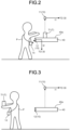
FIG. 2 to FIG. 8 are diagrams schematically illustrating an example of the operation of the management information display system 100 according to the embodiment. - As illustrated in
FIG. 2 , the tool T1 has been placed on theplacement surface 40a of theplacement stand 40. Theobject detecting unit 11 detects a shape of the tool T1, and a placement state, such as a position and a posture, of the tool T1 on theplacement surface 40a. Furthermore, theobject detecting unit 11 detects a placement state similarly for any other object T, such as the tool T2 illustrated inFIG. 1 . An example will hereinafter be described with respect to the tool T1 but similar description can be made for any other object T. Theobject detecting unit 11 transmits placement state information I1 that has been detected to thecontrol device 30. - The
control device 30 obtains, at the managementstate acquiring unit 31, theplacement state information 11. In this case, the placement state included in the placement state information I1 is a state in which the tool T1 is placed on theplacement surface 40a, for example. The determiningunit 32 thus determines that the object T has not been taken out. - As illustrated in
FIG. 2 , for a purpose of taking out the tool T1, for example, the operator P may access theplacement stand 40. When theRF tag 14 of the operator P is located at a position that is able to be read by theRFID detecting unit 12, theRFID detecting unit 12 reads theRF tag 14 and obtains identification information of the operator P, the identification having been embedded in theRF tag 14. TheRFID detecting unit 12 transmits, to thecontrol device 30, identification information I2 obtained. - After accessing the
placement stand 40, the operator P may take out the tool T1. As illustrated inFIG. 3 , when the tool T1 has been taken out by the operator P, theplacement surface 40a of the placement stand 40 is brought into a state in which the tool T1 is not placed thereon. Theobject detecting unit 11 detects theplacement surface 40a in the state in which the tool T1 is not placed thereon. Theobject detecting unit 11 transmits, to thecontrol device 30, placement state information I1 detected. Thecontrol device 30 obtains, at the managementstate acquiring unit 31, theplacement state information 11. In this case, the placement state included in the placement state information I1 is a state in which the tool T1 is not placed on theplacement surface 40a, for example. The determiningunit 32 thus determines that the tool T1 has been taken out. - When the determining
unit 32 determines that the tool T1 has been taken out, theperson identifying unit 33 identifies, based on the detection result from theRFID detecting unit 12 or theperson detecting unit 13, the object person who has taken out the tool T1. Based on identification of the operator P included in the identification information I2 or image information on the operator P included in theperson information 13, for example, theperson identifying unit 33 is able to identify the operator P as the object person. After identifying the operator P as the object person, theperson identifying unit 33 stores, into theobject information storage 37 of thestorage 35, information on the operator P who is the object person and information on the tool T1 taken out in association with each other. - Based on the determination result from the determining
unit 32 and the identification result from theperson identifying unit 33, thedisplay controller 34 sets projection information. Thedisplay controller 34 sets the projection information such that the projection information includes, for example, information on the tool T1 taken out, and information indicating the operator P that is the object person who has taken out the tool T1. Thedisplay controller 34 controls the projectingdevice 20 such that a projection image representing the set projection information is projected onto theplacement surface 40a. Thedisplay controller 34 transmits a signal including the projection information and specification information specifying a projection range on theplacement surface 40a to the projectingdevice 20. In this case, the specification information may correspond to, for example, a range including a position on theplacement surface 40a, the position being where the tool T1 had been placed. When the operator P has taken out another object T different from the tool T1, thedisplay controller 34 sets projection information similarly for the another object T. - The projecting
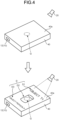
device 20 receives the signal from thecontrol device 30 and projects the projection image representing the projection information described above, over the projection range specified. As illustrated inFIG. 4 , a projection image D is thereby displayed over a range including a position Q where the tool T1 had been placed on theplacement surface 40a in a state in which the tool T1 has been taken out. The projection image D includes, for example, an image D1 indicating a name of the tool T1 taken out, an image D2 depicting an appearance of the tool T1, and an image D3 indicating identification information of the operator P that is the object person who has taken out the tool T1. Projecting the projection image D onto theplacement surface 40a corresponding to the tool T1 enables the operator P or an administrator to know that: the object T that has been taken out is the tool T1; a management location of the tool T1 is theplacement surface 40a; and the object person who has taken out the tool T1 is the operator P, in association with one another. The image D2 depicting the appearance of the tool T1 may be projected onto a position corresponding to the position Q where the tool T1 had been placed, for example. The operator P is thereby able to know the position to return the tool T1 intuitively. When the operator P has also taken out another object T different from the tool T1, thedisplay controller 34 controls the projectingdevice 20 such that a projection image is projected similarly onto aplacement surface 40a where the another object T had been placed. - After the projection image D is projected onto the
placement surface 40a, the determiningunit 32 determines, based on the detection result from theRFID detecting unit 12 or theperson detecting unit 13, whether or not the object person who has taken out the tool T1 is present around theplacement stand 40. Firstly, the determiningunit 32 determines whether or not any person is present around theplacement stand 40. For example, when anRF tag 14 has been read by theRFID detecting unit 12 or when a person has been detected by theperson detecting unit 13, the determiningunit 32 is able to determine that a person is present around theplacement stand 40. In the example illustrated inFIG. 5 , a person (the operator P) around the placement stand is detected by theperson detecting unit 13 and a result of the detection is transmitted to thecontrol device 30. Based on the detection result, the determiningunit 32 is able to determine that a person (the operator P) is present around theplacement stand 40. - When the determining
unit 32 has determined that a person is present around theplacement stand 40, theperson identifying unit 33 identifies the person around theplacement stand 40. When a determination is made by use of a detection result from theRFID detecting unit 12, theperson identifying unit 33 is able to identify the person based on the identification information embedded in theRF tag 14 of the person around theplacement stand 40. When a detection result from theperson detecting unit 13 is used, theperson identifying unit 33 is able to identify that the person is the operator P based on image information on the person included in the person information I3 and appearance information on the operator P stored in thestorage 35 in advance. - Subsequently, the determining
unit 32 determines, based on the identification result from theperson identifying unit 33, whether or not the person present around the placement stand 40 is the object person who has taken out the tool T1. Theperson identifying unit 33 has identified that the person present around the placement stand 40 is the operator P. Based on this identification result and information stored in theobject information storage 37 of thestorage 35, the determiningunit 32 is able to determine that the person present around the placement stand 40 is the operator P. - When the determining
unit 32 determines that the operator P who has taken out the tool T1 is present around theplacement stand 40, thedisplay controller 34 controls the projectingdevice 20 such that the projection image D is highlight-displayed. By this control, a projection image Da that has been highlighted is projected onto theplacement surface 40a, as illustrated inFIG. 6 . The projection image Da includes, for example, images D1a, D2a, and D3a obtaining from highlighting of the images D1, D2, and D3. The images D1a, D2a, and D3a depict, for example, the same content as the images D1, D2, and D3. The images D1a and D3a are highlight-displayed by their text being made bold. The image D2a is highlight-displayed by its outline being made bold. A specific mode of the highlight-displaying is not limited to those illustrated inFIG. 6 , and any other mode, such as a mode where an image is caused to blink, or a mode where an image is increased in brightness, may be adopted. Furthermore, when the operator P has taken out another object T different from the tool T1, thedisplay controller 34 may control the projectingdevice 20 such that a projection image is also highlight-displayed, the projection image being on aplacement surface 40a where the another object T had been placed. Highlight-displaying the projection image Da on the placement stand 40 corresponding to the tool T1 enables the operator P to readily know which placement stand 40 the tool T1 is to be returned to. - The operator P returning the tool T1 to the placement stand 40 brings the
placement surface 40a of the placement stand 40 into the state in which the tool T1 is placed on theplacement surface 40a, as illustrated inFIG. 7 . Theobject detecting unit 11 detects the placement state in which the tool T1 is placed on theplacement surface 40a. Theobject detecting unit 11 transmits, to thecontrol device 30, placement state information I1 that has been detected. Thecontrol device 30 obtains, at the managementstate acquiring unit 31, the placement state information I1. In this case, the placement state included in the placement state information I1 is changed from a state in which the tool T1 is not placed on theplacement surface 40a to a state in which the tool T1 is placed on theplacement surface 40a. The determiningunit 32 thus determines that the tool T1 has been returned. - When it is determined that the tool T1 has been returned properly, the
display controller 34 controls the projectingdevice 20 to cause the projection image Da to be erased. That is, thedisplay controller 34 controls the projectingdevice 20 such that the projection image Da projected on theplacement surface 40a is erased. This control causes the projectingdevice 20 to stop projecting the projection image Da on theplacement surface 40a. As a result, as illustrated inFIG. 8 , the projection image Da is no longer displayed on theplacement surface 40a. The managementstate acquiring unit 31 stores, into themanagement information storage 36 of thestorage 35, a position Qa where the tool T1 has newly been placed. By the above described return management without strict destination of a return position, the return position for the tool T1 becomes an optimum position as the tool T1 is repeatedly taken out and returned. -
FIG. 9 is a flowchart illustrating an example of a management information display method according to the embodiment. As illustrated inFIG. 9 , the managementstate detecting unit 10 detects various management states (Step S10). The determiningunit 32 determines, based on the detection result from the managementstate detecting unit 10, whether or not the object T has been taken out (Step S20). When it is determined at Step S20 that the object T has not been taken out (No at Step S20), the processing of Step S20 is repeated. When it is determined at Step S20 that the object T has been taken out (Yes at Step S20), theperson identifying unit 33 identifies the object person who has taken out the object T (Step S30). - When the object person who has taken out the object T is identified, the
display controller 34 sets the projection information (Step S40). At Step S40, thedisplay controller 34 sets the projection information such that the projection information includes information on the object T taken out and information indicating that the object person has taken out the object T. Thedisplay controller 34 controls the projectingdevice 20 such that the projection image D representing the set projection information is projected onto theplacement surface 40a. This control causes the projection image D to be projected onto theplacement surface 40a (Step S50). - After the projection image D is projected, the determining
unit 32 determines, based on the detection result from theperson detecting unit 13, whether or not the object person who has taken out the tool T1 is present around the placement stand 40 (Step S60). When it is determined at Step S60 that the object person who has taken out the tool T1 is not present around the placement stand 40 (No at Step S60), the processing of Step S60 is repeated. Furthermore, when it is determined that the object person who has taken out the tool T1 is present around the placement stand 40 (Yes at Step S60), the projectingdevice 20 is controlled such that the image projected onto theplacement surface 40a where the tool T1 is to be placed is highlight-displayed. This control causes the projection image Da that has been highlighted to be displayed on theplacement surface 40a (Step S70). - Thereafter, the determining
unit 32 determines whether or not the tool T1 has been returned (Step S80). When it is determined at Step S80 that the tool T1 has not been returned onto theplacement surface 40a (No at Step S80), the processing of Step S80 is repeated. Furthermore, when it is determined that the tool T1 has been returned onto theplacement surface 40a (Yes at Step S80), the projectingdevice 20 is controlled such that the position where the tool T1 has been returned to is regarded as a new regular position and the image projected on theplacement surface 40a is erased. This controls causes the projectingdevice 20 to stop the projection onto theplacement surface 40a (Step S90). - As described above, the management information display system 100 according to the embodiment includes: the management
state detecting unit 10 configured to detect the placement state of the object T placed on thepredetermined placement surface 40a such that the object T is able to be taken out; the projectingdevice 20 configured to be capable of projecting a projection image onto theplacement surface 40a; and thecontrol device 30 configured to determine, based on the detection result from the managementstate detecting unit 10, whether or not the object T has been taken out from theplacement surface 40a; to set projection information including information on the object T that has been taken out when thecontrol device 30 determines that the object T has been taken out; and to control the projectingdevice 20 such that the projection image D representing the projection information is projected onto the position where the object T had been placed on theplacement surface 40a. - Furthermore, the management information display method according to the embodiment includes: detecting the placement state of the object T placed on the
predetermined placement surface 40a such that the object T is able to be taken out; determining, based on the result of the detecting of the placement state, whether or not the object T has been taken out from theplacement surface 40a; setting the projection information including information on the object T that has been taken out when it is determined that the object T has been taken out; and projecting, by means of the projectingdevice 20, the projection image D representing the projection information onto the position where the object T had been placed on theplacement surface 40a. - According to this configuration, the projection image D representing the information on the object T that has been taken out is projected onto the
placement surface 40a when the object T has been taken out from theplacement surface 40a. Therefore, an administrator who sees theplacement surface 40a having the projection image D projected thereon is able to readily know the information related to the object T that had been placed on theplacement surface 40a. The administrator is thereby able to readily know the management state of the object T which corresponds to the placement state of the object T. - In the management information display system 100 according to the embodiment, the management
state detecting unit 10 is capable of detecting the information for identifying the object person who has taken out the object T, and thecontrol device 30 identifies, based on the detection result from the managementstate detecting unit 10, the person who has taken out the object T as the object person, when it is determined that the object T has been taken out; and sets projection information such that the projection information includes information indicating that the object person has taken out the object T. This configuration enables an administrator to know the object T that has been taken out from theplacement surface 40a and the object person who has taken out the object T in association with each other. - In the management information display system 100 according to the embodiment, the management
state detecting unit 10 is capable of detecting information for identifying the object person who has taken out the object T and information for identifying the person present around theplacement surface 40a, and thecontrol device 30 identifies, based on the detection result from the managementstate detecting unit 10, the person who has taken out the object T as the object person, when it is determined that the object T has been taken out; determines, based on the detection result from the managementstate detecting unit 10, whether or not the object person is present around theplacement surface 40a after the projection image D is projected onto theplacement surface 40a; and controls the projectingdevice 20 such that projection information is highlight-displayed when it is determined that the object person is present around theplacement surface 40a. This configuration enables the object person to readily know where to return the object T. - In the management information display system 100 according to the embodiment, after the projection image D is projected onto the
placement surface 40a, thecontrol device 30 determines, based on the detection result from the managementstate detecting unit 10, whether or not the object T has been returned to theplacement surface 40a; and when thecontrol device 30 determines that the object T has been returned, thecontrol device 30 controls the projectingdevice 20 such that the projection of the projection image D is erased. This configuration enables the object person or the administrator to readily know that the object T has been returned since the projection of the projection image D is erased when the object T has been returned. - In the management information display system 100 according to the embodiment, the
control device 30 sets the projection information such that the projection information includes image information representing the appearance of the object T when it is determined that the object T has been taken out. This configuration enables the object person or the administrator to readily know the appearance of the object T to be returned to theplacement surface 40a. - The technical scope of the present disclosure is not limited to the above described embodiment, and modifications may be made as appropriate without departing from the gist of the present disclosure. For example, in addition to the above described configuration, the management information display system 100 may have a configuration to transmit information to the operator P by output of sound. For example, the management information display system 100 may be configured to be able to determine whether or not the operator P who is the object person that has taken out the object T is looking at the
placement surface 40a of the placement stand 40 when the operator P is present around the placement stand 40 on which the object T had been placed. In this configuration, the management information display system 100 may be configured to output, by means of a sound output unit, for example, information to instruct the operator P to look at theplacement surface 40a, when it is determined that the operator P is not looking at theplacement surface 40a. - Furthermore, the case in which the object T is placed on the
placement surface 40a that is planar has been described as an example in the above described embodiment, but the embodiment is not limited to this example. A configuration in which the object T is placed in a three-dimensional placement portion or inside a container, such as a case, may be adopted. In this case, the projectingdevice 20 may project a projection image according to the shape of the placement portion for the object T. - Furthermore, the above described embodiment is configured to project a projection image D representing information on the object T that has been taken out onto a
placement surface 40a, when the object T has been taken out from theplacement surface 40a, but the projection image D is not necessarily projected constantly.FIG. 10 is a diagram schematically illustrating another example of the operation of the management information display system 100. As illustrated inFIG. 10 , in another configuration that may be adopted, when the determiningunit 32 determines, based on the detection result from the managementstate detecting unit 10, whether or not the object person is present around theplacement surface 40a and the determiningunit 32 determines that the operator P who has taken out the tool T1 is present around theplacement stand 40, thedisplay controller 34 may project the projection image D (the upper side inFIG. 10 ), and when the determiningunit 32 determines that the operator P who has taken out the tool T1 is not present around theplacement stand 40, thedisplay controller 34 may perform no projection of the projection image D (the lower side inFIG. 10 ). This configuration enables the object person to readily know where the object T is to be returned to since only the projection image D representing the information on the object T taken out by that object person is projected. - A management information display system and a management information display method according to the present disclosure may be used in, for example, a processing apparatus, such as a computer.
-
- D, Da
- PROJECTION IMAGE
- D1, D2, D3, D1a, D2a, D3a
- IMAGE
- I1
- PLACEMENT STATE INFORMATION
- I2
- IDENTIFICATION INFORMATION
- I3
- PERSON INFORMATION
- P
- OPERATOR
- Q, Qa
- POSITION
- T
- OBJECT
- T1, T2
- TOOL
- 10
- MANAGEMENT STATE DETECTING UNIT
- 11
- OBJECT DETECTING UNIT
- 12
- RFID DETECTING UNIT
- 13
- PERSON DETECTING UNIT
- 14
- RF TAG
- 20
- PROJECTING DEVICE
- 30
- CONTROL DEVICE
- 31
- MANAGEMENT STATE ACQUIRING UNIT
- 32
- DETERMINING UNIT
- 33
- PERSON IDENTIFYING UNIT
- 34
- DISPLAY CONTROLLER
- 35
- STORAGE
- 36
- MANAGEMENT INFORMATION STORAGE
- 37
- INFORMATION STORAGE
- 40
- PLACEMENT STAND
- 40a
- PLACEMENT SURFACE
- 100
- MANAGEMENT INFORMATION DISPLAY SYSTEM
Claims (6)
- A management information display system, comprising:a management state detecting unit configured to detect a placement state of an object placed on a predetermined placement area such that the object is able to be taken out;a projecting device configured to be capable of projecting a projection image onto the predetermined placement area; anda control device configured to:determine, based on a detection result from the management state detecting unit, whether or not the object has been taken out from the predetermined placement area;set projection information including information on the object that has been taken out, when the control device determines that the object has been taken out; andcontrol the projecting device such that the projection image representing the projection information is projected onto a position where the object had been placed on the predetermined placement area.
- The management information display system according to claim 1, whereinthe management state detecting unit is further configured to be capable of detecting information for identifying a person who has taken out the object, andthe control device is further configured to identify, when the control device determines that the object has been taken out, the person who has taken out the object as an object person based on the detection result from the management state detecting unit, and to set the projection information such that the projection information includes information indicating that the object person has taken out the object.
- The management information display system according to claim 1, whereinthe management state detecting unit is further configured to be capable of detecting information for identifying a person who has taken out the object and information for identifying a person around the predetermined placement area, andthe control device is further configured to:identify, when the control device determines that the object has been taken out, the person who has taken out the object as an object person based on the detection result from the management state detecting unit;determine, after the projection image is projected onto the predetermined placement area, whether or not the object person is present around the predetermined placement area based on the detection result from the management state detecting unit; andcontrol, when the control device determines that the object person is present around the predetermined placement area,
the projecting device such that the projection information is highlight-displayed. - The management information display system according to claim 1, whereinthe management state detecting unit is further configured to be capable of detecting information for identifying a person who has taken out the object and information for identifying a person around the predetermined placement area, andthe control device is further configured to:identify, when the control device determines that the object has been taken out, the person who has taken out the object as an object person based on the detection result from the management state detecting unit;determine whether or not the object person is present around the predetermined placement area based on the detection result from the management state detecting unit; andcontrol, when the control device determines that the object person is present around the predetermined placement area,
the projecting device such that the projection information is displayed, andcontrol, when the control device determines that the object person is not present around the predetermined placement area,
the projecting device such that the projection information is not displayed. - The management information display system according to any one of claim 1 to claim 4, wherein
the control device is further configured to set, when the control device determines that the object has been taken out, the projection information such that the projection information includes image information representing an appearance of the object. - A management information display method, including:detecting a placement state of an object placed on a predetermined placement area such that the object is able to be taken out;determining, based on a result of the detecting of the placement state, whether or not the object has been taken out from the predetermined placement area;setting projection information including information on the object that has been taken out when it is determined that the object has been taken out; andprojecting, by means of a projecting device, a projection image representing the projection information onto a position where the object had been placed on the predetermined placement area.
Applications Claiming Priority (2)
| Application Number | Priority Date | Filing Date | Title |
|---|---|---|---|
| JP2020092228A JP7661678B2 (en) | 2020-05-27 | 2020-05-27 | Management information display system and management information display method |
| PCT/JP2021/014679 WO2021241016A1 (en) | 2020-05-27 | 2021-04-06 | Management information display system and management information display method |
Publications (3)
| Publication Number | Publication Date |
|---|---|
| EP4141779A1 true EP4141779A1 (en) | 2023-03-01 |
| EP4141779A4 EP4141779A4 (en) | 2023-10-11 |
| EP4141779B1 EP4141779B1 (en) | 2025-09-17 |
Family
ID=78744308
Family Applications (1)
| Application Number | Title | Priority Date | Filing Date |
|---|---|---|---|
| EP21813468.2A Active EP4141779B1 (en) | 2020-05-27 | 2021-04-06 | Management information display system and management information display method |
Country Status (5)
| Country | Link |
|---|---|
| US (1) | US20230035490A1 (en) |
| EP (1) | EP4141779B1 (en) |
| JP (1) | JP7661678B2 (en) |
| CN (1) | CN115004216A (en) |
| WO (1) | WO2021241016A1 (en) |
Family Cites Families (23)
| Publication number | Priority date | Publication date | Assignee | Title |
|---|---|---|---|---|
| KR100816602B1 (en) * | 2003-02-13 | 2008-03-24 | 닛본 덴끼 가부시끼가이샤 | Unauthorized person detection device and unauthorized person detection method |
| JP5134895B2 (en) | 2007-09-14 | 2013-01-30 | 株式会社東芝 | Medical equipment management system |
| US8423431B1 (en) | 2007-12-20 | 2013-04-16 | Amazon Technologies, Inc. | Light emission guidance |
| WO2014132525A1 (en) * | 2013-03-01 | 2014-09-04 | 日本電気株式会社 | Information processing system, and information processing method |
| US9148573B2 (en) * | 2013-03-15 | 2015-09-29 | Hewlett-Packard Development Company, L.P. | Non-uniform correction illumination pattern |
| US10268983B2 (en) * | 2013-06-26 | 2019-04-23 | Amazon Technologies, Inc. | Detecting item interaction and movement |
| JPWO2015173871A1 (en) * | 2014-05-12 | 2017-04-20 | 富士通株式会社 | Product information output method, program, and control device |
| JP6197952B2 (en) | 2014-05-12 | 2017-09-20 | 富士通株式会社 | Product information output method, product information output program and control device |
| JP2016071746A (en) * | 2014-09-30 | 2016-05-09 | 富士通株式会社 | Information projection method, information projection program, and information processing device |
| JP6351500B2 (en) | 2014-12-22 | 2018-07-04 | トーヨーカネツソリューションズ株式会社 | Assortment device using projector |
| JP6411204B2 (en) | 2014-12-22 | 2018-10-24 | トーヨーカネツソリューションズ株式会社 | Projector-based picking device |
| WO2016103541A1 (en) * | 2014-12-25 | 2016-06-30 | パナソニックIpマネジメント株式会社 | Projection device |
| JP6476031B2 (en) | 2015-03-25 | 2019-02-27 | ビーコア株式会社 | Image projection apparatus, image projection method, and program |
| JP6615541B2 (en) * | 2015-09-02 | 2019-12-04 | 株式会社バンダイナムコアミューズメント | Projection system |
| CN108140358A (en) * | 2015-09-29 | 2018-06-08 | 富士胶片株式会社 | Projection device with distance image acquisition device and projection method |
| JP6517726B2 (en) | 2016-04-28 | 2019-05-22 | 住友ゴム工業株式会社 | Pickup device |
| US10762468B2 (en) | 2016-09-22 | 2020-09-01 | Amazon Technologies, Inc. | Adaptive process for guiding human-performed inventory tasks |
| JP6727159B2 (en) | 2017-03-17 | 2020-07-22 | トーヨーカネツ株式会社 | Movable projector type picking device |
| JP6330182B1 (en) * | 2017-07-25 | 2018-05-30 | 株式会社オリジナリテ | Stroller rental and bicycle parking system |
| CN111052218B (en) * | 2017-08-31 | 2022-04-19 | 三菱电机株式会社 | Optical device control apparatus, optical device control method, and storage medium |
| DE102018203175A1 (en) * | 2018-03-02 | 2019-09-05 | Kardex Produktion Deutschland Gmbh | Picking device with a virtually located in a workspace image |
| US10535146B1 (en) * | 2018-07-16 | 2020-01-14 | Accel Robotics Corporation | Projected image item tracking system |
| US10373322B1 (en) * | 2018-07-16 | 2019-08-06 | Accel Robotics Corporation | Autonomous store system that analyzes camera images to track people and their interactions with items |
-
2020
- 2020-05-27 JP JP2020092228A patent/JP7661678B2/en active Active
-
2021
- 2021-04-06 CN CN202180009938.8A patent/CN115004216A/en active Pending
- 2021-04-06 EP EP21813468.2A patent/EP4141779B1/en active Active
- 2021-04-06 WO PCT/JP2021/014679 patent/WO2021241016A1/en not_active Ceased
-
2022
- 2022-10-07 US US17/961,593 patent/US20230035490A1/en not_active Abandoned
Also Published As
| Publication number | Publication date |
|---|---|
| EP4141779A4 (en) | 2023-10-11 |
| JP7661678B2 (en) | 2025-04-15 |
| JP2021189592A (en) | 2021-12-13 |
| WO2021241016A1 (en) | 2021-12-02 |
| EP4141779B1 (en) | 2025-09-17 |
| CN115004216A (en) | 2022-09-02 |
| US20230035490A1 (en) | 2023-02-02 |
Similar Documents
| Publication | Publication Date | Title |
|---|---|---|
| US20180114183A1 (en) | Stock Level Determination | |
| JP2009214949A (en) | Article management system and information processor | |
| JP5069936B2 (en) | Material storage position management system and method | |
| US20140095119A1 (en) | System and method for location-based construction project management | |
| JP2010058908A (en) | Article management system | |
| US20090207023A1 (en) | Article management system and information processing apparatus used in the same | |
| TW201333842A (en) | Data Center Infrastructure Management System with Real-Time Enhanced Physical Board | |
| CA3000129A1 (en) | A storage and retrieval method and system | |
| KR102159966B1 (en) | Intelligent Fire Extinguisher Management System Using Smart Box | |
| US20200201513A1 (en) | Systems and methods for rfid tag locationing in augmented reality display | |
| US12333657B2 (en) | Building data platform with augmented reality based digital twins | |
| CN108629325A (en) | The determination method, apparatus and system of article position | |
| US20250086582A1 (en) | Shelf label management system, shelf label management method, and recording medium | |
| US20210216955A1 (en) | Augmented reality based package finding assistance system | |
| JP2022103189A (en) | Worksite monitoring equipment, worksite monitoring system, worksite monitoring method and program | |
| JP2016052924A (en) | Article storage management apparatus and article storage management method | |
| JP2020190950A (en) | Information processor, article identification device, and article identification system | |
| JP2020108038A (en) | Control device, control method thereof, industrial automation system, program, and storage medium | |
| EP4141779B1 (en) | Management information display system and management information display method | |
| KR102588267B1 (en) | Logistics management system | |
| CN111914587B (en) | Display item detection system and method | |
| US10943465B1 (en) | Device notification and aggregation | |
| CN119494615A (en) | A warehouse management system using infrared light curtain monitoring | |
| JP6691010B2 (en) | Detection device and detection method | |
| US11367176B2 (en) | Commodity management device and commodity management system |
Legal Events
| Date | Code | Title | Description |
|---|---|---|---|
| STAA | Information on the status of an ep patent application or granted ep patent |
Free format text: STATUS: THE INTERNATIONAL PUBLICATION HAS BEEN MADE |
|
| PUAI | Public reference made under article 153(3) epc to a published international application that has entered the european phase |
Free format text: ORIGINAL CODE: 0009012 |
|
| STAA | Information on the status of an ep patent application or granted ep patent |
Free format text: STATUS: REQUEST FOR EXAMINATION WAS MADE |
|
| 17P | Request for examination filed |
Effective date: 20221122 |
|
| AK | Designated contracting states |
Kind code of ref document: A1 Designated state(s): AL AT BE BG CH CY CZ DE DK EE ES FI FR GB GR HR HU IE IS IT LI LT LU LV MC MK MT NL NO PL PT RO RS SE SI SK SM TR |
|
| DAV | Request for validation of the european patent (deleted) | ||
| DAX | Request for extension of the european patent (deleted) | ||
| A4 | Supplementary search report drawn up and despatched |
Effective date: 20230912 |
|
| RIC1 | Information provided on ipc code assigned before grant |
Ipc: H04N 5/74 20060101ALI20230906BHEP Ipc: G09G 5/38 20060101ALI20230906BHEP Ipc: G09G 5/00 20060101ALI20230906BHEP Ipc: G06F 3/048 20130101ALI20230906BHEP Ipc: G03B 21/00 20060101ALI20230906BHEP Ipc: G06Q 50/10 20120101AFI20230906BHEP |
|
| STAA | Information on the status of an ep patent application or granted ep patent |
Free format text: STATUS: EXAMINATION IS IN PROGRESS |
|
| 17Q | First examination report despatched |
Effective date: 20240516 |
|
| GRAP | Despatch of communication of intention to grant a patent |
Free format text: ORIGINAL CODE: EPIDOSNIGR1 |
|
| STAA | Information on the status of an ep patent application or granted ep patent |
Free format text: STATUS: GRANT OF PATENT IS INTENDED |
|
| INTG | Intention to grant announced |
Effective date: 20250415 |
|
| GRAS | Grant fee paid |
Free format text: ORIGINAL CODE: EPIDOSNIGR3 |
|
| GRAA | (expected) grant |
Free format text: ORIGINAL CODE: 0009210 |
|
| STAA | Information on the status of an ep patent application or granted ep patent |
Free format text: STATUS: THE PATENT HAS BEEN GRANTED |
|
| AK | Designated contracting states |
Kind code of ref document: B1 Designated state(s): AL AT BE BG CH CY CZ DE DK EE ES FI FR GB GR HR HU IE IS IT LI LT LU LV MC MK MT NL NO PL PT RO RS SE SI SK SM TR |
|
| REG | Reference to a national code |
Ref country code: GB Ref legal event code: FG4D |
|
| REG | Reference to a national code |
Ref country code: CH Ref legal event code: EP |
|
| REG | Reference to a national code |
Ref country code: IE Ref legal event code: FG4D |
|
| REG | Reference to a national code |
Ref country code: DE Ref legal event code: R096 Ref document number: 602021038866 Country of ref document: DE |
|
| PG25 | Lapsed in a contracting state [announced via postgrant information from national office to epo] |
Ref country code: NO Free format text: LAPSE BECAUSE OF FAILURE TO SUBMIT A TRANSLATION OF THE DESCRIPTION OR TO PAY THE FEE WITHIN THE PRESCRIBED TIME-LIMIT Effective date: 20251217 |
|
| REG | Reference to a national code |
Ref country code: LT Ref legal event code: MG9D |
|
| PG25 | Lapsed in a contracting state [announced via postgrant information from national office to epo] |
Ref country code: FI Free format text: LAPSE BECAUSE OF FAILURE TO SUBMIT A TRANSLATION OF THE DESCRIPTION OR TO PAY THE FEE WITHIN THE PRESCRIBED TIME-LIMIT Effective date: 20250917 |
|
| PG25 | Lapsed in a contracting state [announced via postgrant information from national office to epo] |
Ref country code: HR Free format text: LAPSE BECAUSE OF FAILURE TO SUBMIT A TRANSLATION OF THE DESCRIPTION OR TO PAY THE FEE WITHIN THE PRESCRIBED TIME-LIMIT Effective date: 20250917 |
|
| PG25 | Lapsed in a contracting state [announced via postgrant information from national office to epo] |
Ref country code: GR Free format text: LAPSE BECAUSE OF FAILURE TO SUBMIT A TRANSLATION OF THE DESCRIPTION OR TO PAY THE FEE WITHIN THE PRESCRIBED TIME-LIMIT Effective date: 20251218 |
|
| PG25 | Lapsed in a contracting state [announced via postgrant information from national office to epo] |
Ref country code: SE Free format text: LAPSE BECAUSE OF FAILURE TO SUBMIT A TRANSLATION OF THE DESCRIPTION OR TO PAY THE FEE WITHIN THE PRESCRIBED TIME-LIMIT Effective date: 20250917 |
|
| REG | Reference to a national code |
Ref country code: NL Ref legal event code: MP Effective date: 20250917 |
|
| PG25 | Lapsed in a contracting state [announced via postgrant information from national office to epo] |
Ref country code: LV Free format text: LAPSE BECAUSE OF FAILURE TO SUBMIT A TRANSLATION OF THE DESCRIPTION OR TO PAY THE FEE WITHIN THE PRESCRIBED TIME-LIMIT Effective date: 20250917 |
|
| PG25 | Lapsed in a contracting state [announced via postgrant information from national office to epo] |
Ref country code: BG Free format text: LAPSE BECAUSE OF FAILURE TO SUBMIT A TRANSLATION OF THE DESCRIPTION OR TO PAY THE FEE WITHIN THE PRESCRIBED TIME-LIMIT Effective date: 20250917 |
|
| PG25 | Lapsed in a contracting state [announced via postgrant information from national office to epo] |
Ref country code: RS Free format text: LAPSE BECAUSE OF FAILURE TO SUBMIT A TRANSLATION OF THE DESCRIPTION OR TO PAY THE FEE WITHIN THE PRESCRIBED TIME-LIMIT Effective date: 20251217 |
|
| PG25 | Lapsed in a contracting state [announced via postgrant information from national office to epo] |
Ref country code: NL Free format text: LAPSE BECAUSE OF FAILURE TO SUBMIT A TRANSLATION OF THE DESCRIPTION OR TO PAY THE FEE WITHIN THE PRESCRIBED TIME-LIMIT Effective date: 20250917 |
|
| REG | Reference to a national code |
Ref country code: AT Ref legal event code: MK05 Ref document number: 1838988 Country of ref document: AT Kind code of ref document: T Effective date: 20250917 |
|
| PG25 | Lapsed in a contracting state [announced via postgrant information from national office to epo] |
Ref country code: SM Free format text: LAPSE BECAUSE OF FAILURE TO SUBMIT A TRANSLATION OF THE DESCRIPTION OR TO PAY THE FEE WITHIN THE PRESCRIBED TIME-LIMIT Effective date: 20250917 |
|
| PG25 | Lapsed in a contracting state [announced via postgrant information from national office to epo] |
Ref country code: ES Free format text: LAPSE BECAUSE OF FAILURE TO SUBMIT A TRANSLATION OF THE DESCRIPTION OR TO PAY THE FEE WITHIN THE PRESCRIBED TIME-LIMIT Effective date: 20250917 |
|
| PG25 | Lapsed in a contracting state [announced via postgrant information from national office to epo] |
Ref country code: AT Free format text: LAPSE BECAUSE OF FAILURE TO SUBMIT A TRANSLATION OF THE DESCRIPTION OR TO PAY THE FEE WITHIN THE PRESCRIBED TIME-LIMIT Effective date: 20250917 |
|
| PG25 | Lapsed in a contracting state [announced via postgrant information from national office to epo] |
Ref country code: IT Free format text: LAPSE BECAUSE OF FAILURE TO SUBMIT A TRANSLATION OF THE DESCRIPTION OR TO PAY THE FEE WITHIN THE PRESCRIBED TIME-LIMIT Effective date: 20250917 |
|
| PG25 | Lapsed in a contracting state [announced via postgrant information from national office to epo] |
Ref country code: IS Free format text: LAPSE BECAUSE OF FAILURE TO SUBMIT A TRANSLATION OF THE DESCRIPTION OR TO PAY THE FEE WITHIN THE PRESCRIBED TIME-LIMIT Effective date: 20260117 |
|
| PG25 | Lapsed in a contracting state [announced via postgrant information from national office to epo] |
Ref country code: PT Free format text: LAPSE BECAUSE OF FAILURE TO SUBMIT A TRANSLATION OF THE DESCRIPTION OR TO PAY THE FEE WITHIN THE PRESCRIBED TIME-LIMIT Effective date: 20260119 Ref country code: CZ Free format text: LAPSE BECAUSE OF FAILURE TO SUBMIT A TRANSLATION OF THE DESCRIPTION OR TO PAY THE FEE WITHIN THE PRESCRIBED TIME-LIMIT Effective date: 20250917 |
|
| PG25 | Lapsed in a contracting state [announced via postgrant information from national office to epo] |
Ref country code: PL Free format text: LAPSE BECAUSE OF FAILURE TO SUBMIT A TRANSLATION OF THE DESCRIPTION OR TO PAY THE FEE WITHIN THE PRESCRIBED TIME-LIMIT Effective date: 20250917 |
|
| PG25 | Lapsed in a contracting state [announced via postgrant information from national office to epo] |
Ref country code: SK Free format text: LAPSE BECAUSE OF FAILURE TO SUBMIT A TRANSLATION OF THE DESCRIPTION OR TO PAY THE FEE WITHIN THE PRESCRIBED TIME-LIMIT Effective date: 20250917 Ref country code: EE Free format text: LAPSE BECAUSE OF FAILURE TO SUBMIT A TRANSLATION OF THE DESCRIPTION OR TO PAY THE FEE WITHIN THE PRESCRIBED TIME-LIMIT Effective date: 20250917 |